EP2554469A1 - Ship encountering less frictional resistance - Google Patents
Ship encountering less frictional resistance Download PDFInfo
- Publication number
- EP2554469A1 EP2554469A1 EP11765267A EP11765267A EP2554469A1 EP 2554469 A1 EP2554469 A1 EP 2554469A1 EP 11765267 A EP11765267 A EP 11765267A EP 11765267 A EP11765267 A EP 11765267A EP 2554469 A1 EP2554469 A1 EP 2554469A1
- Authority
- EP
- European Patent Office
- Prior art keywords
- air
- air recovery
- ship
- recovery inlet
- inlet
- Prior art date
- Legal status (The legal status is an assumption and is not a legal conclusion. Google has not performed a legal analysis and makes no representation as to the accuracy of the status listed.)
- Granted
Links
Images




Classifications
-
- B—PERFORMING OPERATIONS; TRANSPORTING
- B63—SHIPS OR OTHER WATERBORNE VESSELS; RELATED EQUIPMENT
- B63B—SHIPS OR OTHER WATERBORNE VESSELS; EQUIPMENT FOR SHIPPING
- B63B1/00—Hydrodynamic or hydrostatic features of hulls or of hydrofoils
- B63B1/32—Other means for varying the inherent hydrodynamic characteristics of hulls
- B63B1/34—Other means for varying the inherent hydrodynamic characteristics of hulls by reducing surface friction
- B63B1/38—Other means for varying the inherent hydrodynamic characteristics of hulls by reducing surface friction using air bubbles or air layers gas filled volumes
-
- B—PERFORMING OPERATIONS; TRANSPORTING
- B63—SHIPS OR OTHER WATERBORNE VESSELS; RELATED EQUIPMENT
- B63B—SHIPS OR OTHER WATERBORNE VESSELS; EQUIPMENT FOR SHIPPING
- B63B1/00—Hydrodynamic or hydrostatic features of hulls or of hydrofoils
- B63B1/32—Other means for varying the inherent hydrodynamic characteristics of hulls
- B63B1/34—Other means for varying the inherent hydrodynamic characteristics of hulls by reducing surface friction
- B63B1/38—Other means for varying the inherent hydrodynamic characteristics of hulls by reducing surface friction using air bubbles or air layers gas filled volumes
- B63B2001/387—Other means for varying the inherent hydrodynamic characteristics of hulls by reducing surface friction using air bubbles or air layers gas filled volumes using means for producing a film of air or air bubbles over at least a significant portion of the hull surface
-
- Y—GENERAL TAGGING OF NEW TECHNOLOGICAL DEVELOPMENTS; GENERAL TAGGING OF CROSS-SECTIONAL TECHNOLOGIES SPANNING OVER SEVERAL SECTIONS OF THE IPC; TECHNICAL SUBJECTS COVERED BY FORMER USPC CROSS-REFERENCE ART COLLECTIONS [XRACs] AND DIGESTS
- Y02—TECHNOLOGIES OR APPLICATIONS FOR MITIGATION OR ADAPTATION AGAINST CLIMATE CHANGE
- Y02T—CLIMATE CHANGE MITIGATION TECHNOLOGIES RELATED TO TRANSPORTATION
- Y02T70/00—Maritime or waterways transport
- Y02T70/10—Measures concerning design or construction of watercraft hulls
Definitions
- the present invention relates to a frictional resistance reduced ship in which frictional resistance of a ship body is reduced by ejecting air into water.
- a technique is known in which frictional resistance of a ship body is reduced by covering a ship bottom surface with a flow of air bubbles at the time of navigation.
- problems occur such as reduction in propulsion efficiency and increase in propeller vibratory force.
- Japanese Patent Publication JP 2009-248831A discloses an air bubble introduction preventing device for preventing air bubbles from being taken in a propeller.
- the air bubble introduction preventing device has an air bubble inlet provided in a ship bottom on the side of the stern, and a gas-liquid separation chamber. Seawater which includes the air bubbles, is taken therein from an air-bubble inlet, and is separated into air and seawater in the gas-liquid separation chamber. The air as a result of the separation is emitted to the atmosphere.
- a frictional resistance reduced ship has an air ejecting unit configured to eject air into water from and air ejecting outlet provided in a ship bottom of a ship body of said ship, and an air recovery device configured to recover the air into the ship body from an air recovery inlet provided in the ship bottom.
- the air recovery inlet is arranged on the side of a stern compared with the air ejecting outlet and on the side of a bow compared with a propeller provided to the ship body.
- the propeller is arranged on a center line of the ship body.
- the air recovery inlet is provided with a central air recovery inlet provided to cross the center line, a port-side air recovery inlet provided not on the center line but on a port side so that the port-side air recovery inlet projects on the port side compared with the central air recovery inlet, and a starboard-side air recovery inlet provided not on the center line but on a starboard side so that the starboard-side air recovery inlet projects on the starboard side compared with the central air recovery inlet.
- the port-side air recovery inlet and the starboard-side air recovery inlet are positioned on the bow side compared with the central air recovery inlet.
- Each of the central air recovery inlet, the port-side air recovery inlet, and the starboard-side air recovery inlet includes a plurality of air recovery holes.
- a first width of the central air recovery inlet in a ship width direction is larger than a second width of the port-side air recovery inlet in the ship width direction and a third width of the starboard-side air recovery inlet in the ship width direction.
- Each of the central air recovery inlet, the port-side air recovery inlet, and the starboard-side air recovery inlet is formed in a belt-like shape extending in the ship width direction.
- the central air recovery inlet is formed in a belt-like shape extending in the ship width direction.
- Each of the port-side air recovery inlet and the starboard-side air recovery inlet is formed in a belt-like shape extending obliquely with respect to a ship length direction so that the respective ends of the port-side air recovery inlet and the starboard-side air recovery inlet on the side of the stern are close to the center line, and the other ends on the side of the bow are far from the center line.
- the air recovery device has a gas-liquid separation chamber configured to separate the air from the water.
- the ship bottom is formed to be a flat surface.
- the air recovery device ejects the air into the water from a first air re-ejecting outlet provided to the ship body.
- the first air re-ejecting outlet is arranged on the side of the stern compared with the air recovery inlet so as not to be arranged below the propeller when the ship body is viewed from the stern.
- the first air re-ejecting outlet is arranged on the side of the bow compared with the propeller so as to be arranged above the propeller when the ship body is viewed from the stern.
- the first air re-ejecting outlet is arranged only outside the width of the propeller when the ship body is viewed from the stern.
- the air recovery device ejects the air into the water from a second air re-ejecting outlet provided to the ship bottom.
- the second air re-ejecting outlet is arranged on the stern side compared with the air ejecting outlets and on the bow side compared with the air recovery inlets.
- the frictional resistance reduced ship which reduces frictional resistance of the ship body by ejecting the air into the water, and which prevents air bubbles from being taken in a propeller while securing and maintaining the strength of the ship body.
- the frictional resistance reduced ship has a ship body 10, an air ejecting unit 30 provided to the ship body 10, and an air recovery device 40 provided in the ship body 10.
- the ship body 10 has a bow 11, a stern 12, a ship bottom 13, a propeller 16, and a helm 17.
- the air ejecting unit 30 has air ejecting outlets 31 to 33 provided on the side of the bow 11 of the ship bottom 13, and a compressor or a blower 34.
- the air recovery device 40 has air recovery inlets 41 to 43 provided on the side of the stern 12 of the ship bottom 13, air recovery chambers 51 to 53, and a flow passage 70.
- the air recovery chambers 51 to 53 have a gas-liquid separation function.
- the air recovery chambers 51 to 53 can be referred to as gas-liquid separation chambers 51 to 53 when they have a gas-liquid separation function.
- the air recovery inlet 41 to 43 are arranged on the side of the stern 12 compared with the air ejecting outlets 31 to 33, and on the side of the bow 11 compared with the propeller 16.
- the air recovery inlet 41 is formed in a bottom plate of the air recovery chamber 51.
- the air recovery inlet 42 is formed in a bottom plate of the air recovery chamber 52.
- the air recovery inlet 43 is formed in a bottom plate of the air recovery chamber 53.
- the bottom plates of the air recovery chambers 51 to 53 are positioned on the same surface as the outer plate of the ship bottom 13.
- a ship length direction (bow-stern direction) of the ship body 10 and a ship width direction (port-starboard direction) are shown as X- and Y-directions, respectively.
- the ship body 10 has a port 14 and a starboard 15.
- the propeller 16 is arranged on a center line CL of the ship body 10.
- the air recovery inlets 41 to 43 are separated from each other.
- the air recovery inlets 41, 42, and 43 can be hereinafter referred to as a central air recovery inlet 41, a port-side air recovery inlet 42, and a starboard-side air recovery inlet, respectively.
- the air ejecting unit 30 ejects air into water from the air ejecting outlets 31 to 33 at the time of navigation.
- a flow of air bubbles covers the ship bottom 13, thereby reducing frictional resistance of the ship body 10.
- the ship bottom 13 is formed to be a flat surface, the ship bottom 13 is surely covered with the flow of air bubbles since the air bubbles are not likely to dissipate to the sides of the ship body 10 due to buoyancy.
- the air recovery device 40 recovers the air ejected into water by the air ejecting unit 30, from the air recovery inlets 41 to 43 into the ship body 10, and emits the air to the atmosphere. More in detail, seawater which includes the air bubbles, flows into the gas-liquid separation chambers 51 to 53 through the air recovery inlets 41 to 43, respectively. The gas-liquid separation chambers 51 to 53 separate air from the seawater. The air as a result of the separation is emitted to the atmosphere through the flow passage 70.
- the air recovery device 40 recovers air on the side of the bow 11 compared with the propeller 16, the air bubbles are prevented from being taken in the propeller 16.
- the central air recovery inlet 41 includes a plurality of air recovery holes 41a; the port-side air recovery inlet 42 includes a plurality of air recovery holes 42a; and the starboard-side air recovery inlet 43 includes a plurality of air recovery holes 43a.
- the central air recovery inlet 41 is formed in a belt-like shape extending in the ship width direction Y, and provided to cross the center line CL.
- the port-side air recovery inlet 42 is formed in a belt-like shape extending in the ship width direction Y, and provided not on the center line CL but on the side of the port 14 so that the port-side air recovery inlet 42 projects on the side of the port 14 compared with the central air recovery inlet 41.
- the starboard-side air recovery inlet 43 is formed in a belt-like shape extending in the ship width direction Y, and provided not on the center line CL but on the side of the starboard 15 so that the starboard-side air recovery inlet 43 projects on the side of the starboard 15 compared with the central air recovery inlet 41.
- the port-side air recovery inlet 42 and the starboard-side air recovery inlet 43 are arranged on the side of the bow 11 compared with the central air recovery inlet 41. For example, a position of the port-side air recovery inlet 42 in the ship length direction X and a position of the starboard-side air recovery inlet 43 in the ship length direction X are coincident with each other.
- the air recovery inlets 41 to 43 are formed in the above way, the strength of the ship body 10 against longitudinal bending caused by sagging and hogging is secured and maintained, compared with a case where the air recovery inlet 41 to 43 are arranged in the same position in the ship length direction X. Since the air recovery inlets 41 to 43 are provided in a wide area in the ship width direction Y, it is possible to collect or recover air in the wide area in the ship width direction Y of the ship bottom 13. The air bubbles are surely prevented from being taken in the propeller 16 since the central air recovery inlet 41 is positioned nearer to the propeller 16 than the port-side air recovery inlet 42 and the starboard-side air recovery inlet 43.
- the air bubbles are more surely prevented from being taken in the propeller 16, by increasing a width W1 of the central air recovery inlet 41 in the ship width direction Y, than a width W2 of the port-side air recovery inlet 42 in the ship width direction Y and a width W3 of the starboard-side air recovery inlet 43 in the ship width direction Y.
- the air recovery device 40 may have a flow passage 71 for supplying the recovered air to the compressor or the blower 34 in a pressure higher than atmospheric pressure.
- the compressor or the blower 34 ejects the air supplied from the air recovery device 40, from the air ejecting outlets 31 to 33 into water, energy for air ejection can be reduced compared with a case where air taken from the atmosphere is ejected.
- Fig. 2A shows an example of the central air recovery inlet 41.
- the air recovery holes 41a included in the central air recovery inlet 41 are a plurality of long holes arranged in a longitudinal direction of the central air recovery inlet 41 (e.g. the ship width direction Y).
- the longitudinal direction of each air recovery hole 41a is perpendicular to the longitudinal direction of the central air recovery inlet 41.
- the port-side air recovery inlet 42 and the starboard-side air recovery inlet 43 are formed in the same way as the central air recovery inlet 41.
- Fig. 2B shows another example of the central air recovery inlet 41.
- the air recovery holes 41a included in the central air recovery inlet 41 are a plurality of circular holes arranged along two straight lines L1 and L2 parallel to each other and extending into the longitudinal direction of the central air recovery inlet 41 (e.g. the ship width direction Y).
- the circular holes arranged along the straight line L1 and the circular holes arranged along the straight line L2 have different positions along the longitudinal direction of the central air recovery inlet 41.
- the air recovery holes 41a included in the central air recovery inlet 41 are arranged in a zigzag form.
- the strength of the ship body 10 against longitudinal bending is secured and maintained compared with a case where the air recovery holes 41a are arranged along a single straight line.
- the port-side air recovery inlet 42 and the starboard-side air recovery inlet 43 are formed in the same way as the central air recovery inlet 41.
- Fig. 2C is still another example of the central air recovery inlet 41.
- the central air recovery inlet 41 shown in Fig. 2C is the same as the central air recovery inlet 41 shown in Fig. 2B , excluding a point that the circular holes are replaced by the long holes with the same hole area.
- the longitudinal direction of each long hole is perpendicular to the longitudinal direction of the central air recovery inlet 41. In this case, the strength of the ship body 10 against longitudinal bending is secured and maintained compared with the case of Fig. 2B .
- the port-side air recovery inlet 42 and the starboard-side air recovery inlet 43 are formed in the same way as the central air recovery inlet 41.
- the frictional resistance reduced ship according to a second embodiment of the present invention is the same as the frictional resistance reduced ship according to the first embodiment, excluding the following points.
- a port-side air recovery inlet 42 and a starboard-side air recovery inlet 43 are formed in a belt-like shape extending obliquely with respect to a ship length direction X, so that the respective ends of the port-side air recovery inlet 42 and the starboard-side air recovery inlet 43 on the side of the stern 12 are nearer to a center line CL and the other ends on the side of the bow 11 are far from the center line CL.
- the ends nearer to the propeller 16, of the port-side air recovery inlet 42 and the starboard-side air recovery inlet 43 are positioned near to the center line CL, thereby preventing air bubbles from being taken in the propeller 16.
- the frictional resistance reduced ship according to the present embodiment is the same as the frictional resistance reduced ship according to the first embodiment, excluding the following point.
- the air recovery chambers 51 to 53 do not have a gas-liquid separation function, and the air recovery device 40 has a single gas-liquid separation chamber 55. Seawater which includes the air bubbles, flows into the gas-liquid separation chamber 55 through the air recovery inlet 41 to 43.
- the gas-liquid separation chamber 50 separates the air from the seawater. The air as a result of the separation is emitted to the atmosphere through the flow passage 70, or supplied to the compressor or the blower 34 through the flow passage 71.
- the frictional resistance reduced ship according to a fourth embodiment of the present invention is the same as the frictional resistance reduced ship according to the first embodiment, excluding the following point.
- the air recovery device 40 further has a compressor or a blower 80, and air re-ejecting outlets 61 to 63.
- the air re-ejecting outlets 61 to 63 are provided to a stern portion of the ship body 10.
- the air re-ejecting outlets 61 to 63 are positioned higher than the air recovery inlets 41 to 43, and positioned on the side of the stern 12 compared with the air recovery inlets 41 to 43.
- the air re-ejecting outlets 61 to 63 are positioned on the side of the bow 16 compared with the propeller 16.
- FIG. 5B With reference to Fig. 5B , the positions of the air re-ejecting outlets 61 to 63 when the ship body 10 is viewed from the stern 12 side will be described.
- the helm 17 is not shown but two tangent lines T to a circle of the propeller 16 are shown.
- the two tangent lines T are perpendicular to a ship length direction X and a ship width direction Y.
- the air re-ejecting outlets 61 to 63 are not arranged lower than a circle of the propeller 16 in a region between the two tangent lines T.
- the air re-ejecting outlets 61 to 63 are not arranged below the propeller 16, when the ship body 10 is viewed from the stern 12.
- the air re-ejecting outlet 61 is arranged higher than the propeller 16 circle in the region between the two tangent lines T. That is to say, the air re-ejecting outlet 61 is arranged above the propeller 16, when the ship body 10 is viewed from the stern 12.
- the air re-ejecting outlet 62 is arranged outside the two tangent lines T on the side of the port 14, and the air re-ejecting outlet 63 is arranged outside the two tangent lines T on the side of the starboard 15. That is to say, the air re-ejecting outlets 62 and 63 are positioned outside the width of the propeller 16, when the ship body 10 is viewed from the stern 12. In this way, the air re-ejecting outlets 61 to 63 are provided not to overlap with streamlines which pass through the propeller 16 circle.
- the compressor or the blower 80 ejects the air separated from the seawater in the gas-liquid separation chambers 51 to 53, into water from the air re-ejecting outlets 61 to 63. Consequently, an area covered with the air bubbles in the ship body 10 is increased and frictional resistance of the ship body 10 is further reduced. Since the air re-ejecting outlets 61 to 63 are not arranged below the propeller 16 when the ship body 10 is viewed from the stern 12, the air bubbles ejected from the air re-ejecting outlets 61 to 63 are prevented from being taken in the propeller 16.
- the air bubbles ejected from the air re-ejecting outlet 61 cover a portion immediately above the propeller 16 of the ship body 10, thereby reducing propagation of vibrations from the propeller 16 to the ship body 10 and improving comfort of sailors and passengers.
- the air recovered from the air recovery inlets 41 to 43 is ejected from the air re-ejecting outlets 61 to 63, thereby reducing energy for air ejection compared with a case where air taken from the atmosphere is ejected from air re-ejecting outlets 61 to 63.
- the frictional resistance reduced ship according to the modification is the same as the frictional resistance reduced ship according to the fourth embodiment, excluding the following point. Since the air re-ejecting outlets 61 to 63 are arranged higher than the air recovery inlet 41 to 43, and arranged on the side of the stern 12 compared with the air recovery inlets 41 to 43, the air recovery inlets 41 to 43 are connected to the air re-ejecting outlets 61 to 63 without the air recovery chambers 51 to 53, and the compressor or the blower 80, in the modification.
- the air recovery device 40 has a flow passage 72 which extend obliquely upward from the air recovery inlet 41 to the air re-ejecting outlet 61, a flow passage 72 which extends obliquely upward from the air recovery inlet 42 to the air re-ejecting outlet 62, and a flow passage 72 which extends obliquely upward from the air recovery inlet 43 to the air re-ejecting outlet 63.
- the seawater which includes the air bubbles and flows into the ship body 10 from the air recovery inlet 41 to 43, is discharged from the air re-ejecting outlets 61 to 63 through the flow passages 72.
- the frictional resistance reduced ship according to a fifth embodiment of the present invention is the same as the frictional resistance reduced ship according to the first embodiment, excluding the following point.
- the air recovery device 40 further has the compressor or the blower 80, air re-ejecting outlets 64 to 66 provided in the middle of the ship bottom 13, and a flow passage 73.
- the air re-ejecting outlets 64 to 66 are arranged on the side of the stern 12 compared with the air ejecting outlets 31 to 33, and arranged on the side of the bow 11 compared with the air recovery inlets 41 to 43.
- the compressor or the blower 80 is connected to the air re-ejecting outlets 64 to 66 through the flow passage 73.
- the air recovery device 40 ejects the air recovered from the air recovery inlet 41 to 43 into the ship body 10, from the air re-ejecting outlets 64 to 66 into water. More in detail, the compressor or the blower 80 ejects the air separated by the gas-liquid separation chambers 51 to 53, from the air re-ejecting outlets 64 to 66 into water. Since a density of the air bubbles is increased by covering a portion on the side of the stern 12 from the air re-ejecting outlets 64 to 66 in the ship bottom 13, the frictional resistance of the ship body 10 is further reduced.
- the air recovered from the air recovery inlets 41 to 43 is ejected from the air re-ejecting outlets 64 to 66, thereby reducing energy for air ejection compared with a case where the air taken from the atmosphere is ejected from the air re-ejecting outlets 64 to 66.
- the flow passage 73 may be short compared with a flow passage in a case of ejecting the air recovered from the air recovery inlets 41 to 43, into water from the air ejecting outlets 31 to 33. Therefore, it is possible to easily place the flow passage 73 in the ship body 10 and reduce pressure loss due to resistance of the flow passage 73.
- Each of the air re-ejecting outlets 64 to 66 includes a plurality of air ejecting holes, as in the case of the air recovery inlets 41 to 43.
- the air re-ejecting outlet 64 is formed in a belt-like shape extending in the ship width direction Y, and provided to cross the center line CL.
- the air re-ejecting outlet 65 is formed in a belt-like shape extending in the ship width direction Y, and provided not on the center line CL but on the side of port 14 so that the air re-ejecting outlet 65 projects on the side of the port 14 compared with the air re-ejecting outlet 64.
- the air re-ejecting outlet 66 is formed in a belt-like shape extending in the ship width direction Y, and provided not on the center line CL but on the side of starboard 15 so that the air re-ejecting outlet 66 projects on the side of the starboard 15 compared with the air re-ejecting outlet 64.
- the air re-ejecting outlet 65 and the air re-ejecting outlet 66 are arranged on the side of the stern 12, compared with the air re-ejecting outlet 64.
- the position of the air re-ejecting outlet 65 in the ship length direction X and the position of the air re-ejecting outlet 66 in the ship length direction X are coincident with each other.
- the air re-ejecting outlets 64 to 66 are formed in the above way, the air can be ejected from a range which is wide in the ship width direction Y of the ship bottom 13, while securing and maintaining the strength of the ship body 10 against longitudinal bending. It should be note that the air re-ejecting outlet 65 and the air re-ejecting outlet 66 may be arranged on the side of the bow 11, compared with the air re-ejecting outlet 64.
- the air ejecting holes of the air re-ejecting outlets 64 to 66 are formed in the same way as the air recovery holes 41a shown in Figs. 2A to 2C , for example.
Landscapes
- Physics & Mathematics (AREA)
- Fluid Mechanics (AREA)
- Ocean & Marine Engineering (AREA)
- Engineering & Computer Science (AREA)
- Combustion & Propulsion (AREA)
- Mechanical Engineering (AREA)
- Chemical & Material Sciences (AREA)
- Vibration Prevention Devices (AREA)
- Cleaning Or Clearing Of The Surface Of Open Water (AREA)
- Physical Water Treatments (AREA)
- Structures Of Non-Positive Displacement Pumps (AREA)
- Separation By Low-Temperature Treatments (AREA)
- Braking Arrangements (AREA)
- Exhaust Silencers (AREA)
Abstract
Description
- The present invention relates to a frictional resistance reduced ship in which frictional resistance of a ship body is reduced by ejecting air into water.
- A technique is known in which frictional resistance of a ship body is reduced by covering a ship bottom surface with a flow of air bubbles at the time of navigation. When the air bubbles are taken in propellers, problems occur such as reduction in propulsion efficiency and increase in propeller vibratory force.
- Japanese Patent Publication
JP 2009-248831A -
- [Patent Literature 1]
JP 2009-248831A - A frictional resistance reduced ship according to a first aspect of the present invention has an air ejecting unit configured to eject air into water from and air ejecting outlet provided in a ship bottom of a ship body of said ship, and an air recovery device configured to recover the air into the ship body from an air recovery inlet provided in the ship bottom. The air recovery inlet is arranged on the side of a stern compared with the air ejecting outlet and on the side of a bow compared with a propeller provided to the ship body. The propeller is arranged on a center line of the ship body. The air recovery inlet is provided with a central air recovery inlet provided to cross the center line, a port-side air recovery inlet provided not on the center line but on a port side so that the port-side air recovery inlet projects on the port side compared with the central air recovery inlet, and a starboard-side air recovery inlet provided not on the center line but on a starboard side so that the starboard-side air recovery inlet projects on the starboard side compared with the central air recovery inlet. The port-side air recovery inlet and the starboard-side air recovery inlet are positioned on the bow side compared with the central air recovery inlet. Each of the central air recovery inlet, the port-side air recovery inlet, and the starboard-side air recovery inlet includes a plurality of air recovery holes.
- A first width of the central air recovery inlet in a ship width direction is larger than a second width of the port-side air recovery inlet in the ship width direction and a third width of the starboard-side air recovery inlet in the ship width direction.
- Each of the central air recovery inlet, the port-side air recovery inlet, and the starboard-side air recovery inlet is formed in a belt-like shape extending in the ship width direction.
- The central air recovery inlet is formed in a belt-like shape extending in the ship width direction. Each of the port-side air recovery inlet and the starboard-side air recovery inlet is formed in a belt-like shape extending obliquely with respect to a ship length direction so that the respective ends of the port-side air recovery inlet and the starboard-side air recovery inlet on the side of the stern are close to the center line, and the other ends on the side of the bow are far from the center line.
- The air recovery device has a gas-liquid separation chamber configured to separate the air from the water.
- The ship bottom is formed to be a flat surface.
- The air recovery device ejects the air into the water from a first air re-ejecting outlet provided to the ship body. The first air re-ejecting outlet is arranged on the side of the stern compared with the air recovery inlet so as not to be arranged below the propeller when the ship body is viewed from the stern.
- The first air re-ejecting outlet is arranged on the side of the bow compared with the propeller so as to be arranged above the propeller when the ship body is viewed from the stern.
- The first air re-ejecting outlet is arranged only outside the width of the propeller when the ship body is viewed from the stern.
- The air recovery device ejects the air into the water from a second air re-ejecting outlet provided to the ship bottom. The second air re-ejecting outlet is arranged on the stern side compared with the air ejecting outlets and on the bow side compared with the air recovery inlets.
- According to the present invention, the frictional resistance reduced ship is provided which reduces frictional resistance of the ship body by ejecting the air into the water, and which prevents air bubbles from being taken in a propeller while securing and maintaining the strength of the ship body.
- The above objects, other objects, effect, and characteristics of the present invention will be more clarified from description of embodiments together with the attached drawings.
-
Fig. 1A is a side view of a frictional resistance reduced ship according to a first embodiment of the present invention; -
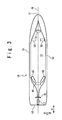
Fig. 1B is a bottom view of the frictional resistance reduced ship according to the first embodiment; -
Fig. 2A shows an example of an air recovery inlet provided to the frictional resistance reduced ship according to the first embodiment; -
Fig. 2B shows another example of the air recovery inlet provided to the frictional resistance reduced ship according to the first embodiment; -
Fig. 2C shows still another example of the air recovery inlet provided to the frictional resistance reduced ship according to the first embodiment; -
Fig. 3 is a bottom view of the frictional resistance reduced ship according to a second embodiment of the present invention; -
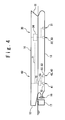
Fig. 4 is a side view of the frictional resistance reduced ship according to a third embodiment of the present invention; -
Fig. 5A is a side view of the frictional resistance reduced ship according to a fourth embodiment of the present invention; -
Fig. 5B is a back view of the frictional resistance reduced ship according to the fourth embodiment; -
Fig. 5C is a side view of the frictional resistance reduced ship according to a modification of the fourth embodiment; -
Fig. 6A is a side view of the frictional resistance reduced ship according to a fifth embodiment of the present invention; and -
Fig. 6B is a bottom view of the frictional resistance reduced ship according to the fifth embodiment. - Hereinafter, the frictional resistance reduced ship according to the present invention will be described below with reference to the attached drawings.
- With reference to
Fig. 1A , the frictional resistance reduced ship according to the first embodiment of the present invention has aship body 10, anair ejecting unit 30 provided to theship body 10, and anair recovery device 40 provided in theship body 10. Theship body 10 has abow 11, astern 12, aship bottom 13, apropeller 16, and ahelm 17. - The
air ejecting unit 30 hasair ejecting outlets 31 to 33 provided on the side of thebow 11 of theship bottom 13, and a compressor or ablower 34. - The
air recovery device 40 hasair recovery inlets 41 to 43 provided on the side of thestern 12 of theship bottom 13,air recovery chambers 51 to 53, and aflow passage 70. Theair recovery chambers 51 to 53 have a gas-liquid separation function. For example, it is possible to apply a gas-liquid separation chamber disclosed in Japanese Patent PublicationJP 2009-248831A air recovery chambers 51 to 53. Theair recovery chambers 51 to 53 can be referred to as gas-liquid separation chambers 51 to 53 when they have a gas-liquid separation function. Theair recovery inlet 41 to 43 are arranged on the side of the stern 12 compared with theair ejecting outlets 31 to 33, and on the side of thebow 11 compared with thepropeller 16. Theair recovery inlet 41 is formed in a bottom plate of theair recovery chamber 51. Theair recovery inlet 42 is formed in a bottom plate of the air recovery chamber 52. Theair recovery inlet 43 is formed in a bottom plate of the air recovery chamber 53. The bottom plates of theair recovery chambers 51 to 53 are positioned on the same surface as the outer plate of theship bottom 13. - With reference to
Fig. 1B , a ship length direction (bow-stern direction) of theship body 10 and a ship width direction (port-starboard direction) are shown as X- and Y-directions, respectively. Theship body 10 has aport 14 and astarboard 15. Thepropeller 16 is arranged on a center line CL of theship body 10. Theair recovery inlets 41 to 43 are separated from each other. Theair recovery inlets air recovery inlet 41, a port-sideair recovery inlet 42, and a starboard-side air recovery inlet, respectively. - The
air ejecting unit 30 ejects air into water from theair ejecting outlets 31 to 33 at the time of navigation. A flow of air bubbles covers the ship bottom 13, thereby reducing frictional resistance of theship body 10. When the ship bottom 13 is formed to be a flat surface, the ship bottom 13 is surely covered with the flow of air bubbles since the air bubbles are not likely to dissipate to the sides of theship body 10 due to buoyancy. - The
air recovery device 40 recovers the air ejected into water by theair ejecting unit 30, from theair recovery inlets 41 to 43 into theship body 10, and emits the air to the atmosphere. More in detail, seawater which includes the air bubbles, flows into the gas-liquid separation chambers 51 to 53 through theair recovery inlets 41 to 43, respectively. The gas-liquid separation chambers 51 to 53 separate air from the seawater. The air as a result of the separation is emitted to the atmosphere through theflow passage 70. - Since the
air recovery device 40 recovers air on the side of thebow 11 compared with thepropeller 16, the air bubbles are prevented from being taken in thepropeller 16. - The central
air recovery inlet 41 includes a plurality ofair recovery holes 41a; the port-sideair recovery inlet 42 includes a plurality ofair recovery holes 42a; and the starboard-sideair recovery inlet 43 includes a plurality ofair recovery holes 43a. The centralair recovery inlet 41 is formed in a belt-like shape extending in the ship width direction Y, and provided to cross the center line CL. The port-sideair recovery inlet 42 is formed in a belt-like shape extending in the ship width direction Y, and provided not on the center line CL but on the side of theport 14 so that the port-sideair recovery inlet 42 projects on the side of theport 14 compared with the centralair recovery inlet 41. The starboard-sideair recovery inlet 43 is formed in a belt-like shape extending in the ship width direction Y, and provided not on the center line CL but on the side of the starboard 15 so that the starboard-sideair recovery inlet 43 projects on the side of the starboard 15 compared with the centralair recovery inlet 41. The port-sideair recovery inlet 42 and the starboard-sideair recovery inlet 43 are arranged on the side of thebow 11 compared with the centralair recovery inlet 41. For example, a position of the port-sideair recovery inlet 42 in the ship length direction X and a position of the starboard-sideair recovery inlet 43 in the ship length direction X are coincident with each other. - Since the
air recovery inlets 41 to 43 are formed in the above way, the strength of theship body 10 against longitudinal bending caused by sagging and hogging is secured and maintained, compared with a case where theair recovery inlet 41 to 43 are arranged in the same position in the ship length direction X. Since theair recovery inlets 41 to 43 are provided in a wide area in the ship width direction Y, it is possible to collect or recover air in the wide area in the ship width direction Y of theship bottom 13. The air bubbles are surely prevented from being taken in thepropeller 16 since the centralair recovery inlet 41 is positioned nearer to thepropeller 16 than the port-sideair recovery inlet 42 and the starboard-sideair recovery inlet 43. The air bubbles are more surely prevented from being taken in thepropeller 16, by increasing a width W1 of the centralair recovery inlet 41 in the ship width direction Y, than a width W2 of the port-sideair recovery inlet 42 in the ship width direction Y and a width W3 of the starboard-sideair recovery inlet 43 in the ship width direction Y. - It should be noted that the
air recovery device 40 may have aflow passage 71 for supplying the recovered air to the compressor or theblower 34 in a pressure higher than atmospheric pressure. When the compressor or theblower 34 ejects the air supplied from theair recovery device 40, from theair ejecting outlets 31 to 33 into water, energy for air ejection can be reduced compared with a case where air taken from the atmosphere is ejected. -
Fig. 2A shows an example of the centralair recovery inlet 41. Theair recovery holes 41a included in the centralair recovery inlet 41 are a plurality of long holes arranged in a longitudinal direction of the central air recovery inlet 41 (e.g. the ship width direction Y). The longitudinal direction of eachair recovery hole 41a is perpendicular to the longitudinal direction of the centralair recovery inlet 41. In this case, the strength of theship body 10 against longitudinal bending is secured and maintained since spaces between the adjacentair recovery holes 41a are increased compared with a case where theair recovery holes 41a are replaced by circular holes with the same hole area. The port-sideair recovery inlet 42 and the starboard-sideair recovery inlet 43 are formed in the same way as the centralair recovery inlet 41. -
Fig. 2B shows another example of the centralair recovery inlet 41. Theair recovery holes 41a included in the centralair recovery inlet 41 are a plurality of circular holes arranged along two straight lines L1 and L2 parallel to each other and extending into the longitudinal direction of the central air recovery inlet 41 (e.g. the ship width direction Y). The circular holes arranged along the straight line L1 and the circular holes arranged along the straight line L2 have different positions along the longitudinal direction of the centralair recovery inlet 41. For example, theair recovery holes 41a included in the centralair recovery inlet 41 are arranged in a zigzag form. In this case, the strength of theship body 10 against longitudinal bending is secured and maintained compared with a case where theair recovery holes 41a are arranged along a single straight line. The port-sideair recovery inlet 42 and the starboard-sideair recovery inlet 43 are formed in the same way as the centralair recovery inlet 41. -
Fig. 2C is still another example of the centralair recovery inlet 41. The centralair recovery inlet 41 shown inFig. 2C is the same as the centralair recovery inlet 41 shown inFig. 2B , excluding a point that the circular holes are replaced by the long holes with the same hole area. The longitudinal direction of each long hole is perpendicular to the longitudinal direction of the centralair recovery inlet 41. In this case, the strength of theship body 10 against longitudinal bending is secured and maintained compared with the case ofFig. 2B . The port-sideair recovery inlet 42 and the starboard-sideair recovery inlet 43 are formed in the same way as the centralair recovery inlet 41. - With reference to
Fig. 3 , the frictional resistance reduced ship according to a second embodiment of the present invention is the same as the frictional resistance reduced ship according to the first embodiment, excluding the following points. A port-sideair recovery inlet 42 and a starboard-sideair recovery inlet 43 are formed in a belt-like shape extending obliquely with respect to a ship length direction X, so that the respective ends of the port-sideair recovery inlet 42 and the starboard-sideair recovery inlet 43 on the side of the stern 12 are nearer to a center line CL and the other ends on the side of thebow 11 are far from the center line CL. - According to the present embodiment, the ends nearer to the
propeller 16, of the port-sideair recovery inlet 42 and the starboard-sideair recovery inlet 43 are positioned near to the center line CL, thereby preventing air bubbles from being taken in thepropeller 16. - With reference to
Fig. 4 , the frictional resistance reduced ship according to a third embodiment of the present invention will be described. The frictional resistance reduced ship according to the present embodiment is the same as the frictional resistance reduced ship according to the first embodiment, excluding the following point. In the present embodiment, theair recovery chambers 51 to 53 do not have a gas-liquid separation function, and theair recovery device 40 has a single gas-liquid separation chamber 55. Seawater which includes the air bubbles, flows into the gas-liquid separation chamber 55 through theair recovery inlet 41 to 43. The gas-liquid separation chamber 50 separates the air from the seawater. The air as a result of the separation is emitted to the atmosphere through theflow passage 70, or supplied to the compressor or theblower 34 through theflow passage 71. - With reference to
Fig. 5A , the frictional resistance reduced ship according to a fourth embodiment of the present invention will be described. The frictional resistance reduced ship according to the present embodiment is the same as the frictional resistance reduced ship according to the first embodiment, excluding the following point. In the present embodiment, theair recovery device 40 further has a compressor or ablower 80, and airre-ejecting outlets 61 to 63. The airre-ejecting outlets 61 to 63 are provided to a stern portion of theship body 10. The airre-ejecting outlets 61 to 63 are positioned higher than theair recovery inlets 41 to 43, and positioned on the side of the stern 12 compared with theair recovery inlets 41 to 43. The airre-ejecting outlets 61 to 63 are positioned on the side of thebow 16 compared with thepropeller 16. - With reference to
Fig. 5B , the positions of the airre-ejecting outlets 61 to 63 when theship body 10 is viewed from the stern 12 side will be described. InFig. 5B , thehelm 17 is not shown but two tangent lines T to a circle of thepropeller 16 are shown. The two tangent lines T are perpendicular to a ship length direction X and a ship width direction Y. When theship body 10 is viewed from the stern 12, the airre-ejecting outlets 61 to 63 are not arranged lower than a circle of thepropeller 16 in a region between the two tangent lines T. That is to say, the airre-ejecting outlets 61 to 63 are not arranged below thepropeller 16, when theship body 10 is viewed from the stern 12. When theship body 10 is viewed from the stern 12, the airre-ejecting outlet 61 is arranged higher than thepropeller 16 circle in the region between the two tangent lines T. That is to say, the airre-ejecting outlet 61 is arranged above thepropeller 16, when theship body 10 is viewed from the stern 12. When theship body 10 is viewed from the stern 12, the airre-ejecting outlet 62 is arranged outside the two tangent lines T on the side of theport 14, and the airre-ejecting outlet 63 is arranged outside the two tangent lines T on the side of thestarboard 15. That is to say, the airre-ejecting outlets propeller 16, when theship body 10 is viewed from the stern 12. In this way, the airre-ejecting outlets 61 to 63 are provided not to overlap with streamlines which pass through thepropeller 16 circle. - The compressor or the
blower 80 ejects the air separated from the seawater in the gas-liquid separation chambers 51 to 53, into water from the airre-ejecting outlets 61 to 63. Consequently, an area covered with the air bubbles in theship body 10 is increased and frictional resistance of theship body 10 is further reduced. Since the airre-ejecting outlets 61 to 63 are not arranged below thepropeller 16 when theship body 10 is viewed from the stern 12, the air bubbles ejected from the airre-ejecting outlets 61 to 63 are prevented from being taken in thepropeller 16. - Furthermore, the air bubbles ejected from the air
re-ejecting outlet 61 cover a portion immediately above thepropeller 16 of theship body 10, thereby reducing propagation of vibrations from thepropeller 16 to theship body 10 and improving comfort of sailors and passengers. - If only the air
re-ejecting outlets propeller 16 when theship body 10 is viewed from the stern 12, the air bubbles are more surely prevented from being taken in thepropeller 16. - According to the present embodiment, the air recovered from the
air recovery inlets 41 to 43, is ejected from the airre-ejecting outlets 61 to 63, thereby reducing energy for air ejection compared with a case where air taken from the atmosphere is ejected from airre-ejecting outlets 61 to 63. - With reference to
Fig. 5C , the frictional resistance reduced ship according to a modification of the present embodiment will be described. The frictional resistance reduced ship according to the modification is the same as the frictional resistance reduced ship according to the fourth embodiment, excluding the following point. Since the airre-ejecting outlets 61 to 63 are arranged higher than theair recovery inlet 41 to 43, and arranged on the side of the stern 12 compared with theair recovery inlets 41 to 43, theair recovery inlets 41 to 43 are connected to the airre-ejecting outlets 61 to 63 without theair recovery chambers 51 to 53, and the compressor or theblower 80, in the modification. Theair recovery device 40 has aflow passage 72 which extend obliquely upward from theair recovery inlet 41 to the airre-ejecting outlet 61, aflow passage 72 which extends obliquely upward from theair recovery inlet 42 to the airre-ejecting outlet 62, and aflow passage 72 which extends obliquely upward from theair recovery inlet 43 to the airre-ejecting outlet 63. The seawater which includes the air bubbles and flows into theship body 10 from theair recovery inlet 41 to 43, is discharged from the airre-ejecting outlets 61 to 63 through theflow passages 72. - With reference to
Fig. 6A , the frictional resistance reduced ship according to a fifth embodiment of the present invention will be described. The frictional resistance reduced ship according to the present embodiment is the same as the frictional resistance reduced ship according to the first embodiment, excluding the following point. In the present embodiment, theair recovery device 40 further has the compressor or theblower 80, airre-ejecting outlets 64 to 66 provided in the middle of the ship bottom 13, and aflow passage 73. The airre-ejecting outlets 64 to 66 are arranged on the side of the stern 12 compared with theair ejecting outlets 31 to 33, and arranged on the side of thebow 11 compared with theair recovery inlets 41 to 43. The compressor or theblower 80 is connected to the airre-ejecting outlets 64 to 66 through theflow passage 73. - With reference to
Fig. 6B , the airre-ejecting outlets 64 to 66 are separated from each other. - The
air recovery device 40 ejects the air recovered from theair recovery inlet 41 to 43 into theship body 10, from the airre-ejecting outlets 64 to 66 into water. More in detail, the compressor or theblower 80 ejects the air separated by the gas-liquid separation chambers 51 to 53, from the airre-ejecting outlets 64 to 66 into water. Since a density of the air bubbles is increased by covering a portion on the side of the stern 12 from the airre-ejecting outlets 64 to 66 in the ship bottom 13, the frictional resistance of theship body 10 is further reduced. - According to the present embodiment, the air recovered from the
air recovery inlets 41 to 43, is ejected from the airre-ejecting outlets 64 to 66, thereby reducing energy for air ejection compared with a case where the air taken from the atmosphere is ejected from the airre-ejecting outlets 64 to 66. - Since the air
re-ejecting outlets 64 to 66 are arranged on the side of the stern 12 compared with theair ejecting outlets 31 to 33 and on the side of thebow 11 compared with theair recovery inlets 41 to 43, theflow passage 73 may be short compared with a flow passage in a case of ejecting the air recovered from theair recovery inlets 41 to 43, into water from theair ejecting outlets 31 to 33. Therefore, it is possible to easily place theflow passage 73 in theship body 10 and reduce pressure loss due to resistance of theflow passage 73. - Each of the air
re-ejecting outlets 64 to 66 includes a plurality of air ejecting holes, as in the case of theair recovery inlets 41 to 43. The airre-ejecting outlet 64 is formed in a belt-like shape extending in the ship width direction Y, and provided to cross the center line CL. The airre-ejecting outlet 65 is formed in a belt-like shape extending in the ship width direction Y, and provided not on the center line CL but on the side ofport 14 so that the airre-ejecting outlet 65 projects on the side of theport 14 compared with the airre-ejecting outlet 64. The airre-ejecting outlet 66 is formed in a belt-like shape extending in the ship width direction Y, and provided not on the center line CL but on the side ofstarboard 15 so that the airre-ejecting outlet 66 projects on the side of the starboard 15 compared with the airre-ejecting outlet 64. The airre-ejecting outlet 65 and the airre-ejecting outlet 66 are arranged on the side of the stern 12, compared with the airre-ejecting outlet 64. For example, the position of the airre-ejecting outlet 65 in the ship length direction X and the position of the airre-ejecting outlet 66 in the ship length direction X are coincident with each other. - Since the air
re-ejecting outlets 64 to 66 are formed in the above way, the air can be ejected from a range which is wide in the ship width direction Y of the ship bottom 13, while securing and maintaining the strength of theship body 10 against longitudinal bending. It should be note that the airre-ejecting outlet 65 and the airre-ejecting outlet 66 may be arranged on the side of thebow 11, compared with the airre-ejecting outlet 64. - The air ejecting holes of the air
re-ejecting outlets 64 to 66 are formed in the same way as the air recovery holes 41a shown inFigs. 2A to 2C , for example. - It is possible to eject the air from a range which is wide in the ship width direction Y of the ship bottom 13 while securing and maintaining the strength of the
ship body 10 against longitudinal bending in a portion on the side of thebow 11 of the ship bottom 13, by forming theair ejecting outlets 31 to 33 in the same way as the airre-ejecting outlets 64 to 66. - Though the frictional resistance reduced ship according to the present invention has been described above with reference to the embodiments, the frictional resistance reduced ship according to the present invention is not limited to the above embodiments. Various modifications may be made to the above embodiments. A matter disclosed in an embodiment mentioned above, and a matter disclosed in another embodiment mentioned above, can be combined.
Claims (10)
- A frictional resistance reduced ship comprising:an air ejecting unit configured to eject air into water from an air ejecting outlet provided in a ship bottom of a ship body of said ship; andan air recovery device configured to recover the air into said ship body from an air recovery inlet provided in said ship bottom,wherein said air recovery inlet is arranged on a side of a stern from said air ejecting outlet and on a side of a bow from a propeller provided to the ship body,wherein said propeller is arranged on a center line of said ship body,wherein said air recovery inlet comprises:a central air recovery inlet provided to cross the center line;a port-side air recovery inlet provided not on the center line but on a port side so that said port-side air recovery inlet projects on the port side from said central air recovery inlet; anda starboard-side air recovery inlet provided not on the center line but on a starboard side so that said starboard-side air recovery inlet projects on the starboard side from said central air recovery inlet,wherein said port-side air recovery inlet and said starboard-side air recovery inlet are arranged on the bow side from said central air recovery inlet, andwherein each of said central air recovery inlet, said port-side air recovery inlet, and said starboard-side air recovery inlet comprises a plurality of air recovery holes.
- The frictional resistance reduced ship according to claim 1, wherein a first width of said central air recovery inlet in a ship width direction is larger than a second width of said port-side air recovery inlet in the ship width direction and a third width of said starboard-side air recovery inlet in the ship width direction.
- The frictional resistance reduced ship according to claim 1 or 2, wherein each of said central air recovery inlet, said port-side air recovery inlet, and said starboard-side air recovery inlet is formed in a belt-like shape extending in a ship width direction.
- The frictional resistance reduced ship according to claim 1 or 2, wherein said central air recovery inlet is formed in a belt-like shape extending in a ship width direction, and
wherein each of said port-side air recovery inlet and said starboard-side air recovery inlet is formed in a belt-like shape extending obliquely to a ship length direction such that respective ends of said port-side air recovery inlet and said starboard-side air recovery inlet on the stern side are close to the center line, and the other ends on the bow side are far from the center line. - The frictional resistance reduced ship according to any of claims 1 to 4, wherein said air recovery device comprises a gas-liquid separation chamber configured to separate the air from the water.
- The frictional resistance reduced ship according to any of claims 1 to 5, wherein said ship bottom is formed to be a flat surface.
- The frictional resistance reduced ship according to any of claims 1 to 6, wherein said air recovery device ejects the air into the water from a first air re-ejecting outlet provided to said ship body, and
wherein said first air re-ejecting outlet is arranged on the stern side from said air recovery inlet such that said first air re-ejecting outlet is not arranged below said propeller when said ship body is viewed from said stern. - The frictional resistance reduced ship according to claim 7, wherein said first air re-ejecting outlet is arranged on the bow side from said propeller such that said first air re-ejecting outlet is arranged above said propeller when said ship body is viewed from said stern.
- The frictional resistance reduced ship according to claim 7, wherein said first air re-ejecting outlet is arranged outside a width of said propeller when said ship body is viewed from said stern.
- The frictional resistance reduced ship according to any of claims 1 to 9, wherein said air recovery device ejects the air into the water from a second air re-ejecting outlet provided to said ship bottom, and
wherein said second air re-ejecting outlet is arranged on the stern side from said air ejecting outlet and on the bow side from said air recovery inlet.
Applications Claiming Priority (2)
| Application Number | Priority Date | Filing Date | Title |
|---|---|---|---|
| JP2010085479A JP5606128B2 (en) | 2010-04-01 | 2010-04-01 | Ship bubble recovery device |
| PCT/JP2011/051906 WO2011125365A1 (en) | 2010-04-01 | 2011-01-31 | Ship encountering less frictional resistance |
Publications (3)
| Publication Number | Publication Date |
|---|---|
| EP2554469A1 true EP2554469A1 (en) | 2013-02-06 |
| EP2554469A4 EP2554469A4 (en) | 2015-07-29 |
| EP2554469B1 EP2554469B1 (en) | 2017-08-02 |
Family
ID=44708122
Family Applications (1)
| Application Number | Title | Priority Date | Filing Date |
|---|---|---|---|
| EP11765267.7A Not-in-force EP2554469B1 (en) | 2010-04-01 | 2011-01-31 | Ship encountering less frictional resistance |
Country Status (6)
| Country | Link |
|---|---|
| US (1) | US8424475B2 (en) |
| EP (1) | EP2554469B1 (en) |
| JP (1) | JP5606128B2 (en) |
| KR (3) | KR20120123582A (en) |
| CN (1) | CN102933455B (en) |
| WO (1) | WO2011125365A1 (en) |
Families Citing this family (18)
| Publication number | Priority date | Publication date | Assignee | Title |
|---|---|---|---|---|
| JP2014526421A (en) * | 2011-10-07 | 2014-10-06 | サムソン ヘビー インダストリーズ カンパニー,リミテッド | Vibration-reducing ship |
| JP5804938B2 (en) * | 2011-12-27 | 2015-11-04 | 三菱重工業株式会社 | Ship resistance reduction device |
| JP6275872B2 (en) * | 2014-05-02 | 2018-02-07 | サムソン ヘビー インダストリーズ カンパニー,リミテッド | Propeller cavitation induced vibration reduction type ship |
| JP2018535144A (en) * | 2015-12-04 | 2018-11-29 | サムスン・ヘヴィー・インダストリーズ・カンパニー・リミテッド | Friction resistance reducing device and ship including the same |
| WO2018016863A1 (en) * | 2016-07-19 | 2018-01-25 | 현대중공업 주식회사 | Friction reducing device and ship comprising same |
| CN106335619A (en) * | 2016-09-27 | 2017-01-18 | 叶泉水 | High-speed naval vessel |
| KR102018030B1 (en) | 2019-05-09 | 2019-10-14 | 이재동 | Apparatus for air lubrication of ship |
| NL2023149B1 (en) * | 2019-05-16 | 2020-12-01 | Silverstream Tech Bv | Air release unit with diverging side walls |
| USD919544S1 (en) * | 2019-05-29 | 2021-05-18 | Silverstream Technologies B.V. | Air release unit |
| KR20200137953A (en) | 2019-05-30 | 2020-12-09 | 현대중공업 주식회사 | Ship |
| KR102291080B1 (en) | 2019-05-30 | 2021-08-17 | 현대중공업 주식회사 | Ship |
| KR20200137947A (en) | 2019-05-30 | 2020-12-09 | 현대중공업 주식회사 | Ship |
| KR20200137955A (en) | 2019-05-30 | 2020-12-09 | 현대중공업 주식회사 | Ship |
| KR102297730B1 (en) | 2019-05-30 | 2021-09-06 | 현대중공업 주식회사 | Ship |
| KR102343198B1 (en) | 2020-06-16 | 2021-12-24 | 현대중공업 주식회사 | Ship |
| KR20210155591A (en) | 2020-06-16 | 2021-12-23 | 현대중공업 주식회사 | Ship |
| KR102911893B1 (en) | 2023-09-27 | 2026-01-13 | 한화오션 주식회사 | Air lubrication system of ships |
| KR102911896B1 (en) | 2023-09-27 | 2026-01-13 | 한화오션 주식회사 | Air lubrication system of ships |
Family Cites Families (12)
| Publication number | Priority date | Publication date | Assignee | Title |
|---|---|---|---|---|
| US3289623A (en) * | 1965-03-09 | 1966-12-06 | Exxon Research Engineering Co | Frictional resistance reduction using non-newtonian fluid |
| US3455267A (en) * | 1968-01-15 | 1969-07-15 | Augustine J Tucker | System for reducing frictional drag resistance on a ship hull |
| US3595191A (en) * | 1968-10-11 | 1971-07-27 | John Wakelam Grundy | Ships and boats |
| US5456201A (en) * | 1992-01-16 | 1995-10-10 | Bobst; Glen L. | Air bubble lubricated boat hull |
| JP2001097276A (en) * | 1999-09-28 | 2001-04-10 | Ishikawajima Harima Heavy Ind Co Ltd | Friction resistance reduced ship, design method thereof, and operation method of friction resistance reduced ship |
| US6789491B2 (en) * | 2000-04-03 | 2004-09-14 | Ishikawajima-Harima Heavy Industries Co., Ltd. | Friction reducing ship and method for reducing frictional resistance |
| AR055208A1 (en) * | 2006-06-30 | 2007-08-15 | Schoo Raul Alberto Iglesias | PNEUMATIC ENVIRONMENT FACILITATOR FOR THE SURFACE SLIDING OF BOATS IN THE MASS OF WATER |
| CN101049853A (en) * | 2007-05-17 | 2007-10-10 | 杨天君 | Air bubble pad decompression boat |
| CN101353079A (en) * | 2007-07-23 | 2009-01-28 | 王昌贵 | Air separated ship |
| JP5311540B2 (en) * | 2008-04-08 | 2013-10-09 | 独立行政法人海上技術安全研究所 | Air bubble entrainment prevention device for ships |
| EP2272747B1 (en) * | 2008-04-01 | 2019-05-08 | National Institute of Maritime, Port and Aviation Technology | Frictional resistance reduction device for ship |
| CN101638137A (en) * | 2008-08-03 | 2010-02-03 | 方鹏 | Device for reducing forward resistance for ship |
-
2010
- 2010-04-01 JP JP2010085479A patent/JP5606128B2/en not_active Expired - Fee Related
-
2011
- 2011-01-31 KR KR1020127025069A patent/KR20120123582A/en not_active Ceased
- 2011-01-31 US US13/017,338 patent/US8424475B2/en not_active Expired - Fee Related
- 2011-01-31 CN CN201180017237.5A patent/CN102933455B/en not_active Expired - Fee Related
- 2011-01-31 WO PCT/JP2011/051906 patent/WO2011125365A1/en not_active Ceased
- 2011-01-31 KR KR1020157018762A patent/KR20150087433A/en not_active Ceased
- 2011-01-31 KR KR1020147024615A patent/KR20140117681A/en not_active Ceased
- 2011-01-31 EP EP11765267.7A patent/EP2554469B1/en not_active Not-in-force
Non-Patent Citations (1)
| Title |
|---|
| See references of WO2011125365A1 * |
Also Published As
| Publication number | Publication date |
|---|---|
| US8424475B2 (en) | 2013-04-23 |
| KR20150087433A (en) | 2015-07-29 |
| US20110239927A1 (en) | 2011-10-06 |
| KR20120123582A (en) | 2012-11-08 |
| WO2011125365A1 (en) | 2011-10-13 |
| KR20140117681A (en) | 2014-10-07 |
| CN102933455B (en) | 2015-08-19 |
| EP2554469A4 (en) | 2015-07-29 |
| EP2554469B1 (en) | 2017-08-02 |
| CN102933455A (en) | 2013-02-13 |
| JP2011213303A (en) | 2011-10-27 |
| JP5606128B2 (en) | 2014-10-15 |
Similar Documents
| Publication | Publication Date | Title |
|---|---|---|
| US8424475B2 (en) | Air bubble recovery device of ship | |
| EP2623410B1 (en) | Air lubrication system for ship | |
| EP2623411B1 (en) | Air lubrication system for ships | |
| CN103459245B (en) | Frictional resistance reducing type ship and ship's frictional resistance reducing device | |
| EP2495163B1 (en) | Ship resistance-reduction device | |
| US8210116B2 (en) | Watercraft with hull ventilation | |
| KR20110050534A (en) | Hull friction resistance reduction device | |
| US6868798B2 (en) | Powered watercraft | |
| JP5843920B2 (en) | Ship bubble recovery device | |
| JP5653703B2 (en) | Gas recovery device and frictional resistance reduction type ship | |
| JP2011213307A (en) | Propeller induced excitation force reducing device | |
| JP5281565B2 (en) | Ship resistance reduction device | |
| JP2011213306A (en) | Friction resistance reducing type ship | |
| JP2002145171A (en) | Frictional resistance reduced type vessel | |
| CN106809339A (en) | A kind of safe pneumatic boat | |
| JP2012071785A (en) | Gas collection device and frictional resistance reducing type ship | |
| JP2013180624A (en) | Hull vibration reducing device |
Legal Events
| Date | Code | Title | Description |
|---|---|---|---|
| PUAI | Public reference made under article 153(3) epc to a published international application that has entered the european phase |
Free format text: ORIGINAL CODE: 0009012 |
|
| 17P | Request for examination filed |
Effective date: 20120928 |
|
| AK | Designated contracting states |
Kind code of ref document: A1 Designated state(s): AL AT BE BG CH CY CZ DE DK EE ES FI FR GB GR HR HU IE IS IT LI LT LU LV MC MK MT NL NO PL PT RO RS SE SI SK SM TR |
|
| DAX | Request for extension of the european patent (deleted) | ||
| RA4 | Supplementary search report drawn up and despatched (corrected) |
Effective date: 20150625 |
|
| RIC1 | Information provided on ipc code assigned before grant |
Ipc: B63H 5/07 20060101ALI20150619BHEP Ipc: B63B 1/38 20060101AFI20150619BHEP |
|
| 17Q | First examination report despatched |
Effective date: 20160629 |
|
| GRAP | Despatch of communication of intention to grant a patent |
Free format text: ORIGINAL CODE: EPIDOSNIGR1 |
|
| INTG | Intention to grant announced |
Effective date: 20170315 |
|
| GRAS | Grant fee paid |
Free format text: ORIGINAL CODE: EPIDOSNIGR3 |
|
| GRAA | (expected) grant |
Free format text: ORIGINAL CODE: 0009210 |
|
| AK | Designated contracting states |
Kind code of ref document: B1 Designated state(s): AL AT BE BG CH CY CZ DE DK EE ES FI FR GB GR HR HU IE IS IT LI LT LU LV MC MK MT NL NO PL PT RO RS SE SI SK SM TR |
|
| REG | Reference to a national code |
Ref country code: GB Ref legal event code: FG4D |
|
| REG | Reference to a national code |
Ref country code: CH Ref legal event code: EP Ref country code: AT Ref legal event code: REF Ref document number: 914126 Country of ref document: AT Kind code of ref document: T Effective date: 20170815 |
|
| REG | Reference to a national code |
Ref country code: IE Ref legal event code: FG4D |
|
| REG | Reference to a national code |
Ref country code: DE Ref legal event code: R096 Ref document number: 602011040177 Country of ref document: DE |
|
| REG | Reference to a national code |
Ref country code: NL Ref legal event code: MP Effective date: 20170802 |
|
| REG | Reference to a national code |
Ref country code: AT Ref legal event code: MK05 Ref document number: 914126 Country of ref document: AT Kind code of ref document: T Effective date: 20170802 |
|
| REG | Reference to a national code |
Ref country code: LT Ref legal event code: MG4D |
|
| PG25 | Lapsed in a contracting state [announced via postgrant information from national office to epo] |
Ref country code: HR Free format text: LAPSE BECAUSE OF FAILURE TO SUBMIT A TRANSLATION OF THE DESCRIPTION OR TO PAY THE FEE WITHIN THE PRESCRIBED TIME-LIMIT Effective date: 20170802 Ref country code: NO Free format text: LAPSE BECAUSE OF FAILURE TO SUBMIT A TRANSLATION OF THE DESCRIPTION OR TO PAY THE FEE WITHIN THE PRESCRIBED TIME-LIMIT Effective date: 20171102 Ref country code: FI Free format text: LAPSE BECAUSE OF FAILURE TO SUBMIT A TRANSLATION OF THE DESCRIPTION OR TO PAY THE FEE WITHIN THE PRESCRIBED TIME-LIMIT Effective date: 20170802 Ref country code: LT Free format text: LAPSE BECAUSE OF FAILURE TO SUBMIT A TRANSLATION OF THE DESCRIPTION OR TO PAY THE FEE WITHIN THE PRESCRIBED TIME-LIMIT Effective date: 20170802 Ref country code: SE Free format text: LAPSE BECAUSE OF FAILURE TO SUBMIT A TRANSLATION OF THE DESCRIPTION OR TO PAY THE FEE WITHIN THE PRESCRIBED TIME-LIMIT Effective date: 20170802 Ref country code: NL Free format text: LAPSE BECAUSE OF FAILURE TO SUBMIT A TRANSLATION OF THE DESCRIPTION OR TO PAY THE FEE WITHIN THE PRESCRIBED TIME-LIMIT Effective date: 20170802 Ref country code: AT Free format text: LAPSE BECAUSE OF FAILURE TO SUBMIT A TRANSLATION OF THE DESCRIPTION OR TO PAY THE FEE WITHIN THE PRESCRIBED TIME-LIMIT Effective date: 20170802 |
|
| PG25 | Lapsed in a contracting state [announced via postgrant information from national office to epo] |
Ref country code: ES Free format text: LAPSE BECAUSE OF FAILURE TO SUBMIT A TRANSLATION OF THE DESCRIPTION OR TO PAY THE FEE WITHIN THE PRESCRIBED TIME-LIMIT Effective date: 20170802 Ref country code: IS Free format text: LAPSE BECAUSE OF FAILURE TO SUBMIT A TRANSLATION OF THE DESCRIPTION OR TO PAY THE FEE WITHIN THE PRESCRIBED TIME-LIMIT Effective date: 20171202 Ref country code: PL Free format text: LAPSE BECAUSE OF FAILURE TO SUBMIT A TRANSLATION OF THE DESCRIPTION OR TO PAY THE FEE WITHIN THE PRESCRIBED TIME-LIMIT Effective date: 20170802 Ref country code: GR Free format text: LAPSE BECAUSE OF FAILURE TO SUBMIT A TRANSLATION OF THE DESCRIPTION OR TO PAY THE FEE WITHIN THE PRESCRIBED TIME-LIMIT Effective date: 20171103 Ref country code: LV Free format text: LAPSE BECAUSE OF FAILURE TO SUBMIT A TRANSLATION OF THE DESCRIPTION OR TO PAY THE FEE WITHIN THE PRESCRIBED TIME-LIMIT Effective date: 20170802 Ref country code: RS Free format text: LAPSE BECAUSE OF FAILURE TO SUBMIT A TRANSLATION OF THE DESCRIPTION OR TO PAY THE FEE WITHIN THE PRESCRIBED TIME-LIMIT Effective date: 20170802 Ref country code: BG Free format text: LAPSE BECAUSE OF FAILURE TO SUBMIT A TRANSLATION OF THE DESCRIPTION OR TO PAY THE FEE WITHIN THE PRESCRIBED TIME-LIMIT Effective date: 20171102 |
|
| PG25 | Lapsed in a contracting state [announced via postgrant information from national office to epo] |
Ref country code: CZ Free format text: LAPSE BECAUSE OF FAILURE TO SUBMIT A TRANSLATION OF THE DESCRIPTION OR TO PAY THE FEE WITHIN THE PRESCRIBED TIME-LIMIT Effective date: 20170802 Ref country code: DK Free format text: LAPSE BECAUSE OF FAILURE TO SUBMIT A TRANSLATION OF THE DESCRIPTION OR TO PAY THE FEE WITHIN THE PRESCRIBED TIME-LIMIT Effective date: 20170802 Ref country code: RO Free format text: LAPSE BECAUSE OF FAILURE TO SUBMIT A TRANSLATION OF THE DESCRIPTION OR TO PAY THE FEE WITHIN THE PRESCRIBED TIME-LIMIT Effective date: 20170802 |
|
| REG | Reference to a national code |
Ref country code: DE Ref legal event code: R097 Ref document number: 602011040177 Country of ref document: DE |
|
| PG25 | Lapsed in a contracting state [announced via postgrant information from national office to epo] |
Ref country code: SM Free format text: LAPSE BECAUSE OF FAILURE TO SUBMIT A TRANSLATION OF THE DESCRIPTION OR TO PAY THE FEE WITHIN THE PRESCRIBED TIME-LIMIT Effective date: 20170802 Ref country code: EE Free format text: LAPSE BECAUSE OF FAILURE TO SUBMIT A TRANSLATION OF THE DESCRIPTION OR TO PAY THE FEE WITHIN THE PRESCRIBED TIME-LIMIT Effective date: 20170802 Ref country code: SK Free format text: LAPSE BECAUSE OF FAILURE TO SUBMIT A TRANSLATION OF THE DESCRIPTION OR TO PAY THE FEE WITHIN THE PRESCRIBED TIME-LIMIT Effective date: 20170802 |
|
| PLBE | No opposition filed within time limit |
Free format text: ORIGINAL CODE: 0009261 |
|
| STAA | Information on the status of an ep patent application or granted ep patent |
Free format text: STATUS: NO OPPOSITION FILED WITHIN TIME LIMIT |
|
| 26N | No opposition filed |
Effective date: 20180503 |
|
| REG | Reference to a national code |
Ref country code: DE Ref legal event code: R082 Ref document number: 602011040177 Country of ref document: DE Representative=s name: HENKEL & PARTNER MBB PATENTANWALTSKANZLEI, REC, DE Ref country code: DE Ref legal event code: R082 Ref document number: 602011040177 Country of ref document: DE Representative=s name: PATENTANWAELTE HENKEL, BREUER & PARTNER MBB, DE Ref country code: DE Ref legal event code: R081 Ref document number: 602011040177 Country of ref document: DE Owner name: MITSUBISHI SHIPBUILDING CO., LTD., YOKOHAMA-SH, JP Free format text: FORMER OWNER: MITSUBISHI HEAVY INDUSTRIES, LTD., TOKYO, JP |
|
| PG25 | Lapsed in a contracting state [announced via postgrant information from national office to epo] |
Ref country code: SI Free format text: LAPSE BECAUSE OF FAILURE TO SUBMIT A TRANSLATION OF THE DESCRIPTION OR TO PAY THE FEE WITHIN THE PRESCRIBED TIME-LIMIT Effective date: 20170802 |
|
| REG | Reference to a national code |
Ref country code: CH Ref legal event code: PL |
|
| GBPC | Gb: european patent ceased through non-payment of renewal fee |
Effective date: 20180131 |
|
| PG25 | Lapsed in a contracting state [announced via postgrant information from national office to epo] |
Ref country code: FR Free format text: LAPSE BECAUSE OF NON-PAYMENT OF DUE FEES Effective date: 20180131 Ref country code: LU Free format text: LAPSE BECAUSE OF NON-PAYMENT OF DUE FEES Effective date: 20180131 |
|
| REG | Reference to a national code |
Ref country code: IE Ref legal event code: MM4A |
|
| REG | Reference to a national code |
Ref country code: FR Ref legal event code: ST Effective date: 20180928 |
|
| REG | Reference to a national code |
Ref country code: BE Ref legal event code: MM Effective date: 20180131 |
|
| PG25 | Lapsed in a contracting state [announced via postgrant information from national office to epo] |
Ref country code: LI Free format text: LAPSE BECAUSE OF NON-PAYMENT OF DUE FEES Effective date: 20180131 Ref country code: GB Free format text: LAPSE BECAUSE OF NON-PAYMENT OF DUE FEES Effective date: 20180131 Ref country code: BE Free format text: LAPSE BECAUSE OF NON-PAYMENT OF DUE FEES Effective date: 20180131 Ref country code: CH Free format text: LAPSE BECAUSE OF NON-PAYMENT OF DUE FEES Effective date: 20180131 |
|
| PG25 | Lapsed in a contracting state [announced via postgrant information from national office to epo] |
Ref country code: IE Free format text: LAPSE BECAUSE OF NON-PAYMENT OF DUE FEES Effective date: 20180131 |
|
| PG25 | Lapsed in a contracting state [announced via postgrant information from national office to epo] |
Ref country code: MC Free format text: LAPSE BECAUSE OF FAILURE TO SUBMIT A TRANSLATION OF THE DESCRIPTION OR TO PAY THE FEE WITHIN THE PRESCRIBED TIME-LIMIT Effective date: 20170802 |
|
| PG25 | Lapsed in a contracting state [announced via postgrant information from national office to epo] |
Ref country code: MT Free format text: LAPSE BECAUSE OF NON-PAYMENT OF DUE FEES Effective date: 20180131 |
|
| PG25 | Lapsed in a contracting state [announced via postgrant information from national office to epo] |
Ref country code: TR Free format text: LAPSE BECAUSE OF FAILURE TO SUBMIT A TRANSLATION OF THE DESCRIPTION OR TO PAY THE FEE WITHIN THE PRESCRIBED TIME-LIMIT Effective date: 20170802 |
|
| PG25 | Lapsed in a contracting state [announced via postgrant information from national office to epo] |
Ref country code: PT Free format text: LAPSE BECAUSE OF FAILURE TO SUBMIT A TRANSLATION OF THE DESCRIPTION OR TO PAY THE FEE WITHIN THE PRESCRIBED TIME-LIMIT Effective date: 20170802 Ref country code: HU Free format text: LAPSE BECAUSE OF FAILURE TO SUBMIT A TRANSLATION OF THE DESCRIPTION OR TO PAY THE FEE WITHIN THE PRESCRIBED TIME-LIMIT; INVALID AB INITIO Effective date: 20110131 |
|
| PG25 | Lapsed in a contracting state [announced via postgrant information from national office to epo] |
Ref country code: MK Free format text: LAPSE BECAUSE OF NON-PAYMENT OF DUE FEES Effective date: 20170802 Ref country code: CY Free format text: LAPSE BECAUSE OF FAILURE TO SUBMIT A TRANSLATION OF THE DESCRIPTION OR TO PAY THE FEE WITHIN THE PRESCRIBED TIME-LIMIT Effective date: 20170802 |
|
| PG25 | Lapsed in a contracting state [announced via postgrant information from national office to epo] |
Ref country code: AL Free format text: LAPSE BECAUSE OF FAILURE TO SUBMIT A TRANSLATION OF THE DESCRIPTION OR TO PAY THE FEE WITHIN THE PRESCRIBED TIME-LIMIT Effective date: 20170802 |
|
| PGFP | Annual fee paid to national office [announced via postgrant information from national office to epo] |
Ref country code: DE Payment date: 20211207 Year of fee payment: 12 |
|
| PGFP | Annual fee paid to national office [announced via postgrant information from national office to epo] |
Ref country code: IT Payment date: 20211213 Year of fee payment: 12 |
|
| REG | Reference to a national code |
Ref country code: DE Ref legal event code: R119 Ref document number: 602011040177 Country of ref document: DE |
|
| PG25 | Lapsed in a contracting state [announced via postgrant information from national office to epo] |
Ref country code: DE Free format text: LAPSE BECAUSE OF NON-PAYMENT OF DUE FEES Effective date: 20230801 |
|
| PG25 | Lapsed in a contracting state [announced via postgrant information from national office to epo] |
Ref country code: IT Free format text: LAPSE BECAUSE OF NON-PAYMENT OF DUE FEES Effective date: 20230131 |