EP2554404A1 - Tread band profile of a pneumatic vehicle tyre - Google Patents
Tread band profile of a pneumatic vehicle tyre Download PDFInfo
- Publication number
- EP2554404A1 EP2554404A1 EP20120176038 EP12176038A EP2554404A1 EP 2554404 A1 EP2554404 A1 EP 2554404A1 EP 20120176038 EP20120176038 EP 20120176038 EP 12176038 A EP12176038 A EP 12176038A EP 2554404 A1 EP2554404 A1 EP 2554404A1
- Authority
- EP
- European Patent Office
- Prior art keywords
- sipes
- circumferential
- circumferential groove
- pair
- tread pattern
- Prior art date
- Legal status (The legal status is an assumption and is not a legal conclusion. Google has not performed a legal analysis and makes no representation as to the accuracy of the status listed.)
- Granted
Links
- 230000015572 biosynthetic process Effects 0.000 claims description 28
- 101100334009 Caenorhabditis elegans rib-2 gene Proteins 0.000 description 19
- 238000005096 rolling process Methods 0.000 description 15
- 230000000694 effects Effects 0.000 description 4
- 230000002349 favourable effect Effects 0.000 description 4
- 238000005299 abrasion Methods 0.000 description 3
- 238000005452 bending Methods 0.000 description 3
- 230000006835 compression Effects 0.000 description 3
- 238000007906 compression Methods 0.000 description 3
- 230000002093 peripheral effect Effects 0.000 description 3
- 239000000463 material Substances 0.000 description 2
- 230000002123 temporal effect Effects 0.000 description 2
- 230000002411 adverse Effects 0.000 description 1
- 238000010276 construction Methods 0.000 description 1
- 230000006866 deterioration Effects 0.000 description 1
- 230000010354 integration Effects 0.000 description 1
- 230000008092 positive effect Effects 0.000 description 1
- 230000007261 regionalization Effects 0.000 description 1
Images


Classifications
-
- B—PERFORMING OPERATIONS; TRANSPORTING
- B60—VEHICLES IN GENERAL
- B60C—VEHICLE TYRES; TYRE INFLATION; TYRE CHANGING; CONNECTING VALVES TO INFLATABLE ELASTIC BODIES IN GENERAL; DEVICES OR ARRANGEMENTS RELATED TO TYRES
- B60C11/00—Tyre tread bands; Tread patterns; Anti-skid inserts
- B60C11/03—Tread patterns
- B60C11/12—Tread patterns characterised by the use of narrow slits or incisions, e.g. sipes
- B60C11/1259—Depth of the sipe
- B60C11/1263—Depth of the sipe different within the same sipe
-
- B—PERFORMING OPERATIONS; TRANSPORTING
- B60—VEHICLES IN GENERAL
- B60C—VEHICLE TYRES; TYRE INFLATION; TYRE CHANGING; CONNECTING VALVES TO INFLATABLE ELASTIC BODIES IN GENERAL; DEVICES OR ARRANGEMENTS RELATED TO TYRES
- B60C11/00—Tyre tread bands; Tread patterns; Anti-skid inserts
- B60C11/03—Tread patterns
- B60C11/0306—Patterns comprising block rows or discontinuous ribs
-
- B—PERFORMING OPERATIONS; TRANSPORTING
- B60—VEHICLES IN GENERAL
- B60C—VEHICLE TYRES; TYRE INFLATION; TYRE CHANGING; CONNECTING VALVES TO INFLATABLE ELASTIC BODIES IN GENERAL; DEVICES OR ARRANGEMENTS RELATED TO TYRES
- B60C11/00—Tyre tread bands; Tread patterns; Anti-skid inserts
- B60C11/03—Tread patterns
- B60C2011/0337—Tread patterns characterised by particular design features of the pattern
- B60C2011/0339—Grooves
- B60C2011/0341—Circumferential grooves
-
- B—PERFORMING OPERATIONS; TRANSPORTING
- B60—VEHICLES IN GENERAL
- B60C—VEHICLE TYRES; TYRE INFLATION; TYRE CHANGING; CONNECTING VALVES TO INFLATABLE ELASTIC BODIES IN GENERAL; DEVICES OR ARRANGEMENTS RELATED TO TYRES
- B60C11/00—Tyre tread bands; Tread patterns; Anti-skid inserts
- B60C11/03—Tread patterns
- B60C11/12—Tread patterns characterised by the use of narrow slits or incisions, e.g. sipes
- B60C11/1204—Tread patterns characterised by the use of narrow slits or incisions, e.g. sipes with special shape of the sipe
- B60C2011/1231—Tread patterns characterised by the use of narrow slits or incisions, e.g. sipes with special shape of the sipe being shallow, i.e. sipe depth of less than 3 mm
-
- B—PERFORMING OPERATIONS; TRANSPORTING
- B60—VEHICLES IN GENERAL
- B60C—VEHICLE TYRES; TYRE INFLATION; TYRE CHANGING; CONNECTING VALVES TO INFLATABLE ELASTIC BODIES IN GENERAL; DEVICES OR ARRANGEMENTS RELATED TO TYRES
- B60C11/00—Tyre tread bands; Tread patterns; Anti-skid inserts
- B60C11/03—Tread patterns
- B60C11/12—Tread patterns characterised by the use of narrow slits or incisions, e.g. sipes
- B60C11/1236—Tread patterns characterised by the use of narrow slits or incisions, e.g. sipes with special arrangements in the tread pattern
- B60C2011/1245—Tread patterns characterised by the use of narrow slits or incisions, e.g. sipes with special arrangements in the tread pattern being arranged in crossing relation, e.g. sipe mesh
-
- B—PERFORMING OPERATIONS; TRANSPORTING
- B60—VEHICLES IN GENERAL
- B60C—VEHICLE TYRES; TYRE INFLATION; TYRE CHANGING; CONNECTING VALVES TO INFLATABLE ELASTIC BODIES IN GENERAL; DEVICES OR ARRANGEMENTS RELATED TO TYRES
- B60C11/00—Tyre tread bands; Tread patterns; Anti-skid inserts
- B60C11/03—Tread patterns
- B60C11/12—Tread patterns characterised by the use of narrow slits or incisions, e.g. sipes
- B60C11/1272—Width of the sipe
- B60C2011/1277—Width of the sipe being narrow, i.e. less than 0.3 mm
Definitions
- the invention relates to a tread pattern of a pneumatic vehicle tire with over the circumference of the tire extending profile bands - such as circumferential ribs or profile block rows - which are arranged between two circumferential grooves, wherein the profile bands in the axial direction A to the profile band bounding circumferential groove is bounded in each case by an edge , which forms the profile band facing groove wall of the circumferential groove, and wherein the profiled strips in the radial direction R outwardly bounded by the bottom contact surface forming radially outer surface, with a network of sipes in the radially outer surface of at least one profile strip, which consists of Essentially in the circumferential direction U aligned fine incisions and from these sipes intersecting, extending from one circumferential groove to the other circumferential groove, transverse sipes is formed.
- profile bands - such as circumferential ribs or profile block rows - which are arranged between two circumferential grooves
- Such a construction of vehicle pneumatic tires with a network structure of intersecting sipes is known, for example, from winter tires.
- grip edges are created in the circumferential direction and in the axial direction.
- the network structure of sipes is formed with the deepest possible training of the sipes of the network to get as long as possible by the sipes obtained grip on snow and ice.
- relatively good grip properties on snow and ice can be achieved both in the circumferential direction of the vehicle tire and in the axial direction of the tire and good handling, braking and traction on snow and ice.
- the deep formation of the sipes of the network also leads to a softening of the structure, which has a negative impact on dry properties such.
- the profile bands have the desired in summer tires high circumferential rigidity and bending stiffness and thus good braking properties on dry roads, the axially extending sipes across the circumference of the vehicle pneumatic tires are arranged at a relatively large distance from each other or with low arrangement density and formed only with shallow depth. The resulting high rigidity, however, has a negative effect on the rolling resistance of the tire.
- the small incision depth of the sipes limits the effect of the gripping edges for the wet grip caused by the sipes on a relatively short life span of the tire.
- the existing sipes very deep, although the effect of the grip edges on the wet grip properties of the tire over its life is extended, however, reducing the circumferential stiffness of the profile strips and the stiffness of the profile strips against bending around parallels to the vehicle tire, causing the dry properties of Tires such as braking and traction on dry roads are adversely affected.
- the axially running sipes are made very dense in the summer tire, this can also affect the improvement of the wet grip by increased number of grip edges, but at the expense of deteriorated dry properties.
- a very dense and deep formation of such axially extending sipes can lead to an increase of the compression and thus to a further deterioration of the rolling resistance when passing through the laces.
- the invention is therefore based on the object with simple means to allow a tire with good summer properties with a good rolling resistance with good wet grip properties and good dry properties.
- the object is achieved by the formation of a tread pattern of a pneumatic vehicle tire with over the circumference of the tire extended profile bands - such as circumferential ribs or profile block rows - which are arranged between two circumferential grooves, wherein the profile bands in the axial direction A to a profile band bounding circumferential groove of each a flank is bounded, which forms the profile band facing groove wall of the circumferential groove, and wherein the profile strips in the radial direction R outwardly bounded by the bottom contact surface forming radially outer surface, with a network of sipes in the radially outer surface of at least one profile band which is formed of fine sipes oriented substantially in the circumferential direction U and of sipe-cut transverse sipes extending from one sipe groove to the other circumferential groove, according to FIGS Dissolved features of claim 1, wherein the space formed between the aligned to a circumferential groove in each case the nearest in the circumferential direction U sipe of the network and the circumferential groove
- the profile band is characterized by a limited in depth education network with fine incisions of lower sipe depth the depth t 2 formed with a high basic stiffness and only in limited individual axial sections in the edge region to the circumferential groove with an increased depth t 1 , which allows a wide opening of the sipes in these sections.
- the depth t 2 formed with a high basic stiffness and only in limited individual axial sections in the edge region to the circumferential groove with an increased depth t 1 , which allows a wide opening of the sipes in these sections.
- the network of sipes offers an extensive structure of grip edges in the circumferential and in the axial direction, which can ensure the even deeper wet sections after many kilometers driven even better wet grip.
- the network with only limited sections of increased fine incision depth allows a high stiffness of the profiled strip in the circumferential direction and against bending around the axial direction and good braking and traction properties and handling properties on dry roads, and even on new tires.
- a tread pattern of a pneumatic vehicle tire according to the features of claim 2, wherein the transverse sipes of the network in the between the to a circumferential groove respectively nearest aligned in the circumferential direction U fine sipe of the network and the circumferential groove formed axial extension portion which in the extension portion with maximum depth t 2 are formed in the entire axial extension portion between the circumferential groove closest to the circumferential groove U aligned sipe of the network and this circumferential groove are formed with the depth t 2 .
- a tread pattern of a pneumatic vehicle tire according to the features of claim 3, wherein in the one circumferential groove adjacent extending with the greater depth education t 1 axial extension portions of transverse sipes of the network in the circumferential direction U between the other circumferential groove adjacent thereto formed with the greater depth education t 1 axial extension portions of transverse sipes are arranged.
- a tread pattern of a pneumatic vehicle tire according to the features of claim 4, wherein the formed in the radially outer surface sipes of the network of the profile strip pairs of circumferentially U in a row adjacently arranged extending in the axial direction A have fine incisions with one in the radially outer Surface along the axial extent of the one circumferential groove to the other circumferential groove opposite to each other curved course.
- a tread pattern of a pneumatic vehicle tire according to the features of claim 5, wherein in the radially outer surface of the profile strip, the network with two different pairs of circumferentially U adjacent to each other arranged fine incisions with a radially outer surface along the axial extent of of the circumferential groove to the other circumferential groove opposite curved course are formed, which are distributed over the circumference of the tire arranged in an alternating sequence.
- the edges produced by the fine incisions strike different on the road surface, whereby a quiet, comfortable rolling is favored.
- a tread pattern of a pneumatic vehicle tire according to the features of claim 6, wherein the curved course of both sipes of a pair each forms a portion of an axially extending A waveform having measured in the circumferential direction U amplitude.
- the design allows the integration of an easily scalable and replicable fine sipe pattern in which, as the tire rolls off, the edges created by the sipes impact the road surface differently, thereby facilitating a smooth, comfortable unwinding.
- the design also facilitates the formation of similar sized of fine sipes and grooves enclosed rubber sections, whereby the homogeneous unwinding is further promoted.
- a tread pattern of a pneumatic vehicle tire according to the features of claim 7, wherein the curved course of both sipes of a pair each form a mutually phase-shifted portion of a waveform of the same wavelength (L 2 , L 3 ).
- This facilitates the formation of similarly sized gum sections enclosed by sipes and grooves.
- This can also be a favorable pattern for unrolling with uniform stiffness distribution in the profile and thus a particularly homogeneous unrolling enabled.
- a tread pattern of a pneumatic vehicle tire according to the features of claim 8, wherein the curved course of both sipes of a pair each form a mutually phase-shifted portion of a waveform equal in the circumferential direction U measured amplitude.
- This facilitates the formation of similarly sized gum sections enclosed by sipes and grooves.
- a pattern formation with a homogeneous structure which is particularly favorable for unwinding can be made possible with which a particularly homogeneous unwinding can be made possible.
- a tread pattern of a pneumatic vehicle tire according to the features of claim 9, wherein the phase of a sipe of a Pair is compared with the other fine incision offset by a phase angle ⁇ .
- the training allows in a simple manner, the formation of similar large enclosed by sipes and grooves rubber sections, whereby the homogeneous unwinding is further promoted.
- the training also allows short, in the temporal sequence when rolling differently als tode edges and thus a favorable noise behavior while maintaining a sufficient uniformity.
- phase of the one fine incision of the first pair relative to the one sipe of the second pair by a phase angle ( ⁇ / 2) and the phase of the second sipe of the first pair the second fine incision of the second pair by a phase angle ( ⁇ / 2) is formed offset.
- the training allows in a simple manner, the formation of similar large enclosed by sipes and grooves rubber sections, whereby the homogeneous unwinding is further promoted.
- the training also allows particularly simple short, in the temporal sequence when rolling differently als bede edges and thus a favorable noise behavior while maintaining a sufficient uniformity.
- a tread pattern of a pneumatic vehicle tire according to the features of claim 11, wherein the two sipes of the second pair intersect in the radially outer surface of the profile band - in particular in its inflection point.
- the formation hinders the formation of thin moving rubber sections between the sipes and their negative influence on the abrasion properties.
- a tread pattern of a pneumatic vehicle tire according to the features of claim 13, wherein the two sipes of a pair in extension of its wave-shaped course in the axial direction A of the tire over a profile band bounding circumferential groove away a corresponding pair of sipes in the radially outer surface another formed by the circumferential groove profile band forms.
- a tread pattern of a pneumatic vehicle tire according to the features of claim 14, wherein in the radially outer surface of the profile strip mesh with a pair of wave-shaped in the circumferential direction U aligned sipes of the same wavelength (L 1 ) and along the extension in the circumferential direction U is offset phase which extends in particular over the entire circumference of the tire, and wherein the axial distance of the two aligned in the circumferential direction U zero crossing lines of the two waveforms is smaller than their amplitude, so that the sipes intersect over the circumference of the tire.
- This allows a uniform mesh structure of sipes with even distribution of sipes and grip edges across the entire profile band.
- the Fig. 1 shows a tread pattern of a pneumatic vehicle tire for passenger cars (PKW), in the axial direction A of the pneumatic vehicle tire over the circumference of the vehicle pneumatic tire extended shoulder profile block row 1, a circumferential rib 2, a circumferential rib 3 and over the circumference of the vehicle pneumatic tire extended shoulder profile block row 4 are arranged side by side.
- the shoulder profile block rows 1 and 4 and the circumferential ribs 2 and 3 extend over the entire circumference of the pneumatic vehicle tire and are aligned in the circumferential direction U.
- the shoulder profile block row 1 and the circumferential rib 2 are spaced in a known manner in the axial direction A by a over the entire circumference of the vehicle pneumatic tire extending and aligned in the circumferential direction U circumferential groove 5 from each other.
- the circumferential rib 2 and the circumferential rib 3 are spaced apart in the axial direction A by a circumferential groove 6 which extends over the entire circumference of the pneumatic vehicle tire and is aligned in the circumferential direction U.
- the circumferential rib 3 and the shoulder profile block row 4 are spaced in a known manner in the axial direction A by an over the entire circumference of the vehicle pneumatic tire extending and aligned in the circumferential direction U circumferential groove 7 from each other.
- the ground contact surface of the pneumatic vehicle tire is formed with a ground contact width T A , which in axial direction A from the axial extension region of the shoulder profile block row 1 extends into the axial extension region of the shoulder profile block row 4.
- the ground contact width T A is dimensioned on the assembled pneumatic vehicle tire in the operating state at standard pressure.
- the circumferential grooves 5, 6 and 7 are bounded inward in the radial direction R of the pneumatic vehicle tire in each case by a groove base 23, which extends over the entire circumference of the vehicle pneumatic tire.
- the circumferential ribs 2 and 3 are bounded in the radial direction R to the outside by a surface 8 forming the ground contact surface, which in each case over the entire circumference of the vehicle pneumatic tire in the circumferential direction U and the circumferential rib 3 in the axial direction A from the circumferential groove 6 to the circumferential groove 7 extends toward and at the circumferential rib 2 in the axial direction A from the circumferential groove 5 to the circumferential groove 6.
- the circumferential groove 5 is bounded in the axial direction A to the circumferential rib 2 out by a groove wall, which forms the peripheral groove 5 toward flank of the circumferential rib 2, and the shoulder profile block row 1 through a groove wall, which is directed towards the circumferential groove 5 edge of the shoulder profile block row. 1 forms.
- the circumferential groove 6 is bounded in the axial direction A to the circumferential rib 2 out by a groove wall, which forms the peripheral groove 6 toward flank of the circumferential rib 2, and the circumferential rib 3 out through a groove wall, which is directed towards the circumferential groove 6 flank 9 of the circumferential rib 3 forms.
- the circumferential groove 7 is limited to the circumferential rib 3 through a groove wall, which forms the circumferential groove 7 toward flank 10 of the circumferential rib 3, and the shoulder profile block row 4 out through a groove wall, which forms the circumferential groove 7 executed flank of the shoulder profile block row 4.
- the flank 9 of the circumferential rib 3 extends in the radial direction R from the groove bottom 23 of the circumferential groove 6 to the radially outer surface 8 of the circumferential rib 3.
- the flank 10 of the circumferential rib 3 extends from the groove bottom 23 of the circumferential groove 7 in the radial direction R to to the radially outer surface 8 of the circumferential rib 3.
- the two edges bounding the circumferential rib 2 each extend from the groove bottom 23 of the respectively associated one Circumferential groove 5 and 6 in the radial direction R up to the circumferential rib 2 radially outwardly bounding surface.
- the circumferential rib 3 and the circumferential rib 2 are each formed in the axial direction A with a width B, which is dimensioned in the radially outer surface 8.
- the circumferential rib 3 is - as in the FIGS. 1 and 2 - a pair 11 of circumferentially aligned U and extending over the circumference of the tire extending wave-shaped sipes 12 and 13 is formed.
- the wave-shaped sipes 12 and 13 are formed wave-shaped about a common in the circumferential direction U aligned zero crossing line 10.
- the waveform of the fine incision 10 and the waveform of the fine incision 11 are each formed with the same wavelength L 1 but offset by a phase angle ⁇ in the circumferential direction U to each other.
- the waveform of the two sipes 12 and 13 is formed with the same measured from the zero crossing line 10 amplitude height H 1 .
- the two wavy lines of the sipes 12 and 13 are formed at the zero crossing line 10 mirrored each other.
- the two shaft lines of the sipes 12 and 13 intersect in each case at a distance (L1 / 2) spaced in the circumferential direction U intersections S1.
- the pitch sequence distribution is correspondingly formed alternately over the wavelength L 1 over the circumference of the pneumatic vehicle tire.
- the wavelength of both sipes 12 and 13 is the same size.
- the sipes 12 and 13 are formed along their extent in the circumferential direction U with a measured from the radially outer surface 8 of the circumferential rib 3 in the radial direction R inwardly measured depth t 2 .
- an intersection S 1 of the sipes 12 and 13 is respectively formed in the circumferential rib 3 in a circumferential position of the tire, in which also an intersection S 1 is formed in the circumferential rib 2.
- FIGS. 1 and 2 are distributed over the circumference of the vehicle pneumatic tire in the circumferential direction U in the circumferential ribs 2 and 3 respectively in alternating sequence a pair 14 of aligned in the axial direction A undulating fine incisions 15 and 16 and a pair 17 of aligned in the axial direction A wavy sipes 18 and 19 trained.
- the pair 14 of corrugated sipes 15 and 16 is formed such that the sipes 15 and 16 each extend about a zero-crossing line 21 aligned in the axial direction A, the waveform of the sipes 15 and 16 having a wavelength L 2 with (L 2 ) / 2> B.
- the waveform of the sipes 15 and 16 is in the axial direction A of the vehicle pneumatic tire offset by a phase angle ⁇ formed to each other, so that the two sipes 15 and 16 in each case on the zero crossing line 21 at a distance (L 2 / 2) intersecting points S 2 cut.
- the waveform of the sipes 15 and 16 is in each case formed with the same measured from the zero crossing line 21 in the circumferential direction U amplitude H 2 .
- the sipe 15 has in its waveform in each case a maximum in the same axial position, in which the sipe 16 has a minimum.
- the sipe 15 has in its waveform in each case in the same axial position to a minimum, in which the waveform of the sipe 16 has a maximum.
- the intersections S 2 are formed outside the circumferential ribs 2 and 3, wherein an intersection S 2 of the waveforms of the sipes 15 and 16 in the extension region of the circumferential groove 6, an intersection S 2 in the extension region of the circumferential groove 5 and an intersection S 2 in the extension region of the circumferential groove 7 is formed. These intersections S 2 are formed in the axial extension of the radially outer surface 8 in this respective circumferential groove 5, 6 and 7 into it.
- the points of intersection S 1 of the pair 11 of the wave-shaped sipes 12 and 13 aligned in the circumferential direction U are respectively in the axial position of the maxima or minima of the corrugations of the sipes 15 and 16 of the pair of sipes 14 between the two sipes 15 and 16 of a pair 14 trained.
- pairs 14 of sipes 15 and 16 each have a pair 17 of sipes 18 and 19 are formed, which are also aligned in the axial direction A of the pneumatic vehicle tire and wavy formed about a aligned in the axial direction A common zero crossing line 22 .
- the two sipes 18 and 19 of a pair 17 of sipes are each formed with the same measured in the axial direction A wavelength L 3 and each with the same measured from the zero crossing line 22 in the circumferential direction U amplitude H 3 .
- the sipes 18 and 19 are formed with their waveform such that they are formed offset in the axial direction A by a phase angle ⁇ to each other and each cut along the axial extent of the zero crossing line 22 formed on the zero crossing line 22 intersections S 3 .
- exactly one point of intersection S 3 of a pair 17 of sipes 18 and 19 in the radially outer surface 8 of the circumferential rib 2 and exactly one point of intersection S 3 of a pair 17 of sipes 18 and 19 in the radially outer surface 8 of the circumferential rib 3 is formed.
- the points of intersection S 3 of the pairs 17 of sipes 18 and 19 in the circumferential rib 3 lie in the same axial position as the points of intersection S 1 of the pair 11 of aligned in the circumferential direction U sipes 12 and 13.
- the intersections S 3 of the circumferential rib 2 in the same axial position as the points of intersection S 1 of the pair 11 of aligned in the circumferential direction U sipes 12 and 13 of the Circumferential rib 2.
- the undulations of the sipes 18 and 19 take their maxima and minima respectively in axial positions outside the circumferential rib 2 and 3.
- the sipe 18 and the sipe 19 have both in the circumferential groove 6 and in the circumferential groove 5 and in the circumferential groove 7 each an extreme value of its waveform, which formed in the same axial position as the intersections S 2 of the waveform of the sipes 15 and 16th ,
- the phase of the waveform of the sipe 15 of the pair 14 is shifted in the axial direction A from the phase of the waveform of the sipe 18 of the phase pair 17 by a phase angle ( ⁇ / 2).
- the phase of the waveform of the sipe 16 of the pair 14 is shifted in the axial direction A from the waveform of the sipe 19 of the pair 17 by a phase angle ( ⁇ / 2).
- the sipe 15 is formed in its extension region of the circumferential groove 6 on the cutting position with the sipe 13 away to the cutting position with the sipe 12 with a measured from the radially outer surface 8 depth t 2 .
- the sipe 15 is formed continuously in a first embodiment with a depth t 1 measured radially inward from the radially outer surface 8 , The in the circumferential direction U of the sipe 15 downstream sipe 16 - as in the FIGS. 1 .
- the sipe 16 is formed starting from the cutting position with the sipe 12 over its entire axial extent b 2 to the circumferential groove 6 in a first embodiment with a measured from the radially outer surface 8 radially inward depth t 1 .
- the sipe 19 is over its entire Axial extent range starting from the circumferential groove 7 to the circumferential groove 6 out with a measured radially from the radially outer surface 8 depth t 2 formed.
- FIGS. 1 is shown in the FIGS. 1 .
- the sipe 18 is in a first embodiment along its axial extent starting from the circumferential groove 7 over its entire axial extension region b 3 to the interface with the sipe 13 with a measured from the radially outer surface 8 in the radial direction R in depth t 1 and from the interface with the sipe 13 to the interface with the sipe 12 having a depth t 2 and formed from the interface with the sipe 12 over its entire axial extent b 4 to the circumferential groove 6 out again with a depth t 1 ,
- the depth t 1 is formed here with P T ⁇ t 1 > t 2 , wherein P T represents the profile depth, which, starting from the radially outer surface 8 in the radial direction R inwardly to the lowest point of the groove bottom 23 of the adjacent circumferential grooves. 6 and 7 is measured.
- the axial extent b 1 , b 2 , b 3 and b 4 is in each case with b 1 ⁇ (0.25 B), b 2 ⁇ (0.25 B), b 3 ⁇ (0.25 B) and b 4 ⁇ (0.25 B) formed.
- the depth t 2 is formed with (0.1 P T ) ⁇ t 2 ⁇ (0.4 P T ).
- the circumferential rib 3 with its sipes 12, 13, 15, 16, 18 and 19 is substantially formed with the sipe depths t 2 , but extended in the outer circumferential grooves 6, 7 axial extension regions of the aligned in the axial direction
- a fine incisions 15,16,18 and 19 each with an in the circumferential direction U in alternating order with varying depth t 1 and t 2 formed extension portions of fine incisions.
- the positions of the axial extension portions of sipes formed with the depth t 1 are on the right side formed toward the circumferential groove 7 in the circumferential direction U, respectively, to the corresponding positions of the axial extension portions of sipes formed with the depth t 1 .
- the positions of the axial extension portions of sipes formed with the depth t 2 are on the right side formed toward the circumferential groove 7 in the circumferential direction U, respectively, to the corresponding positions of the axial extension portions of sipes formed with the depth t 2 . arranged offset on the left side to the circumferential groove 6 side.
- FIGS. 4 to 7 show yet another embodiment, in each case in the sipes 15, 16 and 18 in the extension region b 1 , b 2 , b 3 and b 4, the depth t 1 in the direction of the nearest circumferential groove 6 v.7 only to an axial distance a is formed by the adjacent circumferential groove 6 and 7, respectively.
- the respective sipe 15, 16 or 18 is respectively formed only with the depth t 2 .
- the increase in the fine incision ground thereby effected in the extension region a binds the material of the circumferential rib 3 immediately adjacent to the adjacent circumferential groove 6 or 7 through the sipe.
- the respective Width a of the connection is in the extension section of the width b 1 with b 1 ⁇ 2a, in the extension section of the width b 2 with b 2 ⁇ 2a, in the extension section of the width b 3 with b 3 ⁇ 2a and in the extension section of the width b 4 with b 4 ⁇ 2a.
- a 2 mm is formed.
- the sipes 15, 16, 18 and 19 are each continued in the groove bottom 23 with an opposite the groove bottom 23 radially inwardly extending formed radial depth t 3 to reach the lowest point of the tread depth P T.
- the depth t 3 is formed with t 3 ⁇ 0.1 P T.
- t 3 0.5 mm is formed.
Abstract
Description
Die Erfindung betrifft ein Laufstreifenprofil eines Fahrzeugluftreifens mit über den Umfang des Reifens erstreckten Profilbänder - wie zum Beispiel Umfangsrippen oder Profilblockreihen -, welche zwischen zwei Umfangsrillen angeordnet sind, wobei die Profilbänder in axialer Richtung A zu einer das Profilband begrenzenden Umfangsrille jeweils von einer Flanke begrenzt ist, welche die zum Profilband weisende Rillenwand der Umfangsrille bildet, und wobei die Profilbänder in radialer Richtung R nach außen hin von einer die Bodenkontaktoberfläche bildenden radial äußeren Oberfläche begrenzt sind, mit einem Netz von Feineinschnitten in der radial äußeren Oberfläche zumindest eines Profilbandes, welches aus im Wesentlichen in Umfangsrichtung U ausgerichteten Feineinschnitten und aus diese Feineinschnitte schneidenden, von der einen Umfangsrille zur anderen Umfangsrille erstreckten, quer verlaufenden Feineinschnitten ausgebildet ist.The invention relates to a tread pattern of a pneumatic vehicle tire with over the circumference of the tire extending profile bands - such as circumferential ribs or profile block rows - which are arranged between two circumferential grooves, wherein the profile bands in the axial direction A to the profile band bounding circumferential groove is bounded in each case by an edge , which forms the profile band facing groove wall of the circumferential groove, and wherein the profiled strips in the radial direction R outwardly bounded by the bottom contact surface forming radially outer surface, with a network of sipes in the radially outer surface of at least one profile strip, which consists of Essentially in the circumferential direction U aligned fine incisions and from these sipes intersecting, extending from one circumferential groove to the other circumferential groove, transverse sipes is formed.
Eine derartige Ausbildung von Fahrzeugluftreifen mit Netzstruktur von sich kreuzenden Feineinschnitten ist zum Beispiel von Winterreifen bekannt. Hierdurch werden Griffkanten in Umfangsrichtung und in axialer Richtung geschaffen. Bei Winterreifen wird dabei die Netzstruktur von Feineinschnitten mit einer möglichst tiefen Ausbildung der Feineinschnitte des Netzes ausgebildet, um den durch die Feineinschnitte erzielten Griff auf Schnee und Eis möglichst lange zu erhalten. Hierdurch können relativ gute Griffeigenschaften auf Schnee und Eis sowohl in Umfangsrichtung des Fahrzeugreifens als auch in axialer Richtung des Reifens und gute Handling-, Brems- und Traktionseigenschaften auf Schnee und Eis erzielt werden. Die tiefe Ausbildung der Feineinschnitte des Netzes führt jedoch auch zu einer Aufweichung der Struktur, die sich negativ auf Trockeneigenschaften, wie z. B. Brems- und Traktionseigenschaften und Handlingeigenschaften auf trockener Straße, auswirken können. Diesen wird üblicherweise mit zusätzlichen Maßnahmen versucht, entgegenzuwirken. Die tiefe Ausbildung des Netzes von Feineinschnitten kann darüber hinaus beim Durchlaufen des Reifenlatsches aufgrund der Verformung des Materials unter der wirkenden Last zu einer erhöhten Kompression im Profilelement führen, welche sich negativ auf den Rollwiderstand auswirkt.Such a construction of vehicle pneumatic tires with a network structure of intersecting sipes is known, for example, from winter tires. As a result, grip edges are created in the circumferential direction and in the axial direction. In winter tires while the network structure of sipes is formed with the deepest possible training of the sipes of the network to get as long as possible by the sipes obtained grip on snow and ice. As a result, relatively good grip properties on snow and ice can be achieved both in the circumferential direction of the vehicle tire and in the axial direction of the tire and good handling, braking and traction on snow and ice. However, the deep formation of the sipes of the network also leads to a softening of the structure, which has a negative impact on dry properties such. As braking and traction properties and handling properties on dry roads, can affect. This is usually with additional measures trying to counteract. The deep formation of the network of sipes can also lead to an increased compression in the profile element when passing through the tire lash due to the deformation of the material under the load acting, which has a negative effect on the rolling resistance.
Bei Sommerreifen, welche spezielle auf die sommerlichen Temperaturen und Witterungsverhältnisse abgestimmte Eigenschaften aufweisen, ist es bekannt, in Profilbändern Feineinschnitte in axialer Richtung des Fahrzeugluftreifens zur Verbesserung der Nassgriffeigenschaften wie z.B. Bremsen auf nasser Straße auszubilden. Damit die Profilbänder die bei Sommerreifen gewünschte hohe Umfangssteifigkeit und Biegesteifigkeit und somit gute Bremseigenschaften auf trockenen Straßen aufweisen, sind über den Umfang des Fahrzeugluftreifens hinweg die axial verlaufenden Feineinschnitte mit relativ großem Abstand zueinander bzw. mit geringer Anordnungsdichte angeordnet und nur mit geringer Tiefe ausgebildet. Die hierdurch erreichte hohe Steifigkeit wirkt sich jedoch negativ auf den Rollwiderstand des Reifens aus. Die geringe Einschnitttiefe der Feineinschnitte begrenzt die Wirkung der durch die Feineinschnitte bewirkten Griffkanten für den Nassgriff auf einen relativ kurzen Lebensabschnitt des Reifens. Werden in alternativer Ausbildung die vorhandenen Feineinschnitte sehr tief ausgebildet, wird zwar die Wirkung der Griffkanten auf die Nassgriffeigenschaften des Reifens über dessen Lebensdauer verlängert, allerdings unter Reduktion der Umfangssteifigkeit der Profilbänder und der Steifigkeit der Profilbänder gegen Verbiegen um Achsparallelen des Fahrzeugreifens, wodurch die Trockeneigenschaften des Reifens wie Bremsen und Traktion auf trockener Straße negativ beeinflusst werden. Werden beim Sommerreifen die axial verlaufenden Feineinschnitte sehr dicht ausgebildet, kann sich dies ebenfalls zur Verbesserung des Nassgriffs durch erhöhte Zahl der Griffkanten, aber unter Inkaufnahme verschlechterter Trockeneigenschaften auswirken. Eine sehr dichte und tiefe Ausbildung derartiger axial verlaufender Feineinschnitte kann beim Durchlaufen des Latsches zur Erhöhung der Kompression und somit zu einer weiteren Verschlechterung des Rollwiderstandes führen.In summer tires, which have special on the summer temperatures and weather conditions tuned properties, it is known to form in profile bands fine incisions in the axial direction of the pneumatic vehicle tire to improve the wet grip properties such as braking on wet roads. Thus, the profile bands have the desired in summer tires high circumferential rigidity and bending stiffness and thus good braking properties on dry roads, the axially extending sipes across the circumference of the vehicle pneumatic tires are arranged at a relatively large distance from each other or with low arrangement density and formed only with shallow depth. The resulting high rigidity, however, has a negative effect on the rolling resistance of the tire. The small incision depth of the sipes limits the effect of the gripping edges for the wet grip caused by the sipes on a relatively short life span of the tire. Are formed in alternative training, the existing sipes very deep, although the effect of the grip edges on the wet grip properties of the tire over its life is extended, however, reducing the circumferential stiffness of the profile strips and the stiffness of the profile strips against bending around parallels to the vehicle tire, causing the dry properties of Tires such as braking and traction on dry roads are adversely affected. If the axially running sipes are made very dense in the summer tire, this can also affect the improvement of the wet grip by increased number of grip edges, but at the expense of deteriorated dry properties. A very dense and deep formation of such axially extending sipes can lead to an increase of the compression and thus to a further deterioration of the rolling resistance when passing through the laces.
Der Erfindung liegt daher die Aufgabe zugrunde, mit einfachen Mitteln einen Reifen mit guten Sommereigenschaften mit einem gutem Rollwiderstand bei guten Nassgriffeigenschaften und bei guten Trockeneigenschafften zu ermöglichen.The invention is therefore based on the object with simple means to allow a tire with good summer properties with a good rolling resistance with good wet grip properties and good dry properties.
Die Aufgabe wird erfindungsgemäß durch die Ausbildung eines Laufstreifenprofiles eines Fahrzeugluftreifens mit über den Umfang des Reifens erstreckten Profilbändern - wie zum Beispiel Umfangsrippen oder Profilblockreihen -, welche zwischen zwei Umfangsrillen angeordnet sind, wobei die Profilbänder in axialer Richtung A zu einer das Profilband begrenzenden Umfangsrille jeweils von einer Flanke begrenzt ist, welche die zum Profilband weisende Rillenwand der Umfangsrille bildet, und wobei die Profilbänder in radialer Richtung R nach außen hin von einer die Bodenkontaktoberfläche bildenden radial äußeren Oberfläche begrenzt sind, mit einem Netz von Feineinschnitten in der radial äußeren Oberfläche zumindest eines Profilbandes, welches aus im Wesentlichen in Umfangsrichtung U ausgerichteten Feineinschnitten und aus diese Feineinschnitte schneidenden, von der einen Umfangsrille zur anderen Umfangsrille erstreckten, quer verlaufenden Feineinschnitten ausgebildet ist, gemäß den Merkmalen von Anspruch 1 gelöst, bei dem die zwischen dem zu einer Umfangsrille jeweils nächstgelegenen in Umfangsrichtung U ausgerichteten Feineinschnitt des Netzes und der Umfangsrille ausgebildeten axialen Erstreckungsabschnitte der querverlaufenden Feineinschnitte mit einer unterschiedlichen in radialer Richtung R gemessenen maximalen Tiefe mit wenigstens zwei unterschiedlichen maximalen Tiefen t1 und t2 mit t1 > t2 ausgebildet sind, wobei die axialen Erstreckungsabschnitte der Feineinschnitte unterschiedlicher Tiefenausbildung in Umfangsrichtung U des Fahrzeugluftreifens in alternierender Abfolge angeordnet sind, und bei dem der in dem zwischen den beiden jeweils zu einer der beiden Umfangsrillen nächstgelegenen und in Umfangsrichtung U ausgerichteten Feineinschnitt des Netzes ausgebildete axiale Erstreckungsabschnitt der querverlaufenden Feineinschnitte mit der kleineren t2 der wenigstens zwei Tiefen der Feineinschnitte ausgebildet ist.The object is achieved by the formation of a tread pattern of a pneumatic vehicle tire with over the circumference of the tire extended profile bands - such as circumferential ribs or profile block rows - which are arranged between two circumferential grooves, wherein the profile bands in the axial direction A to a profile band bounding circumferential groove of each a flank is bounded, which forms the profile band facing groove wall of the circumferential groove, and wherein the profile strips in the radial direction R outwardly bounded by the bottom contact surface forming radially outer surface, with a network of sipes in the radially outer surface of at least one profile band which is formed of fine sipes oriented substantially in the circumferential direction U and of sipe-cut transverse sipes extending from one sipe groove to the other circumferential groove, according to FIGS Dissolved features of
Mit Hilfe des Netzes von Feineinschnitten können gute Handling- und Brems- und Traktionseigenschaften auf nasser Straße erzielt werden. Das Profilband ist durch ein in ihrer Tiefenausbildung begrenztes Netz mit Feineinschnitten geringerer Feineinschnitttiefe der Tiefe t2 mit einer hohen Grundsteifigkeit ausgebildet und lediglich in begrenzten einzelnen axialen Abschnitten im Randbereich zur Umfangsrille hin mit einer erhöhten Tiefe t1, die ein weites Öffnen der Feineinschnitte in diesen Abschnitten ermöglicht. Hierdurch kann über den Umfang des Reifens verteilt beim Einlauf und beim Auslauf in den Reifenlatsch ein ausreichendes Öffnen von Feineinschnitten ermöglicht werden, wodurch durch der Rollwiderstand reduziert wird. Darüber hinaus kann durch die Ausbildung mit lediglich einzelnen begrenzten über den Umfang verteilten Abschnitten im Randbereich zur Umfangsrille hin die beim Latschdurchlauf entstehende Kompression im Bereich von Feineinschnitten begrenzt werden, was sich ebenfalls positiv für einen geringen Rollwiderstand auswirkt. Somit kann der Rollwiderstand weiter verbessert werden. Das Netz von Feineinschnitten bietet ein umfangreiches Gebilde von Griffkanten in Umfangs- und in axialer Richtung, welches durch die tiefen Abschnitte auch nach vielen gefahrenen Kilometern noch verbesserten Nassgriff gewährleisten kann. Das Netz mit nur begrenzten einzelnen Abschnitten erhöhter Feineinschnittstiefe ermöglicht eine hohe Steifigkeit des Profilbandes in Umfangsrichtung und gegen Verbiegen um die axiale Richtung und gute Brems- und Traktionseigenschaften sowie Handlingseigenschaften auf trockener Straße, und das bereits bei Neureifen.With the help of the net of fine cuts good handling and braking and traction properties on wet roads can be achieved. The profile band is characterized by a limited in depth education network with fine incisions of lower sipe depth the depth t 2 formed with a high basic stiffness and only in limited individual axial sections in the edge region to the circumferential groove with an increased depth t 1 , which allows a wide opening of the sipes in these sections. As a result, distributed over the circumference of the tire distributed at the inlet and at the outlet in the tire bladder sufficient opening of fine incisions are made possible, which is reduced by the rolling resistance. In addition, can be limited in the range of fine incisions by forming with only a few limited circumferentially distributed portions in the edge region of the circumferential groove towards the compression occurring in the lathe pass, which also has a positive effect for low rolling resistance. Thus, the rolling resistance can be further improved. The network of sipes offers an extensive structure of grip edges in the circumferential and in the axial direction, which can ensure the even deeper wet sections after many kilometers driven even better wet grip. The network with only limited sections of increased fine incision depth allows a high stiffness of the profiled strip in the circumferential direction and against bending around the axial direction and good braking and traction properties and handling properties on dry roads, and even on new tires.
Besonders vorteilhaft ist die Ausbildung eines Laufstreifenprofils eines Fahrzeugluftreifens gemäß den Merkmalen von Anspruch 2, wobei die querverlaufenden Feineinschnitte des Netzes in dem zwischen dem zu einer Umfangsrille jeweils nächstgelegenen in Umfangsrichtung U ausgerichteten Feineinschnitt des Netzes und der Umfangsrille ausgebildeten axialen Erstreckungsabschnitt, welche in dem Erstreckungsabschnitt mit maximaler Tiefe t2 ausgebildet sind, in dem gesamten axialen Erstreckungsabschnitt zwischen dem der Umfangsrille nächstgelegenen in Umfangsrichtung U ausgerichteten Feineinschnitt des Netzes und dieser Umfangsrille mit der Tiefe t2 ausgebildet sind. Durch diese Ausbildung kann ein vergleichmäßigt guter Abrieb begünstigt und der Zielkonflikt der Trockeneigenschaften gegen Rollwiderstand weiter positiv beeinflusst werden.Particularly advantageous is the formation of a tread pattern of a pneumatic vehicle tire according to the features of
Besonders vorteilhaft ist die Ausbildung eines Laufstreifenprofils eines Fahrzeugluftreifens gemäß den Merkmalen von Anspruch 3, wobei die in dem zur einen Umfangsrille hin angrenzenden mit der größeren Tiefenausbildung t1 ausgebildeten axialen Erstreckungsabschnitte querverlaufender Feineinschnitte des Netzes in Umfangsrichtung U zwischen den zur anderen Umfangsrille hin angrenzenden mit der größeren Tiefenausbildung t1 ausgebildeten axialen Erstreckungsabschnitten von querverlaufenden Feineinschnitten angeordnet sind. Durch diese Ausbildung kann ein vergleichmäßigt guter Abrieb begünstigt und der Zielkonflikt der Trockeneigenschaften gegen Rollwiderstand weiter positiv beeinflusst werden.Particularly advantageous is the formation of a tread pattern of a pneumatic vehicle tire according to the features of
Besonders vorteilhaft ist die Ausbildung eines Laufstreifenprofils eines Fahrzeugluftreifens gemäß den Merkmalen von Anspruch 4, wobei die in der radial äußeren Oberfläche ausgebildeten Feineinschnitte des Netzes des Profilbandes Paare von in Umfangsrichtung U hintereinander benachbart angeordneten in axialer Richtung A erstreckten Feineinschnitten aufweisen mit einem in der radial äußeren Oberfläche längs der axialen Erstreckung von der einen Umfangsrille zur anderen Umfangsrille entgegengesetzt zueinander gekrümmtem Verlauf. Auf diese Weise kann ermöglicht werden, dass beim Abrollen des Reifens die durch die Feineinschnitte erzeugten Kanten unterschiedlich auf die Straßenoberfläche aufschlagen, wodurch ein leises, komfortables Abrollen begünstigt wird.Particularly advantageous is the formation of a tread pattern of a pneumatic vehicle tire according to the features of
Besonders vorteilhaft ist die Ausbildung eines Laufstreifenprofils eines Fahrzeugluftreifens gemäß den Merkmalen von Anspruch 5, wobei in der radial äußeren Oberfläche des Profilbandes das Netz mit zwei unterschiedlichen Paaren von in Umfangsrichtung U hintereinander benachbart angeordneten Feineinschnitten mit einem in der radial äußeren Oberfläche längs der axialen Erstreckung von der einen Umfangsrille zur anderen Umfangsrille entgegengesetzt gekrümmtem Verlauf ausgebildet sind, welche über den Umfang des Reifens verteilt in alternierender Reihenfolge angeordnet sind. Auf diese Weise kann besonders zuverlässig ermöglicht werden, dass beim Abrollen des Reifens die durch die Feineinschnitte erzeugten Kanten unterschiedlich auf die Straßenoberfläche aufschlagen, wodurch ein leises, komfortables Abrollen begünstigt wird.Particularly advantageous is the formation of a tread pattern of a pneumatic vehicle tire according to the features of
Besonders vorteilhaft ist die Ausbildung eines Laufstreifenprofils eines Fahrzeugluftreifens gemäß den Merkmalen von Anspruch 6, wobei der gekrümmte Verlauf beider Feineinschnitte eines Paares jeweils einen Abschnitt einer in axialer Richtung A erstreckten Wellenform mit in Umfangsrichtung U gemessener Amplitude bildet. Die Ausbildung ermöglicht die Integration eines einfach skalierbaren und replizierbaren Feineinschnittsmusters, bei welchem beim Abrollen des Reifens die durch die Feineinschnitte erzeugten Kanten unterschiedlich auf die Straßenoberfläche aufschlagen, wodurch ein leises, komfortables Abrollen begünstigt wird. Die Ausbildung erleichtert auch die Ausbildung von ähnlich großen von Feineinschnitten und Rillen umschlossenen Gummiabschnitten, wodurch das homogene Abrollen weiter begünstigt wird.Particularly advantageous is the formation of a tread pattern of a pneumatic vehicle tire according to the features of
Besonders vorteilhaft ist die Ausbildung eines Laufstreifenprofils eines Fahrzeugluftreifens gemäß den Merkmalen von Anspruch 7, wobei der gekrümmte Verlauf beider Feineinschnitte eines Paares jeweils einen zu einander phasenversetzten Abschnitt einer Wellenform gleicher Wellenlänge (L2,L3) bildet. Dies erleichtert die Ausbildung von ähnlich großen von Feineinschnitten und Rillen umschlossenen Gummiabschnitten. Hierdurch kann auch eine zum Abrollen günstige Musterbildung mit gleichmäßiger Steifigkeitsverteilung im Profil und somit ein besonders homogenes Abrollen ermöglicht werden.Particularly advantageous is the formation of a tread pattern of a pneumatic vehicle tire according to the features of
Besonders vorteilhaft ist die Ausbildung eines Laufstreifenprofils eines Fahrzeugluftreifens gemäß den Merkmalen von Anspruch 8, wobei der gekrümmte Verlauf beider Feineinschnitte eines Paares jeweils einen zu einander phasenversetzten Abschnitt einer Wellenform gleicher in Umfangsrichtung U gemessener Amplitude bildet. Dies erleichtert die Ausbildung von ähnlich großen von Feineinschnitten und Rillen umschlossenen Gummiabschnitten. Hierdurch kann eine zum Abrollen besonders günstige Musterbildung mit homogener Struktur, mit welchem somit ein besonders homogenes Abrollen ermöglicht werden kann.Particularly advantageous is the formation of a tread pattern of a pneumatic vehicle tire according to the features of
Besonders vorteilhaft ist die Ausbildung eines Laufstreifenprofils eines Fahrzeugluftreifens gemäß den Merkmalen von Anspruch 9, wobei die Phase des einen Feineinschnitts eines Paares gegenüber der des anderen Feineinschnitts um einen Phasenwinkel π versetzt ist. Die Ausbildung ermöglicht in einfacher Weise auch die Ausbildung von ähnlich großen von Feineinschnitten und Rillen umschlossenen Gummiabschnitten, wodurch das homogene Abrollen weiter begünstigt wird. Die Ausbildung ermöglicht darüber hinaus kurze, in der zeitlichen Abfolge beim Rollen unterschiedlich aufschlagende Kanten und somit ein günstiges Geräuschverhalten bei Beibehaltung einer ausreichenden Gleichmäßigkeit.Particularly advantageous is the formation of a tread pattern of a pneumatic vehicle tire according to the features of
Besonders vorteilhaft ist die Ausbildung eines Laufstreifenprofils eines Fahrzeugluftreifens gemäß den Merkmalen von Anspruch 10, wobei die Phase des einen Feineinschnitts des ersten Paares gegenüber dem einen Feineinschnitt des zweiten Paares um einen Phasenwinkel (π /2) und die Phase des zweiten Feineinschnitts des ersten Paares gegenüber dem zweiten Feineinschnitt des zweiten Paares um einen Phasenwinkel (π /2) versetzt ausgebildet ist. Die Ausbildung ermöglicht in einfacher Weise auch die Ausbildung von ähnlich großen von Feineinschnitten und Rillen umschlossenen Gummiabschnitten, wodurch das homogene Abrollen weiter begünstigt wird. Die Ausbildung ermöglicht darüber hinaus besonders einfach kurze, in der zeitlichen Abfolge beim Rollen unterschiedlich aufschlagende Kanten und somit ein günstiges Geräuschverhalten bei Beibehaltung einer ausreichenden Gleichmäßigkeit.Particularly advantageous is the formation of a tread pattern of a pneumatic vehicle tire according to the features of
Besonders vorteilhaft ist die Ausbildung eines Laufstreifenprofils eines Fahrzeugluftreifens gemäß den Merkmalen von Anspruch 11, wobei die beiden Feineinschnitte des zweiten Paares sich in der radial äußeren Oberfläche des Profilbandes - insbesondere in ihrem Wendepunkt - schneiden. Die Ausbildung behindert die Entstehung zu dünner beweglicher Gummiabschnitte zwischen den Feineinschnitten und deren negativen Einfluss auf die Abriebeigenschaften.Particularly advantageous is the formation of a tread pattern of a pneumatic vehicle tire according to the features of
Besonders vorteilhaft ist die Ausbildung eines Laufstreifenprofils eines Fahrzeugluftreifens gemäß den Merkmalen von Anspruch 12, wobei die beiden Feineinschnitte des ersten Paares sich in der radial äußeren Oberfläche des Profilbandes nicht schneiden.Particularly advantageous is the formation of a tread pattern of a pneumatic vehicle tire according to the features of
Besonders vorteilhaft ist die Ausbildung eines Laufstreifenprofils eines Fahrzeugluftreifens gemäß den Merkmalen von Anspruch 13, wobei die beiden Feineinschnitte eines Paares in Verlängerung ihres wellenförmigen Verlaufes in axialer Richtung A des Reifens über eine das Profilband begrenzende Umfangsrille hinweg ein entsprechendes Paar von Feineinschnitten in der radial äußeren Oberfläche eines weiteren durch die Umfangsrille begrenzten Profilbandes bildet. Hierdurch können die Vorteile in einfacher Weise über weite Profilbereiche hinweg gleichmäßig umgesetzt werden, was gerade bei breiten Profilen besonders wünschenswert ist.Particularly advantageous is the formation of a tread pattern of a pneumatic vehicle tire according to the features of
Besonders vorteilhaft ist die Ausbildung eines Laufstreifenprofils eines Fahrzeugluftreifens gemäß den Merkmalen von Anspruch 14, wobei in der radial äußeren Oberfläche des Profilbandes das Netz mit einem Paar von wellenförmig in Umfangsrichtung U ausgerichteten Feineinschnitten mit gleicher Wellenlänge (L1) und mit längs der Erstreckung in Umfangsrichtung U versetzter Phase ausgebildet ist, welches sich insbesondere über den gesamten Umfang des Reifens erstreckt, und wobei der axiale Abstand der beiden in Umfangsrichtung U ausgerichteten Nulldurchgangslinien der beiden Wellenformen kleiner ist als ihre Amplitude, so dass sich die Feineinschnitte über den Umfang des Reifens schneiden. Hierdurch wird eine gleichmäßige Netzstruktur von Feineinschnitten mit gleichmäßiger Verteilung von Feineinschnitten und Griffkanten über das gesamte Profilband hinweg ermöglicht.Particularly advantageous is the formation of a tread pattern of a pneumatic vehicle tire according to the features of
Besonders vorteilhaft ist die Ausbildung eines Laufstreifenprofils eines Fahrzeugluftreifens gemäß den Merkmalen von Anspruch 15, wobei die Schnittpunkte S1 der Feineinschnitte des weiteren Paars von wellenförmig in Umfangsrichtung U ausgerichteten Feineinschnitten zwischen den beiden Feineinschnitten eines ersten Paares von in axialer Richtung A erstreckten Feineinschnitten ausgebildet ist.Particularly advantageous is the formation of a tread pattern of a pneumatic vehicle tire according to the features of
Die Erfindung wird im Folgenden an Hand der in den
- Fig.1
- eine Draufsicht auf einen Abschnitt eines Laufstreifenprofiles eines PKW-Fahrzeugluftreifens mit Umfangsrippen,
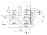
- Fig.2
- Draufsicht auf einen vergrößerten Abschnitt des Laufstreifenprofils von
Fig.1 , - Fig.3
- das Laufstreifenprofil von
Fig.1 in Schnittdarstellung gemäß Schnitt III-III vonFig.1 , - Fig.4
- das Laufstreifenprofil von
Fig.1 in Schnittdarstellung gemäß Schnitt IV-IV vonFig.1 , - Fig.5
- das Laufstreifenprofil von
Fig.1 in Schnittdarstellung gemäß Schnitt V-V vonFig.1 , - Fig.6
- das Laufstreifenprofil von
Fig.1 in Schnittdarstellung gemäß Schnitt VI-VI vonFig.1 , - Fig.7
- das Laufstreifenprofil von
Fig.1 in Schnittdarstellung gemäß Schnitt VII-VII vonFig.1 .
- Fig.1
- a plan view of a portion of a tread pattern of a passenger car pneumatic tire with peripheral ribs,
- Fig.2
- Top view of an enlarged portion of the tread pattern of
Fig.1 . - Figure 3
- the tread pattern of
Fig.1 in section according to section III-III ofFig.1 . - Figure 4
- the tread pattern of
Fig.1 in section according to section IV-IV ofFig.1 . - Figure 5
- the tread pattern of
Fig.1 in section according to section VV ofFig.1 . - Figure 6
- the tread pattern of
Fig.1 in section according to section VI-VI ofFig.1 . - Figure 7
- the tread pattern of
Fig.1 in section according to section VII-VII ofFig.1 ,
Die
Die Umfangsrillen 5, 6 und 7 sind in radialer Richtung R des Fahrzeugluftreifens nach innen hin jeweils von einem Rillengrund 23 begrenzt, welcher über den gesamten Umfang des Fahrzeugluftreifens erstreckt ausgebildet ist. Die Umfangsrippen 2 und 3 sind in radialer Richtung R nach außen hin von einer die Bodenkontaktoberfläche bildenden Oberfläche 8 begrenzt, welche sich jeweils über den gesamten Umfang des Fahrzeugluftreifens in Umfangsrichtung U und bei der Umfangsrippe 3 in axialer Richtung A von der Umfangsrille 6 bis zur Umfangsrille 7 hin und bei der Umfangsrippe 2 in axialer Richtung A von der Umfangsrille 5 bis zur Umfangsrille 6 hin erstreckt. Die Umfangsrille 5 ist in axialer Richtung A zur Umfangsrippe 2 hin durch eine Rillenwand begrenzt, welche die zur Umfangsrille 5 hin gerichtete Flanke der Umfangsrippe 2 bildet, und zur Schulterprofilblockreihe 1 hin durch eine Rillenwand, welche die zur Umfangsrille 5 hin gerichtete Flanke der Schulterprofilblockreihe 1 bildet. Die Umfangsrille 6 ist in axialer Richtung A zur Umfangsrippe 2 hin durch eine Rillenwand begrenzt, welche die zur Umfangsrille 6 hin gerichtete Flanke der Umfangsrippe 2 bildet, und zur Umfangsrippe 3 hin durch eine Rillenwand, welche die zur Umfangsrille 6 hin gerichtete Flanke 9 der Umfangsrippe 3 bildet. Die Umfangsrille 7 ist zur Umfangsrippe 3 hin durch eine Rillenwand begrenzt, welche die zur Umfangsrille 7 hin gerichtete Flanke 10 der Umfangsrippe 3 bildet, und zur Schulterprofilblockreihe 4 hin durch eine Rillenwand, welche die zur Umfangsrille 7 hingerichtete Flanke der Schulterprofilblockreihe 4 bildet. Die Flanke 9 der Umfangsrippe 3 erstreckt sich in radialer Richtung R aus dem Rillengrund 23 der Umfangsrille 6 bis zur radial äußeren Oberfläche 8 der Umfangsrippe 3. Ebenso erstreckt sich die Flanke 10 der Umfangsrippe 3 aus dem Rillengrund 23 der Umfangsrille 7 in radialer Richtung R bis zur radialen äußeren Oberfläche 8 der Umfangsrippe 3. Entsprechend erstrecken sich die beiden die Umfangsrippe 2 begrenzenden Flanken jeweils aus dem Rillengrund 23 der jeweils zugeordneten Umfangsrille 5 bzw. 6 in radialer Richtung R bis zu der die Umfangsrippe 2 nach radial außen hin begrenzenden Oberfläche 8.The
Die Umfangsrippe 3 und die Umfangsippe 2 ist jeweils in axialer Richtung A mit einer Breite B ausgebildet, welche in der radial äußeren Oberfläche 8 bemessen wird.The
In der Umfangsrippe 3 ist - wie in den
Bei Ausbildung eines Reifens in bekannter Weise mit einer Pitchfolgenausbildung des Profils ist der Pitchfolgenverteilung entsprechend die Wellenlänge L1 über den Umfang des Fahrzeugluftreifens hinweg alternierend ausgebildet. Zwischen zwei in Umfangsrichtung U hintereinander angeordnet ausgebildeten Schnittpunkten S1 ist jedoch auch dann die Wellenlänge beider Feineinschnitte 12 und 13 jeweils gleich groß.When forming a tire in a known manner with a pitch sequence formation of the profile, the pitch sequence distribution is correspondingly formed alternately over the wavelength L 1 over the circumference of the pneumatic vehicle tire. However, between two circumferentially arranged in U successively arranged intersection points S 1 , the wavelength of both
Die Feineinschnitte 12 und 13 sind dabei längs ihrer Erstreckung in Umfangsrichtung U mit einer gemessen von der radial äußeren Oberfläche 8 der Umfangsrippe 3 in radialer Richtung R nach innen gemessenen Tiefe t2 ausgebildet.The
Wie in
Wie den
Das Paar 14 von wellenförmigen Feineinschnitten 15 und 16 ist dabei derart ausgebildet, dass sich die Feineinschnitte 15 und 16 jeweils um eine in axialer Richtung A ausgerichtete Nulldurchgangslinie 21 wellenförmig erstrecken, wobei die Wellenform der Feineinschnitte 15 und 16 eine Wellenlänge L2 aufweist mit (L2)/2 > B. Die Wellenform der Feineinschnitte 15 und 16 ist dabei in axialer Richtung A des Fahrzeugluftreifens um einen Phasenwinkel π versetzt zueinander ausgebildet, so dass sich die beiden Feineinschnitte 15 und 16 jeweils in auf der Nulldurchgangslinie 21 im Abstand (L2/2) voneinander ausgebildeten Schnittpunkten S2 schneiden. Die Wellenform der Feineinschnitte 15 und 16 ist dabei jeweils mit gleicher von der Nulldurchgangslinie 21 in Umfangsrichtung U gemessenen Amplitude H2 ausgebildet. Der Feineinschnitt 15 weist in seiner Wellenform jeweils ein Maximum in gleicher axialer Position auf, in der der Feineinschnitt 16 ein Minimum aufweist. Der Feineinschnitt 15 weist in seiner Wellenform jeweils in gleicher axialer Position ein Minimum auf, in der die Wellenform des Feineinschnitts 16 ein Maximum aufweist. Die Schnittpunkte S2 sind dabei außerhalb der Umfangsrippen 2 und 3 ausgebildet, wobei ein Schnittpunkt S2 der Wellenformen der Feineinschnitte 15 und 16 im Erstreckungsbereich der Umfangsrille 6, ein Schnittpunkt S2 im Erstreckungsbereich der Umfangsrille 5 und ein Schnittpunkt S2 im Erstreckungsbereich der Umfangsrille 7 ausgebildet ist. Diese Schnittpunkte S2 sind dabei in der axialen Verlängerung der radial äußeren Oberfläche 8 in diese jeweilige Umfangsrille 5, 6 bzw. 7 hinein ausgebildet.The
Die Schnittpunkte S1 des Paars 11 der in Umfangsrichtung U ausgerichteten wellenförmigen Feineinschnitte 12 und 13 sind dabei jeweils in der axialen Position der Maxima bzw. Minima der Wellenform der Feineinschnitte 15 und 16 des Paars von Feineinschnitten 14 zwischen den beiden Feineinschnitten 15 und 16 eines Paares 14 ausgebildet.The points of intersection S 1 of the
Zwischen zwei in Umfangsrichtung U hintereinander angeordneten Paaren 14 von Feineinschnitten 15 und 16 ist jeweils ein Paar 17 von Feineinschnitten 18 und 19 ausgebildet, welche ebenfalls in axialer Richtung A des Fahrzeugluftreifens ausgerichtet und wellenförmig um eine in axialer Richtung A ausgerichtete gemeinsame Nulldurchgangslinie 22 verlaufend ausgebildet sind. Die beiden Feineinschnitte 18 und 19 eines Paares 17 von Feineinschnitten sind dabei jeweils mit gleicher in axialer Richtung A gemessener Wellenlänge L3 und mit jeweils gleicher von der Nulldurchgangslinie 22 in Umfangsrichtung U gemessenen Amplitude H3 ausgebildet. Die Feineinschnitte 18 und 19 sind dabei mit ihrer Wellenform derart ausgebildet, dass sie in axialer Richtung A um einen Phasenwinkel π versetzt zueinander ausgebildet sind und sich jeweils entlang der axialen Erstreckung der Nulldurchgangslinie 22 in auf der Nulldurchgangslinie 22 ausgebildeten Schnittpunkten S3 schneiden. Dabei ist jeweils genau ein Schnittpunkt S3 eines Paares 17 von Feineinschnitten 18 und 19 in der radial äußeren Oberfläche 8 der Umfangsrippe 2 und genau ein Schnittpunkt S3 eines Paares 17 von Feineinschnitten 18 und 19 in der radial äußeren Oberfläche 8 der Umfangsrippe 3 ausgebildet. Die Schnittpunkte S3 der Paare 17 von Feineinschnitten 18 und 19 in der Umfangsrippe 3 liegen dabei in gleicher axialer Position wie die Schnittpunkte S1 des Paares 11 von in Umfangsrichtung U ausgerichteten Feineinschnitten 12 und 13. Ebenso liegen die Schnittpunkte S3 der Umfangsrippe 2 in gleicher axialer Position wie die Schnittpunkte S1 des Paares 11 von in Umfangsrichtung U ausgerichteten Feineinschnitten 12 und 13 der Umfangsrippe 2. Die Wellenformen der Feineinschnitte 18 und 19 nehmen ihre Maxima bzw. Minima jeweils in axialen Positionen außerhalb der Umfangsrippe 2 und 3 ein. Der Feineinschnitt 18 und der Feineinschnitt 19 weist sowohl in der Umfangsrille 6 als auch in der Umfangsrille 5 als auch in der Umfangsrille 7 jeweils einen Extremwert seiner Wellenform auf, welcher in gleicher axialer Position ausgebildet wie die Schnittpunkte S2 der Wellenform der Feineinschnitte 15 und 16.Between two circumferentially U successively arranged
Die Wellenlängen L2 und die Wellenlänge L3 ist mit L2 = L3 gewählt. Die Phase der Wellenform des Feineinschnitts 15 des Paares 14 ist in axialer Richtung A gegenüber der Phase der Wellenform des Feineinschnittes 18 des Phasenpaares 17 um einen Phasenwinkel (π/2) verschoben. Die Phase der Wellenform des Feineinschnittes 16 des Paares 14 ist in axialer Richtung A gegenüber der Wellenform des Feineinschnitt 19 des Paares 17 um einen Phasenwinkel (π/2) verschoben.The wavelengths L 2 and the wavelength L 3 is selected with L 2 = L 3 . The phase of the waveform of the
Wie den
Die axiale Erstreckung b1, b2, b3 und b4 ist dabei jeweils mit b1 ≥ (0,25 B), b2 ≥ (0,25 B), b3 ≥ (0,25 B) und b4 ≥ (0,25 B) ausgebildet.The axial extent b 1 , b 2 , b 3 and b 4 is in each case with b 1 ≥ (0.25 B), b 2 ≥ (0.25 B), b 3 ≥ (0.25 B) and b 4 ≥ (0.25 B) formed.
Im dargestellten Ausführungsbeispiel ist die Tiefe t1 mit t1 = PT ausgebildet. Beispielsweise ist t1 = PT = 7mm ausgebildet. Die Tiefe t2 ist mit (0,1 PT) ≤ t2 ≤ (0,4 PT) ausgebildet. Die Tiefe t2 ist mit 1mm ≤ t2 ≤ 3mm - beispielsweise mit t2 = 1,5 mm - ausgebildet.In the illustrated embodiment, the depth t 1 is formed with t 1 = P T. For example, t 1 = P T = 7mm is formed. The depth t 2 is formed with (0.1 P T ) ≦ t 2 ≦ (0.4 P T ). The depth t 2 is formed with 1 mm ≦ t 2 ≦ 3 mm, for example, with t 2 = 1.5 mm.
Auf diese Weise ist jeweils in der Umfangsrippe 3 bzw. in der Umfangsrippe 2 sowohl in dem axialen Erstreckungsabschnitt zwischen Umfangsrille 7 und dem Paar 11 von in Umfangsrichtung ausgerichteten Feineinschnitten 12 und 13 jeweils über den Umfang des Fahrzeugluftreifens hinweg in alternierender Reihenfolge ein axialer Erstreckungsabschnitt eines gekrümmten Feineinschnittes mit der Tiefe t2 und der in Umfangsrichtung U nachfolgend angeordnete axiale Erstreckungsabschnitt eines gekrümmten Feineinschnittes mit der Tiefe t1 ausgebildet. Ebenso ist in dem axialen Erstreckungsabschnitt zwischen der Umfangsrille 6 und dem Paar 11 von in Umfangsrichtung erstreckten Feineinschnitten 12 und 13 jeweils über den Umfang des Fahrzeugluftreifens hinweg in alternierender Reihenfolge ein axialer Erstreckungsabschnitt eines gekrümmten Feineinschnitt mit der Tiefe t1 und der in Umfangsrichtung nachfolgend angeordnete axiale Erstreckungsabschnitt eines gekrümmten Feineinschnittes mit der Tiefe t2 ausgebildet. Dabei ist in der Umfangsrippe 3 jeweils in der Umfangsposition, in der ein auf der rechten zur Umfangsrille 7 hin ausgebildeter Erstreckungsabschnitt eines Feineinschnitts mit der Tiefe t2 ausgebildet ist, der links zur Umfangsrille 6 hin ausgebildete Erstreckungsabschnitt mit der Tiefe t1 ausgebildet und umgekehrt. Somit ergibt sich über den Umfang des Fahrzeugluftreifens hinweg, dass die Umfangsrippe 3 mit ihren Feineinschnitten 12,13,15,16,18 und 19 im Wesentlichen mit den Feineinschnitttiefen t2 ausgebildet ist, jedoch in den äußeren zu den Umfangsrillen 6 und 7 hin erstreckten axialen Erstreckungsbereichen der in axialer Richtung A ausgerichteten Feineinschnitte 15,16,18 und 19 jeweils mit einem mit in Umfangsrichtung U in alternierender Reihenfolge mit wechselnder Tiefe t1 und t2 ausgebildeten Erstreckungsabschnitten von Feineinschnitten. Die Positionen der axialen Erstreckungsbereiche von Feineinschnitten, die mit der Tiefe t1 ausgebildet sind, sind auf der rechten zur Umfangsrille 7 hin ausgebildeten Seite jeweils in Umfangsrichtung U zu den entsprechenden Positionen der axialen Erstreckungsbereiche von Feineinschnitten, die mit der Tiefe t1 ausgebildet sind, auf der linken zur Umfangsrille 6 hin ausgebildeten Seite versetzt angeordnet. Die Positionen der axialen Erstreckungsbereiche von Feineinschnitten, die mit der Tiefe t2 ausgebildet sind, sind auf der rechten zur Umfangsrille 7 hin ausgebildeten Seite jeweils in Umfangsrichtung U zu den entsprechenden Positionen der axialen Erstreckungsbereiche von Feineinschnitten, die mit der Tiefe t2 ausgebildet sind, auf der linken zur Umfangsrille 6 hin ausgebildeten Seite versetzt angeordnet.In this way, in each of the
Die
In einem Ausführungsbeispiel ist beispielsweise a = 2mm ausgebildet.In one exemplary embodiment, for example, a = 2 mm is formed.
In einem nicht dargestellten Ausführungsbeispiel ist der Rillengrund 23 der Umfangsrillen 5, 6 und 7 um ein Maß t3 gegenüber dem der Profiltiefe PT angehoben. In diesem Ausführungsbeispiel sind die Feineinschnitte 15, 16, 18 und 19 jeweils im Rillengrund 23 noch mit einer gegenüber dem Rillengrund 23 nach radial innen erstreckt ausgebildeten radialen Tiefe t3 bis zur Erreichung des tiefsten Punktes der Profiltiefe PT fortgeführt.In one embodiment, not shown, the
Dabei ist die Tiefe t3 mit t3 ≤ 0,1 PT ausgebildet. Beispielsweise ist t3 = 0,5 mm ausgebildet.In this case, the depth t 3 is formed with t 3 ≦ 0.1 P T. For example, t 3 = 0.5 mm is formed.
- 11
- SchulterblockreiheShoulder block row
- 22
- Umfangsrippecircumferential rib
- 33
- Umfangsrippecircumferential rib
- 44
- SchulterprofilblockreiheShoulder profile block row
- 55
- Umfangsrillecircumferential groove
- 66
- Umfangsrillecircumferential groove
- 77
- Umfangsrillecircumferential groove
- 88th
- Radial äußere OberflächeRadially outer surface
- 99
- Flankeflank
- 1010
- Flankeflank
- 1111
- Paar von umfangsorientierten FeineinschnittenPair of circumferential sinews
- 1212
- Feineinschnittsipe
- 1313
- Feineinschnittsipe
- 1414
- Paar von axial orientierten FeineinschnittenPair of axially oriented sipes
- 1515
- Feineinschnittsipe
- 1616
- Feineinschnittsipe
- 1717
- Paar von axial orientierten FeineinschnittenPair of axially oriented sipes
- 1818
- Feineinschnittsipe
- 1919
- Feineinschnittsipe
- 2020
- NulldurchgangslinieZero crossing line
- 2121
- NulldurchgangslinieZero crossing line
- 2222
- NulldurchgangslinieZero crossing line
- 2323
- Rillengrundgroove bottom
Claims (15)
dass die zwischen dem zu einer Umfangsrille (6,7) jeweils nächstgelegenen in Umfangsrichtung U ausgerichteten Feineinschnitt (12,13) des Netzes und der Umfangsrille (6,7) ausgebildeten axialen Erstreckungsabschnitte der querverlaufenden Feineinschnitte (15,16,18,19) mit einer unterschiedlichen in radialer Richtung R gemessenen maximalen Tiefe mit wenigstens zwei unterschiedlichen maximalen Tiefen t1 und t2 mit t1 > t2 ausgebildet sind, wobei die axialen Erstreckungsabschnitte der Feineinschnitte (15,16,18,19) unterschiedlicher Tiefenausbildung in Umfangsrichtung U des Fahrzeugluftreifens in alternierender Abfolge angeordnet sind, und
dass der in dem zwischen den beiden jeweils zu einer der beiden Umfangsrillen (6,7) nächstgelegenen und in Umfangsrichtung U ausgerichteten Feineinschnitt (12,13) des Netzes ausgebildete axiale Erstreckungsabschnitt der querverlaufenden Feineinschnitte (15,16,18,19) mit der kleineren t2 der wenigstens zwei Tiefen der Feineinschnitte (15,16,18,19) ausgebildet ist.Tread pattern of a pneumatic vehicle tire with over the circumference of the tire extending profile bands (2,3) - such as circumferential ribs or tread block rows - which are arranged between two circumferential grooves (5,6,7), wherein the profiled strips (3) in the axial direction A to a circumferential groove (6, 7) delimiting the profiled strip (3) is bounded in each case by a flank (9, 10) which forms the groove wall of the circumferential groove (6, 7) facing the profiled strip (3), and wherein the profiled strips (3) in the radial direction R are bounded outwardly by a radially outer surface (8) forming the ground contact surface, with a network of sipes in the radially outer surface (8) of at least one profiled strip (3) consisting of sipes substantially aligned in the circumferential direction U. (12,13) and from these sipes (12,13) intersecting, extending from the one circumferential groove (6) to the other circumferential groove (7), transverse sipes (15,16, 18, 19) is formed, characterized
in that the axial extension sections of the transverse sipes (15, 16, 18, 19) formed between the fine sipe (12, 13) of the net and the circumferential groove (6, 7), which are respectively oriented in the circumferential direction U to form a circumferential groove (6, 7) a different maximum depth measured in the radial direction R with at least two different maximum depths t 1 and t 2 with t 1 > t 2 are formed, wherein the axial extension sections of the sipes (15,16,18,19) of different depth formation in the circumferential direction U of Pneumatic vehicle tire are arranged in an alternating sequence, and
in that the axial extension section of the transverse sipes (15, 16, 18, 19), which is closest to the one of the two circumferential grooves (6, 7) and is oriented in the circumferential direction U of the net, forms the smaller one t 2 of the at least two depths of the sipes (15,16,18,19) is formed.
wobei die querverlaufenden Feineinschnitte (15,16,18,19) des Netzes in dem zwischen dem zu einer Umfangsrille (6,7) jeweils nächstgelegenen in Umfangsrichtung U ausgerichteten Feineinschnitt (12,13) des Netzes und der Umfangsrille (6,7) ausgebildeten axialen Erstreckungsabschnitt, welche in dem Erstreckungsabschnitt mit maximaler Tiefe t2 ausgebildet sind, in dem gesamten axialen Erstreckungsabschnitt zwischen dem der Umfangsrille (6,7) nächstgelegenen in Umfangsrichtung U ausgerichteten Feineinschnitt (12,13) des Netzes und dieser Umfangsrille (6,7) mit der Tiefe t2 ausgebildet sind.Tread pattern according to the features of claim 1,
the transverse sipes (15, 16, 18, 19) of the net being formed in the net between the sipe (12, 13) of the net and the circumferential groove (6, 7) which are respectively closest to a circumferential groove (6, 7) Axial extension portion, which are formed in the extension portion with maximum depth t 2 , in the entire axial extension portion between the circumferential groove (6,7) nearest in the circumferential direction U aligned sipe (12,13) of the network and this circumferential groove (6,7) are formed with the depth t 2 .
wobei die in dem zur einen Umfangsrille (6,7) hin angrenzenden mit der größeren Tiefenausbildung t1 ausgebildeten axialen Erstreckungsabschnitte querverlaufender Feineinschnitte (15,16,18,19) des Netzes in Umfangsrichtung U zwischen den zur anderen Umfangsrille (6,7) hin angrenzenden mit der größeren Tiefenausbildung t1 ausgebildeten axialen Erstreckungsabschnitten von querverlaufenden Feineinschnitten (15,16,18,19) angeordnet sind.Tread pattern according to the features of claim 1 or 2,
wherein the in the one circumferential groove (6,7) adjacent to the greater depth education t 1 formed axial extension portions of transverse sipes (15,16,18,19) of the network in the circumferential direction U between the other circumferential groove (6,7) out adjacent to the greater depth education t 1 formed axial extension portions of transverse sipes (15,16,18,19) are arranged.
wobei die in der radial äußeren Oberfläche (8) ausgebildeten Feineinschnitte des Netzes des Profilbandes (3) Paare (14) von in Umfangsrichtung U hintereinander benachbart angeordneten in axialer Richtung A erstreckten Feineinschnitten (15,16) aufweisen mit einem in der radial äußeren Oberfläche (8) längs der axialen Erstreckung von der einen Umfangsrille (6) zur anderen Umfangsrille (7) entgegengesetzt zueinander gekrümmtem Verlauf.Tread pattern according to the features of one or more of the preceding claims,
wherein the in the radially outer surface (8) formed sipes of the network of the profile strip (3) pairs (14) of circumferentially U adjacent to each other arranged in the axial direction A extending fine incisions (15,16) having a in the radially outer surface ( 8) along the axial extent of the one circumferential groove (6) to the other circumferential groove (7) opposite to each other curved course.
wobei in der radial äußeren Oberfläche (8) des Profilbandes (3) das Netz mit zwei unterschiedlichen Paaren (14,17) von in Umfangsrichtung U hintereinander benachbart angeordneten Feineinschnitten (15,16,18,19) mit einem in der radial äußeren Oberfläche (8) längs der axialen Erstreckung von der einen Umfangsrille (6) zur anderen Umfangsrille (7) entgegengesetzt gekrümmtem Verlauf ausgebildet sind, welche über den Umfang des Reifens verteilt in alternierender Reihenfolge angeordnet sind.Tread pattern according to the features of claim 4,
wherein in the radially outer surface (8) of the profile strip (3) the net with two different pairs (14,17) of circumferentially U successively arranged adjacent sipes (15,16,18,19) with a radially in the outer surface (8) are formed along the axial extent of the one circumferential groove (6) to the other circumferential groove (7) opposite curved course, which are distributed over the circumference of the tire arranged in an alternating sequence.
wobei der gekrümmte Verlauf beider Feineinschnitte (15,16,18,19) eines Paares (14,17) jeweils einen Abschnitt einer in axialer Richtung A erstreckten Wellenform mit in Umfangsrichtung U gemessener Amplitude bildet.Tread pattern according to the features of claim 4 or 5,
wherein the curved course of both sipes (15,16,18,19) of a pair (14,17) each forms a portion of a waveform extending in the axial direction A with amplitude measured in the circumferential direction U.
wobei der gekrümmte Verlaufbeider Feineinschnitte (15,16,18,19) eines Paares (14,17) jeweils einen zu einander phasenversetzten Abschnitt einer Wellenform gleicher Wellenlänge (L2,L3) bildet.Tread pattern according to the features of claim 6,
wherein the curved course of each of the sipes (15, 16, 18, 19) of a pair (14, 17) each forms a mutually phase-shifted portion of a waveform of the same wavelength (L 2 , L 3 ).
wobei der gekrümmte Verlauf beider Feineinschnitte eines Paares jeweils einen zu einander phasenversetzten Abschnitt einer Wellenform gleicher in Umfangsrichtung U gemessener Amplitude bildet.Tread pattern according to the features of claim 6 or 7,
wherein the curved course of both sipes of a pair each form a mutually phase-shifted portion of a waveform equal amplitude measured in the circumferential direction U.
wobei die Phase des einen Feineinschnitts (15,18) eines Paares gegenüber der des anderen Feineinschnitts (16,19) um einen Phasenwinkel π versetzt ist.Tread pattern according to the features of one or more of claims 6, 7 or 8,
wherein the phase of the one fine cut (15, 18) of one pair is offset from the other one of the fine cuts (16, 19) by a phase angle π.
wobei die Phase des einen Feineinschnitts (15) des ersten Paares (14) gegenüber dem einen Feineinschnitt (18) des zweiten Paares (17) um einen Phasenwinkel
(π /2) und die Phase des zweiten Feineinschnitts (16) des ersten Paares (14) gegenüber dem zweiten Feineinschnitt (19) des zweiten Paares (17) um einen Phasenwinkel (π /2) versetzt ausgebildet ist.Tread pattern according to the features of claims 5, 6 and 8,
wherein the phase of the one fine incision (15) of the first pair (14) with respect to the one fine incision (18) of the second pair (17) by a phase angle
(π / 2) and the phase of the second sipe (16) of the first pair (14) relative to the second sipe (19) of the second pair (17) by one Phase angle (π / 2) is formed offset.
wobei die beiden Feineinschnitte (18,19) des zweiten Paares (17) sich in der radial äußeren Oberfläche (8) des Profilbandes (7) - insbesondere in ihrem Wendepunkt - schneiden.Tread pattern according to the features of claim 10,
wherein the two sipes (18,19) of the second pair (17) in the radially outer surface (8) of the profile strip (7) - in particular in its inflection point - intersect.
wobei die beiden Feineinschnitte (15,16) des ersten Paares (14) sich in der radial äußeren Oberfläche (8) des Profilbandes (3) nicht schneiden.Tread pattern according to the features of claim 10,
wherein the two sipes (15,16) of the first pair (14) do not intersect in the radially outer surface (8) of the profile strip (3).
wobei die beiden Feineinschnitte (15,16) eines Paares (14) in Verlängerung ihres wellenförmigen Verlaufes in axialer Richtung A des Reifens über eine das Profilband (3) begrenzende Umfangsrille (6) hinweg ein entsprechendes Paar (14) von Feineinschnitten (15,16) in der radial äußeren Oberfläche (8) eines weiteren durch die Umfangsrille (6) begrenzten Profilbandes (2) bildet.Tread pattern according to the features of one or more of the preceding claims 6 to 12,
wherein the two sipes (15,16) of a pair (14) in extension of its undulating course in the axial direction A of the tire over a the profile band (3) limiting circumferential groove (6) of time a corresponding pair (14) of sipes (15,16 ) in the radially outer surface (8) of a further by the circumferential groove (6) limited profile strip (2).
wobei in der radial äußeren Oberfläche (8) des Profilbandes (3) das Netz mit einem Paar (11) von wellenförmig in Umfangsrichtung U ausgerichteten Feineinschnitten (12,13) mit gleicher Wellenlänge (L1) und mit längs der Erstreckung in Umfangsrichtung U versetzter Phase ausgebildet ist, welches sich insbesondere über den gesamten Umfang des Reifens erstreckt, und
wobei der axiale Abstand der beiden in Umfangsrichtung U ausgerichteten Nulldurchgangslinien der beiden Wellenformen kleiner ist als ihre Amplitude, so dass sich die Feineinschnitte (12,13) über den Umfang des Reifens schneiden.Tread pattern according to the features of one or more of the preceding claims 1 to 13,
wherein in the radially outer surface (8) of the profile strip (3) the network with a pair (11) of undulating aligned in the circumferential direction U fine incisions (12,13) with the same wavelength (L 1 ) and along the extension in the circumferential direction U offset Phase is formed, which extends in particular over the entire circumference of the tire, and
wherein the axial distance of the two circumferentially U-aligned zero-crossing lines of the two waveforms is smaller than their amplitude, so that the sipes (12,13) intersect over the circumference of the tire.
wobei die Schnittpunkte S1 der Feineinschnitte (12,13) des weiteren Paars (11) von wellenförmig in Umfangsrichtung U ausgerichteten Feineinschnitten (12,13) zwischen den beiden Feineinschnitten (15,16) eines ersten Paares (14) von in axialer Richtung A erstreckten Feineinschnitten (15,16) ausgebildet ist.Tread pattern according to the features of claim 14,
wherein the points of intersection S 1 of the sipes (12,13) of the further pair (11) of fins aligned in the circumferential direction U fine incisions (12,13) between the two sipes (15,16) of a first pair (14) of the axial direction A. extending fine sipes (15,16) is formed.
Applications Claiming Priority (1)
| Application Number | Priority Date | Filing Date | Title |
|---|---|---|---|
| DE201110052316 DE102011052316A1 (en) | 2011-08-01 | 2011-08-01 | Tread pattern of a pneumatic vehicle tire |
Publications (2)
| Publication Number | Publication Date |
|---|---|
| EP2554404A1 true EP2554404A1 (en) | 2013-02-06 |
| EP2554404B1 EP2554404B1 (en) | 2018-09-12 |
Family
ID=46506262
Family Applications (1)
| Application Number | Title | Priority Date | Filing Date |
|---|---|---|---|
| EP12176038.3A Active EP2554404B1 (en) | 2011-08-01 | 2012-07-12 | Tread band profile of a pneumatic vehicle tyre |
Country Status (2)
| Country | Link |
|---|---|
| EP (1) | EP2554404B1 (en) |
| DE (1) | DE102011052316A1 (en) |
Citations (5)
| Publication number | Priority date | Publication date | Assignee | Title |
|---|---|---|---|---|
| EP0618092A1 (en) * | 1993-04-01 | 1994-10-05 | Semperit Reifen Aktiengesellschaft | Vehicle tyre |
| EP1195271A2 (en) * | 2000-10-06 | 2002-04-10 | Continental Aktiengesellschaft | Vehicle tyre |
| JP2002283813A (en) * | 2001-03-26 | 2002-10-03 | Toyo Tire & Rubber Co Ltd | Pneumatic radial tire |
| DE102004014007A1 (en) * | 2004-03-23 | 2005-10-13 | Continental Ag | Tire mold lamella for forming fine slits in tread profiles comprises a single grid, net or grating which is mounted in recesses in the vulcanizing tool |
| WO2010133940A1 (en) * | 2009-05-19 | 2010-11-25 | Pirelli Tyre S.P.A. | Tyre for a motor vehicle |
Family Cites Families (1)
| Publication number | Priority date | Publication date | Assignee | Title |
|---|---|---|---|---|
| DE102004014006A1 (en) * | 2004-03-23 | 2005-10-13 | Continental Ag | Vehicle tires |
-
2011
- 2011-08-01 DE DE201110052316 patent/DE102011052316A1/en not_active Withdrawn
-
2012
- 2012-07-12 EP EP12176038.3A patent/EP2554404B1/en active Active
Patent Citations (5)
| Publication number | Priority date | Publication date | Assignee | Title |
|---|---|---|---|---|
| EP0618092A1 (en) * | 1993-04-01 | 1994-10-05 | Semperit Reifen Aktiengesellschaft | Vehicle tyre |
| EP1195271A2 (en) * | 2000-10-06 | 2002-04-10 | Continental Aktiengesellschaft | Vehicle tyre |
| JP2002283813A (en) * | 2001-03-26 | 2002-10-03 | Toyo Tire & Rubber Co Ltd | Pneumatic radial tire |
| DE102004014007A1 (en) * | 2004-03-23 | 2005-10-13 | Continental Ag | Tire mold lamella for forming fine slits in tread profiles comprises a single grid, net or grating which is mounted in recesses in the vulcanizing tool |
| WO2010133940A1 (en) * | 2009-05-19 | 2010-11-25 | Pirelli Tyre S.P.A. | Tyre for a motor vehicle |
Also Published As
| Publication number | Publication date |
|---|---|
| DE102011052316A1 (en) | 2013-02-07 |
| EP2554404B1 (en) | 2018-09-12 |
Similar Documents
| Publication | Publication Date | Title |
|---|---|---|
| EP2133217B1 (en) | Pneumatic tyres for a vehicle | |
| EP1580034B1 (en) | Pneumatic tire | |
| EP2965925B1 (en) | Pneumatic tyres for a vehicle | |
| EP2560830A1 (en) | Pneumatic vehicle tyre | |
| EP2159080B1 (en) | Pneumatic tire | |
| DE102011000851A1 (en) | Tread pattern of a pneumatic vehicle tire | |
| EP2785537B1 (en) | Pneumatic vehicle tyre | |
| EP2570273B1 (en) | Tread of a pneumatic vehicle tyre | |
| DE102008029659A1 (en) | Vehicle tires | |
| EP3122574A1 (en) | Pneumatic vehicle tire | |
| EP3658391A1 (en) | Tread profile of a vehicle tyre | |
| WO2013178464A1 (en) | Vehicle pneumatic tyre | |
| EP2554404B1 (en) | Tread band profile of a pneumatic vehicle tyre | |
| EP2388154B1 (en) | Tread portion of a pneumatic tyre | |
| EP2554405B1 (en) | Tread profile of a vehicle tyre | |
| EP3621822B1 (en) | Tread profile of a vehicle tire | |
| DE102016224803A1 (en) | Vehicle tires | |
| EP3219514A1 (en) | Pneumatic tyres for a vehicle | |
| EP3337679B1 (en) | Pneumatic vehicle tyres | |
| WO2023274469A1 (en) | Pneumatic vehicle tyre | |
| DE102019210431A1 (en) | Pneumatic vehicle tires | |
| DE102019213572A1 (en) | Pneumatic vehicle tires |
Legal Events
| Date | Code | Title | Description |
|---|---|---|---|
| PUAI | Public reference made under article 153(3) epc to a published international application that has entered the european phase |
Free format text: ORIGINAL CODE: 0009012 |
|
| AK | Designated contracting states |
Kind code of ref document: A1 Designated state(s): AL AT BE BG CH CY CZ DE DK EE ES FI FR GB GR HR HU IE IS IT LI LT LU LV MC MK MT NL NO PL PT RO RS SE SI SK SM TR |
|
| AX | Request for extension of the european patent |
Extension state: BA ME |
|
| 17P | Request for examination filed |
Effective date: 20130806 |
|
| RBV | Designated contracting states (corrected) |
Designated state(s): AL AT BE BG CH CY CZ DE DK EE ES FI FR GB GR HR HU IE IS IT LI LT LU LV MC MK MT NL NO PL PT RO RS SE SI SK SM TR |
|
| 17Q | First examination report despatched |
Effective date: 20150327 |
|
| GRAP | Despatch of communication of intention to grant a patent |
Free format text: ORIGINAL CODE: EPIDOSNIGR1 |
|
| STAA | Information on the status of an ep patent application or granted ep patent |
Free format text: STATUS: GRANT OF PATENT IS INTENDED |
|
| RIC1 | Information provided on ipc code assigned before grant |
Ipc: B60C 11/12 20060101AFI20180321BHEP Ipc: B60C 11/03 20060101ALN20180321BHEP |
|
| INTG | Intention to grant announced |
Effective date: 20180424 |
|
| GRAS | Grant fee paid |
Free format text: ORIGINAL CODE: EPIDOSNIGR3 |
|
| GRAA | (expected) grant |
Free format text: ORIGINAL CODE: 0009210 |
|
| STAA | Information on the status of an ep patent application or granted ep patent |
Free format text: STATUS: THE PATENT HAS BEEN GRANTED |
|
| AK | Designated contracting states |
Kind code of ref document: B1 Designated state(s): AL AT BE BG CH CY CZ DE DK EE ES FI FR GB GR HR HU IE IS IT LI LT LU LV MC MK MT NL NO PL PT RO RS SE SI SK SM TR |
|
| REG | Reference to a national code |
Ref country code: GB Ref legal event code: FG4D Free format text: NOT ENGLISH |
|
| REG | Reference to a national code |
Ref country code: CH Ref legal event code: EP |
|
| REG | Reference to a national code |
Ref country code: IE Ref legal event code: FG4D Free format text: LANGUAGE OF EP DOCUMENT: GERMAN |
|
| REG | Reference to a national code |
Ref country code: DE Ref legal event code: R096 Ref document number: 502012013413 Country of ref document: DE |
|
| REG | Reference to a national code |
Ref country code: AT Ref legal event code: REF Ref document number: 1040117 Country of ref document: AT Kind code of ref document: T Effective date: 20181015 |
|
| REG | Reference to a national code |
Ref country code: NL Ref legal event code: MP Effective date: 20180912 |
|
| REG | Reference to a national code |
Ref country code: LT Ref legal event code: MG4D |
|
| PG25 | Lapsed in a contracting state [announced via postgrant information from national office to epo] |
Ref country code: NO Free format text: LAPSE BECAUSE OF FAILURE TO SUBMIT A TRANSLATION OF THE DESCRIPTION OR TO PAY THE FEE WITHIN THE PRESCRIBED TIME-LIMIT Effective date: 20181212 Ref country code: BG Free format text: LAPSE BECAUSE OF FAILURE TO SUBMIT A TRANSLATION OF THE DESCRIPTION OR TO PAY THE FEE WITHIN THE PRESCRIBED TIME-LIMIT Effective date: 20181212 Ref country code: LT Free format text: LAPSE BECAUSE OF FAILURE TO SUBMIT A TRANSLATION OF THE DESCRIPTION OR TO PAY THE FEE WITHIN THE PRESCRIBED TIME-LIMIT Effective date: 20180912 Ref country code: RS Free format text: LAPSE BECAUSE OF FAILURE TO SUBMIT A TRANSLATION OF THE DESCRIPTION OR TO PAY THE FEE WITHIN THE PRESCRIBED TIME-LIMIT Effective date: 20180912 Ref country code: SE Free format text: LAPSE BECAUSE OF FAILURE TO SUBMIT A TRANSLATION OF THE DESCRIPTION OR TO PAY THE FEE WITHIN THE PRESCRIBED TIME-LIMIT Effective date: 20180912 Ref country code: GR Free format text: LAPSE BECAUSE OF FAILURE TO SUBMIT A TRANSLATION OF THE DESCRIPTION OR TO PAY THE FEE WITHIN THE PRESCRIBED TIME-LIMIT Effective date: 20181213 Ref country code: FI Free format text: LAPSE BECAUSE OF FAILURE TO SUBMIT A TRANSLATION OF THE DESCRIPTION OR TO PAY THE FEE WITHIN THE PRESCRIBED TIME-LIMIT Effective date: 20180912 |
|
| PG25 | Lapsed in a contracting state [announced via postgrant information from national office to epo] |
Ref country code: AL Free format text: LAPSE BECAUSE OF FAILURE TO SUBMIT A TRANSLATION OF THE DESCRIPTION OR TO PAY THE FEE WITHIN THE PRESCRIBED TIME-LIMIT Effective date: 20180912 Ref country code: LV Free format text: LAPSE BECAUSE OF FAILURE TO SUBMIT A TRANSLATION OF THE DESCRIPTION OR TO PAY THE FEE WITHIN THE PRESCRIBED TIME-LIMIT Effective date: 20180912 Ref country code: HR Free format text: LAPSE BECAUSE OF FAILURE TO SUBMIT A TRANSLATION OF THE DESCRIPTION OR TO PAY THE FEE WITHIN THE PRESCRIBED TIME-LIMIT Effective date: 20180912 |
|
| PG25 | Lapsed in a contracting state [announced via postgrant information from national office to epo] |
Ref country code: PL Free format text: LAPSE BECAUSE OF FAILURE TO SUBMIT A TRANSLATION OF THE DESCRIPTION OR TO PAY THE FEE WITHIN THE PRESCRIBED TIME-LIMIT Effective date: 20180912 Ref country code: EE Free format text: LAPSE BECAUSE OF FAILURE TO SUBMIT A TRANSLATION OF THE DESCRIPTION OR TO PAY THE FEE WITHIN THE PRESCRIBED TIME-LIMIT Effective date: 20180912 Ref country code: IS Free format text: LAPSE BECAUSE OF FAILURE TO SUBMIT A TRANSLATION OF THE DESCRIPTION OR TO PAY THE FEE WITHIN THE PRESCRIBED TIME-LIMIT Effective date: 20190112 Ref country code: ES Free format text: LAPSE BECAUSE OF FAILURE TO SUBMIT A TRANSLATION OF THE DESCRIPTION OR TO PAY THE FEE WITHIN THE PRESCRIBED TIME-LIMIT Effective date: 20180912 Ref country code: RO Free format text: LAPSE BECAUSE OF FAILURE TO SUBMIT A TRANSLATION OF THE DESCRIPTION OR TO PAY THE FEE WITHIN THE PRESCRIBED TIME-LIMIT Effective date: 20180912 Ref country code: NL Free format text: LAPSE BECAUSE OF FAILURE TO SUBMIT A TRANSLATION OF THE DESCRIPTION OR TO PAY THE FEE WITHIN THE PRESCRIBED TIME-LIMIT Effective date: 20180912 Ref country code: CZ Free format text: LAPSE BECAUSE OF FAILURE TO SUBMIT A TRANSLATION OF THE DESCRIPTION OR TO PAY THE FEE WITHIN THE PRESCRIBED TIME-LIMIT Effective date: 20180912 |
|
| PG25 | Lapsed in a contracting state [announced via postgrant information from national office to epo] |
Ref country code: SK Free format text: LAPSE BECAUSE OF FAILURE TO SUBMIT A TRANSLATION OF THE DESCRIPTION OR TO PAY THE FEE WITHIN THE PRESCRIBED TIME-LIMIT Effective date: 20180912 Ref country code: SM Free format text: LAPSE BECAUSE OF FAILURE TO SUBMIT A TRANSLATION OF THE DESCRIPTION OR TO PAY THE FEE WITHIN THE PRESCRIBED TIME-LIMIT Effective date: 20180912 Ref country code: PT Free format text: LAPSE BECAUSE OF FAILURE TO SUBMIT A TRANSLATION OF THE DESCRIPTION OR TO PAY THE FEE WITHIN THE PRESCRIBED TIME-LIMIT Effective date: 20190112 |
|
| REG | Reference to a national code |
Ref country code: DE Ref legal event code: R097 Ref document number: 502012013413 Country of ref document: DE |
|
| PLBE | No opposition filed within time limit |
Free format text: ORIGINAL CODE: 0009261 |
|
| STAA | Information on the status of an ep patent application or granted ep patent |
Free format text: STATUS: NO OPPOSITION FILED WITHIN TIME LIMIT |
|
| PG25 | Lapsed in a contracting state [announced via postgrant information from national office to epo] |
Ref country code: DK Free format text: LAPSE BECAUSE OF FAILURE TO SUBMIT A TRANSLATION OF THE DESCRIPTION OR TO PAY THE FEE WITHIN THE PRESCRIBED TIME-LIMIT Effective date: 20180912 |
|
| 26N | No opposition filed |
Effective date: 20190613 |
|
| PG25 | Lapsed in a contracting state [announced via postgrant information from national office to epo] |
Ref country code: SI Free format text: LAPSE BECAUSE OF FAILURE TO SUBMIT A TRANSLATION OF THE DESCRIPTION OR TO PAY THE FEE WITHIN THE PRESCRIBED TIME-LIMIT Effective date: 20180912 |
|
| PG25 | Lapsed in a contracting state [announced via postgrant information from national office to epo] |
Ref country code: MC Free format text: LAPSE BECAUSE OF FAILURE TO SUBMIT A TRANSLATION OF THE DESCRIPTION OR TO PAY THE FEE WITHIN THE PRESCRIBED TIME-LIMIT Effective date: 20180912 |
|
| REG | Reference to a national code |
Ref country code: CH Ref legal event code: PL |
|
| GBPC | Gb: european patent ceased through non-payment of renewal fee |
Effective date: 20190712 |
|
| PG25 | Lapsed in a contracting state [announced via postgrant information from national office to epo] |
Ref country code: TR Free format text: LAPSE BECAUSE OF FAILURE TO SUBMIT A TRANSLATION OF THE DESCRIPTION OR TO PAY THE FEE WITHIN THE PRESCRIBED TIME-LIMIT Effective date: 20180912 |
|
| REG | Reference to a national code |
Ref country code: BE Ref legal event code: MM Effective date: 20190731 |
|
| PG25 | Lapsed in a contracting state [announced via postgrant information from national office to epo] |
Ref country code: GB Free format text: LAPSE BECAUSE OF NON-PAYMENT OF DUE FEES Effective date: 20190712 |
|
| PG25 | Lapsed in a contracting state [announced via postgrant information from national office to epo] |
Ref country code: LU Free format text: LAPSE BECAUSE OF NON-PAYMENT OF DUE FEES Effective date: 20190712 Ref country code: BE Free format text: LAPSE BECAUSE OF NON-PAYMENT OF DUE FEES Effective date: 20190731 Ref country code: LI Free format text: LAPSE BECAUSE OF NON-PAYMENT OF DUE FEES Effective date: 20190731 Ref country code: CH Free format text: LAPSE BECAUSE OF NON-PAYMENT OF DUE FEES Effective date: 20190731 |
|
| PG25 | Lapsed in a contracting state [announced via postgrant information from national office to epo] |
Ref country code: IE Free format text: LAPSE BECAUSE OF NON-PAYMENT OF DUE FEES Effective date: 20190712 |
|
| PG25 | Lapsed in a contracting state [announced via postgrant information from national office to epo] |
Ref country code: IT Free format text: LAPSE BECAUSE OF NON-PAYMENT OF DUE FEES Effective date: 20190712 |
|
| REG | Reference to a national code |
Ref country code: AT Ref legal event code: MM01 Ref document number: 1040117 Country of ref document: AT Kind code of ref document: T Effective date: 20190712 |
|
| PG25 | Lapsed in a contracting state [announced via postgrant information from national office to epo] |
Ref country code: AT Free format text: LAPSE BECAUSE OF NON-PAYMENT OF DUE FEES Effective date: 20190712 |
|
| PG25 | Lapsed in a contracting state [announced via postgrant information from national office to epo] |
Ref country code: CY Free format text: LAPSE BECAUSE OF FAILURE TO SUBMIT A TRANSLATION OF THE DESCRIPTION OR TO PAY THE FEE WITHIN THE PRESCRIBED TIME-LIMIT Effective date: 20180912 |
|
| PG25 | Lapsed in a contracting state [announced via postgrant information from national office to epo] |
Ref country code: MT Free format text: LAPSE BECAUSE OF FAILURE TO SUBMIT A TRANSLATION OF THE DESCRIPTION OR TO PAY THE FEE WITHIN THE PRESCRIBED TIME-LIMIT Effective date: 20180912 Ref country code: HU Free format text: LAPSE BECAUSE OF FAILURE TO SUBMIT A TRANSLATION OF THE DESCRIPTION OR TO PAY THE FEE WITHIN THE PRESCRIBED TIME-LIMIT; INVALID AB INITIO Effective date: 20120712 |
|
| PG25 | Lapsed in a contracting state [announced via postgrant information from national office to epo] |
Ref country code: MK Free format text: LAPSE BECAUSE OF FAILURE TO SUBMIT A TRANSLATION OF THE DESCRIPTION OR TO PAY THE FEE WITHIN THE PRESCRIBED TIME-LIMIT Effective date: 20180912 |
|
| PGFP | Annual fee paid to national office [announced via postgrant information from national office to epo] |
Ref country code: FR Payment date: 20220720 Year of fee payment: 11 |
|
| PGFP | Annual fee paid to national office [announced via postgrant information from national office to epo] |
Ref country code: DE Payment date: 20230731 Year of fee payment: 12 |
|
| REG | Reference to a national code |
Ref country code: DE Ref legal event code: R081 Ref document number: 502012013413 Country of ref document: DE Owner name: CONTINENTAL REIFEN DEUTSCHLAND GMBH, DE Free format text: FORMER OWNER: CONTINENTAL REIFEN DEUTSCHLAND GMBH, 30165 HANNOVER, DE |