EP0618092A1 - Vehicle tyre - Google Patents
Vehicle tyre Download PDFInfo
- Publication number
- EP0618092A1 EP0618092A1 EP94890060A EP94890060A EP0618092A1 EP 0618092 A1 EP0618092 A1 EP 0618092A1 EP 94890060 A EP94890060 A EP 94890060A EP 94890060 A EP94890060 A EP 94890060A EP 0618092 A1 EP0618092 A1 EP 0618092A1
- Authority
- EP
- European Patent Office
- Prior art keywords
- tread
- individual elements
- double
- shaped
- profile
- Prior art date
- Legal status (The legal status is an assumption and is not a legal conclusion. Google has not performed a legal analysis and makes no representation as to the accuracy of the status listed.)
- Granted
Links
Images
Classifications
-
- B—PERFORMING OPERATIONS; TRANSPORTING
- B60—VEHICLES IN GENERAL
- B60C—VEHICLE TYRES; TYRE INFLATION; TYRE CHANGING; CONNECTING VALVES TO INFLATABLE ELASTIC BODIES IN GENERAL; DEVICES OR ARRANGEMENTS RELATED TO TYRES
- B60C11/00—Tyre tread bands; Tread patterns; Anti-skid inserts
- B60C11/03—Tread patterns
- B60C11/12—Tread patterns characterised by the use of narrow slits or incisions, e.g. sipes
- B60C11/1204—Tread patterns characterised by the use of narrow slits or incisions, e.g. sipes with special shape of the sipe
- B60C2011/1213—Tread patterns characterised by the use of narrow slits or incisions, e.g. sipes with special shape of the sipe sinusoidal or zigzag at the tread surface
-
- B—PERFORMING OPERATIONS; TRANSPORTING
- B60—VEHICLES IN GENERAL
- B60C—VEHICLE TYRES; TYRE INFLATION; TYRE CHANGING; CONNECTING VALVES TO INFLATABLE ELASTIC BODIES IN GENERAL; DEVICES OR ARRANGEMENTS RELATED TO TYRES
- B60C11/00—Tyre tread bands; Tread patterns; Anti-skid inserts
- B60C11/03—Tread patterns
- B60C11/12—Tread patterns characterised by the use of narrow slits or incisions, e.g. sipes
- B60C11/1236—Tread patterns characterised by the use of narrow slits or incisions, e.g. sipes with special arrangements in the tread pattern
- B60C2011/1245—Tread patterns characterised by the use of narrow slits or incisions, e.g. sipes with special arrangements in the tread pattern being arranged in crossing relation, e.g. sipe mesh
Definitions
- the present invention relates to a vehicle tire intended in particular for winter use with a tread pattern which has tread elements, such as tread blocks or tread bands running in the tire circumferential direction, which are provided with a large number of fine incisions.
- Pneumatic vehicle tires with tread treads have proven themselves very well in recent years, particularly when used in winter driving conditions on snowy or icy surfaces.
- Such a vehicle tire is known for example from AT-B 390.915.
- the tread pattern of this pneumatic vehicle tire has a profile rib running around the center circumferential line of the profile and, to the side of this rib, two rows of blocks composed of tread blocks lined up in the circumferential direction. Both the central rib and the profile blocks in the rows of blocks are each provided with a number of fine incisions running continuously over the block width or the rib width. These fine incisions run essentially parallel to one another and are also essentially equally spaced from one another.
- the fine incisions are also oriented in the axial direction such that they enclose an angle of approximately 30 ° with the axial direction over a large part of their length.
- Tires with such a tread pattern generally have good grip properties.
- the pronounced alignment of the fine incisions in the axial direction means that the tread blocks have a relatively low bending stiffness in the circumferential direction, but rather a rather high bending stiffness in the transverse direction, which impairs the transmission of drive and braking forces and the driving behavior, in particular when cornering.
- the invention is therefore based on the task of designing tread elements in the tread such that, while still having good grip properties, a high bending stiffness is ensured both in the circumferential and in the transverse direction, the measures taken also influencing the bending stiffness in one or the other another direction should be possible.
- profile elements with fine incisions are provided, through which individual elements with an at least approximately double-T-shaped configuration are formed.
- fine incisions are accordingly arranged in profile elements in such a way that that, when viewed from above, they follow at least approximately the contour of a double T-beam.
- these fine incisions form individual elements which have a high bending stiffness both in the circumferential direction and in the axial direction, which gives the entire profile element a high bending stiffness in the circumferential and transverse directions.
- good transmission of drive and braking forces is guaranteed and there is a positive effect on driving behavior.
- the fine incision density in the tread block can still be high to create the desired number of grip edges.
- tread blocks are arranged in the tread pattern, which have a single element with an at least approximately double-T-shaped shape.
- the tread pattern has tread blocks, each of which has a plurality of individual elements with an at least approximately double-T-shaped configuration, with at least two individual elements being arranged such that a bar part is in the space between the bar parts of the second individual element lies. This arrangement allows a higher number of grip edges to be created in a rational manner.
- At least one tread band is arranged in the tread pattern, in which the at least approximately double-T-shaped individual elements are arranged in two rows running in the circumferential direction, the double-T-shaped individual elements being directly adjacent to one another within each row connect and two bar parts of one row in the one row in the circumferential direction immediately consecutive individual elements are arranged with an exact fit between the bar parts of the individual elements of the other row.
- This arrangement is particularly advantageous for a treadmill belt, since the effect of increasing the bending stiffness is very effective.
- the tread block edges or the tread band edges form part of the outer contours of the double-T-shaped individual elements.
- they are within a profile block or a tread band arranged double-T-shaped individual elements at least substantially the same size.
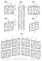
- FIG. 1 shows a top view of a rectangular profile block with a first embodiment of the invention
- FIG. 2 shows a modification of the embodiment according to FIG. 1 for a parallelogram-shaped profile block
- FIG. 3 shows a top view of a section of a profile strip with a further embodiment variant
- 4 and 5 show a further embodiment variant of the invention in a representation analogous to FIGS. 1 and 2
- FIG. 6 shows a schematic plan view of a partial development of a tread pattern designed according to the invention.
- FIGS. 1 and 2 Both drawing figures schematically show a tread block as it can be contained in tread profiles of pneumatic vehicle tires.
- Such profile blocks can have, for example, the rectangular basic shape shown in FIG. 1 or the parallelogram-shaped basic shape shown in FIG. 2.
- the actual block shape in a tread pattern may differ from the simplified basic form of FIGS. 1 and 2 in that the corner edges are bevelled or the profile block edges do not run exactly parallel to one another.
- tread block edges 1a, 1b, 1'a, 1'b has tread block edges 1a, 1b, 1'a, 1'b, the tread block edges 1b, 1'b being those which are aligned in the circumferential direction of the tread pattern Tread block edges 1a would run in the axial direction, and tread block edges 1'a would be inclined at an acute angle with respect to the axial direction of the tire.
- the profile block 1 is provided with a large number of lamellae fine incisions 2 which, viewed in plan view, follow the contour of a plurality of double-T beams nested inside one another.
- the arrangement is such that two double-T beam contours form individual elements, the two beam parts of which run parallel to the block edges 1a and whose connecting webs run parallel to the block edges 1b, two further double-Ts Carrier contours form individual elements, the at least one bar part of which lies in the free space between the bar parts of those individual elements whose connecting webs run in the circumferential direction, that is to say parallel to the block edges 1b.
- the dimensioning of the individual elements in this exemplary embodiment is such that one bar part ends either with the block edges 1a or the block edges 1b.
- Fine cuts 3 possible, especially where it may be appropriate to connect edges of beam parts with profile block edges.
- the fine incisions 2 themselves can extend up to the profile block edges, as a result of which the "beams" are given an asymmetrical shape with respect to the connecting webs.
- All fine incisions 2, 3 have a depth that is preferably at least 30% of the other profile depth.
- the width of these fine incisions 2, 3 is selected in the range between 0.3 and 0.8, in particular between 0.4 and 0.6 mm .
- the arrangement of the fine incisions 2 described creates a fine incision density that is high in the axial direction and in the circumferential direction of the tread pattern. Due to their arrangement in the profile block 1, the fine incisions 2 form elements which have a high bending stiffness both in the circumferential direction and in the axial direction, which transfer to the entire profile block 1, the susceptibility of the profile block 1 to deforming when bending forces occur, which is a bad thing Driving behavior entails significantly reduced.
- the profile block 1 has a large number of grip edges, which is particularly advantageous for tread profiles that are intended to be suitable for winter use.
- the double-T-shaped individual elements shown in FIG. 1 have the same dimensions with each other. Deviating from this illustrated embodiment, however, double-T-shaped individual elements can also be combined with one another, which are of different dimensions. It is also possible to arrange fine incisions in a profile block so that a single double-T-shaped element is formed in the profile block.
- the person skilled in the art has a large number of options for influencing the bending stiffness of the tread block, for example depending on whether it is a block that is closer to the shoulder or in the middle of the tread profile, or the incision density in the circumferential or transverse direction accordingly to change.
- the double-T-shaped individual elements of the fine cuts 2' formed by fine cuts 2 ' have been adapted to the parallelogram shape of the block. Accordingly, in this profile block 1 'fine incisions 2' are present, which create individual elements, the connecting webs of which extend in the circumferential direction and whose beam parts run parallel to the profile block edges 1'a, which are inclined with respect to the axial direction; in the circumferential direction are oriented and the connecting webs are arranged parallel to the profile block edges 1'a.
- This has an impact on the grip properties, since, for example, when driving straight ahead, the traction behavior is influenced by the length components projected in the axial direction of those fine incision sections that run parallel to the profile block edges 1'a.
- tread band 4 shows an arrangement of double-T-shaped individual elements in a tread band 4.
- Such tread bands which run continuously in the circumferential direction, are arranged in particular in the central area of the tread.
- the fine incisions 2 'form in the tread band 4 two rows of double-T-shaped individual elements, these individual elements directly adjoining each other within each row and two bar parts from one row each being arranged with a precise fit between the bar parts of a single element of the other row.
- FIG. 4 The top view of a rectangular profile block 11 is shown in FIG. 4 and a parallelogram-shaped profile block 11 'is shown in FIG. 5.
- the profile block 11 is provided with fine incisions 12.
- the network shown which is formed by the course of the fine incisions 12
- four approximately double-T-shaped individual elements are formed in the profile block 11 in this exemplary embodiment.
- These individual elements result from the fact that both in the axial direction and in the circumferential direction there are provided fine incisions 12 which cross the profile block 11 in wave form, in such a way that adjacent fine incisions 12 have opposing wave forms, so that the troughs and the wave crests are assigned to each other.
- 5 shows this arrangement of the fine incisions 12 'for a parallelogram-shaped profile block 11'.
- FIG. 6 shows a possible embodiment of a tread pattern with tread blocks, which are designed according to the exemplary embodiment according to FIG. 2.
- This tread pattern is designed as a so-called swept or directional profile and is composed of four rows of blocks, each with at least substantially parallelogram-shaped tread blocks 21, through their arrangement three straight circumferential grooves 5 running in the tire circumferential direction and viewed across the tread width B, essentially along V -shaped lateral grooves 6 are formed.
- the present invention is not restricted to the exemplary embodiments shown.
- the arrangement and the number of fine incisions can in particular influence the block profile bending stiffness and the grip behavior.
- sections made according to the invention can have a reduced depth in sections.
Abstract
Description
Die vorliegende Erfindung betrifft einen insbesondere für den Wintereinsatz vorgesehenen Fahrzeugreifen mit einem Laufstreifenprofil, welches Profilelemente, wie Profilblöcke oder in Reifenumfangsrichtung verlaufende Laufstreifenbänder aufweist, die mit einer Vielzahl von Feineinschnitten versehen sind.The present invention relates to a vehicle tire intended in particular for winter use with a tread pattern which has tread elements, such as tread blocks or tread bands running in the tire circumferential direction, which are provided with a large number of fine incisions.
Fahrzeugluftreifen mit Laufstreifenprofilen, deren Profilelemente mit einer Vielzahl von Feineinschnitten versehen sind, haben sich in den letzten Jahren, insbesondere im Einsatz unter winterlichen Fahrbedingungen auf schneeigem oder eisigem Untergrund sehr gut bewährt. Ein derartiger Fahrzeugreifen ist beispielsweise aus der AT-B 390.915 bekannt. Das Laufstreifenprofil dieses Fahrzeugluftreifens besitzt eine entlang der Mittelumfangslinie des Profiles umlaufende Profilrippe sowie seitlich dieser Rippe je zwei sich aus in Umfangsrichtung aneinandergereihten Profilblöcken zusammensetzende Blockreihen. Sowohl die Mittelrippe als auch die Profilblöcke in den Blockreihen sind jeweils mit einer Anzahl von über die Blockbreite bzw. die Rippenbreite durchgehend verlaufenden Feineinschnitten versehen. Diese Feineinschnitte verlaufen im wesentlichen parallel zueinander und sind auch im wesentlichen voneinander gleich beabstandet. Die Feineinschnitte sind ferner in Axialrichtung orientiert, derart, daß sie über einen Großteil ihrer Länge einen Winkel von ca. 30° mit der Axialrichtung einschließen. Reifen mit einem derartigen Laufstreifenprofil haben im allgemeinen gute Griffeigenschaften. Die ausgeprägte Ausrichtung der Feineinschnitte in Axialrichtung bewirkt jedoch, daß die Profilblöcke in Umfangsrichtung eine relativ niedrige Biegesteifigkeit, in Querrichtung jedoch eine eher hohe Biegesteifigkeit aufweisen, was die Übertragung von Antriebs- und Bremskräften sowie das Fahrverhalten, insbesondere beim Kurvenfahren, beeinträchtigt.Pneumatic vehicle tires with tread treads, the tread elements of which are provided with a large number of fine incisions, have proven themselves very well in recent years, particularly when used in winter driving conditions on snowy or icy surfaces. Such a vehicle tire is known for example from AT-B 390.915. The tread pattern of this pneumatic vehicle tire has a profile rib running around the center circumferential line of the profile and, to the side of this rib, two rows of blocks composed of tread blocks lined up in the circumferential direction. Both the central rib and the profile blocks in the rows of blocks are each provided with a number of fine incisions running continuously over the block width or the rib width. These fine incisions run essentially parallel to one another and are also essentially equally spaced from one another. The fine incisions are also oriented in the axial direction such that they enclose an angle of approximately 30 ° with the axial direction over a large part of their length. Tires with such a tread pattern generally have good grip properties. However, the pronounced alignment of the fine incisions in the axial direction means that the tread blocks have a relatively low bending stiffness in the circumferential direction, but rather a rather high bending stiffness in the transverse direction, which impairs the transmission of drive and braking forces and the driving behavior, in particular when cornering.
Die Erfindung hat sich daher die Aufgabe gestellt, im Laufstreifen Profilelemente so zu gestalten, daß bei weiterhin guten Griffeigenschaften eine hohe Biegesteifigkeit sowohl in Umfangs- als auch in Querrichtung gewährleistet ist, wobei durch die gesetzten Maßnahmen auch eine Beeinflussung der Biegesteifigkeit in der einen oder der anderen Richtung möglich sein soll.The invention is therefore based on the task of designing tread elements in the tread such that, while still having good grip properties, a high bending stiffness is ensured both in the circumferential and in the transverse direction, the measures taken also influencing the bending stiffness in one or the other another direction should be possible.
Gelöst wird die gestellte Aufgabe erfindungsgemäß dadurch, daß Profilelemte mit Feineinschnitten vorgesehen sind, durch die Einzelelemente mit einer zumindest annähernd Doppel-T-Träger-förmigen Gestalt gebildet sind.
Nach der Erfindung sind demnach in Profilelementen Feineinschnitte derart angeordnet, daß sie, in Draufsicht betrachtet, zumindest annähernd der Kontur eines Doppel-T-Trägers folgen. Dadurch bilden diese Feineinschnitte Einzelelemente, die eine hohe Biegesteifigkeit sowohl in Umfangsrichtung als auch in Axialrichtung aufweisen, was dem gesamten Profilelement eine hohe Biegesteifigkeit in Umfangs- und in Querrichtung verleiht. Gleichzeitig ist eine gute Übertragung von Antriebs- und von Bremskräften gewährleistet und eine positive Auswirkung auf das Fahrverhalten gegeben. Die Feineinschnittdichte im Profilblock kann zur Schaffung der erwünschten Anzahl von Griffkanten weiterhin hoch sein.The object is achieved according to the invention in that profile elements with fine incisions are provided, through which individual elements with an at least approximately double-T-shaped configuration are formed.
According to the invention, fine incisions are accordingly arranged in profile elements in such a way that that, when viewed from above, they follow at least approximately the contour of a double T-beam. As a result, these fine incisions form individual elements which have a high bending stiffness both in the circumferential direction and in the axial direction, which gives the entire profile element a high bending stiffness in the circumferential and transverse directions. At the same time, good transmission of drive and braking forces is guaranteed and there is a positive effect on driving behavior. The fine incision density in the tread block can still be high to create the desired number of grip edges.
Gemäß einer bevorzugten Ausführungsform der Erfindung sind im Laufstreifenprofil Profilblöcke angeordnet, die ein einziges Einzelelement mit einer zumindest annähernd Doppel-T-Träger-förmigen Gestalt aufweisen.According to a preferred embodiment of the invention, tread blocks are arranged in the tread pattern, which have a single element with an at least approximately double-T-shaped shape.
Bei einer weiteren Ausführungform der Erfindung weist das Laufstreifenprofil Profilblöcke auf, die jeweils mehrere Einzelelemente mit einer zumindest annähernd Doppel-T-Träger-förmigen Gestalt aufweisen, wobei jeweils zumindest zwei Einzelelemente derart angeordnet sind, daß ein Balkenteil im Freiraum zwischen den Balkenteilen des zweiten Einzelelementes liegt. Durch diese Anordnung kann auf rationelle Weise eine höhere Anzahl von Griffkanten geschaffen werden.In a further embodiment of the invention, the tread pattern has tread blocks, each of which has a plurality of individual elements with an at least approximately double-T-shaped configuration, with at least two individual elements being arranged such that a bar part is in the space between the bar parts of the second individual element lies. This arrangement allows a higher number of grip edges to be created in a rational manner.
Bei einer anderen Ausführungsform der Erfindung ist im Laufstreifenprofil zumindest ein Laufstreifenband angeordnet, in welchem die zumindest annähernd Doppel-T-Träger-förmigen Einzelelemente in zwei in Umfangsrichtung verlaufenden Reihen angeordnet sind, wobei innerhalb jeder Reihe die Doppel-T-Träger-Einzelelemnte unmittelbar aneinander anschließen und je zwei Balkenteile von in der einen Reihe in Umfangsrichtung unmittelbar aufeinanderfolgenden Einzelelementen paßgenau zwischen den Balkenteilen der Einzelelemente der anderen Reihe angeordnet sind.In another embodiment of the invention, at least one tread band is arranged in the tread pattern, in which the at least approximately double-T-shaped individual elements are arranged in two rows running in the circumferential direction, the double-T-shaped individual elements being directly adjacent to one another within each row connect and two bar parts of one row in the one row in the circumferential direction immediately consecutive individual elements are arranged with an exact fit between the bar parts of the individual elements of the other row.
Diese Anordnung ist für ein Laufstreifenband besonders vorteilhaft, da dadurch der Effekt der Erhöhung der Biegesteifigkeit sehr gut zum Tragen kommt.This arrangement is particularly advantageous for a treadmill belt, since the effect of increasing the bending stiffness is very effective.
Um möglichst ausgewogene Volumsverhältnisse im Profilblock bzw. im Laufstreifenband zu schaffen ist es ferner von Vorteil, wenn die Profilblockkanten bzw. die Laufstreifenbandkanten zum Teil die Außenkonturen der Doppel-T-Träger-förmigen Einzelelemente bilden.In order to create the most balanced volume ratios in the tread block or in the tread band, it is also advantageous if the tread block edges or the tread band edges form part of the outer contours of the double-T-shaped individual elements.
Bei einer bevorzugten Ausführungsform der Erfindung sind die innerhalb eines Profilblockes oder eines Laufstreifenbandes angeordneten Doppel-T-Träger-förmigen Einzelelemente zumindest im wesentlichen gleich dimensioniert.In a preferred embodiment of the invention, they are within a profile block or a tread band arranged double-T-shaped individual elements at least substantially the same size.
Weitere Merkmale, Vorteile und Einzelheiten der Erfindung werden nun anhand der Zeichnung, die mehrere Ausführungsbeispiele der Erfindung in schematischer Darstellung enthält, beschrieben. Dabei zeigt Fig. 1 eine Draufsicht auf einen rechteckigen Profilblock mit einer ersten Ausführungsform der Erfindung, Fig. 2 eine Abwandlung der Ausführungsform nach Fig. 1 bei einem parallelogrammförmigen Profilblock, Fig. 3 eine Draufsicht auf einen Abschnitt eines Profilbandes mit einer weiteren Ausführungsvariante, Fig. 4 und Fig. 5 eine weitere Ausführungsvariante der Erfindung in zu Fig. 1 und Fig. 2 analoger Darstellung und Fig. 6 eine schematische Draufsicht auf eine Teilabwicklung eines nach der Erfindung gestalteten Laufstreifenprofiles.Further features, advantages and details of the invention will now be described with reference to the drawing, which contains several exemplary embodiments of the invention in a schematic representation. 1 shows a top view of a rectangular profile block with a first embodiment of the invention, FIG. 2 shows a modification of the embodiment according to FIG. 1 for a parallelogram-shaped profile block, FIG. 3 shows a top view of a section of a profile strip with a further embodiment variant, 4 and 5 show a further embodiment variant of the invention in a representation analogous to FIGS. 1 and 2 and FIG. 6 shows a schematic plan view of a partial development of a tread pattern designed according to the invention.
Die erste Ausführungsform der Erfindung wird nun anhand der Figuren 1 und 2 näher erläutert Beide Zeichnungsfiguren zeigen dabei schematisch einen Profilblock, wie er in Laufstreifenprofilen von Fahrzeugluftreifen enthalten sein kann. Solche Profilblöcke können beispielsweise die in Fig. 1 dargestellte rechteckige oder die in Fig. 2 dargestellte parallelogrammförmige Grundgestalt aufweisen. Die tatsächliche Blockform in einem Laufstreifenprofil kann von der vereinfachten Grundgestalt der Figuren 1 und 2 etwa dahingehend abweichen, daß die Eckkanten mit Abschrägungen versehen sind oder die Profilblockkanten nicht exakt parallel zueinander verlaufen. Der in Fig. 1 und Fig. 2 dargestellte Profilblock 1, 1' besitzt Profilblockkanten 1a, 1b, 1'a, 1'b, wobei die Profilblockkanten 1b, 1'b jene sind, die in der Umfangsrichtung des Laufstreifenprofiles ausgerichtet sind, die Profilblockkanten 1a würden in axialer Richtung verlaufen, und die Profilblockkanten 1'a wären gegenüber der Axialrichtung des Reifens unter einem spitzen Winkel geneigt. Der Profilblock 1 ist mit einer Vielzahl von Lamellenfeineinschnitten 2 versehen, die, in Draufsicht betrachtet, der Kontur von mehreren ineinander geschachtelten Doppel-T-Trägern folgen. Dabei ist im vorliegenden Ausführungsbeispiel nach Fig. 1 die Anordnung so getroffen, daß zwei Doppel-T-Träger-Konturen Einzelelemente bilden, deren beide Balkenteile jeweils parallel zu den Blockkanten 1a und deren Verbindungsstege parallel zu den Blockkanten 1b verlaufen, zwei weitere Doppel-T-Träger-Konturen bilden Einzelelemente, deren zumindest einer Balkenteil im Freiraum zwischen den Balkenteilen jener Einzelelemente liegt, deren Verbindungsstege in Umfangsrichtung, also parallel zu den Blockkanten 1b, verlaufen. Die Dimensionierung der Einzelelemente ist in diesem Ausführungsbeispiel so getroffen, daß jeweils ein Balkenteil entweder mit den Blockkanten 1a oder den Blockkanten 1b abschließt. Wie dargestellt, ist eine Kombination mit weiteren Feineinschnitten 3 möglich, und zwar insbesondere dort, wo es zweckmäßig sein kann, Kanten von Balkenteilen mit Profilblockkanten zu verbinden. Es können jedoch die Feineinschnitte 2 selbst bis zu den Profilblockkanten verlaufen, wodurch die "Balken" eine bezüglich der Verbindungsstege asymmetrische Gestalt erhalten.The first embodiment of the invention will now be explained in more detail with reference to FIGS. 1 and 2. Both drawing figures schematically show a tread block as it can be contained in tread profiles of pneumatic vehicle tires. Such profile blocks can have, for example, the rectangular basic shape shown in FIG. 1 or the parallelogram-shaped basic shape shown in FIG. 2. The actual block shape in a tread pattern may differ from the simplified basic form of FIGS. 1 and 2 in that the corner edges are bevelled or the profile block edges do not run exactly parallel to one another. The
Sämtliche Feineinschnitte 2, 3 weisen eine Tiefe auf, die vorzugsweise mindestens 30 % der sonstigen Profiltiefe beträgt Die Breite dieser Feineinschnitte 2, 3 wird im Bereich zwischen 0,3 und 0,8, insbesondere zwischen 0,4 bis 0,6 mm, gewählt. Die geschilderte Anordnung der Feineinschnitte 2 schafft eine Feineinschnittdichte, die in Axialrichtung und in Umfangsrichtung des Laufstreifenprofiles hoch ist. Die Feineinschnitte 2 bilden durch ihre Anordnung im Profilblock 1 Elemente, die eine hohe Biegesteifigkeit sowohl in Umfangsrichtung als auch in Axialrichtung aufweisen, was auf den gesamten Profilblock 1 übertragen, die Anfälligkeit des Profilblockes 1, sich beim Auftreten von Biegekräften zu deformieren, was ein schlechtes Fahrverhalten nach sich zieht, erheblich vermindert. Gleichzeitig hat der Profilblock 1 eine hohe Anzahl von Griffkanten, was insbesondere für Laufstreifenprofile, die für den Wintereinsatz geeignet sein sollen, günstig ist.All
Die in Fig. 1 dargestellten Doppel-T-Träger-förmigen Einzelelemente haben untereinander gleiche Dimensionierung. Abweichend von dieser dargestellten Ausführungsform können jedoch auch Doppel-T-Träger-förmige Einzelelemente miteinander kombiniert werden, die unterschiedlich dimensioniert sind. Dabei ist es ferner möglich, Feineinschnitte in einem Profilblock so anzuordnen, daß im Profilblock ein einziges Doppel-T-Träger-förmiges Element gebildet wird. Hier stehen dem Fachmann eine Vielzahl von Möglichkeiten offen, die Biegesteifigkeit des Profilblockes, beispielsweise je nach dem ob es sich um einen eher in Schulternähe oder in Laufstreifenprofilmitte befindlichen Block handelt, entsprechend zu beeinflussen, oder auch die Einschnittdichte in Umfangs- bzw. in Querrichtung entsprechend zu verändern.The double-T-shaped individual elements shown in FIG. 1 have the same dimensions with each other. Deviating from this illustrated embodiment, however, double-T-shaped individual elements can also be combined with one another, which are of different dimensions. It is also possible to arrange fine incisions in a profile block so that a single double-T-shaped element is formed in the profile block. Here, the person skilled in the art has a large number of options for influencing the bending stiffness of the tread block, for example depending on whether it is a block that is closer to the shoulder or in the middle of the tread profile, or the incision density in the circumferential or transverse direction accordingly to change.
Bei dem in Fig. 2 dargestellten Profilblock 1' sind die durch Feineinschnitte 2' gebildeten Doppel-T-Träger-förmigen Einzelelemente der Feineinschnitte 2' der Parallelogrammform des Blockes angepaßt worden. Demnach sind in diesem Profilblock 1' Feineinschnitte 2' vorhanden, die Einzelelemente schaffen, deren Verbindungsstege in Umfangsrichtung verlaufen und deren Balkenteile parallel zu den gegenüber der Axialrichtung schräggestellten Profilblockkanten 1'a verlaufen, andererseits sind auch, in Draufsicht betrachtet, Einzelelemente geschaffen, deren Balkenteile in Umfangsrichtung orientiert sind und deren Verbindungsstege parallel zu den Profilblockkanten 1'a angeordnet sind. Dies hat Auswirkungen auf die Griffeigenschaften, da etwa bei Geradeausfahrt das Traktionsverhalten von den in die Axialrichtung projezierten Längenkomponenten jener Feineinschnittabschnitte beeinflußt wird, die parallel zu den Profilblockkanten 1'a verlaufen.In the profile block 1 'shown in FIG. 2, the double-T-shaped individual elements of the fine cuts 2' formed by fine cuts 2 'have been adapted to the parallelogram shape of the block. Accordingly, in this profile block 1 'fine incisions 2' are present, which create individual elements, the connecting webs of which extend in the circumferential direction and whose beam parts run parallel to the profile block edges 1'a, which are inclined with respect to the axial direction; in the circumferential direction are oriented and the connecting webs are arranged parallel to the profile block edges 1'a. This has an impact on the grip properties, since, for example, when driving straight ahead, the traction behavior is influenced by the length components projected in the axial direction of those fine incision sections that run parallel to the profile block edges 1'a.
Fig. 3 zeigt eine Anordnung von Doppel-T-Träger-förmigen Einzelelementen in einem Laufstreifenband 4. Derartige, in Umfangsrichtung kontinuierlich umlaufende Laufstreifenbänder werden insbesondere im Laufstreifenmittelbereich angeordnet. Die Feineinschnitte 2' bilden im Laufstreifenband 4 zwei Reihen von Doppel-T-Trägerförmigen Einzelelementen, wobei innerhalb jeder Reihe diese Einzelelemente unmittelbar aneinander anschließen und je zwei Balkenteile aus der einen Reihe paßgenau zwischen den Balkenteilen eines Einzelelementes der anderen Reihe angeordnet sind.3 shows an arrangement of double-T-shaped individual elements in a tread band 4. Such tread bands, which run continuously in the circumferential direction, are arranged in particular in the central area of the tread. The fine incisions 2 'form in the tread band 4 two rows of double-T-shaped individual elements, these individual elements directly adjoining each other within each row and two bar parts from one row each being arranged with a precise fit between the bar parts of a single element of the other row.
Ein weiteres Ausführungsbeispiel der Erfindung wird nun anhand der Figuren 4 und 5 erörtert. Dabei ist in Fig. 4 wiederum die Draufsicht auf einen rechteckförmigen Profilblock 11 und in Fig. 5 auf einen parallelogrammförmigen Profilblock 11' dargestellt. Der Profilblock 11 ist mit Feineinschnitten 12 versehen. Durch das dargestellte Netz, das durch den Verlauf der Feineinschnitte 12 gebildet wird, werden im Profilblock 11 in diesem Ausführungsbeispiel vier annähernd Doppel-T-Träger-förmige Einzelelemente gebildet. Diese Einzelelemente entstehen dadurch, daß sowohl in Axialrichtung als auch in Umfangsrichtung den Profilblock 11 in Wellenform durchquerende Feineinschnitte 12 vorgesehen sind, derart, daß benachbarte Feineinschnitte 12 gegenläufige Wellenformen besitzen, so daß jeweils die Wellentäler und die Wellenberge einander zugeordnet sind. Fig. 5 zeigt diese Anordnung der Feineinschnitte 12' für einen parallelogrammförmigen Profilblock 11'.Another embodiment of the invention will now be discussed with reference to FIGS. 4 and 5. The top view of a
Fig. 6 zeigt eine mögliche Ausgestaltung eines Laufstreifenprofiles mit Profilblöcken, die gemäß dem Ausführungsbeispiel nach Fig. 2 gestaltet sind. Dieses Laufstreifenprofil ist als sogenanntes gepfeiltes bzw. drehrichtungsgebundenes Profil ausgebildet und setzt sich aus vier Blockreihen mit jeweils zumindest im wesentlichen parallelogrammförmigen Profilblöcken 21 zusammen, durch deren Anordnung drei gerade und in Reifenumfangsrichtung verlaufende Umfangsnuten 5 und über die Laufstreifenbreite B betrachtet, im wesentlichen entlang von V-förmigen Kurven verlaufende seitliche Rillen 6 gebildet werden.FIG. 6 shows a possible embodiment of a tread pattern with tread blocks, which are designed according to the exemplary embodiment according to FIG. 2. This tread pattern is designed as a so-called swept or directional profile and is composed of four rows of blocks, each with at least substantially parallelogram-
Es wird darauf verwiesen, daß die vorliegende Erfindung auf die dargestellten Ausführungsbeispiele nicht eingeschränkt ist So ist es insbesondere möglich, die Erfindung auch bei Laufstreifenprofilen einzusetzen, wo Blockreihen mit Laufstreifenbändern kombiniert werden. Dabei ist es selbstverständlich denkbar, bei ein und demselben Laufstreifenprofil eine Kombination von Profilelementen mit nach der Erfindung gestalteten Feineinschnitten mit Profilelementen, die herkömmliche oder andere Feineinschnittgestaltungen aufweisen, vorzusehen. Wie oben erwähnt, können durch die Anordnung und die Anzahl der Feineinschnitte insbesondere die Blockprofilbiegesteifigkeit und das Griffverhalten beeinflußt werden. Es wird schließlich noch darauf verwiesen, daß nach der Erfindung gestaltete Feineinschnitte abschnittsweise eine verringerte Tiefe aufweisen können.It is pointed out that the present invention is not restricted to the exemplary embodiments shown. In particular, it is possible to use the invention in tread patterns where rows of blocks are combined with tread bands. It is of course conceivable to provide a combination of profile elements with fine incisions designed according to the invention with profile elements that have conventional or other fine incision designs in one and the same tread pattern. As mentioned above, the arrangement and the number of fine incisions can in particular influence the block profile bending stiffness and the grip behavior. Finally, reference is made to the fact that sections made according to the invention can have a reduced depth in sections.
Claims (6)
Applications Claiming Priority (2)
| Application Number | Priority Date | Filing Date | Title |
|---|---|---|---|
| AT0066193A AT400554B (en) | 1993-04-01 | 1993-04-01 | VEHICLE TIRES |
| AT661/93 | 1993-04-01 |
Publications (2)
| Publication Number | Publication Date |
|---|---|
| EP0618092A1 true EP0618092A1 (en) | 1994-10-05 |
| EP0618092B1 EP0618092B1 (en) | 1996-07-03 |
Family
ID=3496489
Family Applications (1)
| Application Number | Title | Priority Date | Filing Date |
|---|---|---|---|
| EP94890060A Expired - Lifetime EP0618092B1 (en) | 1993-04-01 | 1994-03-21 | Vehicle tyre |
Country Status (3)
| Country | Link |
|---|---|
| EP (1) | EP0618092B1 (en) |
| AT (2) | AT400554B (en) |
| DE (1) | DE59400386D1 (en) |
Cited By (7)
| Publication number | Priority date | Publication date | Assignee | Title |
|---|---|---|---|---|
| DE19822573C1 (en) * | 1998-05-20 | 1999-10-07 | Continental Ag | Automotive winter tire has enhanced tread |
| EP1080949A2 (en) * | 1999-09-03 | 2001-03-07 | Continental Aktiengesellschaft | Vehicle tyre |
| DE10049936A1 (en) * | 2000-10-06 | 2002-04-25 | Continental Ag | vehicle tires |
| EP1588830A2 (en) * | 2004-03-23 | 2005-10-26 | Continental Aktiengesellschaft | Lamella for the use in a tire vulcanisation mold and method for its production |
| EP1798066A1 (en) | 2005-12-19 | 2007-06-20 | Continental Aktiengesellschaft | Tread profil with net-shaped sipes |
| EP2554405A1 (en) * | 2011-08-01 | 2013-02-06 | Continental Reifen Deutschland GmbH | Tread profile of a vehicle tyre |
| EP2554404A1 (en) * | 2011-08-01 | 2013-02-06 | Continental Reifen Deutschland GmbH | Tread band profile of a pneumatic vehicle tyre |
Citations (3)
| Publication number | Priority date | Publication date | Assignee | Title |
|---|---|---|---|---|
| GB867556A (en) * | 1958-12-31 | 1961-05-10 | Us Rubber Co | Improvements in tread construction and mould |
| GB869980A (en) * | 1958-06-20 | 1961-06-07 | Us Rubber Co | Improvements in slotted tyre tread |
| EP0330643A2 (en) * | 1988-02-24 | 1989-08-30 | Semperit Reifen Aktiengesellschaft | Tread pattern for a pneumatic tyre |
Family Cites Families (2)
| Publication number | Priority date | Publication date | Assignee | Title |
|---|---|---|---|---|
| AT386384B (en) * | 1982-08-04 | 1988-08-10 | Firestone Tire & Rubber Co | MOTOR VEHICLE TIRES |
| US5238038A (en) * | 1990-09-04 | 1993-08-24 | The Goodyear Tire & Rubber Company | Pneumatic tire |
-
1993
- 1993-04-01 AT AT0066193A patent/AT400554B/en not_active IP Right Cessation
-
1994
- 1994-03-21 AT AT94890060T patent/ATE139952T1/en not_active IP Right Cessation
- 1994-03-21 DE DE59400386T patent/DE59400386D1/en not_active Expired - Fee Related
- 1994-03-21 EP EP94890060A patent/EP0618092B1/en not_active Expired - Lifetime
Patent Citations (4)
| Publication number | Priority date | Publication date | Assignee | Title |
|---|---|---|---|---|
| GB869980A (en) * | 1958-06-20 | 1961-06-07 | Us Rubber Co | Improvements in slotted tyre tread |
| GB867556A (en) * | 1958-12-31 | 1961-05-10 | Us Rubber Co | Improvements in tread construction and mould |
| EP0330643A2 (en) * | 1988-02-24 | 1989-08-30 | Semperit Reifen Aktiengesellschaft | Tread pattern for a pneumatic tyre |
| AT390915B (en) * | 1988-02-24 | 1990-07-25 | Semperit Ag | RUNNING PROFILE FOR A VEHICLE AIR TIRE |
Cited By (12)
| Publication number | Priority date | Publication date | Assignee | Title |
|---|---|---|---|---|
| DE19822573C1 (en) * | 1998-05-20 | 1999-10-07 | Continental Ag | Automotive winter tire has enhanced tread |
| EP0958945A2 (en) * | 1998-05-20 | 1999-11-24 | Continental Aktiengesellschaft | Vehicle tyre |
| EP0958945A3 (en) * | 1998-05-20 | 2000-12-20 | Continental Aktiengesellschaft | Vehicle tyre |
| EP1080949A2 (en) * | 1999-09-03 | 2001-03-07 | Continental Aktiengesellschaft | Vehicle tyre |
| EP1080949A3 (en) * | 1999-09-03 | 2002-12-11 | Continental Aktiengesellschaft | Vehicle tyre |
| DE10049936A1 (en) * | 2000-10-06 | 2002-04-25 | Continental Ag | vehicle tires |
| DE10049936B4 (en) * | 2000-10-06 | 2005-04-21 | Continental Aktiengesellschaft | vehicle tires |
| EP1588830A2 (en) * | 2004-03-23 | 2005-10-26 | Continental Aktiengesellschaft | Lamella for the use in a tire vulcanisation mold and method for its production |
| EP1588830A3 (en) * | 2004-03-23 | 2006-06-07 | Continental Aktiengesellschaft | Lamella for the use in a tire vulcanisation mold and method for its production |
| EP1798066A1 (en) | 2005-12-19 | 2007-06-20 | Continental Aktiengesellschaft | Tread profil with net-shaped sipes |
| EP2554405A1 (en) * | 2011-08-01 | 2013-02-06 | Continental Reifen Deutschland GmbH | Tread profile of a vehicle tyre |
| EP2554404A1 (en) * | 2011-08-01 | 2013-02-06 | Continental Reifen Deutschland GmbH | Tread band profile of a pneumatic vehicle tyre |
Also Published As
| Publication number | Publication date |
|---|---|
| ATA66193A (en) | 1995-06-15 |
| DE59400386D1 (en) | 1996-08-08 |
| EP0618092B1 (en) | 1996-07-03 |
| ATE139952T1 (en) | 1996-07-15 |
| AT400554B (en) | 1996-01-25 |
Similar Documents
| Publication | Publication Date | Title |
|---|---|---|
| EP2920007B1 (en) | Pneumatic tire | |
| EP0671288B1 (en) | Vehicle tyre | |
| AT394337B (en) | RADIAL TIRES FOR TRUCKS | |
| AT403561B (en) | VEHICLE TIRES | |
| AT402180B (en) | TIRE STRIP PROFILE FOR A VEHICLE TIRE | |
| DE8524632U1 (en) | tire | |
| EP0949998B1 (en) | Tread profile for vehicle tyres | |
| DE102007044435A1 (en) | Vehicle tires | |
| EP1106393B1 (en) | Vehicle tire | |
| AT404340B (en) | VEHICLE TIRES | |
| DE19705156C2 (en) | Vehicle tires | |
| EP0968847B1 (en) | Vehicle tyre | |
| EP0788899A1 (en) | Vehicle tyre | |
| AT390916B (en) | RUNNING PROFILE FOR A VEHICLE AIR TIRE | |
| EP0618091B1 (en) | Vehicle tyre | |
| EP0618092B1 (en) | Vehicle tyre | |
| DE10049936B4 (en) | vehicle tires | |
| EP0325905A2 (en) | Tread pattern for vehicle tyres | |
| AT403453B (en) | VEHICLE TIRES | |
| EP1588869B1 (en) | Pneumatic tire | |
| AT394002B (en) | RADIAL TIRES FOR WHEEL DRIVE AXLES | |
| EP3079924B1 (en) | Pneumatic vehicle tyre | |
| EP1080949B1 (en) | Vehicle tyre | |
| CH675988A5 (en) | ||
| EP1529661A1 (en) | Pneumatic tires for vehicles |
Legal Events
| Date | Code | Title | Description |
|---|---|---|---|
| PUAI | Public reference made under article 153(3) epc to a published international application that has entered the european phase |
Free format text: ORIGINAL CODE: 0009012 |
|
| AK | Designated contracting states |
Kind code of ref document: A1 Designated state(s): AT DE FR GB IT |
|
| 17P | Request for examination filed |
Effective date: 19940906 |
|
| GRAG | Despatch of communication of intention to grant |
Free format text: ORIGINAL CODE: EPIDOS AGRA |
|
| GRAH | Despatch of communication of intention to grant a patent |
Free format text: ORIGINAL CODE: EPIDOS IGRA |
|
| 17Q | First examination report despatched |
Effective date: 19951219 |
|
| GRAH | Despatch of communication of intention to grant a patent |
Free format text: ORIGINAL CODE: EPIDOS IGRA |
|
| GRAA | (expected) grant |
Free format text: ORIGINAL CODE: 0009210 |
|
| AK | Designated contracting states |
Kind code of ref document: B1 Designated state(s): AT DE FR GB IT |
|
| REF | Corresponds to: |
Ref document number: 139952 Country of ref document: AT Date of ref document: 19960715 Kind code of ref document: T |
|
| REF | Corresponds to: |
Ref document number: 59400386 Country of ref document: DE Date of ref document: 19960808 |
|
| ITF | It: translation for a ep patent filed |
Owner name: MODIANO & ASSOCIATI S.R.L. |
|
| ET | Fr: translation filed | ||
| GBT | Gb: translation of ep patent filed (gb section 77(6)(a)/1977) |
Effective date: 19960925 |
|
| PLBE | No opposition filed within time limit |
Free format text: ORIGINAL CODE: 0009261 |
|
| STAA | Information on the status of an ep patent application or granted ep patent |
Free format text: STATUS: NO OPPOSITION FILED WITHIN TIME LIMIT |
|
| 26N | No opposition filed | ||
| PGFP | Annual fee paid to national office [announced via postgrant information from national office to epo] |
Ref country code: GB Payment date: 19980213 Year of fee payment: 5 Ref country code: FR Payment date: 19980213 Year of fee payment: 5 |
|
| PGFP | Annual fee paid to national office [announced via postgrant information from national office to epo] |
Ref country code: DE Payment date: 19980221 Year of fee payment: 5 |
|
| PGFP | Annual fee paid to national office [announced via postgrant information from national office to epo] |
Ref country code: AT Payment date: 19980223 Year of fee payment: 5 |
|
| PG25 | Lapsed in a contracting state [announced via postgrant information from national office to epo] |
Ref country code: GB Free format text: LAPSE BECAUSE OF NON-PAYMENT OF DUE FEES Effective date: 19990321 Ref country code: AT Free format text: LAPSE BECAUSE OF NON-PAYMENT OF DUE FEES Effective date: 19990321 |
|
| GBPC | Gb: european patent ceased through non-payment of renewal fee |
Effective date: 19990321 |
|
| PG25 | Lapsed in a contracting state [announced via postgrant information from national office to epo] |
Ref country code: FR Free format text: LAPSE BECAUSE OF NON-PAYMENT OF DUE FEES Effective date: 19991130 |
|
| REG | Reference to a national code |
Ref country code: FR Ref legal event code: ST |
|
| PG25 | Lapsed in a contracting state [announced via postgrant information from national office to epo] |
Ref country code: DE Free format text: LAPSE BECAUSE OF NON-PAYMENT OF DUE FEES Effective date: 20000101 |
|
| PG25 | Lapsed in a contracting state [announced via postgrant information from national office to epo] |
Ref country code: IT Free format text: LAPSE BECAUSE OF NON-PAYMENT OF DUE FEES Effective date: 20050321 |