EP2554313A1 - Sperre für elektrisches Werkzeug - Google Patents
Sperre für elektrisches Werkzeug Download PDFInfo
- Publication number
- EP2554313A1 EP2554313A1 EP12179282A EP12179282A EP2554313A1 EP 2554313 A1 EP2554313 A1 EP 2554313A1 EP 12179282 A EP12179282 A EP 12179282A EP 12179282 A EP12179282 A EP 12179282A EP 2554313 A1 EP2554313 A1 EP 2554313A1
- Authority
- EP
- European Patent Office
- Prior art keywords
- sliding member
- power tool
- lock
- lock plates
- tool according
- Prior art date
- Legal status (The legal status is an assumption and is not a legal conclusion. Google has not performed a legal analysis and makes no representation as to the accuracy of the status listed.)
- Granted
Links
- 230000006835 compression Effects 0.000 claims description 4
- 238000007906 compression Methods 0.000 claims description 4
- 238000007373 indentation Methods 0.000 claims description 3
- 230000000063 preceeding effect Effects 0.000 claims 1
- 239000002184 metal Substances 0.000 description 7
- 239000004033 plastic Substances 0.000 description 7
- 229910000831 Steel Inorganic materials 0.000 description 2
- 230000009471 action Effects 0.000 description 2
- 239000000463 material Substances 0.000 description 2
- 230000007246 mechanism Effects 0.000 description 2
- 230000000284 resting effect Effects 0.000 description 2
- 230000000087 stabilizing effect Effects 0.000 description 2
- 239000010959 steel Substances 0.000 description 2
- 239000004677 Nylon Substances 0.000 description 1
- 230000009286 beneficial effect Effects 0.000 description 1
- 238000010276 construction Methods 0.000 description 1
- 239000011521 glass Substances 0.000 description 1
- 238000000034 method Methods 0.000 description 1
- 238000012986 modification Methods 0.000 description 1
- 230000004048 modification Effects 0.000 description 1
- 238000000465 moulding Methods 0.000 description 1
- 229920001778 nylon Polymers 0.000 description 1
- 230000008569 process Effects 0.000 description 1
Images


Classifications
-
- B—PERFORMING OPERATIONS; TRANSPORTING
- B23—MACHINE TOOLS; METAL-WORKING NOT OTHERWISE PROVIDED FOR
- B23D—PLANING; SLOTTING; SHEARING; BROACHING; SAWING; FILING; SCRAPING; LIKE OPERATIONS FOR WORKING METAL BY REMOVING MATERIAL, NOT OTHERWISE PROVIDED FOR
- B23D49/00—Machines or devices for sawing with straight reciprocating saw blades, e.g. hacksaws
- B23D49/10—Hand-held or hand-operated sawing devices with straight saw blades
- B23D49/16—Hand-held or hand-operated sawing devices with straight saw blades actuated by electric or magnetic power or prime movers
- B23D49/162—Pad sawing devices
- B23D49/167—Pad sawing devices with means to adjust the guide plate or with means to adjust the plane in which the saw blade moves
-
- B—PERFORMING OPERATIONS; TRANSPORTING
- B23—MACHINE TOOLS; METAL-WORKING NOT OTHERWISE PROVIDED FOR
- B23D—PLANING; SLOTTING; SHEARING; BROACHING; SAWING; FILING; SCRAPING; LIKE OPERATIONS FOR WORKING METAL BY REMOVING MATERIAL, NOT OTHERWISE PROVIDED FOR
- B23D51/00—Sawing machines or sawing devices working with straight blades, characterised only by constructional features of particular parts; Carrying or attaching means for tools, covered by this subclass, which are connected to a carrier at both ends
- B23D51/02—Sawing machines or sawing devices working with straight blades, characterised only by constructional features of particular parts; Carrying or attaching means for tools, covered by this subclass, which are connected to a carrier at both ends of beds; of guiding arrangements for work-tables or saw carriers; of frames
-
- B—PERFORMING OPERATIONS; TRANSPORTING
- B25—HAND TOOLS; PORTABLE POWER-DRIVEN TOOLS; MANIPULATORS
- B25F—COMBINATION OR MULTI-PURPOSE TOOLS NOT OTHERWISE PROVIDED FOR; DETAILS OR COMPONENTS OF PORTABLE POWER-DRIVEN TOOLS NOT PARTICULARLY RELATED TO THE OPERATIONS PERFORMED AND NOT OTHERWISE PROVIDED FOR
- B25F5/00—Details or components of portable power-driven tools not particularly related to the operations performed and not otherwise provided for
- B25F5/003—Stops for limiting depth in rotary hand tools
Definitions
- the present invention generally relates to a power tool including a lock for locking a sliding member. More particularly, the invention can be provided as a lock for securing a sliding member that is mounted to a shoe of a saw, such as a reciprocating saw.
- a power saw such as a reciprocating saw
- a shoe that assists in stabilizing the saw during cutting by resting against a workpiece.
- the shoe can be pivotably mounted so that it can adjust to be square against the workpiece.
- the axial position of the shoe relative to a saw blade can be adjusted by sliding a post into or out of the receiving bore.
- US patent no. 6,671,969 (“US '969”), which is incorporated herein by reference, discloses such a reciprocating saw in which the axial position of the shoe relative to a saw blade is adjusted in this way.
- the post In the reciprocating saw of US '969, the post includes a plurality of spaced apart detents. As such, the possible axial positions of the shoe are restricted by the spacing between the detents. Moreover, the reciprocating saw of US '969 uses a locking mechanism with a lever that is rotated by the user's hand. A simpler locking mechanism that allows for more precise axial positioning would be beneficial.
- a power tool includes a sliding member slidably received in the power tool; a support; a biasing member; and a pair of lock plates, each of the pair of lock plates including an opening, and the lock plates being configured such that the sliding member slides within the opening.
- First ends of each of the lock plates are pivotably attached to the support at a first side of the sliding member, and second ends of each of the lock plates being biased toward one another at an opposite side of the sliding member.
- Each of the pair of lock plates is biased by the biasing member such that a first contact portion of the lock plate contacts a first surface of the sliding member at the first side of the sliding member, and a second contact portion of the lock plate contacts a second surface of the sliding member at the opposite side of the sliding member, wherein the sliding member is secured with respect to the support.
- a saw includes a saw blade extending from the saw; a sliding member slidably received in the power tool; a support; a biasing member; and a pair of lock plates, each of the pair of lock plates including an opening, and the lock plates being configured such that the sliding member slides within the opening.
- First ends of each of the lock plates are pivotably attached to the support at a first side of the sliding member, and second ends of each of the lock plates being biased toward one another at an opposite side of the sliding member.
- Each of the pair of lock plates is biased by the biasing member such that a first contact portion of the lock plate contacts a first surface of the sliding member at the first side of the sliding member, wherein the sliding member is secured with respect to the support.
- a longitudinal axis of each lock plate is offset from an axis of rotation of the lock plate's pivot point
- the saw can be a reciprocating saw.
- FIG. 1 depicts a first exemplary embodiment of a reciprocating saw.
- the reciprocating saw includes a handle assembly 10 and a motor assembly 20.
- the handle assembly 10 and the motor assembly 20 are depicted schematically since their details are not important for understanding the invention. In fact, the handle assembly 10 and the motor assembly 20 could be of any appropriate design, as will be recognized by those skilled in the art.
- the handle assembly 10 will include a trigger switch for actuating the tool, and possibly a trigger lock.
- the motor assembly 20 includes a rotary electric motor. Either a cordset or a battery attaches to the handle assembly 10 or the motor assembly 20 to provide power to the motor.
- a saw blade 30 extends from the saw and has a reciprocating motion which defines a reciprocating motion axis.
- the reciprocating motion axis is generally parallel to the saw blade's longitudinal axis.
- the saw blade 30 may have other components of motion such as occurs in an orbital action reciprocating saw.
- a shoe assembly 300 rests against the workpiece being cut to help stabilize the saw.
- the shoe assembly 300 comprises a shoe 310 mounted on a stem 320.
- the shoe 310 can be pivotally mounted to the stem 320 via a rivet 311.
- the shoe 310 assists in stabilizing the saw during cutting by resting against the workpiece. Because it is pivotally mounted, the shoe 310 can adjust to be square against the workpiece.
- a sliding member 321 of stem 320 is mounted with a sliding fit in a receiving bore formed in the front of the saw.
- a pin 322 is mounted in a bore formed in sliding member 321 and protrudes slightly from one side of the sliding member 321.
- the sliding member is not limited by shape and can be a post having a generally cylindrical shape or any appropriate form such as a square bar, or a flat or stamped plate.
- the receiving bore can be easily adapted to fit the shape of the sliding member.
- the axial position of the shoe 310 relative to the saw blade 30 can be adjusted by sliding the sliding member 321 into or out of the receiving bore in the saw.
- Axial adjustment of shoe 310 adjusts the depth to which the saw blade 30 extends through the workpiece.
- Axial adjustment of shoe 310 also exposes different areas of the saw blade 30 to cutting in order to extend the life of the saw blade.
- the sliding member of this embodiment can be slid into and or out of the receiving bore without the use of tools.
- FIGS. 4-9 show the details of a lock 400, which secures the sliding member 321 with respect to a support 410, in accordance with the first exemplary embodiment.
- the lock 400 includes a pair of lock plates 420, a biasing member 430, a release button 440, the support 410, an upper bearing support 415 of the saw, and the sliding member 321.
- the lock plates 420 can be made entirely of plastic, entirely of metal, or can include an internal metal portion (such a steel) with a plastic portion surrounding the metal portion.
- the plastic portion can be, for example, glass filled nylon.
- the internal metal portion can be provided within the plastic portion by an insert molding process.
- the sliding member 321 can be a metal, such as steel, or more particularly Harden Steel. However, the invention is not limited to the materials of these structures.
- the lock plates 420 include a plastic portion 420A and an internal metal portion 420B.
- FIG. 7A shows the plastic portion 420A including a cam surface 446 that contacts a corresponding cam surface of a protrusion 441 of a release button 440, which is discussed below with respect to the second exemplary embodiment.
- the plastic portion 420A also includes two support posts 435 that support the biasing member 430 and a hole 445 through within which a pivot pin 423 is provided.
- the internal metal portion 420B includes a contact portion 421, 422, which is discussed below.
- the support 410 is separate structure that is attached to the upper bearing support 415 of the saw.
- the support can be integrally formed with the upper bearing support 415, and thus the saw's body.
- Each of the pair of lock plates 420 includes an opening 421 (see FIG. 7B ).
- the lock plates 420 are configured such that the sliding member 321 slides within the opening 421 to adjust the axial position of the shoe 300.
- first ends 425 of each of the lock plates 420 are pivotably attached to the support 410 by pivot pins 423 at a first side of the sliding member 321.
- Second ends 424 of each of the lock plates are biased toward one another at an opposite side of the sliding member 321 by the biasing member 430.
- the pivot pins 423 are provided between the support 415 and a support plate 405.
- the biasing member 430 is two pairs of compression springs attached to the support 410.
- the biasing member 430 is not limited to the exemplary embodiment can also be, for example, a single pair of compression springs, pairs of torsion springs or a single torsion provided between the lock plates 420 at the first side (i.e., the side closer to the pivot points of the lock plates 420) of the sliding member 321.
- the pair of lock plates 420 are biased by the biasing member 430 such that a first contact portion 421 of the lock plate 420 contacts a first exterior surface 322 of the sliding member 321, and a second contact portion 422 of the lock plate 420 contacts a second exterior surface 323 of the sliding member 321 to secure the sliding member 321 in place.
- the two contact portions 421, 422 are formed at opposite interior sides of the opening 421 in the lock plate 420.
- Each contact portion 421, 422 is a corner portion that is wedged within small indentations 324 provided on exterior surfaces 322, 323 of the sliding member 321. A wedging action across the corner portion 421, 422 locks the sliding member 321 in place.
- the invention is not limited to surfaces 322, 323 having indentations, however. Instead, the surfaces 322, 323 can be substantially smooth or textured so that a friction force between the contact portions 421, 422 of the lock plates 420 and the surfaces 322, 323 of the sliding member secures the sliding member 321 in place. Referring to FIG.
- the lower contact portion 422 at the right prevents the sliding member 321 from moving to the left, while the upper contact portion 421 at the right prevents the sliding member 321 from moving to the right.
- the lower contact portion at the left (not labeled in FIG. 6 ) prevents the sliding member 321 from moving to the right, while the upper contact portion at the left (unlabeled) prevents the sliding member 321 from moving to the left.
- a longitudinal axis L at the center of each lock plate 420 is offset from an axis of rotation of the lock plate's pivot pin 423. This offset allows the surface of each lock plate 420 to be displaced away from the surface 323 of the sliding member 321. The sliding member 321 can then freely slide, allowing a user to adjust the position of the shoe 300 with respect to the saw blade 30.
- the release button 440 is provided at the first side (i.e., the side closer to the pivot points of the lock plates 420) of the sliding member 321.
- the release button 440 includes a protrusion 441 that extends between the lock plates 420.
- the protrusion 441 is provided between the lock plates 421 and cam surfaces at a distal end of the protrusion push against cam surfaces of the lock plates 421, pushing the lock plates away from one another, and overcoming a force of the biasing member 430. This releases the sliding member 321 with respect to the support, as shown in FIG. 8 .
- the protrusion 441 includes a slot 443 within which at least one rib 444 (see FIGS. 4 and 5 ) extending from the support 410 slides. The at least one rib 445 and slot 444 provide support for and prevent rotation of the release button 440.
- the release button 440 also includes a release biasing member 442 that biases the release button 440 to a position in which the protrusion 441 does not contact the lock plates 420.
- the release biasing member in the exemplary embodiments is a compression spring.
- the biasing member can be another structure, such as a torsion spring.
- FIGS. 10A to 10C show a second exemplary embodiment of the invention.
- the features of the second exemplary embodiment are the same as those of the first exemplary embodiment, except for the features discussed below.
- the structure that supports the lock plates 420 is integrally formed as a part of the upper bearing support 615.
- a large support plate 605 is used instead of the smaller support plate 405 shown in FIG. 4 .
- the support plate 605 is attached to the upper bearing support 615 by screws.
- the lock plates 420 are biased by the biasing member 430 to secure the contact portions 421, 422 against contact surfaces of the sliding member 321.
- a felt seal 620 is provided to prevent debris from entering the structures of the lock.
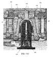
- FIG. 11A shows a release button 640 of the second exemplary embodiment.
- the release button 640 includes a protrusion 641 and cam surfaces 647 that contact and push corresponding cam surfaces 446 of the lock plates 420.
- FIG. 11C shows the protrusion 641 approaching the lock plates 420
- FIG. 11D shows the lock after the lock plates 420 have been pushed, allowing the sliding member 321 to slide freely.
- the release button 640 includes a contact portion 650 that is pushed by a user to release the lock plates 420.
- a slot 643 is provided within the protrusion for engaging at least one rib 644 extending from the upper bearing support 415, and as in the first exemplary embodiment, a release biasing member 642 biases the release button 640 to a position in which the protrusion 641 does not contact the lock plates 420.
- the release biasing member 642 is provided on a support 670 and is secured between a lower one of the ribs 644 and the support 670.
- the protrusion 641 of the release button 640 also includes extensions 660, which slide on a surface of the upper bearing support 615 to stabilize the release button 640.
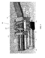
- FIGS. 12A and 12B show features for adjustment of the shoe assembly with respect to the second exemplary embodiment.
- increments are indicated on the sliding member 321. These increments correspond to a distance between a fixed shoe 500 and the movable shoe 300.
- the increment indicated in FIG. 12A is 1 inch and the outside diameter of a pipe P shown in FIG. 12B is also 1 inch.
- FIG. 12A by aligning the increment on the sliding member 321 with a rib 700 on the saw's housing, a user can readily determine the distance between the fixed shoe 500 and the movable shoe 300.
- the distance between the fixed shoe 500 and the movable shoe 300 is adjusted by releasing the sliding member 321 and changing the position of the movable shoe 300.
- FIG. 12B shows the shoes 300, 500 of the saw secured around the pipe P.
Landscapes
- Engineering & Computer Science (AREA)
- Mechanical Engineering (AREA)
- Sawing (AREA)
Applications Claiming Priority (1)
| Application Number | Priority Date | Filing Date | Title |
|---|---|---|---|
| US13/198,881 US8438741B2 (en) | 2011-08-05 | 2011-08-05 | Lock for power tool |
Publications (2)
| Publication Number | Publication Date |
|---|---|
| EP2554313A1 true EP2554313A1 (de) | 2013-02-06 |
| EP2554313B1 EP2554313B1 (de) | 2014-06-18 |
Family
ID=46634053
Family Applications (1)
| Application Number | Title | Priority Date | Filing Date |
|---|---|---|---|
| EP12179282.4A Active EP2554313B1 (de) | 2011-08-05 | 2012-08-03 | Sperre für elektrisches Werkzeug |
Country Status (2)
| Country | Link |
|---|---|
| US (2) | US8438741B2 (de) |
| EP (1) | EP2554313B1 (de) |
Families Citing this family (1)
| Publication number | Priority date | Publication date | Assignee | Title |
|---|---|---|---|---|
| US8733194B2 (en) * | 2011-04-27 | 2014-05-27 | Gm Global Technology Operations, Llc | Dual clutch multi-speed transmission |
Citations (5)
| Publication number | Priority date | Publication date | Assignee | Title |
|---|---|---|---|---|
| US969A (en) | 1838-10-08 | Improvement in the machine for planting all kinds of seeds | ||
| DE19925746A1 (de) * | 1999-06-05 | 2000-12-07 | Bosch Gmbh Robert | Handgeführte Laubsägemaschine |
| US20030206779A1 (en) * | 2000-07-11 | 2003-11-06 | Kopras Robert K. | Automatic locking depth guide for cutting tools and the like |
| US6671969B2 (en) | 2001-12-18 | 2004-01-06 | Porter-Cable/Delta | Adjustable shoe for a reciprocating saw |
| JP2005046970A (ja) * | 2003-07-30 | 2005-02-24 | Makita Corp | 切断工具 |
Family Cites Families (16)
| Publication number | Priority date | Publication date | Assignee | Title |
|---|---|---|---|---|
| US836303A (en) * | 1906-04-26 | 1906-11-20 | Carl V J Christensen | Automatic-locking collar. |
| US3496972A (en) * | 1967-11-02 | 1970-02-24 | Singer Co | Reciprocating power saws with reversible shoe and special blade clamp |
| US5154398A (en) | 1991-11-14 | 1992-10-13 | Mayfield Lenval M | Spring stretcher |
| US5421091A (en) * | 1994-02-23 | 1995-06-06 | S-B Power Tool Company | Adjustable guide shoe for reciprocating saw |
| US5593147A (en) | 1995-09-25 | 1997-01-14 | Read; Kenric W. | Free-standing two-way bar clamp |
| DE29603811U1 (de) * | 1996-03-01 | 1996-04-18 | Drake, Johannes, 33106 Paderborn | Spannzwinge zur Einhandbedienung |
| US6386530B1 (en) * | 2000-08-10 | 2002-05-14 | Worktools, Inc. | Quick action clamp |
| CN2441607Y (zh) * | 2000-08-21 | 2001-08-08 | 仇建平 | 快速定位夹 |
| US6382608B1 (en) | 2000-10-31 | 2002-05-07 | Steven W. Michell | Adjustable clamping and spreading bar clamp or bench vice |
| US7255108B1 (en) * | 2001-08-03 | 2007-08-14 | Patricia Ann Loughlin | Apparatus for inhibiting or preventing the clenching action of the jaw |
| EP1534470A2 (de) | 2002-07-09 | 2005-06-01 | Irwin Industrial Tool Company | Spannzwinge mit seitenaktiviertem bremshebel |
| US6648315B1 (en) | 2002-11-14 | 2003-11-18 | Yung Jen Lee | Clamping device having indirect driving mechanism |
| EP1704021B1 (de) * | 2003-12-12 | 2011-04-20 | Irwin Industrial Tools GmbH | Spann- und/oder spreizwerkzeug mit einem antrieb zum kontinuierlichen verlagern der beiden spannbacken relativ zueinander |
| US7086631B2 (en) * | 2004-03-03 | 2006-08-08 | Eml Technologies Llc | Quick-release telescoping tripod |
| DE102004024862A1 (de) * | 2004-05-19 | 2006-01-05 | Irwin Industrial Tools Gmbh | Spann- und/oder Spreizwerkzeug |
| US6896248B1 (en) * | 2004-07-28 | 2005-05-24 | Beckett Air Incorporated | Clamping device |
-
2011
- 2011-08-05 US US13/198,881 patent/US8438741B2/en active Active
-
2012
- 2012-08-03 EP EP12179282.4A patent/EP2554313B1/de active Active
-
2013
- 2013-03-18 US US13/846,569 patent/US8893393B2/en active Active
Patent Citations (5)
| Publication number | Priority date | Publication date | Assignee | Title |
|---|---|---|---|---|
| US969A (en) | 1838-10-08 | Improvement in the machine for planting all kinds of seeds | ||
| DE19925746A1 (de) * | 1999-06-05 | 2000-12-07 | Bosch Gmbh Robert | Handgeführte Laubsägemaschine |
| US20030206779A1 (en) * | 2000-07-11 | 2003-11-06 | Kopras Robert K. | Automatic locking depth guide for cutting tools and the like |
| US6671969B2 (en) | 2001-12-18 | 2004-01-06 | Porter-Cable/Delta | Adjustable shoe for a reciprocating saw |
| JP2005046970A (ja) * | 2003-07-30 | 2005-02-24 | Makita Corp | 切断工具 |
Also Published As
| Publication number | Publication date |
|---|---|
| US20130212888A1 (en) | 2013-08-22 |
| US8893393B2 (en) | 2014-11-25 |
| US20130031792A1 (en) | 2013-02-07 |
| US8438741B2 (en) | 2013-05-14 |
| EP2554313B1 (de) | 2014-06-18 |
Similar Documents
| Publication | Publication Date | Title |
|---|---|---|
| AU2003262485B2 (en) | Toolless blade holder for a reciprocating tool | |
| EP2368659B1 (de) | Schwenkklingenhaltevorrichtung | |
| EP3028798B1 (de) | Angetriebenes sägewerkzeug mit drehbarer fussplattenanordnug | |
| EP2650088B1 (de) | Drahtführung für ein automatisches Klammergerät | |
| EP2641685B1 (de) | Säbelsägen-Blattklammer | |
| EP2452781B1 (de) | Klammergerätdrahtführung | |
| US9038278B2 (en) | Cutting tools | |
| US7526867B2 (en) | Tool with clamping apparatus and an improved scrolling mechanism | |
| EP2433754A1 (de) | Elektrowerkzeug | |
| US10014127B2 (en) | Safety lock mechanism for trigger switch handle of miter saw | |
| EP2554313B1 (de) | Sperre für elektrisches Werkzeug | |
| US20050283984A1 (en) | Shoe assembly for power tool power tool incorporating such assembly | |
| EP1905541B1 (de) | Spann- und Lösevorrichtung für eine Bandschleifmaschine | |
| US20050246901A1 (en) | Reciprocating power tool | |
| EP1514626B1 (de) | Fussplattenvorrichtung für ein Kraftwerkzeug und ein Kraftwerkzeug mit einer solchen Vorrichtung | |
| US6463838B2 (en) | Bank cutter positioning device | |
| CN110039353B (zh) | 自动换刀机构的换刀臂 | |
| CN212887706U (zh) | 切割工具手柄以及切割工具 | |
| WO2022179452A1 (en) | Powered ratchet | |
| JP2022086851A (ja) | ロックユニット及び電動自転車 |
Legal Events
| Date | Code | Title | Description |
|---|---|---|---|
| PUAI | Public reference made under article 153(3) epc to a published international application that has entered the european phase |
Free format text: ORIGINAL CODE: 0009012 |
|
| AK | Designated contracting states |
Kind code of ref document: A1 Designated state(s): AL AT BE BG CH CY CZ DE DK EE ES FI FR GB GR HR HU IE IS IT LI LT LU LV MC MK MT NL NO PL PT RO RS SE SI SK SM TR |
|
| AX | Request for extension of the european patent |
Extension state: BA ME |
|
| RIN1 | Information on inventor provided before grant (corrected) |
Inventor name: KUEHNE, BRENT A. Inventor name: MILLER, MARK D. Inventor name: VANTRAN, JOHN S |
|
| 17P | Request for examination filed |
Effective date: 20130723 |
|
| RBV | Designated contracting states (corrected) |
Designated state(s): AL AT BE BG CH CY CZ DE DK EE ES FI FR GB GR HR HU IE IS IT LI LT LU LV MC MK MT NL NO PL PT RO RS SE SI SK SM TR |
|
| GRAP | Despatch of communication of intention to grant a patent |
Free format text: ORIGINAL CODE: EPIDOSNIGR1 |
|
| INTG | Intention to grant announced |
Effective date: 20140110 |
|
| GRAS | Grant fee paid |
Free format text: ORIGINAL CODE: EPIDOSNIGR3 |
|
| GRAA | (expected) grant |
Free format text: ORIGINAL CODE: 0009210 |
|
| AK | Designated contracting states |
Kind code of ref document: B1 Designated state(s): AL AT BE BG CH CY CZ DE DK EE ES FI FR GB GR HR HU IE IS IT LI LT LU LV MC MK MT NL NO PL PT RO RS SE SI SK SM TR |
|
| REG | Reference to a national code |
Ref country code: GB Ref legal event code: FG4D |
|
| REG | Reference to a national code |
Ref country code: CH Ref legal event code: EP |
|
| REG | Reference to a national code |
Ref country code: AT Ref legal event code: REF Ref document number: 673048 Country of ref document: AT Kind code of ref document: T Effective date: 20140715 |
|
| REG | Reference to a national code |
Ref country code: IE Ref legal event code: FG4D |
|
| REG | Reference to a national code |
Ref country code: DE Ref legal event code: R096 Ref document number: 602012002127 Country of ref document: DE Effective date: 20140731 |
|
| PG25 | Lapsed in a contracting state [announced via postgrant information from national office to epo] |
Ref country code: CY Free format text: LAPSE BECAUSE OF FAILURE TO SUBMIT A TRANSLATION OF THE DESCRIPTION OR TO PAY THE FEE WITHIN THE PRESCRIBED TIME-LIMIT Effective date: 20140618 Ref country code: NO Free format text: LAPSE BECAUSE OF FAILURE TO SUBMIT A TRANSLATION OF THE DESCRIPTION OR TO PAY THE FEE WITHIN THE PRESCRIBED TIME-LIMIT Effective date: 20140918 Ref country code: FI Free format text: LAPSE BECAUSE OF FAILURE TO SUBMIT A TRANSLATION OF THE DESCRIPTION OR TO PAY THE FEE WITHIN THE PRESCRIBED TIME-LIMIT Effective date: 20140618 Ref country code: GR Free format text: LAPSE BECAUSE OF FAILURE TO SUBMIT A TRANSLATION OF THE DESCRIPTION OR TO PAY THE FEE WITHIN THE PRESCRIBED TIME-LIMIT Effective date: 20140919 Ref country code: LT Free format text: LAPSE BECAUSE OF FAILURE TO SUBMIT A TRANSLATION OF THE DESCRIPTION OR TO PAY THE FEE WITHIN THE PRESCRIBED TIME-LIMIT Effective date: 20140618 |
|
| REG | Reference to a national code |
Ref country code: NL Ref legal event code: VDEP Effective date: 20140618 |
|
| REG | Reference to a national code |
Ref country code: AT Ref legal event code: MK05 Ref document number: 673048 Country of ref document: AT Kind code of ref document: T Effective date: 20140618 |
|
| REG | Reference to a national code |
Ref country code: LT Ref legal event code: MG4D |
|
| PG25 | Lapsed in a contracting state [announced via postgrant information from national office to epo] |
Ref country code: LV Free format text: LAPSE BECAUSE OF FAILURE TO SUBMIT A TRANSLATION OF THE DESCRIPTION OR TO PAY THE FEE WITHIN THE PRESCRIBED TIME-LIMIT Effective date: 20140618 Ref country code: RS Free format text: LAPSE BECAUSE OF FAILURE TO SUBMIT A TRANSLATION OF THE DESCRIPTION OR TO PAY THE FEE WITHIN THE PRESCRIBED TIME-LIMIT Effective date: 20140618 Ref country code: HR Free format text: LAPSE BECAUSE OF FAILURE TO SUBMIT A TRANSLATION OF THE DESCRIPTION OR TO PAY THE FEE WITHIN THE PRESCRIBED TIME-LIMIT Effective date: 20140618 Ref country code: SE Free format text: LAPSE BECAUSE OF FAILURE TO SUBMIT A TRANSLATION OF THE DESCRIPTION OR TO PAY THE FEE WITHIN THE PRESCRIBED TIME-LIMIT Effective date: 20140618 |
|
| PG25 | Lapsed in a contracting state [announced via postgrant information from national office to epo] |
Ref country code: ES Free format text: LAPSE BECAUSE OF FAILURE TO SUBMIT A TRANSLATION OF THE DESCRIPTION OR TO PAY THE FEE WITHIN THE PRESCRIBED TIME-LIMIT Effective date: 20140618 Ref country code: PT Free format text: LAPSE BECAUSE OF FAILURE TO SUBMIT A TRANSLATION OF THE DESCRIPTION OR TO PAY THE FEE WITHIN THE PRESCRIBED TIME-LIMIT Effective date: 20141020 Ref country code: CZ Free format text: LAPSE BECAUSE OF FAILURE TO SUBMIT A TRANSLATION OF THE DESCRIPTION OR TO PAY THE FEE WITHIN THE PRESCRIBED TIME-LIMIT Effective date: 20140618 Ref country code: RO Free format text: LAPSE BECAUSE OF FAILURE TO SUBMIT A TRANSLATION OF THE DESCRIPTION OR TO PAY THE FEE WITHIN THE PRESCRIBED TIME-LIMIT Effective date: 20140618 Ref country code: EE Free format text: LAPSE BECAUSE OF FAILURE TO SUBMIT A TRANSLATION OF THE DESCRIPTION OR TO PAY THE FEE WITHIN THE PRESCRIBED TIME-LIMIT Effective date: 20140618 Ref country code: SK Free format text: LAPSE BECAUSE OF FAILURE TO SUBMIT A TRANSLATION OF THE DESCRIPTION OR TO PAY THE FEE WITHIN THE PRESCRIBED TIME-LIMIT Effective date: 20140618 |
|
| PG25 | Lapsed in a contracting state [announced via postgrant information from national office to epo] |
Ref country code: IS Free format text: LAPSE BECAUSE OF FAILURE TO SUBMIT A TRANSLATION OF THE DESCRIPTION OR TO PAY THE FEE WITHIN THE PRESCRIBED TIME-LIMIT Effective date: 20141018 Ref country code: PL Free format text: LAPSE BECAUSE OF FAILURE TO SUBMIT A TRANSLATION OF THE DESCRIPTION OR TO PAY THE FEE WITHIN THE PRESCRIBED TIME-LIMIT Effective date: 20140618 Ref country code: AT Free format text: LAPSE BECAUSE OF FAILURE TO SUBMIT A TRANSLATION OF THE DESCRIPTION OR TO PAY THE FEE WITHIN THE PRESCRIBED TIME-LIMIT Effective date: 20140618 Ref country code: NL Free format text: LAPSE BECAUSE OF FAILURE TO SUBMIT A TRANSLATION OF THE DESCRIPTION OR TO PAY THE FEE WITHIN THE PRESCRIBED TIME-LIMIT Effective date: 20140618 |
|
| REG | Reference to a national code |
Ref country code: DE Ref legal event code: R097 Ref document number: 602012002127 Country of ref document: DE |
|
| PG25 | Lapsed in a contracting state [announced via postgrant information from national office to epo] |
Ref country code: LU Free format text: LAPSE BECAUSE OF FAILURE TO SUBMIT A TRANSLATION OF THE DESCRIPTION OR TO PAY THE FEE WITHIN THE PRESCRIBED TIME-LIMIT Effective date: 20140803 Ref country code: MC Free format text: LAPSE BECAUSE OF FAILURE TO SUBMIT A TRANSLATION OF THE DESCRIPTION OR TO PAY THE FEE WITHIN THE PRESCRIBED TIME-LIMIT Effective date: 20140618 |
|
| PLBE | No opposition filed within time limit |
Free format text: ORIGINAL CODE: 0009261 |
|
| STAA | Information on the status of an ep patent application or granted ep patent |
Free format text: STATUS: NO OPPOSITION FILED WITHIN TIME LIMIT |
|
| PG25 | Lapsed in a contracting state [announced via postgrant information from national office to epo] |
Ref country code: DK Free format text: LAPSE BECAUSE OF FAILURE TO SUBMIT A TRANSLATION OF THE DESCRIPTION OR TO PAY THE FEE WITHIN THE PRESCRIBED TIME-LIMIT Effective date: 20140618 Ref country code: BE Free format text: LAPSE BECAUSE OF NON-PAYMENT OF DUE FEES Effective date: 20140831 Ref country code: IT Free format text: LAPSE BECAUSE OF FAILURE TO SUBMIT A TRANSLATION OF THE DESCRIPTION OR TO PAY THE FEE WITHIN THE PRESCRIBED TIME-LIMIT Effective date: 20140618 |
|
| REG | Reference to a national code |
Ref country code: IE Ref legal event code: MM4A |
|
| 26N | No opposition filed |
Effective date: 20150319 |
|
| REG | Reference to a national code |
Ref country code: FR Ref legal event code: ST Effective date: 20150430 |
|
| PG25 | Lapsed in a contracting state [announced via postgrant information from national office to epo] |
Ref country code: BE Free format text: LAPSE BECAUSE OF FAILURE TO SUBMIT A TRANSLATION OF THE DESCRIPTION OR TO PAY THE FEE WITHIN THE PRESCRIBED TIME-LIMIT Effective date: 20140618 |
|
| PG25 | Lapsed in a contracting state [announced via postgrant information from national office to epo] |
Ref country code: SI Free format text: LAPSE BECAUSE OF FAILURE TO SUBMIT A TRANSLATION OF THE DESCRIPTION OR TO PAY THE FEE WITHIN THE PRESCRIBED TIME-LIMIT Effective date: 20140618 |
|
| PG25 | Lapsed in a contracting state [announced via postgrant information from national office to epo] |
Ref country code: FR Free format text: LAPSE BECAUSE OF NON-PAYMENT OF DUE FEES Effective date: 20140901 Ref country code: IE Free format text: LAPSE BECAUSE OF NON-PAYMENT OF DUE FEES Effective date: 20140803 |
|
| REG | Reference to a national code |
Ref country code: CH Ref legal event code: PL |
|
| PG25 | Lapsed in a contracting state [announced via postgrant information from national office to epo] |
Ref country code: LI Free format text: LAPSE BECAUSE OF NON-PAYMENT OF DUE FEES Effective date: 20150831 Ref country code: CH Free format text: LAPSE BECAUSE OF NON-PAYMENT OF DUE FEES Effective date: 20150831 |
|
| PG25 | Lapsed in a contracting state [announced via postgrant information from national office to epo] |
Ref country code: SM Free format text: LAPSE BECAUSE OF FAILURE TO SUBMIT A TRANSLATION OF THE DESCRIPTION OR TO PAY THE FEE WITHIN THE PRESCRIBED TIME-LIMIT Effective date: 20140618 |
|
| PG25 | Lapsed in a contracting state [announced via postgrant information from national office to epo] |
Ref country code: MT Free format text: LAPSE BECAUSE OF FAILURE TO SUBMIT A TRANSLATION OF THE DESCRIPTION OR TO PAY THE FEE WITHIN THE PRESCRIBED TIME-LIMIT Effective date: 20140618 Ref country code: BG Free format text: LAPSE BECAUSE OF FAILURE TO SUBMIT A TRANSLATION OF THE DESCRIPTION OR TO PAY THE FEE WITHIN THE PRESCRIBED TIME-LIMIT Effective date: 20140618 |
|
| PG25 | Lapsed in a contracting state [announced via postgrant information from national office to epo] |
Ref country code: HU Free format text: LAPSE BECAUSE OF FAILURE TO SUBMIT A TRANSLATION OF THE DESCRIPTION OR TO PAY THE FEE WITHIN THE PRESCRIBED TIME-LIMIT; INVALID AB INITIO Effective date: 20120803 Ref country code: TR Free format text: LAPSE BECAUSE OF FAILURE TO SUBMIT A TRANSLATION OF THE DESCRIPTION OR TO PAY THE FEE WITHIN THE PRESCRIBED TIME-LIMIT Effective date: 20140618 |
|
| PG25 | Lapsed in a contracting state [announced via postgrant information from national office to epo] |
Ref country code: MK Free format text: LAPSE BECAUSE OF FAILURE TO SUBMIT A TRANSLATION OF THE DESCRIPTION OR TO PAY THE FEE WITHIN THE PRESCRIBED TIME-LIMIT Effective date: 20140618 |
|
| PG25 | Lapsed in a contracting state [announced via postgrant information from national office to epo] |
Ref country code: AL Free format text: LAPSE BECAUSE OF FAILURE TO SUBMIT A TRANSLATION OF THE DESCRIPTION OR TO PAY THE FEE WITHIN THE PRESCRIBED TIME-LIMIT Effective date: 20140618 |
|
| PGFP | Annual fee paid to national office [announced via postgrant information from national office to epo] |
Ref country code: GB Payment date: 20230615 Year of fee payment: 12 |
|
| PGFP | Annual fee paid to national office [announced via postgrant information from national office to epo] |
Ref country code: DE Payment date: 20230607 Year of fee payment: 12 |