EP2554286A1 - Method and apparatus for manufacturing uoe steel pipe - Google Patents
Method and apparatus for manufacturing uoe steel pipe Download PDFInfo
- Publication number
- EP2554286A1 EP2554286A1 EP11759587A EP11759587A EP2554286A1 EP 2554286 A1 EP2554286 A1 EP 2554286A1 EP 11759587 A EP11759587 A EP 11759587A EP 11759587 A EP11759587 A EP 11759587A EP 2554286 A1 EP2554286 A1 EP 2554286A1
- Authority
- EP
- European Patent Office
- Prior art keywords
- bevel
- shape
- pressing
- steel plate
- bevels
- Prior art date
- Legal status (The legal status is an assumption and is not a legal conclusion. Google has not performed a legal analysis and makes no representation as to the accuracy of the status listed.)
- Granted
Links
Images




Classifications
-
- B—PERFORMING OPERATIONS; TRANSPORTING
- B21—MECHANICAL METAL-WORKING WITHOUT ESSENTIALLY REMOVING MATERIAL; PUNCHING METAL
- B21C—MANUFACTURE OF METAL SHEETS, WIRE, RODS, TUBES, PROFILES OR LIKE SEMI-MANUFACTURED PRODUCTS OTHERWISE THAN BY ROLLING; AUXILIARY OPERATIONS USED IN CONNECTION WITH METAL-WORKING WITHOUT ESSENTIALLY REMOVING MATERIAL
- B21C37/00—Manufacture of metal sheets, rods, wire, tubes, profiles or like semi-manufactured products, not otherwise provided for; Manufacture of tubes of special shape
- B21C37/06—Manufacture of metal sheets, rods, wire, tubes, profiles or like semi-manufactured products, not otherwise provided for; Manufacture of tubes of special shape of tubes or metal hoses; Combined procedures for making tubes, e.g. for making multi-wall tubes
- B21C37/08—Making tubes with welded or soldered seams
- B21C37/0826—Preparing the edges of the metal sheet with the aim of having some effect on the weld
-
- B—PERFORMING OPERATIONS; TRANSPORTING
- B23—MACHINE TOOLS; METAL-WORKING NOT OTHERWISE PROVIDED FOR
- B23K—SOLDERING OR UNSOLDERING; WELDING; CLADDING OR PLATING BY SOLDERING OR WELDING; CUTTING BY APPLYING HEAT LOCALLY, e.g. FLAME CUTTING; WORKING BY LASER BEAM
- B23K26/00—Working by laser beam, e.g. welding, cutting or boring
- B23K26/20—Bonding
- B23K26/21—Bonding by welding
- B23K26/24—Seam welding
- B23K26/28—Seam welding of curved planar seams
- B23K26/282—Seam welding of curved planar seams of tube sections
-
- B—PERFORMING OPERATIONS; TRANSPORTING
- B21—MECHANICAL METAL-WORKING WITHOUT ESSENTIALLY REMOVING MATERIAL; PUNCHING METAL
- B21C—MANUFACTURE OF METAL SHEETS, WIRE, RODS, TUBES, PROFILES OR LIKE SEMI-MANUFACTURED PRODUCTS OTHERWISE THAN BY ROLLING; AUXILIARY OPERATIONS USED IN CONNECTION WITH METAL-WORKING WITHOUT ESSENTIALLY REMOVING MATERIAL
- B21C51/00—Measuring, gauging, indicating, counting, or marking devices specially adapted for use in the production or manipulation of material in accordance with subclasses B21B - B21F
-
- B—PERFORMING OPERATIONS; TRANSPORTING
- B23—MACHINE TOOLS; METAL-WORKING NOT OTHERWISE PROVIDED FOR
- B23K—SOLDERING OR UNSOLDERING; WELDING; CLADDING OR PLATING BY SOLDERING OR WELDING; CUTTING BY APPLYING HEAT LOCALLY, e.g. FLAME CUTTING; WORKING BY LASER BEAM
- B23K31/00—Processes relevant to this subclass, specially adapted for particular articles or purposes, but not covered by any single one of main groups B23K1/00 - B23K28/00
- B23K31/02—Processes relevant to this subclass, specially adapted for particular articles or purposes, but not covered by any single one of main groups B23K1/00 - B23K28/00 relating to soldering or welding
- B23K31/027—Making tubes by soldering or welding
-
- B—PERFORMING OPERATIONS; TRANSPORTING
- B23—MACHINE TOOLS; METAL-WORKING NOT OTHERWISE PROVIDED FOR
- B23K—SOLDERING OR UNSOLDERING; WELDING; CLADDING OR PLATING BY SOLDERING OR WELDING; CUTTING BY APPLYING HEAT LOCALLY, e.g. FLAME CUTTING; WORKING BY LASER BEAM
- B23K33/00—Specially-profiled edge portions of workpieces for making soldering or welding connections; Filling the seams formed thereby
- B23K33/004—Filling of continuous seams
- B23K33/006—Filling of continuous seams for cylindrical workpieces
-
- G—PHYSICS
- G01—MEASURING; TESTING
- G01B—MEASURING LENGTH, THICKNESS OR SIMILAR LINEAR DIMENSIONS; MEASURING ANGLES; MEASURING AREAS; MEASURING IRREGULARITIES OF SURFACES OR CONTOURS
- G01B11/00—Measuring arrangements characterised by the use of optical techniques
- G01B11/24—Measuring arrangements characterised by the use of optical techniques for measuring contours or curvatures
- G01B11/245—Measuring arrangements characterised by the use of optical techniques for measuring contours or curvatures using a plurality of fixed, simultaneously operating transducers
-
- G—PHYSICS
- G01—MEASURING; TESTING
- G01B—MEASURING LENGTH, THICKNESS OR SIMILAR LINEAR DIMENSIONS; MEASURING ANGLES; MEASURING AREAS; MEASURING IRREGULARITIES OF SURFACES OR CONTOURS
- G01B11/00—Measuring arrangements characterised by the use of optical techniques
- G01B11/24—Measuring arrangements characterised by the use of optical techniques for measuring contours or curvatures
- G01B11/25—Measuring arrangements characterised by the use of optical techniques for measuring contours or curvatures by projecting a pattern, e.g. one or more lines, moiré fringes on the object
- G01B11/2518—Projection by scanning of the object
- G01B11/2522—Projection by scanning of the object the position of the object changing and being recorded
-
- B—PERFORMING OPERATIONS; TRANSPORTING
- B23—MACHINE TOOLS; METAL-WORKING NOT OTHERWISE PROVIDED FOR
- B23K—SOLDERING OR UNSOLDERING; WELDING; CLADDING OR PLATING BY SOLDERING OR WELDING; CUTTING BY APPLYING HEAT LOCALLY, e.g. FLAME CUTTING; WORKING BY LASER BEAM
- B23K2101/00—Articles made by soldering, welding or cutting
- B23K2101/04—Tubular or hollow articles
- B23K2101/10—Pipe-lines
-
- B—PERFORMING OPERATIONS; TRANSPORTING
- B23—MACHINE TOOLS; METAL-WORKING NOT OTHERWISE PROVIDED FOR
- B23K—SOLDERING OR UNSOLDERING; WELDING; CLADDING OR PLATING BY SOLDERING OR WELDING; CUTTING BY APPLYING HEAT LOCALLY, e.g. FLAME CUTTING; WORKING BY LASER BEAM
- B23K2103/00—Materials to be soldered, welded or cut
- B23K2103/02—Iron or ferrous alloys
- B23K2103/04—Steel or steel alloys
-
- Y—GENERAL TAGGING OF NEW TECHNOLOGICAL DEVELOPMENTS; GENERAL TAGGING OF CROSS-SECTIONAL TECHNOLOGIES SPANNING OVER SEVERAL SECTIONS OF THE IPC; TECHNICAL SUBJECTS COVERED BY FORMER USPC CROSS-REFERENCE ART COLLECTIONS [XRACs] AND DIGESTS
- Y10—TECHNICAL SUBJECTS COVERED BY FORMER USPC
- Y10T—TECHNICAL SUBJECTS COVERED BY FORMER US CLASSIFICATION
- Y10T29/00—Metal working
- Y10T29/49—Method of mechanical manufacture
- Y10T29/49826—Assembling or joining
Definitions
- the present invention relates to a manufacturing method and manufacturing apparatus for a UOE steel pipe or tube (hereinafter referred to as "pipe” when deemed appropriate). To be specific, it relates to a method and apparatus for manufacturing a UOE steel pipe while suppressing manufacturing man-hours and a deterioration of yield by, for example, accurately measuring the cross-sectional shape of a bevel that is formed in an edge part of a thick plate which is a blank steel plate.
- a cutting machine is first used to bevel an edge part of a steel plate, which is the starting material, in preparation for welding.
- beveling is carried out for forming a bevel for welding by a cutting machine called an edge planer with a cemented carbide bite to cut out an edge part of a thick plate (a plate thickness of 6 to 50 mm) in accordance with its outer diameter.
- the beveled steel plate is successively subjected to C-pressing, U-pressing, and O-pressing into an open-pipe having an O-shape cross section. Thereafter, the edge parts of the open pipe, which have beveled, are butted together and welded, and thereafter an expansion processing is carried out to form a UOE steel pipe.
- Patent Literature 1 JP2005-288471A discloses a method for manufacturing a UOE steel pipe.
- the present invention is a method for manufacturing a UOE steel pipe or tube in which a steel plate provided with a bevel in an edge part thereof is successively subjected to C-pressing, U-pressing, and O-pressing into an open pipe or tube, and bevels of the open pipe or tube are butted together and welded, wherein a shape of the bevel of the steel plate is measured prior to the C-pressing and determination is made based on the measurement result whether there is a need for modifying the shape of the bevel of the steel plate before the C-pressing is started.
- the present invention is an apparatus for manufacturing a UOE steel pipe or tube including: a beveling device for forming a bevel in an edge part of a steel plate; a conveyance system for conveying the beveled steel plate; a steel pipe or tube forming device including a C-press machine, a U-press machine, and an O-press machine, and for shaping the beveled steel plate into an open pipe or tube; and a welding machine for butting the bevels of the open pipe or tube and welding the same, wherein the apparatus further includes a bevel-shape measurement device for measuring the shape of the bevel of the steel plate prior to C-pressing carried out by the C-press machine, between the beveling device and the C-press machine, and the bevel-shape measurement device determines whether there is a need for modifying the shape of the bevel of the steel plate before the C-pressing is started based on the measurement result of the shape of the bevel.
- the shape of the above described bevel is measured by a light-section method that irradiates the edge part of the above described steel plate with a linear laser beam that expands in the thickness direction of the above described steel plate.
- a plurality of the above described linear laser beams are applied in the conveyance direction of the above described steel plate.
- the above described steel plate is conveyed with a conveyor roller up to the C-press machine which applies C-press, and the shape of the above described bevel is measured in the vicinity of the conveyor roller and at an exit side of the conveyance direction of the above described steel plate.
- the present invention it is possible to accurately measure the cross-sectional shape of the bevel formed in the edge part of the blank steel plate, for example, a thick plate etc. before C-pressing is started, and specifically it is possible to determine whether or not the shape of the bevel formed in the edge part of the steel plate by a beveling device such as an edge planer is appropriate by using a dedicated bevel-shape measurement device for measuring the bevel shape of the blank steel plate, and quickly output the need for modifying the shape of the bevel to the operator when necessary.
- a beveling device such as an edge planer
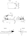
- Figure 1 is an explanatory diagram to schematically show the outline of the present embodiment.
- a manufacturing apparatus 1 relating to the present embodiment includes a beveling device 2, a conveyance system 3, a steel pipe forming device 4, a welding device 5, and a bevel-shape measurement device 6.
- a beveling device 2 As shown in Figure 1 , a manufacturing apparatus 1 relating to the present embodiment includes a beveling device 2, a conveyance system 3, a steel pipe forming device 4, a welding device 5, and a bevel-shape measurement device 6.
- a conveyance system 3 As shown in Figure 1 , a manufacturing apparatus 1 relating to the present embodiment includes a beveling device 2, a conveyance system 3, a steel pipe forming device 4, a welding device 5, and a bevel-shape measurement device 6.
- these components will be successively described.
- the beveling device 2 is a device for forming a bevel in edge parts 7a and 7b of a thick plate (a steel plate having a plate thickness of about 6 to 50 mm) 7 which is the starting material of a large diameter UOE steel pipe 30 having an outer diameter of about 20 to 60 inches.
- a known, ordinary device may be used, which may be exemplified by an edge planer that uses a cemented carbide bite for performing the machining of the edge parts 7a and 7b of the thick plate 7.
- the conveyance system 3 is a device for conveying the thick plate 7, whose edge parts 7a and 7b are provided with bevels 8a and 8b, to the steel pipe forming device 4.
- the conveyance system 3 is made up of a large number of conveyor rollers 9 which are placed side by side in the conveyance direction.
- the thick plate 7 is conveyed by the large number of conveyor rollers 9 making up the conveyance system 3 to a C-press machine 10 where C-pressing is carried out. Since the conveyance system 3 is well known to one skilled in the art, further description on the conveyance system 3 will be omitted.
- the steel pipe forming device 4 is a device including a C-press machine 10, a U-press machine 11, and an O-press machine 12, and for shaping the thick plate 7, which is provided with bevels 8a and 8b, into an open pipe 13.
- the welding device 5 is a device for butting the bevels 8a and 8b of the open pipe 13 together and welding the same. Since the welding device 5 is well known to one skilled in the art, further description on the welding device 5 will be omitted.
- a bevel-shape measurement device 6 is a device disposed between the beveling device 2 and the C-press machine 10 and for measuring the shape of the bevels 8a and 8b of the thick plate 7 before C-pressing by the C-press machine 10 is carried out.
- the bevel-shape measurement device 6 determines whether there is a need for modifying the shape of the bevels 8a and 8b of the thick plate 7 before C-pressing is started for the thick plate 7 by the C-press machine 10.
- the bevel-shape measurement device 6 includes two-dimensional laser range meters 18a and 18b for measuring bevel shapes by a light-section method, and a determination device 61 for determining whether there is a need for modifying the bevel shapes.
- a main feature of the manufacturing apparatus 1 is that the bevel-shape measurement device 6 which has a function of detecting the shapes of the bevels 8a and 8b of the thick plate 7 preferably by a light-section method that irradiates the edge parts 7a and 7b of the thick plate 7 with linear laser beams 16a and 16b, and if there is an abnormality in the shapes of the bevels 8a and 8b, notifying the abnormality to the operator 17 is disposed between the beveling device 2 such as an edge planer, and the C-press machine 10.
- UOE steel pipe 30 is generally manufactured by a device in which the bevel-shape measurement device 6 is omitted from the manufacturing apparatus 1 shown in Figure 1 , it is often the case that the thick plate 7, which is an intermediate product provided with the bevels 8a and 8b, is put on a temporary standby such as between the beveling device 2 (for example, an edge planer) and the C-press machine 10 because of balancing between the respective process capacities.
- the beveling device 2 for example, an edge planer
- the bevel-shape measurement device 6 is newly placed immediately downstream the beveling device 2 such as an edge planer, and a measurement result of the bevel-shape measurement device 6 is fed back to the operator 17 so that the operator 17 can take necessary measures for the bevels 8a and 8b of the thick plate 7 before the C-pressing by the C-press machine 10 is carried out.
- the method for the feedback to the operator 17 may be appropriately chosen, without being particularly limited, in accordance with the configuration of manufacturing process: for example, (1) a method of just notifying the operator by issuing an alarm, (2) a method of temporarily halting the conveyance system 3 in automatic fashion with an alarm, and the like.
- a difference between an appropriate shape of bevels 8a and 8b which is input in advance and the measured shape of bevels 8a and 8b is detected from a measurement result of the shape of the bevels 8a and 8b of the thick plate 7 by the bevel-shape measurement device 6, and if the difference deviates from a reference range, it can be determined that the shape of the bevels 8a and 8b is defective. It is desirable that, by determining that the shape of the bevels 8a and 8b is defective when a plurality of linear laser beams 16a and 16b are applied in the conveyance direction of the thick plate 7 and two or more cases as described above are detected, it may be possible to prevent accidental malfunctions thereby enhancing the reliability of the bevel-shape measurement device 6.
- the measurement of the shape (cross-sectional shape) of the bevels 8a and 8b of the thick plate 7 by the bevel-shape measurement device 6 is carried out by measuring the distance in the width direction of the thick plate between the bevels 8a and 8b of the thick plate 7 and the two-dimensional laser range meters 18a and 18b by using the linear laser beams 16a and 16b. Then, by way of example, a difference from an appropriate cross-sectional shape of the bevels 8a and 8b which is inputted in advance is detected, and when this difference is not less than 5 mm, it is determined that a defective shape has occurred in the bevels 8a and 8b.
- Figure 2 is an explanatory diagram to show an example of the shape of the bevel 8b of the thick plate 7 (the relationship between the angle and the thickness in the plate thickness direction). It is noted that since the bevel 8a is formed in symmetrical with the bevel 8b, Figure 2 will be described by taking the bevel 8b as example.
- angles ( ⁇ 1 to ⁇ 3) of various portions of the bevel 8b, and thicknesses (X1 to X3) in the plate thickness direction having angles ( ⁇ 1 to ⁇ 3) in numeral forms by the bevel-shape measurement device 6.
- the operator 17 can easily adjust the setting of a cemented carbide bite of the beveling device 2 (for example, an edge planer) based on the angles ( ⁇ 1 to ⁇ 3) and the thicknesses (X1 to X3) of the bevel 8b.
- Figure 3 is an explanatory diagram to show a situation where the two-dimensional laser range meters 18a and 18b measure the shape of the bevels 8a and 8b of the thick plate 7.
- a frame 19 is fixedly disposed by being bridged over across the width of the thick plate 7 above the thick plate 7 to be conveyed by the conveyor roller 9.
- the two-dimensional laser range meter 18b is fixedly disposed via a bracket 20 which is fixedly disposed on one end side of the frame 19.
- the two-dimensional laser range meter 18a is disposed movably in the width direction of the thick plate 7 via a bracket 22 which is disposed to be movable in the width direction of the thick plate 7 with respect to the frame 19 by a stepping motor 21.
- This provides the two-dimensional laser range meter 18a that is configured to automatically move to a position suitable for measurement in accordance with the width of the thick plate 7.
- Figure 4A is an explanatory diagram to show a case where the thick plate 7 has a semicylindrical shape
- Figure 4B is an explanatory diagram to show a case where a front edge of the thick plate 7 has a warped shape.
- the two-dimensional laser range meters 18a and 18b which measure the cross-sectional shape of a part irradiated with the linear laser beams 16a and 16 by using a light-section method that irradiates the edge parts 7a and 7b of the thick plate 7 with the linear laser beams 16a and 16b, radiate linear laser beams 16a and 16b divergently as shown in Figures 1 and 3 .
- Figure 5 is an explanatory diagram to show the positional relationship between the conveyor roller and the bevel-shape measurement device 6 (the two-dimensional laser range meters 18a and 18b). Since the thick plate 7 is stably conveyed in the vicinity of the conveyor roller 9, disposing a laser beam radiation port of the two-dimensional laser range meters 18a and 18b near the conveyor roller 9 will make it possible to detect the shape of the bevels 8a and 8b in a stable manner.
- the laser beam radiation port of the two-dimensional laser range meters 18a and 18b is preferably disposed on the downstream side of the conveyor roller 9 in the conveyance direction of the thick plate 7, specifically, at a position of about 500 mm on the downstream side of the conveyor roller 9 in the conveyance direction, because a stable measurement becomes possible. As a result, even when the thick plate 7 is relatively thin, the measurement is less likely to susceptible to a warping of the front edge of the thick plate 7, and accurate measurement can be performed.
- the bevels 8a and 8b have a luster like a mirror surface, if the linear laser beams 16a and 16b are radiated in an arrangement such that a specularly reflected light of the linear laser beams 16a and 16b will be incident into light receiving elements of the two-dimensional laser range meters 18a and 18b, the reflected light will become too strong thereby causing noises and accurate measurement becomes difficult. For this reason, it is preferable to dispose the two-dimensional laser range meters 18a and 18b, for example, 5 to 10° inclined with respect to the conveyance direction of the thick plate 7 from the above described arrangement so that the amount of the reflected light is suppressed by slantedly irradiating the bevel with the linear laser beams 16a and 16b.
- the bevel-shape measurement device 6 measures the shape of the bevels 8a and 8b of the thick plate 7 by using the linear laser beams 16a and 16b which expands in the thickness direction of the thick plate 7. Moreover, it is preferable that the bevel-shape measurement device 6 measures the shape of the bevels 8a and 8b in the vicinity of the conveyor roller 9 and at the exit side in the conveyance direction of the thick plate 7.
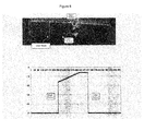
- Figure 6 is a graph to show an example of the measurement result of the shape of the bevel 8b by the bevel-shape measurement device 6. Since the bevel 8b is measured in the thickness direction and the width direction of the thick plate 7 as shown by the graph in Figure 6 , the cross-sectional shape of the entire bevel 8b is accurately measured.
- the bevel-shape measurement device 6 measures the shape of the bevels 8a and 8b at a pitch of about 10 mm in the conveyance direction of the thick plate 7, from the viewpoint of the reliability of measured values.
- each of the two-dimensional laser range meters 18a-1, 18a-2 and 18b-1, 18b-2 measures the shape of the bevels 8a and 8b of the thick plate 7 at the same period of about 20 ms pitch, and shifts the position of the linear laser beam to be radiated by 10 mm respectively between the two-dimensional laser range meter 18a-1 and the two-dimensional laser range meter 18a-2, and between the two-dimensional laser range meter 18b-1 and the two-dimensional laser range meter 18b-2 to perform measurement accurately at a pitch of 10 mm.
- the warping suppressor 23 has a roof-type steel plate 23a whose height decreases from a plate entrance side toward the plate conveyance direction, and it is possible to suppress a warping of, for example, not less than 80 mm which takes place in the thick plate 7 caused by the roof-type steel plate 23a.
- the bevel-shape measurement device 6 can measure the shape of the bevels 8a and 8b of the thick plate 7 at a high accuracy, it has a foreign-substance adherence detection function to detect not only defects in the shape of the bevels 8a and 8b themselves, but also the presence or absence of adherence of foreign substances (for example, machined chips) to the bevels 8a and 8b (in the present invention, adherence of foreign substances is also regarded as a kind of defective shape).
- FIG. 7 is an explanatory diagram to schematically show the procedure of a test for verifying that the bevel-shape measurement device 6 can detect the presence or absence of a foreign substance (for example, machined chips) adhering to the bevels 8a and 8b.
- a foreign substance for example, machined chips
- a machined chip 25 is caused to adhere to various positions of a tentative work 24 which imitates a thick plate, and a linear laser beam 27 is radiated from a two-dimensional laser range meter 26 (trade name LJ-G200 manufactured by KEYENCE CORPORATION) toward the tentative work 24 and the machined chip 25, and the reflection light thereof is detected to measure the shape.
- the shape is also measured without the machined chip 25 being adhered thereto.
- Measurement results are shown in graphs by way of example in Figures 8 to 11 .
- the abscissa in the graphs of Figures 8 to 11 is the distance in the thickness direction of the tentative work 24, and the ordinate is the distance (with a reference distance being 200 mm, measurement is made in a range of ⁇ 40 mm therefrom) between the two-dimensional laser range meter 26 and the tentative work 24 or the machined chip 25.
- Figure 8 shows a case where a machined chip 25 is not adhering to the tentative work 24
- Figure 9 shows a case where a machined chip 25 is adhering to a middle portion of the tentative work
- Figure 10 shows a case where a machined chip 25 is adhering to a position of 10 mm from the upper surface of the tentative work
- Figure 11 shows a case where a machined chip 25 is adhering to a middle portion of the tentative work 24.
- the shape of the bevels 8a and 8b before C-pressing by the C-press machine 10 is carried out is measured as described above by the bevel-shape measurement device 6 on the thick plate 7 in whose edge parts 7a and 7b the bevels 8a and 8b are formed by the beveling device 2.
- the bevel-shape measurement device 6 determines whether there is a need for modifying the shape of the bevels 8a and 8b of the thick plate 7 based on the measurement result as described above before C-pressing by the C-press machine 10 is started.
- the bevel-shape measurement device 6 When determining that there is no need for modifying the shape of the bevels 8a and 8b of the thick plate 7, the bevel-shape measurement device 6 does not output an alarm etc. to the operator 17.
- the thick plate 7 is fed as-is to the steel pipe forming device 4, and is subjected to C-pressing by the C-press machine 10, U-pressing by the U-press machine 11, and O-pressing by the O-press machine 12 to be shaped into an open pipe 13.
- the open pipe 13 is fed to the welding device 5, and the bevels 8a and 8b are butted together and welded to be formed into a steel pipe 14; the steel pipe 14 being fed to an expansion processing device 15 and subjected to expansion processing to be formed into a UOE steel pipe 30.
- the bevel-shape measurement device 6 when determining that there is a need for modifying the shape of the bevels 8a and 8b of the thick plate 7, the bevel-shape measurement device 6 outputs an alarm etc. to the operator 17.
- the operator 17 temporarily stops the beveling device 2 and adjusts the setting of the cemented carbide bite of the beveling device 2 such that appropriate angles ( ⁇ 1 to ⁇ 3) and thicknesses (X1 to X3) are obtained, for example, based on the angles ( ⁇ 1 to ⁇ 3) and the thicknesses (X1 to X3) of the bevels 8a and 8b outputted by the bevel-shape measurement device 6.
- the modification of the shape of the bevels 8a and 8b is performed by the beveling device 2 including the cemented carbide bite of which setting has been adjusted.
- the thick plate 7 for which modification of the shape of the bevels 8a and 8b has been thus performed is fed to the steel pipe forming device 4 and is subjected to C-pressing by the C-press machine 10, U-pressing by the U-press machine 11, and O-pressing by the O-press machine 12 to be shaped into an open pipe 13.
- the open pipe 13 is fed to the welding device 5 so that the bevels 8a and 8b are butted together and welded to form a steel pipe 14, and further the steel pipe 14 is fed to an expansion processing device 15 and subjected to expansion processing to form a UOE steel pipe 30.
- the beveling device 2 such as an edge planer
- a dedicated bevel-shape measurement device 6 for measuring the shape of the bevels 8a and 8b of the thick plate 7; and when it is not appropriate, it is possible to quickly output the need for modifying the shape of the bevels 8a and 8b to the operator 17.
- the UOE steel pipe 30 it becomes possible to manufacture the UOE steel pipe 30 while preventing an increase in man-hours and a decline of yield caused by abnormalities of the shape of the bevels 8a and 8b.
- the present invention since it is also possible to detect the presence or absence of a machined chip during beveling which is thermally stuck to and remains to adhere to the bevels 8a and 8b, it is possible to significantly suppress a defective holding down (a dent flaw) of the outer surface of the UOE steel pipe 30 caused by the press working at the steel pipe forming device 4.
Landscapes
- Engineering & Computer Science (AREA)
- Mechanical Engineering (AREA)
- Physics & Mathematics (AREA)
- General Physics & Mathematics (AREA)
- Optics & Photonics (AREA)
- Computer Vision & Pattern Recognition (AREA)
- Plasma & Fusion (AREA)
- Length Measuring Devices By Optical Means (AREA)
Abstract
Description
- The present invention relates to a manufacturing method and manufacturing apparatus for a UOE steel pipe or tube (hereinafter referred to as "pipe" when deemed appropriate). To be specific, it relates to a method and apparatus for manufacturing a UOE steel pipe while suppressing manufacturing man-hours and a deterioration of yield by, for example, accurately measuring the cross-sectional shape of a bevel that is formed in an edge part of a thick plate which is a blank steel plate.
- In a typical manufacturing process of a UOE steel pipe, a cutting machine is first used to bevel an edge part of a steel plate, which is the starting material, in preparation for welding. In particular, in manufacturing of a large diameter UOE steel pipe having an outer diameter of about 20 to 60 inches, beveling is carried out for forming a bevel for welding by a cutting machine called an edge planer with a cemented carbide bite to cut out an edge part of a thick plate (a plate thickness of 6 to 50 mm) in accordance with its outer diameter.
- The beveled steel plate is successively subjected to C-pressing, U-pressing, and O-pressing into an open-pipe having an O-shape cross section. Thereafter, the edge parts of the open pipe, which have beveled, are butted together and welded, and thereafter an expansion processing is carried out to form a UOE steel pipe.
- For example, Patent Literature 1 (
JP2005-288471A - In a conventional manufacturing process of UOE steel pipe, in order to determine whether or not a normal bevel has been formed by beveling, it is necessary to sample a welding bead of a pipe end surface of the UOE steel pipe after welding, grind the end surface of the sampled welding bead by using a file and a grinding stone, and further estimate the bevel shape from the bead shape after pickling.
- This means that, after the edge parts of the open pipe are welded together, there is no other way to determine whether or not the bevel shape is appropriate than to estimate it based on the fused state between the weld metal and the base metal, and it takes much time until to determine that the bevel shape is not appropriate.
- Further, even if it is assumed that a defect of bevel shape of one manufactured UOE steel pipe can be observed and found after welding, similar inappropriate beveling may have been performed when the defect has been found, on a large number of thick plates, which are the starting material of many other UOE steel pipes that are manufactured following the aforementioned one UOE steel pipe. For this reason, since it becomes necessary to additionally cut the bevels of the large number of thick plates, the production efficiency of UOE steel pipe will be significantly deteriorated.
- In particular, if a thick plate is fed to a C-press machine in the next process with a machined chip attached to the bevel, which has been generated during beveling, the machined chip, if detached from the bevel during C-pressing, falls into the die of the C-press machine and adheres to the die. Thus, a further problem is that the machined chip adhering to the die of the C-press machine causes a dent flaw on the outer surface of the UOE steel pipe, which is made of a thick plate as a starting material that is to be fed to the C-press machine after the above described thick plate.
- These are technical problems that are desired to be solved promptly, because they directly lead to an increase in manufacturing man-hours and a decline of yield of the UOE steel pipe.
- The present invention is a method for manufacturing a UOE steel pipe or tube in which a steel plate provided with a bevel in an edge part thereof is successively subjected to C-pressing, U-pressing, and O-pressing into an open pipe or tube, and bevels of the open pipe or tube are butted together and welded, wherein a shape of the bevel of the steel plate is measured prior to the C-pressing and determination is made based on the measurement result whether there is a need for modifying the shape of the bevel of the steel plate before the C-pressing is started.
- From another aspect, the present invention is an apparatus for manufacturing a UOE steel pipe or tube including: a beveling device for forming a bevel in an edge part of a steel plate; a conveyance system for conveying the beveled steel plate; a steel pipe or tube forming device including a C-press machine, a U-press machine, and an O-press machine, and for shaping the beveled steel plate into an open pipe or tube; and a welding machine for butting the bevels of the open pipe or tube and welding the same, wherein the apparatus further includes a bevel-shape measurement device for measuring the shape of the bevel of the steel plate prior to C-pressing carried out by the C-press machine, between the beveling device and the C-press machine, and the bevel-shape measurement device determines whether there is a need for modifying the shape of the bevel of the steel plate before the C-pressing is started based on the measurement result of the shape of the bevel.
- In these aspects of the present invention, it is preferable that the shape of the above described bevel is measured by a light-section method that irradiates the edge part of the above described steel plate with a linear laser beam that expands in the thickness direction of the above described steel plate.
In these aspects of the present invention, it is preferable that a plurality of the above described linear laser beams are applied in the conveyance direction of the above described steel plate. - Further, in these aspects of the present invention, it is preferable that after the above described bevel is formed, the above described steel plate is conveyed with a conveyor roller up to the C-press machine which applies C-press, and the shape of the above described bevel is measured in the vicinity of the conveyor roller and at an exit side of the conveyance direction of the above described steel plate.
- According to the present invention, it is possible to accurately measure the cross-sectional shape of the bevel formed in the edge part of the blank steel plate, for example, a thick plate etc. before C-pressing is started, and specifically it is possible to determine whether or not the shape of the bevel formed in the edge part of the steel plate by a beveling device such as an edge planer is appropriate by using a dedicated bevel-shape measurement device for measuring the bevel shape of the blank steel plate, and quickly output the need for modifying the shape of the bevel to the operator when necessary. This makes it possible to manufacture a UOE steel pipe or tube while preventing an increase in man-hours and a decline of yield caused by inappropriateness of the shape of the bevel.
-
-
Figure 1 is an explanatory diagram to schematically show the outline of an embodiment of the present invention. -
Figure 2 is an explanatory diagram to show an example of the shape of the bevel of the thick plate. -
Figure 3 is an explanatory diagram to show a situation where the two-dimensional laser range meters measure the shape of the bevels of the thick plate. -
Figure 4A is an explanatory diagram to show a case where the thick plate has a semicylindrical shape, andFigure 4B is an explanatory diagram to show a case where a front edge of the thick plate has a warped shape. -
Figure 5 is an explanatory diagram to show the positional relationship between the conveyor roller and the bevel-shape measurement device. -
Figure 6 is a graph to show an example of the measurement result of the shape of the bevel by the bevel-shape measurement device. -
Figure 7 is an explanatory diagram to schematically show the procedure of a test for verifying that the bevel-shape measurement device can detect the presence or absence of a foreign substance. -
Figure 8 is a graph to show an example of the result of the test shown inFigure 7 . -
Figure 9 is a graph to show an example of the result of the test shown inFigure 7 . -
Figure 10 is a graph to show an example of the result of the test shown inFigure 7 . -
Figure 11 is a graph to show an example of the result of the test shown inFigure 7 . - Hereafter, an embodiment for carrying out the present invention will be described with reference to the appended drawings.
First, the manufacturing apparatus relating to the present embodiment will be described.Figure 1 is an explanatory diagram to schematically show the outline of the present embodiment. - As shown in
Figure 1 , amanufacturing apparatus 1 relating to the present embodiment includes abeveling device 2, aconveyance system 3, a steelpipe forming device 4, awelding device 5, and a bevel-shape measurement device 6. Hereafter, these components will be successively described. - The
beveling device 2 is a device for forming a bevel inedge parts UOE steel pipe 30 having an outer diameter of about 20 to 60 inches. - As the
beveling device 2, a known, ordinary device may be used, which may be exemplified by an edge planer that uses a cemented carbide bite for performing the machining of theedge parts thick plate 7. - Since the
beveling device 2 is well known to one skilled in the art, further description on thebeveling device 2 will be omitted. - The
conveyance system 3 is a device for conveying thethick plate 7, whoseedge parts bevels pipe forming device 4. Theconveyance system 3 is made up of a large number of conveyor rollers 9 which are placed side by side in the conveyance direction. - After the
bevels thick plate 7 is conveyed by the large number of conveyor rollers 9 making up theconveyance system 3 to a C-press machine 10 where C-pressing is carried out.
Since theconveyance system 3 is well known to one skilled in the art, further description on theconveyance system 3 will be omitted. - The steel
pipe forming device 4 is a device including a C-press machine 10, aU-press machine 11, and an O-press machine 12, and for shaping thethick plate 7, which is provided withbevels - Since the steel
pipe forming device 4 is well known to one skilled in the art, further description on the steelpipe forming device 4 will be omitted. - The
welding device 5 is a device for butting thebevels welding device 5 is well known to one skilled in the art, further description on thewelding device 5 will be omitted. - It is noted that the
steel pipe 14 which has been welded by thewelding device 5 is subjected to expansion processing by anexpansion processing device 15 into aUOE steel pipe 30 which is the product. - A bevel-
shape measurement device 6 is a device disposed between thebeveling device 2 and the C-press machine 10 and for measuring the shape of thebevels thick plate 7 before C-pressing by the C-press machine 10 is carried out. - The bevel-
shape measurement device 6 determines whether there is a need for modifying the shape of thebevels thick plate 7 before C-pressing is started for thethick plate 7 by the C-press machine 10. The bevel-shape measurement device 6 includes two-dimensionallaser range meters determination device 61 for determining whether there is a need for modifying the bevel shapes. - A main feature of the
manufacturing apparatus 1 is that the bevel-shape measurement device 6 which has a function of detecting the shapes of thebevels thick plate 7 preferably by a light-section method that irradiates theedge parts thick plate 7 withlinear laser beams bevels operator 17 is disposed between thebeveling device 2 such as an edge planer, and the C-press machine 10. - While a
UOE steel pipe 30 is generally manufactured by a device in which the bevel-shape measurement device 6 is omitted from themanufacturing apparatus 1 shown inFigure 1 , it is often the case that thethick plate 7, which is an intermediate product provided with thebevels press machine 10 because of balancing between the respective process capacities. - In the present embodiment, the bevel-
shape measurement device 6 is newly placed immediately downstream thebeveling device 2 such as an edge planer, and a measurement result of the bevel-shape measurement device 6 is fed back to theoperator 17 so that theoperator 17 can take necessary measures for thebevels thick plate 7 before the C-pressing by the C-press machine 10 is carried out. - The method for the feedback to the
operator 17 may be appropriately chosen, without being particularly limited, in accordance with the configuration of manufacturing process: for example, (1) a method of just notifying the operator by issuing an alarm, (2) a method of temporarily halting theconveyance system 3 in automatic fashion with an alarm, and the like. - A difference between an appropriate shape of
bevels bevels bevels thick plate 7 by the bevel-shape measurement device 6, and if the difference deviates from a reference range, it can be determined that the shape of thebevels bevels linear laser beams thick plate 7 and two or more cases as described above are detected, it may be possible to prevent accidental malfunctions thereby enhancing the reliability of the bevel-shape measurement device 6. - The measurement of the shape (cross-sectional shape) of the
bevels thick plate 7 by the bevel-shape measurement device 6 is carried out by measuring the distance in the width direction of the thick plate between thebevels thick plate 7 and the two-dimensionallaser range meters linear laser beams bevels bevels -
Figure 2 is an explanatory diagram to show an example of the shape of thebevel 8b of the thick plate 7 (the relationship between the angle and the thickness in the plate thickness direction). It is noted that since thebevel 8a is formed in symmetrical with thebevel 8b,Figure 2 will be described by taking thebevel 8b as example. - It is possible to measure angles (θ1 to θ3) of various portions of the
bevel 8b, and thicknesses (X1 to X3) in the plate thickness direction having angles (θ1 to θ3) in numeral forms by the bevel-shape measurement device 6. For this reason, theoperator 17 can easily adjust the setting of a cemented carbide bite of the beveling device 2 (for example, an edge planer) based on the angles (θ1 to θ3) and the thicknesses (X1 to X3) of thebevel 8b. -
Figure 3 is an explanatory diagram to show a situation where the two-dimensionallaser range meters bevels thick plate 7.
Aframe 19 is fixedly disposed by being bridged over across the width of thethick plate 7 above thethick plate 7 to be conveyed by the conveyor roller 9. The two-dimensionallaser range meter 18b is fixedly disposed via abracket 20 which is fixedly disposed on one end side of theframe 19. On one hand, the two-dimensionallaser range meter 18a is disposed movably in the width direction of thethick plate 7 via abracket 22 which is disposed to be movable in the width direction of thethick plate 7 with respect to theframe 19 by a stepping motor 21. This provides the two-dimensionallaser range meter 18a that is configured to automatically move to a position suitable for measurement in accordance with the width of thethick plate 7. -
Figure 4A is an explanatory diagram to show a case where thethick plate 7 has a semicylindrical shape, andFigure 4B is an explanatory diagram to show a case where a front edge of thethick plate 7 has a warped shape.
The two-dimensionallaser range meters linear laser beams edge parts thick plate 7 with thelinear laser beams linear laser beams Figures 1 and3 . As a result, setting a laser detection range L to be not less than a supposed movable range in the vertical direction of the cross section of thethick plate 7 as shown inFigure 4A makes it possible to measure the shape of the entire cross section of thebevels thick plate 7 even in a case where thethick plate 7 has a semicylindrical shape as shown inFigure 4A , and a case where a front edge of thethick plate 7 has a warped shape as shown inFigure 4B . -
Figure 5 is an explanatory diagram to show the positional relationship between the conveyor roller and the bevel-shape measurement device 6 (the two-dimensionallaser range meters
Since thethick plate 7 is stably conveyed in the vicinity of the conveyor roller 9, disposing a laser beam radiation port of the two-dimensionallaser range meters bevels - The laser beam radiation port of the two-dimensional
laser range meters thick plate 7, specifically, at a position of about 500 mm on the downstream side of the conveyor roller 9 in the conveyance direction, because a stable measurement becomes possible. As a result, even when thethick plate 7 is relatively thin, the measurement is less likely to susceptible to a warping of the front edge of thethick plate 7, and accurate measurement can be performed. - Further, since the
bevels linear laser beams linear laser beams laser range meters laser range meters thick plate 7 from the above described arrangement so that the amount of the reflected light is suppressed by slantedly irradiating the bevel with thelinear laser beams - In this way, it is preferable that the bevel-
shape measurement device 6 measures the shape of thebevels thick plate 7 by using thelinear laser beams thick plate 7. Moreover, it is preferable that the bevel-shape measurement device 6 measures the shape of thebevels thick plate 7. -
Figure 6 is a graph to show an example of the measurement result of the shape of thebevel 8b by the bevel-shape measurement device 6. Since thebevel 8b is measured in the thickness direction and the width direction of thethick plate 7 as shown by the graph inFigure 6 , the cross-sectional shape of theentire bevel 8b is accurately measured. - It is preferable to arrange side by side a plurality (two in the example shown in
Figure 5 ) of the two-dimensionallaser range meters shape measurement device 6.
For example, it is preferable that the bevel-shape measurement device 6 measures the shape of thebevels thick plate 7, from the viewpoint of the reliability of measured values. Supposing that the conveyance speed of thethick plate 7 is, for example, 60 m/min, it is preferable that two two-dimensionallaser range meters 18a-1, 18a-2 and 18b-1, 18b-2 (these are not shown) are arranged on one side in the conveyance direction as shown inFigure 5 , and each of the two-dimensionallaser range meters 18a-1, 18a-2 and 18b-1, 18b-2 measures the shape of thebevels thick plate 7 at the same period of about 20 ms pitch, and shifts the position of the linear laser beam to be radiated by 10 mm respectively between the two-dimensionallaser range meter 18a-1 and the two-dimensionallaser range meter 18a-2, and between the two-dimensionallaser range meter 18b-1 and the two-dimensionallaser range meter 18b-2 to perform measurement accurately at a pitch of 10 mm. - It is desirable to provide a
warping suppressor 23 as shown inFigure 5 before the two-dimensionallaser range meters shape measurement device 6. The warpingsuppressor 23 has a roof-type steel plate 23a whose height decreases from a plate entrance side toward the plate conveyance direction, and it is possible to suppress a warping of, for example, not less than 80 mm which takes place in thethick plate 7 caused by the roof-type steel plate 23a. - Further, since the bevel-
shape measurement device 6 can measure the shape of thebevels thick plate 7 at a high accuracy, it has a foreign-substance adherence detection function to detect not only defects in the shape of thebevels bevels - For example, if the shape measured by the bevel-
shape measurement device 6 deviates by 5 mm or more from an appropriate shape, an alarm sounds notifying theoperator 17 of adherence of a foreign substance to thebevels
Figure 7 is an explanatory diagram to schematically show the procedure of a test for verifying that the bevel-shape measurement device 6 can detect the presence or absence of a foreign substance (for example, machined chips) adhering to thebevels - In this test, a machined
chip 25 is caused to adhere to various positions of atentative work 24 which imitates a thick plate, and alinear laser beam 27 is radiated from a two-dimensional laser range meter 26 (trade name LJ-G200 manufactured by KEYENCE CORPORATION) toward thetentative work 24 and the machinedchip 25, and the reflection light thereof is detected to measure the shape. The shape is also measured without the machinedchip 25 being adhered thereto. - Measurement results are shown in graphs by way of example in
Figures 8 to 11 . The abscissa in the graphs ofFigures 8 to 11 is the distance in the thickness direction of thetentative work 24, and the ordinate is the distance (with a reference distance being 200 mm, measurement is made in a range of ±40 mm therefrom) between the two-dimensionallaser range meter 26 and thetentative work 24 or the machinedchip 25. -
Figure 8 shows a case where a machinedchip 25 is not adhering to thetentative work 24,Figure 9 shows a case where a machinedchip 25 is adhering to a middle portion of thetentative work 24,Figure 10 shows a case where a machinedchip 25 is adhering to a position of 10 mm from the upper surface of thetentative work 24, and furtherFigure 11 shows a case where a machinedchip 25 is adhering to a middle portion of thetentative work 24. - Comparing the graph of
Figure 8 with the graphs ofFigures 9 to 11 , there are clear differences between them, thereby showing that the presence or absence of adherence of a foreign substance (for example, a machined chip) to thebevels shape measurement device 6. - Next, the situation of manufacturing a
UOE steel pipe 30 by themanufacturing apparatus 1 relating to the present embodiment will be described.
In the present invention, the shape of thebevels press machine 10 is carried out is measured as described above by the bevel-shape measurement device 6 on thethick plate 7 in whoseedge parts bevels beveling device 2. - Then, the bevel-
shape measurement device 6 determines whether there is a need for modifying the shape of thebevels thick plate 7 based on the measurement result as described above before C-pressing by the C-press machine 10 is started. - When determining that there is no need for modifying the shape of the
bevels thick plate 7, the bevel-shape measurement device 6 does not output an alarm etc. to theoperator 17. In this case, thethick plate 7 is fed as-is to the steelpipe forming device 4, and is subjected to C-pressing by the C-press machine 10, U-pressing by theU-press machine 11, and O-pressing by the O-press machine 12 to be shaped into an open pipe 13. The open pipe 13 is fed to thewelding device 5, and thebevels steel pipe 14; thesteel pipe 14 being fed to anexpansion processing device 15 and subjected to expansion processing to be formed into aUOE steel pipe 30. - On one hand, when determining that there is a need for modifying the shape of the
bevels thick plate 7, the bevel-shape measurement device 6 outputs an alarm etc. to theoperator 17. In this case, theoperator 17 temporarily stops thebeveling device 2 and adjusts the setting of the cemented carbide bite of thebeveling device 2 such that appropriate angles (θ1 to θ3) and thicknesses (X1 to X3) are obtained, for example, based on the angles (θ1 to θ3) and the thicknesses (X1 to X3) of thebevels shape measurement device 6. Then, for all the thick plates which have beveled after the above describedthick plate 7, the modification of the shape of thebevels beveling device 2 including the cemented carbide bite of which setting has been adjusted. - Then, the
thick plate 7 for which modification of the shape of thebevels pipe forming device 4 and is subjected to C-pressing by the C-press machine 10, U-pressing by theU-press machine 11, and O-pressing by the O-press machine 12 to be shaped into an open pipe 13. The open pipe 13 is fed to thewelding device 5 so that thebevels steel pipe 14, and further thesteel pipe 14 is fed to anexpansion processing device 15 and subjected to expansion processing to form aUOE steel pipe 30. - In this way, according to the present invention, it is determined whether or not the shape of the
bevels edge parts thick plate 7 by thebeveling device 2 such as an edge planer is appropriate by using a dedicated bevel-shape measurement device 6 for measuring the shape of thebevels thick plate 7; and when it is not appropriate, it is possible to quickly output the need for modifying the shape of thebevels operator 17. As a result, it becomes possible to manufacture theUOE steel pipe 30 while preventing an increase in man-hours and a decline of yield caused by abnormalities of the shape of thebevels - Moreover, according to the present invention, it becomes possible to very quickly perform the adjustment of the cutting quantity of the cemented carbide bite of the
beveling device 2 such as an edge planer, and to suppress the occurrence of welding defects which have been occurring at the start of the manufacturing of UOE steel pipe so far. - Further, according to the present invention, since it is also possible to detect the presence or absence of a machined chip during beveling which is thermally stuck to and remains to adhere to the
bevels UOE steel pipe 30 caused by the press working at the steelpipe forming device 4. -
- 1
- Apparatus for manufacturing UOE steel pipe
- 2
- Beveling device
- 3
- Conveyance system
- 4
- Steel pipe forming device
- 5
- Welding device
- 6
- Bevel-shape measurement device
- 7
- Thick plate
- 7a, 7b
- Edge part
- 8a, 8b
- Bevel
- 9
- Conveyor roller
- 10
- C-press machine
- 11
- U-press machine
- 12
- O-press machine
- 13
- Open pipe
- 14
- Steel pipe
- 15
- Expansion processing device
- 16a, 16b
- Linear laser beam
- 17
- Operator
- 18a, 18b
- Two-dimensional laser range meter
- 18a-1, 18a-2, 18b-1, 18b-2
- Two-dimensional laser range meter
- 19
- Frame
- 20
- Bracket
- 21
- Stepping motor
- 22
- Bracket
- 23
- Warping suppressor
- 24
- Tentative work
- 25
- Machined chip
- 26
- Two-dimensional laser range meter
- 27
- Linear laser beam
- 30
- UOE steel pipe
Claims (5)
- A method for manufacturing a UOE steel pipe or tube in which a steel plate provided with a bevel in an edge part thereof is successively subjected to C-pressing, U-pressing, and O-pressing into an open pipe or tube, and bevels of the open pipe or tube are butted together and welded, wherein
a shape of the bevel of the steel plate is measured prior to the C-pressing and determination is made based on the measurement result whether there is a need for modifying the shape of the bevel of the steel plate before the C-pressing is started. - The method for manufacturing a UOE steel pipe or tube according to claim 1, wherein
the shape of the bevel is measured by a light-section method that irradiates the edge part of the steel plate with a linear laser beam which expands in the thickness direction of the steel plate. - The method for manufacturing a UOE steel pipe or tube according to claim 1 or 2, wherein
a plurality of the linear laser beams are radiated in the conveyance direction of the steel plate. - The method for manufacturing a UOE steel pipe or tube according to any of claims 1 to 3, wherein
after the bevel is formed, the steel plate is conveyed by a conveyor roller to the C-press machine where the C-pressing is carried out, and the shape of the bevel is measured in the vicinity of the conveyor roller and at an exit side of the conveyance direction of the steel plate. - An apparatus for manufacturing a UOE steel pipe or tube comprising:a beveling device for forming a bevel in an edge part of a steel plate;a conveyance system for conveying the beveled steel plate;a steel pipe or tube forming device including a C-press machine, a U-press machine, and an O-press machine, and for shaping the beveled steel plate into an open pipe or tube; anda welding machine for butting the bevels of the open pipe or tube and welding the same, whereinthe apparatus further comprises a bevel-shape measurement device for measuring the shape of the bevel of the steel plate prior to C-pressing carried out by the C-press machine, between the beveling device and the C-press machine, andthe bevel-shape measurement device determines whether there is a need for modifying the shape of the bevel of the steel plate before the C-pressing is started based on the measurement result of the shape of the bevel.
Applications Claiming Priority (2)
| Application Number | Priority Date | Filing Date | Title |
|---|---|---|---|
| JP2010072627 | 2010-03-26 | ||
| PCT/JP2011/057389 WO2011118783A1 (en) | 2010-03-26 | 2011-03-25 | Method and apparatus for manufacturing uoe steel pipe |
Publications (3)
| Publication Number | Publication Date |
|---|---|
| EP2554286A1 true EP2554286A1 (en) | 2013-02-06 |
| EP2554286A4 EP2554286A4 (en) | 2017-06-14 |
| EP2554286B1 EP2554286B1 (en) | 2019-06-12 |
Family
ID=44673322
Family Applications (1)
| Application Number | Title | Priority Date | Filing Date |
|---|---|---|---|
| EP11759587.6A Active EP2554286B1 (en) | 2010-03-26 | 2011-03-25 | Method and apparatus for manufacturing uoe steel pipe |
Country Status (5)
| Country | Link |
|---|---|
| US (1) | US20130256275A1 (en) |
| EP (1) | EP2554286B1 (en) |
| JP (1) | JP4883429B2 (en) |
| CN (1) | CN102821886B (en) |
| WO (1) | WO2011118783A1 (en) |
Families Citing this family (14)
| Publication number | Priority date | Publication date | Assignee | Title |
|---|---|---|---|---|
| EP2468429A1 (en) * | 2010-12-21 | 2012-06-27 | Siemens VAI Metals Technologies GmbH | Method and device for measuring the speed of a rolled product |
| JP6163342B2 (en) * | 2013-04-02 | 2017-07-12 | 新日鉄住金エンジニアリング株式会社 | Groove shape measuring method and apparatus |
| WO2014188468A1 (en) * | 2013-05-20 | 2014-11-27 | Jfeスチール株式会社 | Bending press device, bending press method, device for producing steel pipe, and method for producing steel pipe |
| JP2016087652A (en) * | 2014-11-05 | 2016-05-23 | Jfeスチール株式会社 | Thick steel plate warpage detection method and device |
| CN105032980B (en) * | 2015-09-09 | 2017-07-11 | 航天海鹰(哈尔滨)钛业有限公司 | A kind of manufacturing process of the complicated variable cross-section tubing of thin-wall titanium alloy and application |
| DE102015218599A1 (en) * | 2015-09-28 | 2017-03-30 | Bayerische Motoren Werke Aktiengesellschaft | Method for directing a distortion of a component by a straightening device and straightening device |
| JP6666112B2 (en) * | 2015-10-27 | 2020-03-13 | ファナック株式会社 | Tool cleaning equipment for machine tools |
| JP5871417B1 (en) * | 2015-12-04 | 2016-03-01 | 中川産業株式会社 | Manufacturing method of double pipe |
| CN105666249A (en) * | 2016-03-07 | 2016-06-15 | 安徽康成工业产品设计有限公司 | Measuring device connected to pipe beveling machine |
| CN107414424B (en) * | 2017-07-26 | 2019-10-15 | 东方电气集团东方锅炉股份有限公司 | A kind of forming method of large diameter thin wall stainless steel cylinder |
| JP6984621B2 (en) * | 2019-01-30 | 2021-12-22 | Jfeスチール株式会社 | Forging press equipment, forging press method and metal material manufacturing method |
| CN114193240B (en) * | 2021-12-16 | 2022-10-04 | 大连理工大学 | Shape following machining process method for weld joint in shell of special mobile robot |
| CN114485403B (en) * | 2022-01-29 | 2024-04-09 | 中石化石油机械股份有限公司沙市钢管分公司 | A submerged arc welded pipe milling groove processing size follow-up measuring device and measuring method |
| JP7800488B2 (en) * | 2023-03-24 | 2026-01-16 | トヨタ自動車株式会社 | Processing system, processing method and program |
Family Cites Families (14)
| Publication number | Priority date | Publication date | Assignee | Title |
|---|---|---|---|---|
| SU654153A3 (en) * | 1973-10-17 | 1979-03-25 | Маннесманн Аг (Фирма) | Device for bending sheet edges |
| US4666303A (en) * | 1983-07-11 | 1987-05-19 | Diffracto Ltd. | Electro-optical gap and flushness sensors |
| JPS61217747A (en) * | 1985-03-23 | 1986-09-27 | Yodogawa Seikosho:Kk | Pinhole detector |
| JPS63104797A (en) * | 1986-10-22 | 1988-05-10 | Nkk Corp | Manufacturing method of welded steel pipe |
| JP2833279B2 (en) * | 1991-08-06 | 1998-12-09 | 住友金属工業株式会社 | Steel pipe welding method |
| JP2630717B2 (en) * | 1992-10-23 | 1997-07-16 | 新日本製鐵株式会社 | Automatic groove inspection device |
| JP2904338B2 (en) * | 1995-06-05 | 1999-06-14 | 住友金属工業株式会社 | Tab plate welding method in UO steel pipe production |
| JP2003287406A (en) * | 2002-01-22 | 2003-10-10 | Jfe Steel Kk | Groove dimension measuring device and measuring method |
| JP2005288471A (en) * | 2004-03-31 | 2005-10-20 | Jfe Steel Kk | UOE steel pipe manufacturing method and UOE steel pipe manufacturing equipment |
| DE102004044973B4 (en) * | 2004-09-16 | 2014-12-04 | Sick Ag | Control of a surveillance area |
| DE102005058873A1 (en) * | 2005-12-09 | 2007-06-14 | Fraunhofer-Gesellschaft zur Förderung der angewandten Forschung e.V. | Device and method for measuring the surface of a body |
| JP2008076312A (en) * | 2006-09-22 | 2008-04-03 | Fine Tech Corp | Length measurement instrument |
| JP4983589B2 (en) * | 2007-12-20 | 2012-07-25 | 東芝三菱電機産業システム株式会社 | Control device for cold continuous rolling equipment |
| CN100515658C (en) * | 2007-12-29 | 2009-07-22 | 番禺珠江钢管有限公司 | Large straight-line joint submerged arc welding tube fast production process |
-
2011
- 2011-03-25 WO PCT/JP2011/057389 patent/WO2011118783A1/en not_active Ceased
- 2011-03-25 JP JP2011513777A patent/JP4883429B2/en not_active Expired - Fee Related
- 2011-03-25 CN CN201180016375.1A patent/CN102821886B/en not_active Expired - Fee Related
- 2011-03-25 EP EP11759587.6A patent/EP2554286B1/en active Active
-
2012
- 2012-09-18 US US13/621,938 patent/US20130256275A1/en not_active Abandoned
Also Published As
| Publication number | Publication date |
|---|---|
| CN102821886B (en) | 2015-06-24 |
| WO2011118783A1 (en) | 2011-09-29 |
| EP2554286A4 (en) | 2017-06-14 |
| JP4883429B2 (en) | 2012-02-22 |
| EP2554286B1 (en) | 2019-06-12 |
| US20130256275A1 (en) | 2013-10-03 |
| JPWO2011118783A1 (en) | 2013-07-04 |
| CN102821886A (en) | 2012-12-12 |
Similar Documents
| Publication | Publication Date | Title |
|---|---|---|
| EP2554286B1 (en) | Method and apparatus for manufacturing uoe steel pipe | |
| KR101719391B1 (en) | Method and installation for ultrasound inspection of butt-welding of two transverse ends of two metal strips | |
| CN102284550B (en) | Spiral seam submerged arc welded pipe manufacturing process | |
| JP2015221443A (en) | Spinning device, method od manufacturing tank mirror portion, method of manufacturing tank body portion, method of manufacturing tank, and tank | |
| JP5213112B2 (en) | Laser processing method and laser processing apparatus | |
| JP2014508042A (en) | Automated tube forming press with light source to measure tube inner contour | |
| JP2018140403A (en) | Steel plate shape straightening device | |
| JP2004314176A (en) | Aluminum alloy continuous cast bar manufacturing method, aluminum alloy continuous cast bar manufacturing equipment and aluminum alloy continuous cast bar | |
| CN116348236A (en) | Welding methods for sheet metal parts | |
| CN101998893B (en) | Position-measuring method and device adapted for the positioning of a wheel | |
| CN110456423B (en) | Cutting chip identification for bending units | |
| JP5370898B2 (en) | Method for producing aluminum alloy continuous casting rod | |
| JPS60108189A (en) | Laser butt welding method | |
| JP7806455B2 (en) | Front and back discrimination device | |
| JP3064072B2 (en) | Method and apparatus for detecting weld shape during butt welding | |
| JP3148658B2 (en) | Abnormal cause determination device for butt weld | |
| KR101647079B1 (en) | Apparatus and Method for preventing erroneous detection of welding part | |
| JP2024058794A (en) | Method for suppressing defects in press-molded products | |
| JP2002292409A (en) | Shape steel cutting method and shape steel cutting device | |
| JP5893547B2 (en) | Wire tool inspection method | |
| JPH11248638A (en) | Automatic surface inspection method for press-formed products | |
| JP2007010336A (en) | Method and device for inspecting appearance | |
| KR101611943B1 (en) | pipe processing machine | |
| CN215239704U (en) | External measurement and control device for improving precision of machining part of numerically controlled lathe | |
| JP2011016143A (en) | Method and apparatus for manufacturing welded wide flange shape |
Legal Events
| Date | Code | Title | Description |
|---|---|---|---|
| PUAI | Public reference made under article 153(3) epc to a published international application that has entered the european phase |
Free format text: ORIGINAL CODE: 0009012 |
|
| 17P | Request for examination filed |
Effective date: 20120918 |
|
| AK | Designated contracting states |
Kind code of ref document: A1 Designated state(s): AL AT BE BG CH CY CZ DE DK EE ES FI FR GB GR HR HU IE IS IT LI LT LU LV MC MK MT NL NO PL PT RO RS SE SI SK SM TR |
|
| DAX | Request for extension of the european patent (deleted) | ||
| RA4 | Supplementary search report drawn up and despatched (corrected) |
Effective date: 20170515 |
|
| RIC1 | Information provided on ipc code assigned before grant |
Ipc: B21C 37/083 20060101ALI20170509BHEP Ipc: B21C 37/08 20060101AFI20170509BHEP Ipc: B21C 51/00 20060101ALI20170509BHEP Ipc: B23K 31/00 20060101ALI20170509BHEP |
|
| GRAP | Despatch of communication of intention to grant a patent |
Free format text: ORIGINAL CODE: EPIDOSNIGR1 |
|
| STAA | Information on the status of an ep patent application or granted ep patent |
Free format text: STATUS: GRANT OF PATENT IS INTENDED |
|
| INTG | Intention to grant announced |
Effective date: 20190226 |
|
| GRAS | Grant fee paid |
Free format text: ORIGINAL CODE: EPIDOSNIGR3 |
|
| GRAA | (expected) grant |
Free format text: ORIGINAL CODE: 0009210 |
|
| STAA | Information on the status of an ep patent application or granted ep patent |
Free format text: STATUS: THE PATENT HAS BEEN GRANTED |
|
| AK | Designated contracting states |
Kind code of ref document: B1 Designated state(s): AL AT BE BG CH CY CZ DE DK EE ES FI FR GB GR HR HU IE IS IT LI LT LU LV MC MK MT NL NO PL PT RO RS SE SI SK SM TR |
|
| REG | Reference to a national code |
Ref country code: GB Ref legal event code: FG4D |
|
| REG | Reference to a national code |
Ref country code: CH Ref legal event code: EP |
|
| REG | Reference to a national code |
Ref country code: AT Ref legal event code: REF Ref document number: 1141925 Country of ref document: AT Kind code of ref document: T Effective date: 20190615 |
|
| RAP2 | Party data changed (patent owner data changed or rights of a patent transferred) |
Owner name: NIPPON STEEL CORPORATION |
|
| REG | Reference to a national code |
Ref country code: DE Ref legal event code: R096 Ref document number: 602011059652 Country of ref document: DE |
|
| REG | Reference to a national code |
Ref country code: IE Ref legal event code: FG4D |
|
| REG | Reference to a national code |
Ref country code: DE Ref legal event code: R082 Ref document number: 602011059652 Country of ref document: DE Representative=s name: ZIMMERMANN & PARTNER PATENTANWAELTE MBB, DE |
|
| REG | Reference to a national code |
Ref country code: NL Ref legal event code: MP Effective date: 20190612 |
|
| REG | Reference to a national code |
Ref country code: LT Ref legal event code: MG4D |
|
| PG25 | Lapsed in a contracting state [announced via postgrant information from national office to epo] |
Ref country code: AL Free format text: LAPSE BECAUSE OF FAILURE TO SUBMIT A TRANSLATION OF THE DESCRIPTION OR TO PAY THE FEE WITHIN THE PRESCRIBED TIME-LIMIT Effective date: 20190612 Ref country code: FI Free format text: LAPSE BECAUSE OF FAILURE TO SUBMIT A TRANSLATION OF THE DESCRIPTION OR TO PAY THE FEE WITHIN THE PRESCRIBED TIME-LIMIT Effective date: 20190612 Ref country code: HR Free format text: LAPSE BECAUSE OF FAILURE TO SUBMIT A TRANSLATION OF THE DESCRIPTION OR TO PAY THE FEE WITHIN THE PRESCRIBED TIME-LIMIT Effective date: 20190612 Ref country code: LT Free format text: LAPSE BECAUSE OF FAILURE TO SUBMIT A TRANSLATION OF THE DESCRIPTION OR TO PAY THE FEE WITHIN THE PRESCRIBED TIME-LIMIT Effective date: 20190612 Ref country code: SE Free format text: LAPSE BECAUSE OF FAILURE TO SUBMIT A TRANSLATION OF THE DESCRIPTION OR TO PAY THE FEE WITHIN THE PRESCRIBED TIME-LIMIT Effective date: 20190612 Ref country code: NO Free format text: LAPSE BECAUSE OF FAILURE TO SUBMIT A TRANSLATION OF THE DESCRIPTION OR TO PAY THE FEE WITHIN THE PRESCRIBED TIME-LIMIT Effective date: 20190912 Ref country code: ES Free format text: LAPSE BECAUSE OF FAILURE TO SUBMIT A TRANSLATION OF THE DESCRIPTION OR TO PAY THE FEE WITHIN THE PRESCRIBED TIME-LIMIT Effective date: 20190612 |
|
| PG25 | Lapsed in a contracting state [announced via postgrant information from national office to epo] |
Ref country code: LV Free format text: LAPSE BECAUSE OF FAILURE TO SUBMIT A TRANSLATION OF THE DESCRIPTION OR TO PAY THE FEE WITHIN THE PRESCRIBED TIME-LIMIT Effective date: 20190612 Ref country code: BG Free format text: LAPSE BECAUSE OF FAILURE TO SUBMIT A TRANSLATION OF THE DESCRIPTION OR TO PAY THE FEE WITHIN THE PRESCRIBED TIME-LIMIT Effective date: 20190912 Ref country code: GR Free format text: LAPSE BECAUSE OF FAILURE TO SUBMIT A TRANSLATION OF THE DESCRIPTION OR TO PAY THE FEE WITHIN THE PRESCRIBED TIME-LIMIT Effective date: 20190913 Ref country code: RS Free format text: LAPSE BECAUSE OF FAILURE TO SUBMIT A TRANSLATION OF THE DESCRIPTION OR TO PAY THE FEE WITHIN THE PRESCRIBED TIME-LIMIT Effective date: 20190612 |
|
| REG | Reference to a national code |
Ref country code: AT Ref legal event code: MK05 Ref document number: 1141925 Country of ref document: AT Kind code of ref document: T Effective date: 20190612 |
|
| PG25 | Lapsed in a contracting state [announced via postgrant information from national office to epo] |
Ref country code: PT Free format text: LAPSE BECAUSE OF FAILURE TO SUBMIT A TRANSLATION OF THE DESCRIPTION OR TO PAY THE FEE WITHIN THE PRESCRIBED TIME-LIMIT Effective date: 20191014 Ref country code: RO Free format text: LAPSE BECAUSE OF FAILURE TO SUBMIT A TRANSLATION OF THE DESCRIPTION OR TO PAY THE FEE WITHIN THE PRESCRIBED TIME-LIMIT Effective date: 20190612 Ref country code: NL Free format text: LAPSE BECAUSE OF FAILURE TO SUBMIT A TRANSLATION OF THE DESCRIPTION OR TO PAY THE FEE WITHIN THE PRESCRIBED TIME-LIMIT Effective date: 20190612 Ref country code: AT Free format text: LAPSE BECAUSE OF FAILURE TO SUBMIT A TRANSLATION OF THE DESCRIPTION OR TO PAY THE FEE WITHIN THE PRESCRIBED TIME-LIMIT Effective date: 20190612 Ref country code: CZ Free format text: LAPSE BECAUSE OF FAILURE TO SUBMIT A TRANSLATION OF THE DESCRIPTION OR TO PAY THE FEE WITHIN THE PRESCRIBED TIME-LIMIT Effective date: 20190612 Ref country code: EE Free format text: LAPSE BECAUSE OF FAILURE TO SUBMIT A TRANSLATION OF THE DESCRIPTION OR TO PAY THE FEE WITHIN THE PRESCRIBED TIME-LIMIT Effective date: 20190612 Ref country code: SK Free format text: LAPSE BECAUSE OF FAILURE TO SUBMIT A TRANSLATION OF THE DESCRIPTION OR TO PAY THE FEE WITHIN THE PRESCRIBED TIME-LIMIT Effective date: 20190612 |
|
| PG25 | Lapsed in a contracting state [announced via postgrant information from national office to epo] |
Ref country code: IS Free format text: LAPSE BECAUSE OF FAILURE TO SUBMIT A TRANSLATION OF THE DESCRIPTION OR TO PAY THE FEE WITHIN THE PRESCRIBED TIME-LIMIT Effective date: 20191012 Ref country code: SM Free format text: LAPSE BECAUSE OF FAILURE TO SUBMIT A TRANSLATION OF THE DESCRIPTION OR TO PAY THE FEE WITHIN THE PRESCRIBED TIME-LIMIT Effective date: 20190612 |
|
| REG | Reference to a national code |
Ref country code: DE Ref legal event code: R097 Ref document number: 602011059652 Country of ref document: DE |
|
| PG25 | Lapsed in a contracting state [announced via postgrant information from national office to epo] |
Ref country code: TR Free format text: LAPSE BECAUSE OF FAILURE TO SUBMIT A TRANSLATION OF THE DESCRIPTION OR TO PAY THE FEE WITHIN THE PRESCRIBED TIME-LIMIT Effective date: 20190612 |
|
| PLBE | No opposition filed within time limit |
Free format text: ORIGINAL CODE: 0009261 |
|
| STAA | Information on the status of an ep patent application or granted ep patent |
Free format text: STATUS: NO OPPOSITION FILED WITHIN TIME LIMIT |
|
| PG25 | Lapsed in a contracting state [announced via postgrant information from national office to epo] |
Ref country code: DK Free format text: LAPSE BECAUSE OF FAILURE TO SUBMIT A TRANSLATION OF THE DESCRIPTION OR TO PAY THE FEE WITHIN THE PRESCRIBED TIME-LIMIT Effective date: 20190612 Ref country code: PL Free format text: LAPSE BECAUSE OF FAILURE TO SUBMIT A TRANSLATION OF THE DESCRIPTION OR TO PAY THE FEE WITHIN THE PRESCRIBED TIME-LIMIT Effective date: 20190612 |
|
| 26N | No opposition filed |
Effective date: 20200313 |
|
| PG25 | Lapsed in a contracting state [announced via postgrant information from national office to epo] |
Ref country code: SI Free format text: LAPSE BECAUSE OF FAILURE TO SUBMIT A TRANSLATION OF THE DESCRIPTION OR TO PAY THE FEE WITHIN THE PRESCRIBED TIME-LIMIT Effective date: 20190612 Ref country code: IS Free format text: LAPSE BECAUSE OF FAILURE TO SUBMIT A TRANSLATION OF THE DESCRIPTION OR TO PAY THE FEE WITHIN THE PRESCRIBED TIME-LIMIT Effective date: 20200224 |
|
| PG2D | Information on lapse in contracting state deleted |
Ref country code: IS |
|
| REG | Reference to a national code |
Ref country code: DE Ref legal event code: R119 Ref document number: 602011059652 Country of ref document: DE |
|
| PG25 | Lapsed in a contracting state [announced via postgrant information from national office to epo] |
Ref country code: MC Free format text: LAPSE BECAUSE OF FAILURE TO SUBMIT A TRANSLATION OF THE DESCRIPTION OR TO PAY THE FEE WITHIN THE PRESCRIBED TIME-LIMIT Effective date: 20190612 |
|
| REG | Reference to a national code |
Ref country code: CH Ref legal event code: PL |
|
| REG | Reference to a national code |
Ref country code: BE Ref legal event code: MM Effective date: 20200331 |
|
| PG25 | Lapsed in a contracting state [announced via postgrant information from national office to epo] |
Ref country code: LU Free format text: LAPSE BECAUSE OF NON-PAYMENT OF DUE FEES Effective date: 20200325 |
|
| PG25 | Lapsed in a contracting state [announced via postgrant information from national office to epo] |
Ref country code: DE Free format text: LAPSE BECAUSE OF NON-PAYMENT OF DUE FEES Effective date: 20201001 Ref country code: IE Free format text: LAPSE BECAUSE OF NON-PAYMENT OF DUE FEES Effective date: 20200325 Ref country code: LI Free format text: LAPSE BECAUSE OF NON-PAYMENT OF DUE FEES Effective date: 20200331 Ref country code: CH Free format text: LAPSE BECAUSE OF NON-PAYMENT OF DUE FEES Effective date: 20200331 Ref country code: FR Free format text: LAPSE BECAUSE OF NON-PAYMENT OF DUE FEES Effective date: 20200331 |
|
| PG25 | Lapsed in a contracting state [announced via postgrant information from national office to epo] |
Ref country code: BE Free format text: LAPSE BECAUSE OF NON-PAYMENT OF DUE FEES Effective date: 20200331 |
|
| GBPC | Gb: european patent ceased through non-payment of renewal fee |
Effective date: 20200325 |
|
| PG25 | Lapsed in a contracting state [announced via postgrant information from national office to epo] |
Ref country code: GB Free format text: LAPSE BECAUSE OF NON-PAYMENT OF DUE FEES Effective date: 20200325 |
|
| PG25 | Lapsed in a contracting state [announced via postgrant information from national office to epo] |
Ref country code: IT Free format text: LAPSE BECAUSE OF NON-PAYMENT OF DUE FEES Effective date: 20200325 |
|
| PG25 | Lapsed in a contracting state [announced via postgrant information from national office to epo] |
Ref country code: MT Free format text: LAPSE BECAUSE OF FAILURE TO SUBMIT A TRANSLATION OF THE DESCRIPTION OR TO PAY THE FEE WITHIN THE PRESCRIBED TIME-LIMIT Effective date: 20190612 Ref country code: CY Free format text: LAPSE BECAUSE OF FAILURE TO SUBMIT A TRANSLATION OF THE DESCRIPTION OR TO PAY THE FEE WITHIN THE PRESCRIBED TIME-LIMIT Effective date: 20190612 |
|
| PG25 | Lapsed in a contracting state [announced via postgrant information from national office to epo] |
Ref country code: MK Free format text: LAPSE BECAUSE OF FAILURE TO SUBMIT A TRANSLATION OF THE DESCRIPTION OR TO PAY THE FEE WITHIN THE PRESCRIBED TIME-LIMIT Effective date: 20190612 |