EP2554231B1 - Screen with cylindrical filter panel for water intake - Google Patents
Screen with cylindrical filter panel for water intake Download PDFInfo
- Publication number
- EP2554231B1 EP2554231B1 EP12178819.4A EP12178819A EP2554231B1 EP 2554231 B1 EP2554231 B1 EP 2554231B1 EP 12178819 A EP12178819 A EP 12178819A EP 2554231 B1 EP2554231 B1 EP 2554231B1
- Authority
- EP
- European Patent Office
- Prior art keywords
- filter
- suction device
- installation according
- opening
- water
- Prior art date
- Legal status (The legal status is an assumption and is not a legal conclusion. Google has not performed a legal analysis and makes no representation as to the accuracy of the status listed.)
- Not-in-force
Links
Images


Classifications
-
- B—PERFORMING OPERATIONS; TRANSPORTING
- B01—PHYSICAL OR CHEMICAL PROCESSES OR APPARATUS IN GENERAL
- B01D—SEPARATION
- B01D33/00—Filters with filtering elements which move during the filtering operation
- B01D33/06—Filters with filtering elements which move during the filtering operation with rotary cylindrical filtering surfaces, e.g. hollow drums
- B01D33/073—Filters with filtering elements which move during the filtering operation with rotary cylindrical filtering surfaces, e.g. hollow drums arranged for inward flow filtration
-
- B—PERFORMING OPERATIONS; TRANSPORTING
- B01—PHYSICAL OR CHEMICAL PROCESSES OR APPARATUS IN GENERAL
- B01D—SEPARATION
- B01D33/00—Filters with filtering elements which move during the filtering operation
- B01D33/44—Regenerating the filter material in the filter
- B01D33/48—Regenerating the filter material in the filter by flushing, e.g. counter-current air-bumps
- B01D33/50—Regenerating the filter material in the filter by flushing, e.g. counter-current air-bumps with backwash arms, shoes or nozzles
- B01D33/503—Regenerating the filter material in the filter by flushing, e.g. counter-current air-bumps with backwash arms, shoes or nozzles the backwash arms, shoes acting on the cake side
-
- B—PERFORMING OPERATIONS; TRANSPORTING
- B01—PHYSICAL OR CHEMICAL PROCESSES OR APPARATUS IN GENERAL
- B01D—SEPARATION
- B01D33/00—Filters with filtering elements which move during the filtering operation
- B01D33/80—Accessories
- B01D33/801—Driving means, shaft packing systems or the like
-
- E—FIXED CONSTRUCTIONS
- E03—WATER SUPPLY; SEWERAGE
- E03F—SEWERS; CESSPOOLS
- E03F5/00—Sewerage structures
- E03F5/14—Devices for separating liquid or solid substances from sewage, e.g. sand or sludge traps, rakes or grates
-
- B—PERFORMING OPERATIONS; TRANSPORTING
- B01—PHYSICAL OR CHEMICAL PROCESSES OR APPARATUS IN GENERAL
- B01D—SEPARATION
- B01D2201/00—Details relating to filtering apparatus
- B01D2201/02—Filtering elements having a conical form
-
- B—PERFORMING OPERATIONS; TRANSPORTING
- B01—PHYSICAL OR CHEMICAL PROCESSES OR APPARATUS IN GENERAL
- B01D—SEPARATION
- B01D2201/00—Details relating to filtering apparatus
- B01D2201/08—Regeneration of the filter
- B01D2201/081—Regeneration of the filter using nozzles or suction devices
- B01D2201/082—Suction devices placed on the cake side of the filtering element
Definitions
- the present invention relates to filtration devices such as filter screen sieves fitted to water intakes, whether river intakes or catches at sea, to stop debris and particles carried by the water to be taken.
- a sieve for water intake is normally placed downstream of a grid bars separated by several centimeters protecting it from large debris, either alone or in combination with one or more other sieves of the same type belonging to a same sieving station.
- the filtering element whose mesh is only a few millimeters in aperture, is generally mobile so as to be periodically freed from debris and particles which, of dimensions larger than those of these meshes, gradually come to obstruct the all of them and therefore clog it.
- Such a movable filter element may consist of a panel that can be raised in its plane, alternating with another panel of the same type arranged parallel to the previous one, at a distance from the latter.
- Such a filter element may also consist of an endless loop of elongated cross section, for the constitution of a filter chain, also called direct flow or double flow chain filter.
- Such a filter element may also consist of an endless loop of cylindrical or polygonal cross section for the formation of a filter drum.
- Such a movable filter element for water intake whether it is a filter screen sieve, a filter chain or a filter drum, cyclically passes from a position d immersion in which it is gradually loaded with debris and various particles, at an emergent position. In the latter position, it is subject to the effects of water jets under pressure acting against the current to rid the particles and debris thus applied to its surface and thus make it able to assume its filter function again during its subsequent immersion.
- the particles and debris thus entrained by the washing water are usually collected globally, in a gutter built for this purpose and are discharged to the sewer by it.
- Chain filters with direct passage that is to say the chain filters which only the upstream face of the filter deck receives the water to be filtered, also have various disadvantages, which are as follows: First, at the bottom of the door, it is necessary to provide, at the base of the filtering deck, for sealing between the latter and said bottom, a sealing plate, said foot plate, which must be tangent to said deck .
- the filtering aprons of such direct-pass chain filters can not be equipped with meshes less than 6 mm and that the effectiveness of the treatment provided is therefore limited accordingly.
- the filtering deck has generatrices parallel to the direction of flow of the stream of water to be filtered.
- the two faces of this filtering deck have, in parallel, identical roles, ie that said flow flows from the outside to the inside of the filtering deck through one and the other of the faces thereof, or that it flows in the opposite direction.
- the framework carrying such filters with double flow chain is usually leaned against masonry walls established one facing the other in the pertu to equip.
- Such double-flow chain filters have the advantage, no sealing being to be expected at the foot of their apron, to allow the implementation, for it, meshes of reduced opening, for example less than 0, 5 mm, without inconsistency with any other sealing gap.
- dual-flow chain filters provide no improvement in fish survival over direct-pass chain filters.
- the present invention therefore generally aims to ensure filtration or sieving especially for water intake without the disadvantages of previous structures and, where appropriate, also to ensure the safeguarding of Pisces.
- the document FR2475091 discloses a water intake comprising a filtration device in the form of a cylindrical drum, and having a fish recovery gutter.
- the document FR2477195 discloses an installation comprising a channel and a filter device in the form of a dual-flow chain filter for filtering water flowing in the channel.
- the filter screen sieve subject of the French patent filed under the number 0406776 solves this problem perfectly. It is however limited in capacity when it is asked to treat a large flow or to sift very finely. In both cases, the pressure drop of the sieve increases. In order to solve these difficulties, the present invention makes it possible to increase the filtering surface offered to the fluid while retaining the principles of operation of the sieve which is the subject of the aforementioned patent.
- the present invention relates to a filtration device or sieve with filter element with a large filtration surface.
- the filtration device can thus be easily installed in a channel such as a sluice.
- Such a device has a filtration surface much larger than the circular filtering surface of the sieve of the aforementioned prior art, which allows to treat a large flow of water.
- the filtering surface according to the invention extends indeed from the frame wall forming a three-dimensional surface (non-planar surface) instead of the two-dimensional surface of the prior art.
- the filtering surface is cylindrical, which increases in a particularly simple and considerable way the size of the filtering surface of the prior art.
- the height of the cylindrical surface that corresponds to the extension dimension of the latter from the wall forming frame or the diameter of the cylindrical surface can be adjusted according to the filtering capacity / sieving that it is desired to give the device.
- the axis of revolution of the cylindrical filtering surface is arranged perpendicular to the through opening of the frame wall.
- the cylindrical filter surface is positioned in front of the opening of the wall and is open at its end which faces the opening so that water can pass through the filter element, penetrate inside the filter cylinder and escape through the opening downstream of the wall.
- the retaining elements are disposed within the cylindrical filter surface and not outside.
- the free end of the filtering surface is closed in order to force the flow of water through the cylindrical filtering surface.
- the retaining elements are arranged parallel to one another along generatrices of the cylindrical filtering surface.
- This arrangement of compartments is particularly simple to perform and effective.
- the aforementioned retaining elements are formed by two partitions spaced parallel to each other, arranged along generatrices of the cylindrical filtering surface.
- These longitudinal partitions are generally regularly distributed around the filtering surface.
- the filtering surface is conical and non-cylindrical as described above.
- the base of the cone is in contact with the frame wall and the conical filter surface extends away from the wall, substantially perpendicularly to the latter towards the tip of the cone.
- the filtering surface may alternatively be frustoconical.
- the retaining elements arranged on the periphery of the conical filtering surface are then arranged along generatrices of the cone and thus form, according to a plan view, compartments of generally triangular shape, the tip of the triangle is directed towards the tip of the cone.
- the retaining elements are disposed within the conical surface and not outside.
- the filter element is movable while said at least one suction device is fixed.
- the filter element is stationary while said at least one suction device is movable.
- the filter element and said at least one suction device are movable.
- the drive means are adapted to rotate the filter element, the suction device or both.
- the rotational movement of the aforementioned element or elements is a particularly simple movement to perform.
- the suction device or each suction device if there are several comprises a suction member (for example: pump, ejector, gravity flow ...) and a suction horn, a suction member (for example: pump) that can be common to several horns.
- the aspiration horn is intended to be positioned opposite the retaining elements and to successively scan each of them during the relative movement between the suction device and the filter element.
- the suction horn has a generally elongated shape and comprises an envelope wall which has, in cross section, an open profile with an opening vis-à-vis the retaining elements.
- the opening is made in a curved lip parallel and tangent to the filtering surface, integral with the suction member. This curved lip prevents the water drawn from being unfiltered water that has bypassed the suction member and not water from inside the
- Such a shape is for example obtained from a plate of substantially rectangular shape which would be bent around a cylinder in order to bring the two longitudinal edges of the plate (long sides) opposite one another but remotely, to provide an opening between them.
- suction tube may consist in making a slot in a hollow cylindrical tube, over the entire height of the latter, then slightly spreading the free edges flanking the slot axial so formed to enlarge it and to obtain the desired shape.
- the open profile has a general U or C shape.
- Such a profile is particularly adapted to cooperate with the retaining elements of the filter element.
- the opening has, in plan, a substantially rectangular contour of dimensions equal to or greater than those of the retaining elements opposite.
- Such an opening is particularly well suited to the configuration of the retaining elements of the filter element having a cylindrical filtration surface.
- the filtration device can thus be easily installed in a channel such as a sluice.
- the device / sieve comprises a frame adapted to be connected to a water intake and a cylindrical filter panel interposed axially in a cylindrical opening of said chassis, being integral with said chassis, said cylindrical filter panel having a cylinder with a horizontal axis and having longitudinal retaining elements which are arranged, upstream of the cylindrical filter panel and secured thereto.
- a suction device is arranged upstream of the retaining elements and drive means of the cylindrical panel and / or the suction device in a relative rotational movement are provided so as to generate locally, through the cylindrical filter panel countercurrent circulation successively to the right of each retaining element, according to said relative rotational movement, to successively recover the debris and particles retained by them and direct them through an evacuation pipe able to evacuate said debris and particles thus taken outwards.
- the cylindrical filter panel is fixed while the drive means are adapted to drive the cylindrical suction device in rotation.
- the suction device is fixed while the drive means are adapted to drive the cylindrical filter panel in rotation.
- the drive means are adapted to drive in rotation the suction device and the cylindrical filter panel.
- the suction device comprises a suction pump and a suction pump.
- the external volume of the cylindrical filter panel is circularly divided into compartments by longitudinal partitions forming the retaining elements and the suction horn comprises, in plan, a rectangular contour equivalent to or substantially greater than once that of such compartment.
- the suction device comprises two horns disposed respectively on either side of the cylindrical filter panel, one downstream in the direction of the outgoing flow, the other upstream, established in correspondence with each other. and both are rotated to the cylindrical filter panel in cooperation with the relative rotational movement and a pump whose delivery is connected to the horn arranged downstream of the cylindrical filter panel.
- the exhaust pipe may further comprise at least one debris concentrator.
- the exhaust pipe includes two debris concentrators and a set of valves allowing alternative service to one or other of the concentrators.
- the evacuation pipe In a configuration with fish to back up, the evacuation pipe is devoid of concentrator and the water, laden with debris and fish, is discharged directly into a pipe or channel for a return to the natural environment.
- the low position of the circular filter cylinder substantially corresponds to the bottom of a well equipped sluice, while the high position of the cylindrical filter panel is, if possible, at a lower level than the low water level.
- the screen comprises at least two cylindrical filter panels superimposed on each other in the vertical plane, between the low position and the high position, each suction device being connected to an evacuation common or separate and the driving of the cylindrical filter panels being achieved by drive means separate or common to the two cylindrical filter panels.
- the screen is intended to be housed instead of a direct-pass chain filter formed by a channel consisting of a bottom and two rectilinear side walls which are sealed vertical guides, in which the frame of the direct-pass filter is capable of sliding and a rectangular opening to the service floor generally bordered on its upstream side by a gutter for the collection of detritus projected by the washing jets and a flat work base, said sieve according to the invention being able to cooperate with the civil engineering structure of said direct-pass filter.
- a filtration device with a filtering element having a cylindrical filtering surface such as a screen 1 with a cylindrical filter panel is installed in a channel or intake port 2 whose walls 3 and 4 of parallel masonry each comprise, facing one another, a vertical guide 5 ( Figure 3 ) .
- An installation comprising the channel and the filtration device is represented on the Figures 1 to 3 .
- Such guides 5 are for example made of metal and each form a groove as shown in FIG. Figure 3 .
- the sluice 2 is equipped with a carrier plate or frame wall 6 extending from one wall 3 to the other 4 and which is slid vertically in the guides 5.
- the plate 6 has a circular opening centered substantially on the axis 13 of the plate 6. The lower part of the circular opening is located most generally very close to the bottom 14 of the opening 2.
- the circular opening is obstructed by a cylinder 7 concentric with the opening and which projects relative to to the carrier plate or chassis 6 upstream ( Figure 3 ) .
- the cylinder 7 consists of several spokes 8, a hub 9, a filter element 10 attached to the periphery of the cylinder 7.
- the spokes 8 extend from the hub 9 to the crosspieces 11 and are generally distributed in a regular manner around hub. These spokes 8 are integral with the filter element 10.
- the width of the partitions 12 is several centimeters from upstream to downstream.
- the partitions 12 are disposed at the periphery of the cylinder 7 and extend radially outwardly of the filter element 10, away from it.
- the partitions 12 are arranged longitudinally along generatrices of the cylinder 7, over the entire height thereof.
- the diameter of the cylinder 7 is preferably the largest possible, that is to say slightly less than the width of the sluice 2, in order to increase the filtration area as much as possible.
- the height of the cylinder can also be adjusted and increased if necessary. However, to avoid a bending of a cylinder too high under the action of its weight which normally would require to support the free end of the cylinder, it may be preferred to increase the diameter of the cylinder.
- the water flows from the inside of the filter cylinder outwards and the retaining elements are disposed inside the filter cylinder.
- the lowest water level rated PBE is usually located at least at the top level of the cylinder ( Figure 1 ). Alternatively, the PBE level may be higher or lower depending on additional constraints.
- the hub 9 of the cylinder is provided with bearings and mechanical stops known per se.
- the hub 9 is carried by a shaft 15 fixed to the support plate or wall 6 by radial arms 16.
- the plate 6 extends at least to a level generally equal to or greater than the level of the filter elements. higher water PHE not shown in the figures.
- the cylinder 7 is closed at its upstream end 7a which is opposite to the downstream end 7b situated opposite the central opening of the plate 6.
- the closure wall 7a has for example a conical shape in this example for hydraulic reasons.
- the cylinder 7, centered by the hub 9, is rotated by drive means having a peripheral gear teeth 17, a pinion 18 and a drive motor 19 (FIG. Figures 1 , 3 and 4 , detail E).
- a lip seal 20 is for example provided between the end 7b of the filter cylinder and the wall or plate 6.
- the filter element 10 protruding from the plate or wall 6 is conical with the base of the cone facing the opening of the plate or wall 6 and the tip of the cone directed upstream.
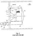
- a suction device comprising a longitudinal tangential trunk 30 ( Figures 1 , 2 and 4 ) extending along a generatrix of the cylinder 7.
- the horn 30 is fixed to the carrier plate 6 at one end ( Figure 2 ).
- the horn 30 has a cylindrical surface open over its entire height by a slot or opening 31 which is arranged axially, that is to say along the generatrices of said cylindrical surface and which faces the cylinder 7. The edges of the slot are then separated from each other to enlarge the latter.
- the cross section of the horn thus shaped has a U-shaped open profile whose opening is oriented towards the retaining elements of the filter element 10.
- the external volume of the cylinder 7 equipped with the filtering element 10 is circularly divided into compartments 32 by the parallel longitudinal partitions 12 forming the retaining elements.
- the horn 30 has, in plan, in a view taken from the cylinder 7, a rectangular contour equivalent or substantially greater than once that of such a compartment.
- the trunk 30 has an opening 31 facing the compartments 32 of the cylinder, which may be equipped with flexible lips 33, 34 to reduce the section, while allowing the occasional passage of larger bodies .
- the horn 30 is connected by a pipe 35 to a suction member such as a pump 40 attached to the wall 6, for example the downstream side thereof.
- the pipe 35 thus passes for example through the wall 6 and ensures the attachment of the horn 30 to the latter.
- the pump 40 fed for example by a cable (not shown), is chosen so as to pump large debris and, when necessary, a type also able to ensure a very high survival rate of fish. Water carrying debris, fish and other forms of aquatic life is discharged to its collection point by a pipe 50.
- the suction device comprises two horns respectively disposed on either side of the panel or cylindrical filter element, one downstream in the direction of the outflow, the other upstream. These two horns are arranged in correspondence with each other and both turned towards the cylindrical filter panel in cooperation with the relative rotational movement and a pump whose discharge is connected to the horn is arranged downstream.
- cylindrical filter panel a pump whose discharge is connected to the horn is arranged downstream.
- the exhaust pipe 50 comprises two debris concentrators (not shown) and a set of valves allowing an alternative service on one or the other of the concentrators.
- the evacuation pipe is devoid of concentrator and the water laden with debris and fish is discharged directly into a pipe or canal for a return to the natural environment.
- FIG. 1 to 3 there is shown an embodiment in which the suction device 30, 40 is fixed, while the drive means 17, 18, 19 are adapted to drive the cylindrical panel or filter element in rotation.
- the panel or filter element is fixed while the drive means are adapted to drive the suction device in rotation.
- the drive means are adapted / configured to drive in rotation both the suction device (s) (if there are several) and the cylindrical filter panel.
- the compartments or retaining elements have different adapted shapes (for example, a generally triangular shape for a cone), as well as the suction device.
- the operation of the sieve is as follows: when stopped, the filter cylinder 7 is stopped, the pump 40 does not work and the water flows through the filter element. The debris is stopped by the filter element 10 and retained in the longitudinal compartments 32 at the periphery of the cylinder.
- the pump 40 is started and the cylinder is rotated by the drive means 17, 18, 19.
- the cylinder rotates and the peripheral compartments 32 pass alternately in front of the opening 31 of the trunk 30.
- Each compartment is isolated from the general stream by the front of the trunk.
- the suction of the pump creates in the compartment a circulation in the opposite direction to that of normal sieving and with a speed of the same order.
- the debris is sucked into the horn 30, through the pump 40, and is evacuated via the pipe 50.
- the drive system 17, 18, 19 stops by the effect of a force limiter known per se and a rotation in the opposite direction is engaged, generally allowing to get rid of blocking debris.
- the washing pump 40 and the rotational movement are stopped at the end of the washing cycle.
- the pump used is of a suitable type and known per se.
- the operation is normally automatic and slaved to the pressure drop generated by the filter cylinder, that is to say, its fouling.
- Devices already known by themselves ensure the safety of the installation.
- the size of the debris to be sucked is limited by the inlet gate grille present in such intake structures. This debris can then be stored waiting for washing thanks to the dimension of compartments, especially at the distance between the surface of the filter element and the free end of the longitudinal partitions of said compartments.
- the filtration device or sieve according to the invention prevents any possibility of bypassing the system.
- Such a device / sieve according to the invention has the advantage of being introduced by sliding in vertical guides cooperating with structures carrying filters pass through chain.
- the filter element 10 may have openings of meshes of cylindrical, rectangular, square or slots with respective dimensions of the order of 10 x 10 to 0.5 x 0.5 mm.
- the device / sieve according to the invention also finds an application to the sluices having an inclination relative to the vertical plane.
Description
La présente invention se rapporte aux dispositifs de filtration tels que notamment des tamis à panneau filtrant équipant les prises d'eau, qu'il s'agisse de prises d'eau en rivière ou de prises en mer, pour arrêter les débris et particules véhiculés par l'eau à prélever.The present invention relates to filtration devices such as filter screen sieves fitted to water intakes, whether river intakes or catches at sea, to stop debris and particles carried by the water to be taken.
Généralement, un tamis pour prise d'eau est normalement disposé en aval d'une grille à barreaux écartés de plusieurs centimètres le protégeant des débris de grosses dimensions, soit isolément, soit en association avec un ou plusieurs autres tamis de même type appartenant à un même poste de tamisage.Generally, a sieve for water intake is normally placed downstream of a grid bars separated by several centimeters protecting it from large debris, either alone or in combination with one or more other sieves of the same type belonging to a same sieving station.
De manière connue, l'élément filtrant, dont les mailles n'ont que quelques millimètres d'ouverture, est généralement mobile afin d'être périodiquement débarrassé des débris et particules qui, de dimensions supérieures à celles de ces mailles, viennent progressivement obstruer la totalité de celles-ci et donc le colmater.In a known manner, the filtering element, whose mesh is only a few millimeters in aperture, is generally mobile so as to be periodically freed from debris and particles which, of dimensions larger than those of these meshes, gradually come to obstruct the all of them and therefore clog it.
Un tel élément filtrant mobile peut être constitué d'un panneau relevable dans son plan, en alternance avec un autre panneau de même type disposé parallèlement au précédent, à distance de ce dernier.Such a movable filter element may consist of a panel that can be raised in its plane, alternating with another panel of the same type arranged parallel to the previous one, at a distance from the latter.
Un tel élément filtrant peut également être constitué d'une boucle sans fin, de section transversale allongée, pour la constitution d'une chaîne filtrante, appelée encore filtre à chaîne à passage direct ou à double flux.Such a filter element may also consist of an endless loop of elongated cross section, for the constitution of a filter chain, also called direct flow or double flow chain filter.
Un tel élément filtrant peut aussi être constitué d'une boucle sans fin, de section transversale cylindrique ou polygonale pour la constitution d'un tambour filtrant.Such a filter element may also consist of an endless loop of cylindrical or polygonal cross section for the formation of a filter drum.
Quoiqu'il en soit, un tel élément filtrant mobile pour prise d'eau, qu'il s'agisse d'un tamis à panneau filtrant, d'une chaîne filtrante ou d'un tambour filtrant, passe cycliquement d'une position d'immersion dans laquelle il se charge progressivement en débris et particules divers, à une position d'émersion. Dans cette dernière position, il est soumis aux effets de jets d'eau sous pression agissant à contre-courant pour le débarrasser des particules et débris ainsi appliqués à sa surface et le rendre ainsi apte à assumer à nouveau sa fonction de filtration au cours de son immersion ultérieure.Anyway, such a movable filter element for water intake, whether it is a filter screen sieve, a filter chain or a filter drum, cyclically passes from a position d immersion in which it is gradually loaded with debris and various particles, at an emergent position. In the latter position, it is subject to the effects of water jets under pressure acting against the current to rid the particles and debris thus applied to its surface and thus make it able to assume its filter function again during its subsequent immersion.
Les particules et débris ainsi entraînés par l'eau de lavage sont usuellement recueillis globalement, dans un chéneau aménagé à cet effet et sont évacués à l'égout par celui-ci.The particles and debris thus entrained by the washing water are usually collected globally, in a gutter built for this purpose and are discharged to the sewer by it.
Si des poissons sont présents sur les panneaux, ils sont alors exondés et soumis à des impacts qui les tuent le plus souvent.If fish are present on the panels, they are then exposed and subjected to impacts that kill them most often.
De même, certaines fuites des panneaux entre eux, ou entre eux et les montants latéraux fixes de la charpente du filtre, peuvent se produire.Similarly, some of the panel leaks between them, or between them and the fixed side uprights of the filter frame, may occur.
Par ailleurs, les poissons, piégés ou entraînés par l'élément filtrant mobile d'un tamis à une telle prise d'eau, sont irrémédiablement soumis :
- à un séjour, souvent prolongé, hors d'eau, au cours de la phase d'émersion de cet élément filtrant,
- à l'action des jets d'eau de lavage appliqués à celui-ci, qui est le plus souvent brutale et
- à la projection violente qui en résulte, dans le chéneau prévu pour la récupération d'ensemble des particules et débris ayant temporairement colmaté l'élément filtrant en question.
- a stay, often prolonged, out of water, during the emergence phase of this filter element,
- to the action of wash water jets applied to it, which is most often brutal and
- to the resulting violent projection, in the gutter intended for the overall recovery of particles and debris having temporarily clogged the filter element in question.
Les filtres à chaîne à passage direct, c'est-à-dire les filtres à chaîne dont seule la face amont du tablier filtrant reçoit l'eau à filtrer, présentent également divers inconvénients, qui sont les suivants :
Tout d'abord, au fond du pertuis, il est nécessaire de prévoir, à la base du tablier filtrant, pour étanchéité entre celui-ci et ledit fond, une plaque d'étanchéité, dite plaque de pied, qui doit être tangente audit tablier.Chain filters with direct passage, that is to say the chain filters which only the upstream face of the filter deck receives the water to be filtered, also have various disadvantages, which are as follows:
First, at the bottom of the door, it is necessary to provide, at the base of the filtering deck, for sealing between the latter and said bottom, a sealing plate, said foot plate, which must be tangent to said deck .
Or, compte tenu des inévitables tolérances de fabrication et de montage et de l'usure des pièces et, notamment de celle des chaînes porte tablier, un jeu minimal subsiste toujours entre une telle plaque de pied et le tablier filtrant et, en pratique, ce jeu n'est jamais inférieur à environ 6 mm, il dépasse même souvent cette valeur.However, in view of the inevitable manufacturing and assembly tolerances and the wear of the parts and, in particular, that of the apron chains, a minimum clearance always remains between such a foot plate and the filtering apron and, in practice, game is never less than about 6 mm, it often exceeds this value.
Il en résulte que, par mesure de cohérence, les tabliers filtrants de tels filtres à chaîne à passage direct ne peuvent pas être équipés de mailles d'ouverture inférieure à 6 mm et que l'efficacité de l'épuration assurée s'en trouve limitée en conséquence.As a result, for the sake of consistency, the filtering aprons of such direct-pass chain filters can not be equipped with meshes less than 6 mm and that the effectiveness of the treatment provided is therefore limited accordingly.
En ce qui concerne les filtres à chaîne à double flux, le tablier filtrant possède des génératrices parallèles au sens de circulation du flot d'eau à filtrer.With regard to the double-flow chain filters, the filtering deck has generatrices parallel to the direction of flow of the stream of water to be filtered.
Les deux faces de ce tablier filtrant ont, en parallèle, des rôles identiques, soit que ledit flot circule de l'extérieur vers l'intérieur du tablier filtrant à travers l'une et l'autre des faces de celui-ci, soit qu'il circule en sens inverse.The two faces of this filtering deck have, in parallel, identical roles, ie that said flow flows from the outside to the inside of the filtering deck through one and the other of the faces thereof, or that it flows in the opposite direction.
La charpente porteuse de tels filtres à chaîne à double flux est usuellement adossée à des murets en maçonnerie établis l'un en regard de l'autre dans le pertuis à équiper.The framework carrying such filters with double flow chain is usually leaned against masonry walls established one facing the other in the pertu to equip.
De tels filtres à chaîne à double flux ont pour avantage, aucune étanchéité n'étant à prévoir au pied de leur tablier, de permettre la mise en oeuvre, pour celui-ci, de mailles d'ouverture réduite, inférieure par exemple à 0,5 mm, sans incohérence avec une quelconque autre lacune d'étanchéité.Such double-flow chain filters have the advantage, no sealing being to be expected at the foot of their apron, to allow the implementation, for it, meshes of reduced opening, for example less than 0, 5 mm, without inconsistency with any other sealing gap.
Ils ont également pour avantage de permettre une utilisation simultanée des deux faces de leur tablier et donc de dédoubler, à volume égal, la surface effective de filtration, c'est-à-dire la capacité de l'appareil.They also have the advantage of allowing simultaneous use of the two faces of their apron and thus to duplicate, at equal volume, the effective filtration surface, that is to say the capacity of the device.
Néanmoins, des filtres à chaîne à double flux n'apportent aucune amélioration à la survie des poissons par rapport aux filtres à chaîne à passage direct.Nonetheless, dual-flow chain filters provide no improvement in fish survival over direct-pass chain filters.
Il a certes été déjà proposé divers dispositifs destinés à l'équipement d'un poste de tamisage pour prise d'eau en vue d'assurer la sauvegarde des éléments vivants et, en particulier, des poissons, véhiculés par l'eau à prélever. Cependant, dans les réalisations de ce type connues à ce jour, il s'agit soit de filtres spéciaux, n'assurant par eux-mêmes que la sauvegarde du poisson sans une quelconque fonction générale de tamisage, soit de filtres de tamisage conventionnels imposant aux poissons recueillis un séjour hors d'eau.It has certainly been proposed various devices for the equipment of a sieving station for water intake to ensure the preservation of living elements and, in particular, fish, carried by the water to be taken. However, in the embodiments of this type known to date, they are either special filters, ensuring by themselves only the preservation of the fish without any general sieving function, or conventional sieving filters imposing fish collected a stay out of water.
La présente invention a donc d'une manière générale pour objet de permettre d'assurer une filtration ou tamisage notamment pour prise d'eau en n'ayant pas les inconvénients des structures antérieures et, le cas échéant, également d'assurer la sauvegarde des poissons.The present invention therefore generally aims to ensure filtration or sieving especially for water intake without the disadvantages of previous structures and, where appropriate, also to ensure the safeguarding of Pisces.
Par exemple, le document
Le document
De plus, pour les installations équipées actuellement de filtres à chaîne à passage direct, il se pose de plus en plus le problème d'améliorer l'efficacité de l'épuration en réduisant les dimensions des débris ou organismes susceptibles d'être retenus.In addition, for installations currently equipped with direct-flow chain filters, there is an increasing problem of improving the efficiency of purification by reducing the size of the debris or organisms that can be retained.
Mais à ce jour, leur substitution par des appareils assurant au moins la même fonction, sans en offrir les inconvénients et sans modification des ouvrages de génie civil ni désordre hydraulique ne peut pas non plus se faire aisément, les conditions matérielles d'implémentation de ceux-ci étant différentes.But to date, their substitution by devices ensuring at least the same function, without the disadvantages and without modification of civil engineering works or hydraulic disorder can not be done easily, the material conditions of implementation of those - being different.
Le tamis à panneau filtrant objet du brevet français déposé sous le numéro
Ainsi, la présente invention porte sur un dispositif de filtration ou tamis à élément filtrant à grande surface de filtration.Thus, the present invention relates to a filtration device or sieve with filter element with a large filtration surface.
Selon un premier aspect, l'invention vise une installation comprenant un canal dans lequel s'écoule de l'eau et un dispositif de filtration d'un écoulement d'eau dans le canal, le niveau de l'eau dans le canal étant situé entre un plus bas niveau des eaux (PBE) et un plus haut niveau des eaux (PHE), le dispositif comprenant :
- un tambour à élément filtrant monté sur la paroi formant châssis au droit de l'ouverture traversante et qui comporte une surface filtrante faisant saillie par rapport à la paroi vers l'amont, la surface filtrante étant une surface de révolution dont l'axe de révolution est disposé perpendiculairement à ladite ouverture traversante et ayant des dimensions supérieures à celles d'une surface filtrante plane qui serait aménagée dans l'ouverture traversante, l'élément filtrant comportant des éléments de retenue aménagés en vis-à-vis de la surface filtrante en amont de celle-ci ou en aval selon le sens de circulation de l'eau afin de retenir les corps solides qui ne traversent pas la surface filtrante,
- au moins un dispositif d'aspiration qui est disposé en regard des éléments de retenue et en amont de ceux-ci,
- des moyens d'entrainement de l'élément filtrant et/ou dudit au moins un dispositif d'aspiration dans un mouvement relatif de l'un par rapport à l'autre de manière à ce que ledit au moins un dispositif d'aspiration soit successivement amené en vis-à-vis de chaque élément de retenue afin d'engendrer localement, à travers l'élément filtrant, une circulation d'eau à contre-courant successivement au droit de chaque élément de retenue,
- a filter element drum mounted on the frame wall in line with the through opening and which has a filtering surface projecting from the upstream wall, the filtering surface being a surface of revolution whose axis of revolution is disposed perpendicular to said through opening and having dimensions greater than those of a plane filtering surface that would be arranged in the through opening, the filtering element having retaining elements arranged vis-à-vis the filtering surface upstream thereof or downstream in the direction of water flow in order to retain solid bodies that do not pass through the filtering surface,
- at least one suction device which is arranged opposite the retaining elements and upstream of these,
- means for driving the filter element and / or said at least one suction device in a relative movement relative to each other so that said at least one suction device is successively brought with respect to each retaining element in order to generate locally, through the filtering element, a flow of water countercurrently successively to the right of each retaining element,
Le dispositif de filtration peut ainsi être facilement installé dans un canal tel qu'un pertuis.The filtration device can thus be easily installed in a channel such as a sluice.
Un tel dispositif présente une surface de filtration bien plus grande que la surface filtrante circulaire du tamis de l'art antérieur susvisé, ce qui permet de traiter un grand débit d'eau.Such a device has a filtration surface much larger than the circular filtering surface of the sieve of the aforementioned prior art, which allows to treat a large flow of water.
La surface filtrante selon l'invention s'étend en effet à partir de la paroi formant châssis en formant une surface en trois dimensions (surface non plane) au lieu de la surface bidimensionnelle de l'art antérieur.The filtering surface according to the invention extends indeed from the frame wall forming a three-dimensional surface (non-planar surface) instead of the two-dimensional surface of the prior art.
Selon une caractéristique possible, la surface filtrante est cylindrique, ce qui accroît de façon particulièrement simple et considérable la taille de la surface filtrante de l'art antérieur. La hauteur de la surface cylindrique qui correspond à la dimension d'extension de celle-ci à partir de la paroi formant
châssis ou le diamètre de la surface cylindrique peut être ajusté en fonction de la capacité de filtrage/tamisage que l'on souhaite conférer au dispositif.According to one possible characteristic, the filtering surface is cylindrical, which increases in a particularly simple and considerable way the size of the filtering surface of the prior art. The height of the cylindrical surface that corresponds to the extension dimension of the latter from the wall forming
frame or the diameter of the cylindrical surface can be adjusted according to the filtering capacity / sieving that it is desired to give the device.
Si la hauteur de la surface cylindrique devient trop importante relativement au diamètre du cylindre, des efforts de flexion sont ainsi créés au pied de l'axe fixé à la paroi. Dans ces circonstances un support de l'extrémité libre de la surface peut être nécessaire afin d'éviter des déformations de celle-ci sous l'effet de son poids.If the height of the cylindrical surface becomes too large relative to the diameter of the cylinder, bending forces are thus created at the foot of the axis fixed to the wall. Under these circumstances a support of the free end of the surface may be necessary to prevent deformation thereof under the effect of its weight.
Selon une caractéristique possible, l'axe de révolution de la surface filtrante cylindrique est disposé perpendiculairement à l'ouverture traversante de la paroi formant châssis.According to a possible characteristic, the axis of revolution of the cylindrical filtering surface is arranged perpendicular to the through opening of the frame wall.
Cette configuration est particulièrement simple. La surface filtrante cylindrique est positionnée devant l'ouverture de la paroi et est ouverte à son extrémité qui fait face à l'ouverture afin que l'eau puisse traverser l'élément filtrant, pénétrer à l'intérieur du cylindre filtrant et s'échapper par l'ouverture vers l'aval de la paroi.This configuration is particularly simple. The cylindrical filter surface is positioned in front of the opening of the wall and is open at its end which faces the opening so that water can pass through the filter element, penetrate inside the filter cylinder and escape through the opening downstream of the wall.
Une circulation inverse de l'eau est également envisageable. On notera que dans ce cas les éléments de retenue sont disposés à l'intérieur de la surface filtrante cylindrique et non à l'extérieur.Reverse circulation of water is also possible. Note that in this case the retaining elements are disposed within the cylindrical filter surface and not outside.
Dans la configuration présentée ci-dessus l'extrémité libre de la surface filtrante est fermée afin de forcer l'écoulement d'eau à travers la surface filtrante cylindrique.In the configuration presented above, the free end of the filtering surface is closed in order to force the flow of water through the cylindrical filtering surface.
Selon une caractéristique possible, les éléments de retenue sont disposés parallèlement entre eux suivant des génératrices de la surface filtrante cylindrique.According to a possible characteristic, the retaining elements are arranged parallel to one another along generatrices of the cylindrical filtering surface.
Ces éléments forment ainsi des compartiments longitudinaux à la périphérie extérieure de la surface filtrante cylindrique.These elements thus form longitudinal compartments at the outer periphery of the cylindrical filtering surface.
Cet agencement de compartiments est particulièrement simple à réaliser et efficace.This arrangement of compartments is particularly simple to perform and effective.
Selon une caractéristique possible, les éléments de retenue précités sont formés par deux cloisons espacées parallèles entre elles, agencées suivant des génératrices de la surface filtrante cylindrique.According to a possible characteristic, the aforementioned retaining elements are formed by two partitions spaced parallel to each other, arranged along generatrices of the cylindrical filtering surface.
Ces cloisons longitudinales sont généralement régulièrement réparties autour de la surface filtrante.These longitudinal partitions are generally regularly distributed around the filtering surface.
Selon une autre forme de réalisation possible, la surface filtrante est conique et non cylindrique comme décrit ci-dessus.According to another possible embodiment, the filtering surface is conical and non-cylindrical as described above.
Dans cette autre configuration, la base du cône est en contact avec la paroi formant châssis et la surface filtrante conique s'étend en éloignement de la paroi, sensiblement perpendiculairement à cette dernière en direction de la pointe du cône.In this other configuration, the base of the cone is in contact with the frame wall and the conical filter surface extends away from the wall, substantially perpendicularly to the latter towards the tip of the cone.
On notera que la surface filtrante peut de façon alternative être tronconique.It will be noted that the filtering surface may alternatively be frustoconical.
Les éléments de retenue agencés sur la périphérie de la surface filtrante conique sont alors disposés suivant des génératrices du cône et forment ainsi, suivant une vue en plan, des compartiments de forme générale triangulaire dont la pointe du triangle est dirigée vers la pointe du cône.The retaining elements arranged on the periphery of the conical filtering surface are then arranged along generatrices of the cone and thus form, according to a plan view, compartments of generally triangular shape, the tip of the triangle is directed towards the tip of the cone.
Là aussi, l'augmentation de surface filtrante résultant d'une telle forme permet de traiter/tamiser un plus grand débit d'eau que la surface filtrante circulaire du tamis de l'art antérieur visé ci-dessus.Here again, the increase in filter area resulting from such a shape makes it possible to treat / sift a larger flow of water than the circular filtering surface of the sieve of the prior art referred to above.
On notera que dans le cas où une surface filtrante conique ou tronconique est utilisée avec une circulation d'eau inversée, c'est-à-dire que l'eau traverse d'abord l'ouverture dans la paroi formant châssis, puis pénètre à l'intérieur de la surface filtrante et traverse cette dernière pour ressortir en aval de celle-ci de l'autre côté du dispositif de filtration, les éléments de retenue sont disposés à l'intérieur de la surface conique et non à l'extérieur.Note that in the case where a conical or frustoconical filtering surface is used with an inverted water circulation, that is to say that the water first passes through the opening in the frame wall, then enters the inside of the filtering surface and through the latter to exit downstream thereof on the other side of the filter device, the retaining elements are disposed within the conical surface and not outside.
Selon une autre caractéristique possible, l'élément filtrant est mobile tandis que ledit au moins un dispositif d'aspiration est fixe.According to another possible feature, the filter element is movable while said at least one suction device is fixed.
Selon une autre caractéristique alternative possible, l'élément filtrant est fixe tandis que ledit au moins un dispositif d'aspiration est mobile.According to another possible alternative characteristic, the filter element is stationary while said at least one suction device is movable.
Selon encore une autre caractéristique alternative possible, l'élément filtrant et ledit au moins un dispositif d'aspiration sont mobiles.According to yet another alternative characteristic possible, the filter element and said at least one suction device are movable.
On notera que, quelle que soit la forme de réalisation présentée ci-dessus, un mouvement relatif doit s'établir entre l'élément filtrant (quelle que soit la forme de la surface filtrante) et le ou les dispositifs d'aspiration afin que ce ou ces derniers soient successivement amenés en vis-à-vis de chaque élément de retenue pour aspirer les divers corps solides arrêtés par la surface filtrante.It should be noted that, whatever the embodiment presented above, a relative movement must be established between the filtering element (whatever the shape of the filtering surface) and the suction device or devices so that this or they are successively brought vis-à-vis each retaining element to suck the various solid bodies stopped by the filtering surface.
Selon une caractéristique possible, les moyens d'entrainement sont adaptés pour entrainer en rotation l'élément filtrant, le ou les dispositifs d'aspiration ou les deux.According to a possible characteristic, the drive means are adapted to rotate the filter element, the suction device or both.
On notera que dans la forme de réalisation où l'élément filtrant et le ou les dispositifs d'aspiration sont mobiles, des moyens d'entrainement distincts sont prévus pour entrainer en mouvement chacun de ceux-ci.Note that in the embodiment where the filter element and the suction device or devices are movable, separate drive means are provided to drive each of them in motion.
Le mouvement de rotation du ou des éléments précités est un mouvement particulièrement simple à effectuer.The rotational movement of the aforementioned element or elements is a particularly simple movement to perform.
Selon une autre caractéristique possible, le dispositif d'aspiration ou chaque dispositif d'aspiration s'il y en a plusieurs, comprend un organe d'aspiration (par exemple: pompe, éjecteur, écoulement gravitaire...) et une trompe d'aspiration, un organe d'aspiration (par exemple : pompe) pouvant être commun à plusieurs trompes.According to another possible characteristic, the suction device or each suction device if there are several, comprises a suction member (for example: pump, ejector, gravity flow ...) and a suction horn, a suction member (for example: pump) that can be common to several horns.
La trompe d'aspiration est destinée à être positionnée en regard des éléments de retenue et à balayer successivement chacun d'eux lors du mouvement relatif entre le dispositif d'aspiration et l'élément filtrant.The aspiration horn is intended to be positioned opposite the retaining elements and to successively scan each of them during the relative movement between the suction device and the filter element.
Selon une autre caractéristique possible, la trompe d'aspiration a une forme générale allongée et comprend une paroi formant enveloppe qui présente, en section transversale, un profil ouvert doté d'une ouverture en vis-à-vis des éléments de retenue. Par exemple, l'ouverture est pratiquée dans une lèvre cintrée parallèle et tangente à la surface filtrante, solidaire de l'organe d'aspiration. Cette lèvre cintrée empêche que l'eau aspirée soit de l'eau non filtrée qui a contourné l'organe d'aspiration et non de l'eau provenant de l'intérieur duAccording to another possible feature, the suction horn has a generally elongated shape and comprises an envelope wall which has, in cross section, an open profile with an opening vis-à-vis the retaining elements. For example, the opening is made in a curved lip parallel and tangent to the filtering surface, integral with the suction member. This curved lip prevents the water drawn from being unfiltered water that has bypassed the suction member and not water from inside the
Une telle forme est par exemple obtenue à partir d'une plaque de forme sensiblement rectangulaire qui serait cintrée autour d'un cylindre afin d'amener les deux bords longitudinaux de la plaque (grands côtés) en regard l'un de l'autre mais à distance, pour ménager une ouverture entre ces derniers.Such a shape is for example obtained from a plate of substantially rectangular shape which would be bent around a cylinder in order to bring the two longitudinal edges of the plate (long sides) opposite one another but remotely, to provide an opening between them.
Il convient d'ailleurs de noter qu'une autre méthode pour former une telle trompe d'aspiration peut consister à réaliser une fente dans un tube cylindrique creux, sur toute la hauteur de ce dernier, puis à écarter légèrement les bords libres encadrant la fente axiale ainsi formée de manière à agrandir celle-ci et à obtenir la forme souhaitée.It should also be noted that another method for forming such a suction tube may consist in making a slot in a hollow cylindrical tube, over the entire height of the latter, then slightly spreading the free edges flanking the slot axial so formed to enlarge it and to obtain the desired shape.
Selon une caractéristique possible, le profil ouvert a une forme générale de U ou de C.According to one possible characteristic, the open profile has a general U or C shape.
Un tel profil est particulièrement adapté à coopérer avec les éléments de retenue de l'élément filtrant.Such a profile is particularly adapted to cooperate with the retaining elements of the filter element.
Selon une caractéristique possible, l'ouverture présente, en plan, un contour sensiblement rectangulaire de dimensions égales ou supérieures à celles des éléments de retenue en regard.According to a possible characteristic, the opening has, in plan, a substantially rectangular contour of dimensions equal to or greater than those of the retaining elements opposite.
Une telle ouverture est particulièrement bien adaptée à la configuration des éléments de retenue de l'élément filtrant doté d'une surface de filtration cylindrique.Such an opening is particularly well suited to the configuration of the retaining elements of the filter element having a cylindrical filtration surface.
Le dispositif de filtration peut ainsi être facilement installé dans un canal tel qu'un pertuis.The filtration device can thus be easily installed in a channel such as a sluice.
Des caractéristiques et avantages mentionnés ci-dessus à propos du dispositif de filtration s'appliquent également à l'installation visée ci-dessus.The above-mentioned features and advantages of the filtration device also apply to the installation referred to above.
Selon une configuration possible plus particulière du dispositif de l'invention, le dispositif/tamis comprend un châssis propre à se raccorder à une prise d'eau et un panneau filtrant cylindrique interposé axialement dans une ouverture cylindrique dudit châssis, en étant solidaire dudit châssis, ledit panneau cylindrique filtrant comportant un cylindre à axe horizontal et comportant des éléments de retenue longitudinaux qui sont disposés, en amont du panneau filtrant cylindrique et solidaires de celui-ci. Un dispositif d'aspiration, est disposé en amont des éléments de retenue et des moyens d'entraînement du panneau cylindrique et/ou du dispositif d'aspiration selon un mouvement rotatif relatif sont prévus de manière à engendrer localement, à travers le panneau filtrant cylindrique, une circulation à contre-courant successivement au droit de chaque élément de retenue, selon ledit mouvement rotatif relatif, pour reprendre successivement les débris et particules retenus par ceux-ci et les diriger à travers une conduite d'évacuation apte à évacuer lesdits débris et particules ainsi prélevés vers l'extérieur.According to a more particular possible configuration of the device of the invention, the device / sieve comprises a frame adapted to be connected to a water intake and a cylindrical filter panel interposed axially in a cylindrical opening of said chassis, being integral with said chassis, said cylindrical filter panel having a cylinder with a horizontal axis and having longitudinal retaining elements which are arranged, upstream of the cylindrical filter panel and secured thereto. A suction device is arranged upstream of the retaining elements and drive means of the cylindrical panel and / or the suction device in a relative rotational movement are provided so as to generate locally, through the cylindrical filter panel countercurrent circulation successively to the right of each retaining element, according to said relative rotational movement, to successively recover the debris and particles retained by them and direct them through an evacuation pipe able to evacuate said debris and particles thus taken outwards.
Selon une première réalisation possible, le panneau filtrant cylindrique est fixe tandis que les moyens d'entraînement sont adaptés pour entraîner le dispositif d'aspiration cylindrique en rotation.According to a first possible embodiment, the cylindrical filter panel is fixed while the drive means are adapted to drive the cylindrical suction device in rotation.
Selon une seconde réalisation possible, le dispositif d'aspiration est fixe tandis que les moyens d'entraînement sont adaptés pour entraîner le panneau filtrant cylindrique en rotation.According to a second possible embodiment, the suction device is fixed while the drive means are adapted to drive the cylindrical filter panel in rotation.
Selon une troisième réalisation possible, les moyens d'entraînement sont adaptés pour entraîner en rotation le dispositif d'aspiration et le panneau filtrant cylindrique.According to a third possible embodiment, the drive means are adapted to drive in rotation the suction device and the cylindrical filter panel.
En pratique, le dispositif d'aspiration comprend une pompe d'aspiration et une trompe d'aspiration.In practice, the suction device comprises a suction pump and a suction pump.
De préférence, le volume externe du panneau filtrant cylindrique est fragmenté circulairement en compartiments par des cloisons longitudinales formant les éléments de retenue et la trompe d'aspiration comporte, en plan, un contour rectangulaire équivalent ou sensiblement supérieur à une fois celui d'un tel compartiment.Preferably, the external volume of the cylindrical filter panel is circularly divided into compartments by longitudinal partitions forming the retaining elements and the suction horn comprises, in plan, a rectangular contour equivalent to or substantially greater than once that of such compartment.
En variante, le dispositif d'aspiration comprend deux trompes disposées respectivement de part et d'autre du panneau filtrant cylindrique, l'une en aval dans le sens du flux sortant, l'autre en amont, établies en correspondance l'une avec l'autre et tournées l'une et l'autre vers le panneau filtrant cylindrique en coopération avec le mouvement rotatif relatif et une pompe dont le refoulement est raccordé à la trompe disposée en aval du panneau filtrant cylindrique.In a variant, the suction device comprises two horns disposed respectively on either side of the cylindrical filter panel, one downstream in the direction of the outgoing flow, the other upstream, established in correspondence with each other. and both are rotated to the cylindrical filter panel in cooperation with the relative rotational movement and a pump whose delivery is connected to the horn arranged downstream of the cylindrical filter panel.
Dans une configuration sans poisson à sauvegarder, la conduite d'évacuation peut comprendre, en outre, au moins un concentrateur de débris.In a fishless configuration to be saved, the exhaust pipe may further comprise at least one debris concentrator.
Selon une réalisation, la conduite d'évacuation comprend deux concentrateurs à débris et un jeu de vannes permettant un service alternatif sur l'un ou l'autre des concentrateurs.In one embodiment, the exhaust pipe includes two debris concentrators and a set of valves allowing alternative service to one or other of the concentrators.
Dans une configuration avec poissons à sauvegarder, la conduite d'évacuation est dépourvue de concentrateur et l'eau, chargée de débris et de poissons, est déversée directement dans une conduite ou un canal pour un retour au milieu naturel.In a configuration with fish to back up, the evacuation pipe is devoid of concentrator and the water, laden with debris and fish, is discharged directly into a pipe or channel for a return to the natural environment.
En pratique, la position basse du cylindre filtrant circulaire correspond sensiblement au fond d'un pertuis ainsi équipé, tandis que la position haute du panneau filtrant cylindrique est, si possible, à un niveau inférieur à celui des basses eaux.In practice, the low position of the circular filter cylinder substantially corresponds to the bottom of a well equipped sluice, while the high position of the cylindrical filter panel is, if possible, at a lower level than the low water level.
Selon un autre aspect de l'invention, le tamis comprend au moins deux panneaux filtrants cylindriques superposés l'un sur l'autre dans le plan vertical, entre la position basse et la position haute, chaque dispositif d'aspiration étant relié à une évacuation commune ou séparée et l'entraînement des panneaux filtrants cylindriques étant réalisé par des moyens d'entraînement séparés ou communs aux deux panneaux filtrants cylindriques.According to another aspect of the invention, the screen comprises at least two cylindrical filter panels superimposed on each other in the vertical plane, between the low position and the high position, each suction device being connected to an evacuation common or separate and the driving of the cylindrical filter panels being achieved by drive means separate or common to the two cylindrical filter panels.
Selon encore une autre réalisation, le tamis est destiné à être logé en lieu et place d'un filtre à chaîne à passage direct formé d'un canal constitué d'un fond et de deux murs latéraux rectilignes où sont scellés des guides verticaux, dans lesquels la charpente du filtre à passage direct est susceptible de glisser et une ouverture rectangulaire au plancher de service bordé généralement sur son côté amont par un caniveau destiné au recueil des détritus projetés par les jets de lavage et un fond d'ouvrage plat, ledit tamis selon l'invention étant apte à coopérer avec l'ouvrage de génie civil dudit filtre à passage direct.According to yet another embodiment, the screen is intended to be housed instead of a direct-pass chain filter formed by a channel consisting of a bottom and two rectilinear side walls which are sealed vertical guides, in which the frame of the direct-pass filter is capable of sliding and a rectangular opening to the service floor generally bordered on its upstream side by a gutter for the collection of detritus projected by the washing jets and a flat work base, said sieve according to the invention being able to cooperate with the civil engineering structure of said direct-pass filter.
D'autres caractéristiques et avantages de l'invention apparaîtront à la lumière de la description détaillée ci-après et des dessins dans lesquels :
- la
Figure 1 est une vue en coupe transversale d'un pertuis de prise d'eau équipé d'un dispositif/tamis à panneau filtrant cylindrique selon l'invention, vue de l'amont ; - la
Figure 2 est une vue en élévation-coupe en section horizontale selon la coupe BB de laFigure 1 ; - la
Figure 3 est une vue en coupe horizontale suivant la section CC de laFigure 1 ; et - la
Figure 4 reprend à plus grande échelle les détails D et E desFigures 1 et2 .
- the
Figure 1 is a cross-sectional view of a water intake opening equipped with a device / sieve with a cylindrical filter panel according to the invention, seen from upstream; - the
Figure 2 is an elevation-section view in horizontal section according to section BB of theFigure 1 ; - the
Figure 3 is a horizontal sectional view along section CC of theFigure 1 ; and - the
Figure 4 resumes on a larger scale the details D and E of theFigures 1 and2 .
Tel qu'illustré sur les Figures, un dispositif de filtration à élément filtrant ayant une surface de filtration cylindrique tel qu'un tamis 1 à panneau filtrant cylindrique est installé dans un canal ou pertuis 2 de prise d'eau dont les parois 3 et 4 de maçonnerie parallèles comportent chacune, en regard l'une de l'autre, un guide vertical 5 (
De tels guides 5 sont par exemple réalisés en métal et forment chacun une rainure ainsi que représenté à la
Le pertuis 2 est équipé d'une plaque porteuse ou paroi formant châssis 6 s'étendant d'un mur 3 à l'autre 4 et qui est glissée verticalement dans les guides 5. La plaque 6 comporte une ouverture circulaire centrée sensiblement sur l'axe 13 de la plaque 6. La partie basse de l'ouverture circulaire est située le plus généralement très près du fond 14 du pertuis 2. L'ouverture circulaire est obstruée par un cylindre 7 concentrique à l'ouverture et qui fait saillie par rapport à la plaque porteuse ou châssis 6 vers l'amont (
Le diamètre du cylindre 7 est de préférence le plus grand possible, c'est-à-dire légèrement inférieur à la largeur du pertuis 2, ceci afin d'augmenter le plus possible la surface de filtration. La hauteur du cylindre peut aussi être ajustée et augmentée si besoin est. Toutefois, pour éviter un fléchissement d'un cylindre trop haut sous l'action de son poids qui, normalement, nécessiterait de supporter l'extrémité libre du cylindre, on peut préférer augmenter le diamètre du cylindre.The diameter of the cylinder 7 is preferably the largest possible, that is to say slightly less than the width of the sluice 2, in order to increase the filtration area as much as possible. The height of the cylinder can also be adjusted and increased if necessary. However, to avoid a bending of a cylinder too high under the action of its weight which normally would require to support the free end of the cylinder, it may be preferred to increase the diameter of the cylinder.
On notera que l'eau s'écoule comme indiqué par les flèches sur la
En variante, l'eau s'écoule de l'intérieur du cylindre filtrant vers l'extérieur et les éléments de retenue sont disposés à l'intérieur du cylindre filtrant.Alternatively, the water flows from the inside of the filter cylinder outwards and the retaining elements are disposed inside the filter cylinder.
Le niveau le plus bas des eaux noté PBE est généralement situé au moins au niveau supérieur du cylindre (
Le moyeu 9 du cylindre est muni de paliers et de butées mécaniques connus par eux-mêmes. Le moyeu 9 est porté par un arbre 15 fixé à la plaque ou paroi support 6 par des bras radiaux 16.The
Afin d'empêcher l'eau de passer de l'amont vers l'aval du cylindre filtrant 7 sans passer par l'élément filtrant 10, la plaque 6 s'étend au moins jusqu'à un niveau généralement égal ou supérieur au niveau des plus hautes eaux PHE non représenté sur les figures.In order to prevent water from passing upstream to downstream of the filter roll 7 without passing through the
Comme représenté sur la
Le cylindre 7, centré par le moyeu 9, est entraîné en rotation par des moyens d'entraînement comportant une denture d'engrenage périphérique 17, un pignon 18 et un moteur d'entraînement 19 (
On notera qu'un joint d'étanchéité à lèvre 20 est par exemple prévu entre l'extrémité 7b du cylindre filtrant et la paroi ou plaque 6.Note that a
En variante, l'élément filtrant 10 protubérant par rapport à la plaque ou paroi 6 est conique avec la base du cône située en regard de l'ouverture de la plaque ou paroi 6 et la pointe du cône dirigée vers l'amont.Alternatively, the
Il est adjoint au cylindre filtrant un dispositif d'aspiration comprenant une trompe longitudinale tangentielle 30 (
Comme représenté sur la
En pratique, le volume externe du cylindre 7 équipé de l'élément filtrant 10 est fragmenté circulairement en compartiments 32 par les cloisons longitudinales parallèles 12 formant les éléments de retenue. La trompe 30 a, en plan, suivant une vue prise depuis le cylindre 7, un contour rectangulaire équivalent ou sensiblement supérieur à une fois celui d'un tel compartiment.In practice, the external volume of the cylinder 7 equipped with the
La trompe 30 a une ouverture 31 orientée en vis-à-vis des compartiments 32 du cylindre, qui peut être équipée de lèvres souples 33, 34 afin d'en réduire la section, tout en permettant le passage occasionnel de corps de plus grandes dimensions. La trompe 30 est reliée par une conduite 35 à un organe d'aspiration tel qu'une pompe 40 fixée à la paroi 6, par exemple du côté aval de celle-ci. La conduite 35 traverse ainsi par exemple la paroi 6 et assure la fixation de la trompe 30 à cette dernière.The
La pompe 40, alimentée par exemple par un câble (non représenté), est choisie de manière à pouvoir pomper de gros débris et, lorsque nécessaire, d'un type également apte à assurer un très fort taux de survie des poissons. L'eau véhiculant débris, poissons et autres formes de vie aquatique est évacuée vers son point de collecte par une conduite 50.The
En variante, le dispositif d'aspiration comprend deux trompes disposées respectivement de part et d'autre du panneau ou élément filtrant cylindrique, l'une en aval dans le sens du flux sortant, l'autre en amont. Ces deux trompes sont agencées en correspondance l'une avec l'autre et tournées l'une et l'autre vers le panneau filtrant cylindrique en coopération avec le mouvement rotatif relatif et une pompe dont le refoulement est raccordé à la trompe est disposée en aval du panneau filtrant cylindrique.Alternatively, the suction device comprises two horns respectively disposed on either side of the panel or cylindrical filter element, one downstream in the direction of the outflow, the other upstream. These two horns are arranged in correspondence with each other and both turned towards the cylindrical filter panel in cooperation with the relative rotational movement and a pump whose discharge is connected to the horn is arranged downstream. cylindrical filter panel.
Selon une autre variante, la conduite d'évacuation 50 comprend deux concentrateurs à débris (non représentés) et un jeu de vannes permettant un service alternatif sur l'un ou l'autre des concentrateurs.According to another variant, the
Dans une configuration avec poissons à sauvegarder, la conduite d'évacuation est dépourvue de concentrateur et l'eau chargée de débris et de poissons est déversée directement dans une conduite ou un canal pour un retour au milieu naturel.In a configuration with fish to back up, the evacuation pipe is devoid of concentrator and the water laden with debris and fish is discharged directly into a pipe or canal for a return to the natural environment.
Sur les
En variante (non représentée), le panneau ou élément filtrant est fixe tandis que les moyens d'entraînement sont adaptés pour entraîner le dispositif d'aspiration en rotation.Alternatively (not shown), the panel or filter element is fixed while the drive means are adapted to drive the suction device in rotation.
Selon une autre variante (non représentée), les moyens d'entraînement sont adaptés/configurés pour entraîner en rotation à la fois le ou les dispositifs d'aspiration (s'il y en a plusieurs) et le panneau filtrant cylindrique.According to another variant (not shown), the drive means are adapted / configured to drive in rotation both the suction device (s) (if there are several) and the cylindrical filter panel.
Ce qui vient d'être décrit concernant notamment les compartiments, le ou les dispositifs d'aspiration, le mouvement relatif entre ce(s) dernier(s) et l'élément filtrant s'applique quelle que soit la forme de l'élément filtrant.What has just been described concerning in particular the compartments, the suction device (s), the relative movement between the latter (s) and the filtering element applies whatever the shape of the filter element .
Toutefois, pour un élément filtrant de forme non cylindrique les compartiments ou éléments de retenue ont des formes différentes adaptées (par exemple, une forme générale triangulaire pour un cône), de même que le dispositif d'aspiration.However, for a filter element of non-cylindrical shape the compartments or retaining elements have different adapted shapes (for example, a generally triangular shape for a cone), as well as the suction device.
Le fonctionnement du tamis est le suivant : à l'arrêt, le cylindre filtrant 7 est arrêté, la pompe 40 ne fonctionne pas et l'eau circule à travers l'élément filtrant. Les débris sont arrêtés par l'élément filtrant 10 et retenus dans les compartiments longitudinaux 32 en périphérie du cylindre. Lorsque l'on veut nettoyer le filtre 7, la pompe 40 est mise en route et le cylindre est mis en rotation par les moyens d'entraînement 17, 18, 19. Le cylindre tourne et les compartiments périphériques 32 passent tour à tour devant l'ouverture 31 de la trompe 30. Chaque compartiment est isolé du flot général par la façade de la trompe. L'aspiration de la pompe crée dans le compartiment une circulation en sens inverse de celui du tamisage normal et avec une vitesse du même ordre. Les débris sont aspirés dans la trompe 30, à travers la pompe 40, et sont évacués par la conduite 50.The operation of the sieve is as follows: when stopped, the filter cylinder 7 is stopped, the
Si un débris de grandes dimensions situé dans un compartiment 32 bloque la rotation du cylindre, le système d'entraînement 17, 18, 19 s'arrête par l'effet d'un limiteur d'effort connu en soi et une rotation en sens inverse est enclenchée, permettant généralement de se débarrasser du débris bloquant.If a large debris located in a
La pompe de lavage 40 et le mouvement de rotation sont arrêtés en fin de cycle de lavage.The
Lorsqu'il s'agit de récupérer vivants les poissons et autres formes de vie aquatique arrêtés sur le cylindre filtrant, la pompe utilisée est d'un type adapté et connu en soi. Le fonctionnement est normalement automatique et asservi à la perte de charge engendrée par le cylindre filtrant, c'est-à-dire à son encrassement. Des dispositifs déjà connus par eux-mêmes assurent la sécurité de l'installation.When it comes to recover live fish and other aquatic life forms stopped on the filter cylinder, the pump used is of a suitable type and known per se. The operation is normally automatic and slaved to the pressure drop generated by the filter cylinder, that is to say, its fouling. Devices already known by themselves ensure the safety of the installation.
La taille des débris à aspirer est limitée par la grille à barreaux d'entrée présente dans de tels ouvrages de prise d'eau. Ces débris peuvent alors être stockés en attente de lavage grâce à la dimension des compartiments, notamment à la distance entre la surface de l'élément filtrant et l'extrémité libre des cloisons longitudinales desdits compartiments.The size of the debris to be sucked is limited by the inlet gate grille present in such intake structures. This debris can then be stored waiting for washing thanks to the dimension of compartments, especially at the distance between the surface of the filter element and the free end of the longitudinal partitions of said compartments.
Il est à noter que le dispositif de filtration ou tamis selon l'invention empêche toute possibilité de contournement du système.It should be noted that the filtration device or sieve according to the invention prevents any possibility of bypassing the system.
Il n'engendre pas non plus de turbulences significatives dans le flot sortant. Il est donc plus efficace qu'un filtre à chaîne à double flux.Neither does it generate significant turbulence in the outflow. It is therefore more efficient than a double-flow chain filter.
Un tel dispositif/tamis selon l'invention a l'avantage de pouvoir être introduit par glissement dans des guides verticaux coopérant avec des structures porteuses de filtres à chaîne à passage direct.Such a device / sieve according to the invention has the advantage of being introduced by sliding in vertical guides cooperating with structures carrying filters pass through chain.
L'élément filtrant 10 peut présenter des ouvertures de mailles de forme cylindrique, rectangulaire, carrée ou de fentes avec des dimensions respectives de l'ordre de 10 x 10 à 0,5 x 0,5 mm.The
Le dispositif/tamis selon l'invention trouve également une application aux pertuis présentant une inclinaison par rapport au plan vertical.The device / sieve according to the invention also finds an application to the sluices having an inclination relative to the vertical plane.
Il peut même être monté avec l'axe vertical et une sortie en tunnel sous le plancher.It can even be mounted with the vertical axis and a tunnel exit under the floor.
Claims (13)
- An installation comprising a channel in which water flows and a device for filtering the stream of water in the channel (2), the water level in the channel being situated between a lowest water level (PBE) and a highest water level (PHE), the device comprising:- a frame-forming wall (6) mounted in the channel and which comprises a through-opening,- a drum with a filter member (10) mounted on the frame-forming wall opposite the through-opening and which comprises a filter surface projecting relative to the wall in the upstream direction, the filter surface being a surface of revolution of which the axis of revolution is disposed perpendicularly to said through-opening and having a larger area than would have a flat filter surface fitted in the through-opening, the filter member comprising retaining members (32) provided face to face with the filter surface upstream thereof, in order to retain the solid bodies that do not pass through the filter surface,- at least one suction device (30, 40) which is disposed opposite the retaining members upstream thereof,- means (17, 18, 19) for driving the filter member and/or said at least one suction device in a relative movement between them such that said at least one suction device is successively brought face to face with each retaining member in order to locally generate, through the filter member, a counter-flow of water successively opposite each retaining member,the installation being configured such that the upper level of the drum is situated at a maximum at the lowest level of the water (PBE)
- An installation according to claim 1, characterized in that the filter surface is cylindrical.
- An installation according to claim 2, characterized in that the retaining members are disposed parallel to each other along generatrices of the cylindrical filter surface.
- An installation according to claim 3, characterized in that the retaining members are formed by two partitions (12) spaced apart parallel to each other, arranged along generatrices of the cylindrical filter surface.
- An installation according to claim 1, characterized in that the filter surface is conical.
- A device according to one of claims 1 to 5, characterized in that the filter member is movable whereas said at least one suction device is fixed.
- An installation according to one of claims 1 to 5, characterized in that the filter member is fixed whereas said at least one suction device is movable.
- An installation according to one of claims 1 to 5, characterized in that the filter member and said at least one suction device are movable.
- An installation according to one of claims 6 to 8, characterized in that the drive means (17, 18, 19) are adapted to rotationally drive the filter member, said at least one suction device, or both.
- An installation according to one of claims 1 to 9, characterized in that the suction device or each suction device if there are several of them, comprises a suction unit (40) and a suction nozzle (30), it being possible for one suction unit to be common to several nozzles.
- An installation according to claims 2 and 10, characterized in that the suction nozzle (30) is of elongate general shape and comprises an envelope-forming wall which, in cross-section, has an open profile provided with an opening (31) face to face with the retaining members.
- An installation according to claim 11, characterized in that the general shape of the open profile is that of a U or a C.
- An installation according to claim 11 or 12, characterized in that, in plan view, the opening (31) has a substantially rectangular outline of dimensions equal to or greater than those of the facing retaining members.
Applications Claiming Priority (2)
| Application Number | Priority Date | Filing Date | Title |
|---|---|---|---|
| FR1157082A FR2978677B1 (en) | 2011-08-02 | 2011-08-02 | CYLINDRICAL FILTER PANEL SIEVES FOR WATER TAKING |
| US201161529408P | 2011-08-31 | 2011-08-31 |
Publications (2)
| Publication Number | Publication Date |
|---|---|
| EP2554231A1 EP2554231A1 (en) | 2013-02-06 |
| EP2554231B1 true EP2554231B1 (en) | 2018-12-05 |
Family
ID=46581852
Family Applications (1)
| Application Number | Title | Priority Date | Filing Date |
|---|---|---|---|
| EP12178819.4A Not-in-force EP2554231B1 (en) | 2011-08-02 | 2012-08-01 | Screen with cylindrical filter panel for water intake |
Country Status (6)
| Country | Link |
|---|---|
| US (3) | US9968872B2 (en) |
| EP (1) | EP2554231B1 (en) |
| CA (1) | CA2784621A1 (en) |
| CL (1) | CL2012002122A1 (en) |
| ES (1) | ES2713492T3 (en) |
| FR (1) | FR2978677B1 (en) |
Families Citing this family (17)
| Publication number | Priority date | Publication date | Assignee | Title |
|---|---|---|---|---|
| US20120223028A1 (en) * | 2009-11-12 | 2012-09-06 | Filter Safe Ltd. | Filter proximity nozzle |
| US8647516B2 (en) * | 2010-09-03 | 2014-02-11 | Johnny Leon LOVE | Filtration method with self-cleaning filter assembly |
| US8297448B2 (en) * | 2010-11-22 | 2012-10-30 | Johnson Screens, Inc. | Screen intake device for shallow water |
| FR2978677B1 (en) * | 2011-08-02 | 2014-10-17 | Beaudrey & Cie | CYLINDRICAL FILTER PANEL SIEVES FOR WATER TAKING |
| US20140116965A1 (en) * | 2012-11-01 | 2014-05-01 | Machinerie Agricole Bois-Francs Inc. | Separator and method for separating a heterogeneous supply |
| US9567719B2 (en) * | 2013-04-03 | 2017-02-14 | Laitram, L.L.C. | Aquatic life and debris collection device for a water screen |
| NL2012621B1 (en) * | 2014-04-15 | 2016-05-09 | Van Den Berg Bart | Drum filter for water filtration and method thereof. |
| SE539965C2 (en) * | 2015-06-23 | 2018-02-13 | Veolia Water Solutions & Tech | Filter panel with a controlled liquid lift, and a drum filter for filtering liquid |
| GB2551317A (en) * | 2016-06-07 | 2017-12-20 | Ide Technologies Ltd | Environmentally friendly water intake and pretreatment system |
| DE102017100952A1 (en) * | 2017-01-18 | 2018-07-19 | Aqseptence Group Gmbh | Screening device with pivotable screen fields |
| US10195549B1 (en) * | 2017-11-21 | 2019-02-05 | Aqua-Aerobic Systems, Inc. | Backwash shoe method and apparatus that increases effective surface area of cloth filter media |
| CN108360657A (en) * | 2018-02-10 | 2018-08-03 | 浙江泉峰建筑园林有限公司 | A kind of civic building discharge structure |
| CA3077753A1 (en) * | 2019-04-12 | 2020-10-12 | Cameron Farms Hutterite Colony | Fluid pumping apparatus and methods of use |
| KR102183820B1 (en) * | 2020-03-10 | 2020-11-30 | 주식회사 그레넥스 | Back wash device for fabric filtration apparatus |
| FR3113071A1 (en) | 2020-07-30 | 2022-02-04 | Eugene B | CIVIL WORKS AND WATER INTAKE FILTRATION SYSTEM |
| CN112127460B (en) * | 2020-09-27 | 2021-12-10 | 凤阳县和裕市政园林工程有限公司 | Sewer anti-blocking device suitable for different water levels |
| CN113332789A (en) * | 2021-08-05 | 2021-09-03 | 临沂盛荣环保科技有限公司 | Waste water environmental protection processing apparatus |
Family Cites Families (51)
| Publication number | Priority date | Publication date | Assignee | Title |
|---|---|---|---|---|
| US1516693A (en) * | 1924-11-25 | Newcastle-upon-tyne | ||
| US2142737A (en) * | 1939-01-03 | Sewage screening apparatus | ||
| DE637108C (en) * | 1936-10-21 | Josef Moehring | Cleaning device for the wall of a sieve drum used for desludging waste water | |
| FR406776A (en) | 1909-09-04 | 1910-02-10 | Europ Brake Shoe C | Advanced process for melting metals |
| US1210759A (en) * | 1914-02-07 | 1917-01-02 | Johannes Paul Breddin | Apparatus for purifying sewage-water. |
| US1188340A (en) * | 1916-02-12 | 1916-06-20 | Sewage Clarification Company | Filtration apparatus and system. |
| US2013971A (en) * | 1928-05-04 | 1935-09-10 | Municipal Sanitary Service Cor | Automatic screening and filtering apparatus |
| US2022336A (en) * | 1935-01-30 | 1935-11-26 | Joseph E Bower | Self cleaning screen |
| US2295937A (en) * | 1939-12-05 | 1942-09-15 | Louis E Crane | Screen separator |
| DE734268C (en) * | 1940-08-04 | 1943-04-12 | Josef Moehring | Cleaning device for the wall of a sieve drum |
| US2624461A (en) * | 1949-08-13 | 1953-01-06 | American Cyanamid Co | Float removal device for rotatable type heavy-media separators |
| NL121044C (en) * | 1959-10-30 | |||
| US3606735A (en) * | 1969-07-01 | 1971-09-21 | Aeronca Inc | Air filter assembly providing increased filtering surface area for a given volumetric size |
| US3622006A (en) * | 1969-10-20 | 1971-11-23 | Marc M Brunner | Self-cleaning strainer for pipeline |
| US3825124A (en) * | 1970-07-27 | 1974-07-23 | Envirotech Corp | Filter elements for continuous filters |
| US3812967A (en) * | 1973-02-05 | 1974-05-28 | S Rudzinski | Screening and comminuting device |
| US4038187A (en) * | 1976-02-03 | 1977-07-26 | Envirex Inc. | Microscreen drum |
| US4062776A (en) * | 1976-07-07 | 1977-12-13 | Arie Blok | Sludge concentrator and conditioner |
| FR2396123A1 (en) * | 1977-07-01 | 1979-01-26 | Beaudrey & Cie | WATER INTAKE SIEVE WITH SAFEGUARD DEVICE FOR THE PROTECTION OF LIVE ELEMENTS, IN PARTICULAR FISH, AND CORRESPONDING SAFEGUARD DEVICE |
| US4140629A (en) * | 1977-09-15 | 1979-02-20 | Martco, Inc. | Conical screen separator |
| DE2827996A1 (en) * | 1978-06-26 | 1980-01-17 | Stengelin Volker | DEVICE FOR BIOLOGICAL WASTE WATER TREATMENT |
| US4210539A (en) * | 1978-10-10 | 1980-07-01 | Shiban Samir S | Water screen |
| FR2475091A1 (en) * | 1980-02-05 | 1981-08-07 | Beaudrey Et Cie Sa E | WATER PLUG WITH SAFEGUARD DEVICE FOR LIVING ELEMENTS |
| FR2477195A1 (en) * | 1980-03-03 | 1981-09-04 | Beaudrey & Cie | DOUBLE FLOW CHAIN FILTER AND METHOD FOR SUBSTITUTION TO DIRECT PASSAGE CHAIN FILTER |
| US4551248A (en) * | 1983-06-03 | 1985-11-05 | Dorr-Oliver Incorporated | Filter drum for rotary drum vacuum filter |
| US4487695A (en) * | 1983-12-27 | 1984-12-11 | Connolly James D | Centrifuge screen basket |
| FR2561940B1 (en) | 1984-03-27 | 1986-07-04 | Electricite De France | DEVICE FOR RECOVERING LIVING ORGANISMS FROM ROTARY FILTERS OF WATER PUMPING STATIONS |
| US4521305A (en) * | 1984-03-28 | 1985-06-04 | Deal Troy M | Rotating self-cleaning screen |
| US5094751A (en) * | 1989-08-21 | 1992-03-10 | Champion International Corporation | Self-cleaning filter assembly |
| USD327693S (en) * | 1989-11-07 | 1992-07-07 | Berry Russell M | Pump intake screen support frame |
| US5116490A (en) * | 1990-03-21 | 1992-05-26 | Herman Fontenot | Rotary screen apparatus for use with cooling towers |
| EP0525753B1 (en) * | 1991-07-31 | 1995-09-13 | Hansjochen E. Dipl.-Ing. Tonne | Device and process for filtering solid particles from liquids |
| US5378364A (en) * | 1992-09-14 | 1995-01-03 | Baker Hughes Incorporated | Conical screen basket centrifuge |
| US5300225A (en) * | 1992-10-15 | 1994-04-05 | Fischer Harry C | Vacuum cleaned micro-strainer system |
| DE4339268C2 (en) * | 1993-11-18 | 1996-01-25 | Huber Hans Gmbh Maschinen Und | Method and device for filtering and backwashing solid particles from liquids |
| US5851087A (en) * | 1996-11-07 | 1998-12-22 | Berry, Iii; Russell M. | Self-cleaning intake screen |
| US6089790A (en) * | 1996-11-07 | 2000-07-18 | Berry, Iii; Russell M. | Self-cleaning intake screen |
| US6572763B2 (en) * | 1998-08-21 | 2003-06-03 | Donald B. Gorshing | Wastewater screening, washing and dewatering system |
| BR0100425C2 (en) * | 2001-01-12 | 2003-12-02 | Daniel Villares Lenz Cesar | Self-cleaning filter |
| CA2538002C (en) * | 2003-10-03 | 2011-05-10 | Weatherford Australia Pty Limited | Improved screen nozzle |
| US7347933B2 (en) * | 2003-11-17 | 2008-03-25 | Intake Screens, Inc. | Self-cleaning intake screen |
| FR2871820B1 (en) * | 2004-06-22 | 2006-09-22 | Beaudrey Et Cie Sa E | CIRCULAR FILTERING PANEL SIEVES FOR WATER TAKING |
| FR2874334B1 (en) * | 2004-08-20 | 2006-11-24 | Beaudrey Et Cie Sa E | ROTARY SIEVE FOR WATER TAKING |
| US20070090041A1 (en) * | 2005-10-25 | 2007-04-26 | Berry Russell M Iii | Self-cleaning intake screen |
| US7615148B1 (en) * | 2007-04-18 | 2009-11-10 | Gentry David W | Seawall filter |
| US7833303B1 (en) * | 2007-08-08 | 2010-11-16 | Charles George Higgins | Sifting apparatus with filter rotation and particle collection |
| CA2735756A1 (en) * | 2011-03-31 | 2012-09-30 | Craig Hopf | Weed and trash screening apparatus for irrigation systems |
| FR2978677B1 (en) * | 2011-08-02 | 2014-10-17 | Beaudrey & Cie | CYLINDRICAL FILTER PANEL SIEVES FOR WATER TAKING |
| US20150265952A1 (en) * | 2014-03-18 | 2015-09-24 | Intake Screens, Inc. | Self-Cleaning Intake Screen |
| NL2012621B1 (en) * | 2014-04-15 | 2016-05-09 | Van Den Berg Bart | Drum filter for water filtration and method thereof. |
| US10124281B2 (en) * | 2016-07-28 | 2018-11-13 | Jet Filter System Llc | Filter assembly for retaining wall drain holes |
-
2011
- 2011-08-02 FR FR1157082A patent/FR2978677B1/en not_active Expired - Fee Related
-
2012
- 2012-07-25 CA CA2784621A patent/CA2784621A1/en not_active Abandoned
- 2012-07-31 US US13/562,669 patent/US9968872B2/en active Active
- 2012-07-31 CL CL2012002122A patent/CL2012002122A1/en unknown
- 2012-08-01 ES ES12178819T patent/ES2713492T3/en active Active
- 2012-08-01 EP EP12178819.4A patent/EP2554231B1/en not_active Not-in-force
-
2017
- 2017-11-17 US US15/816,225 patent/US10391429B2/en not_active Expired - Fee Related
-
2019
- 2019-02-27 US US16/287,729 patent/US10549224B2/en not_active Expired - Fee Related
Non-Patent Citations (1)
| Title |
|---|
| None * |
Also Published As
| Publication number | Publication date |
|---|---|
| CL2012002122A1 (en) | 2013-05-17 |
| US10549224B2 (en) | 2020-02-04 |
| US9968872B2 (en) | 2018-05-15 |
| US20180071663A1 (en) | 2018-03-15 |
| ES2713492T3 (en) | 2019-05-22 |
| CA2784621A1 (en) | 2013-02-02 |
| US10391429B2 (en) | 2019-08-27 |
| FR2978677B1 (en) | 2014-10-17 |
| US20130032515A1 (en) | 2013-02-07 |
| EP2554231A1 (en) | 2013-02-06 |
| FR2978677A1 (en) | 2013-02-08 |
| US20190193004A1 (en) | 2019-06-27 |
Similar Documents
| Publication | Publication Date | Title |
|---|---|---|
| EP2554231B1 (en) | Screen with cylindrical filter panel for water intake | |
| EP0160590B1 (en) | Apparatus for recuperating living organisms on rotating filters in water pump stations | |
| EP3109583B1 (en) | System for intercepting and collecting cleaning bodies by alternating sweeping | |
| FR2524826A1 (en) | DEVICE FOR WASHING ROTARY SIEVES FOR WATER INLET OF INDUSTRIAL PLANTS | |
| FR2836361A1 (en) | Cyclone dust collecting apparatus for vacuum cleaner has slots formed in outer periphery of grill and spaced at fixed interval to form passage towards outflow port, such that assembly prevents reverse flow of contaminants in dust receptacle | |
| EP1735510A1 (en) | Immersed surface cleaning device provided with a non-return inlet conduit | |
| FR2871820A1 (en) | CIRCULAR FILTERING PANEL SIEVES FOR WATER TAKING | |
| FR2874334A1 (en) | ROTARY SIEVE FOR WATER TAKING | |
| FR2503577A1 (en) | MOBILE FILTERING APRON FILTER | |
| FR2609643A1 (en) | FILTER PANEL WITH PARALLEL CHANNELS AND MECHANICAL SIEVES COMPRISING SUCH FILTER PANELS | |
| EP0353154A1 (en) | Apparatus for removing spent pellets from tube bundle cleaning installations | |
| WO1990010488A1 (en) | Device for filtering and evacuating various kinds of small particles, rubbish and refuse | |
| EP2730725B1 (en) | Device for controlling the flow of a skimmer with waterfall effect | |
| FR2972116A1 (en) | FILTRATION APPARATUS AND FILTRATION INSTALLATION COMPRISING SUCH AN APPARATUS | |
| FR2960161A1 (en) | SCREENING DEVICE FOR WATER SUPPLYING AN INDUSTRIAL PLANT | |
| EP2181748B1 (en) | Hydrodynamic separator for cleaning a fluid stream | |
| EP3717094B1 (en) | Immerged swimming pool filtration device | |
| WO2023118428A1 (en) | Self-cleaning filtering device | |
| FR3092259A1 (en) | INTERCEPTION AND COLLECTION SYSTEM OF CLEANING BODIES BY ALTERNATIVE SCAN | |
| FR2877856A1 (en) | Water filtration assembly for swimming pool, has cylindrical cartridge formed of flat pleated material sheet, and flow multiplier permitting circulation of water in casing such that the water traverses cartridge from inwards to outwards | |
| FR2990877A1 (en) | SYSTEM AND METHOD FOR FILTERING A WATER FLOW | |
| FR2975305A1 (en) | Device, useful for retaining objects e.g. tree trunk in a liquid stream at an entrance of a hydraulic structure, comprises a plane plate having perforations, which are oblong, oval, rectangular or trapezoidal shaped | |
| FR2945959A1 (en) | Installation for filtering flowing water to be withdrawn on solid element e.g. trunk, has openings in contact with internal space of rotary concentric internal filter cylinder or external space of external cylinder, respectively | |
| EP0223893B1 (en) | Self-cleaning filter and raked bar screen for canals and industrial applications | |
| FR2677058A1 (en) | SCREENING GRID FOR TOO FULL OF RAINWATER. |
Legal Events
| Date | Code | Title | Description |
|---|---|---|---|
| PUAI | Public reference made under article 153(3) epc to a published international application that has entered the european phase |
Free format text: ORIGINAL CODE: 0009012 |
|
| AK | Designated contracting states |
Kind code of ref document: A1 Designated state(s): AL AT BE BG CH CY CZ DE DK EE ES FI FR GB GR HR HU IE IS IT LI LT LU LV MC MK MT NL NO PL PT RO RS SE SI SK SM TR |
|
| AX | Request for extension of the european patent |
Extension state: BA ME |
|
| 17P | Request for examination filed |
Effective date: 20130702 |
|
| RBV | Designated contracting states (corrected) |
Designated state(s): AL AT BE BG CH CY CZ DE DK EE ES FI FR GB GR HR HU IE IS IT LI LT LU LV MC MK MT NL NO PL PT RO RS SE SI SK SM TR |
|
| 17Q | First examination report despatched |
Effective date: 20150729 |
|
| STAA | Information on the status of an ep patent application or granted ep patent |
Free format text: STATUS: EXAMINATION IS IN PROGRESS |
|
| GRAP | Despatch of communication of intention to grant a patent |
Free format text: ORIGINAL CODE: EPIDOSNIGR1 |
|
| STAA | Information on the status of an ep patent application or granted ep patent |
Free format text: STATUS: GRANT OF PATENT IS INTENDED |
|
| INTG | Intention to grant announced |
Effective date: 20180705 |
|
| GRAS | Grant fee paid |
Free format text: ORIGINAL CODE: EPIDOSNIGR3 |
|
| GRAA | (expected) grant |
Free format text: ORIGINAL CODE: 0009210 |
|
| GRAA | (expected) grant |
Free format text: ORIGINAL CODE: 0009210 |
|
| STAA | Information on the status of an ep patent application or granted ep patent |
Free format text: STATUS: THE PATENT HAS BEEN GRANTED |
|
| AK | Designated contracting states |
Kind code of ref document: B1 Designated state(s): AL AT BE BG CH CY CZ DE DK EE ES FI FR GB GR HR HU IE IS IT LI LT LU LV MC MK MT NL NO PL PT RO RS SE SI SK SM TR |
|
| REG | Reference to a national code |
Ref country code: GB Ref legal event code: FG4D Free format text: NOT ENGLISH |
|
| REG | Reference to a national code |
Ref country code: CH Ref legal event code: EP |
|
| REG | Reference to a national code |
Ref country code: AT Ref legal event code: REF Ref document number: 1072355 Country of ref document: AT Kind code of ref document: T Effective date: 20181215 |
|
| REG | Reference to a national code |
Ref country code: DE Ref legal event code: R096 Ref document number: 602012054260 Country of ref document: DE |
|
| REG | Reference to a national code |
Ref country code: IE Ref legal event code: FG4D Free format text: LANGUAGE OF EP DOCUMENT: FRENCH |
|
| REG | Reference to a national code |
Ref country code: NL Ref legal event code: FP |
|
| REG | Reference to a national code |
Ref country code: AT Ref legal event code: MK05 Ref document number: 1072355 Country of ref document: AT Kind code of ref document: T Effective date: 20181205 |
|
| REG | Reference to a national code |
Ref country code: LT Ref legal event code: MG4D |
|
| PG25 | Lapsed in a contracting state [announced via postgrant information from national office to epo] |
Ref country code: NO Free format text: LAPSE BECAUSE OF FAILURE TO SUBMIT A TRANSLATION OF THE DESCRIPTION OR TO PAY THE FEE WITHIN THE PRESCRIBED TIME-LIMIT Effective date: 20190305 Ref country code: LT Free format text: LAPSE BECAUSE OF FAILURE TO SUBMIT A TRANSLATION OF THE DESCRIPTION OR TO PAY THE FEE WITHIN THE PRESCRIBED TIME-LIMIT Effective date: 20181205 Ref country code: BG Free format text: LAPSE BECAUSE OF FAILURE TO SUBMIT A TRANSLATION OF THE DESCRIPTION OR TO PAY THE FEE WITHIN THE PRESCRIBED TIME-LIMIT Effective date: 20190305 Ref country code: FI Free format text: LAPSE BECAUSE OF FAILURE TO SUBMIT A TRANSLATION OF THE DESCRIPTION OR TO PAY THE FEE WITHIN THE PRESCRIBED TIME-LIMIT Effective date: 20181205 Ref country code: LV Free format text: LAPSE BECAUSE OF FAILURE TO SUBMIT A TRANSLATION OF THE DESCRIPTION OR TO PAY THE FEE WITHIN THE PRESCRIBED TIME-LIMIT Effective date: 20181205 Ref country code: HR Free format text: LAPSE BECAUSE OF FAILURE TO SUBMIT A TRANSLATION OF THE DESCRIPTION OR TO PAY THE FEE WITHIN THE PRESCRIBED TIME-LIMIT Effective date: 20181205 Ref country code: AT Free format text: LAPSE BECAUSE OF FAILURE TO SUBMIT A TRANSLATION OF THE DESCRIPTION OR TO PAY THE FEE WITHIN THE PRESCRIBED TIME-LIMIT Effective date: 20181205 |
|
| REG | Reference to a national code |
Ref country code: ES Ref legal event code: FG2A Ref document number: 2713492 Country of ref document: ES Kind code of ref document: T3 Effective date: 20190522 |
|
| PG25 | Lapsed in a contracting state [announced via postgrant information from national office to epo] |
Ref country code: AL Free format text: LAPSE BECAUSE OF FAILURE TO SUBMIT A TRANSLATION OF THE DESCRIPTION OR TO PAY THE FEE WITHIN THE PRESCRIBED TIME-LIMIT Effective date: 20181205 Ref country code: SE Free format text: LAPSE BECAUSE OF FAILURE TO SUBMIT A TRANSLATION OF THE DESCRIPTION OR TO PAY THE FEE WITHIN THE PRESCRIBED TIME-LIMIT Effective date: 20181205 Ref country code: GR Free format text: LAPSE BECAUSE OF FAILURE TO SUBMIT A TRANSLATION OF THE DESCRIPTION OR TO PAY THE FEE WITHIN THE PRESCRIBED TIME-LIMIT Effective date: 20190306 Ref country code: RS Free format text: LAPSE BECAUSE OF FAILURE TO SUBMIT A TRANSLATION OF THE DESCRIPTION OR TO PAY THE FEE WITHIN THE PRESCRIBED TIME-LIMIT Effective date: 20181205 |
|
| PG25 | Lapsed in a contracting state [announced via postgrant information from national office to epo] |
Ref country code: PL Free format text: LAPSE BECAUSE OF FAILURE TO SUBMIT A TRANSLATION OF THE DESCRIPTION OR TO PAY THE FEE WITHIN THE PRESCRIBED TIME-LIMIT Effective date: 20181205 Ref country code: PT Free format text: LAPSE BECAUSE OF FAILURE TO SUBMIT A TRANSLATION OF THE DESCRIPTION OR TO PAY THE FEE WITHIN THE PRESCRIBED TIME-LIMIT Effective date: 20190405 Ref country code: CZ Free format text: LAPSE BECAUSE OF FAILURE TO SUBMIT A TRANSLATION OF THE DESCRIPTION OR TO PAY THE FEE WITHIN THE PRESCRIBED TIME-LIMIT Effective date: 20181205 |
|
| PG25 | Lapsed in a contracting state [announced via postgrant information from national office to epo] |
Ref country code: IS Free format text: LAPSE BECAUSE OF FAILURE TO SUBMIT A TRANSLATION OF THE DESCRIPTION OR TO PAY THE FEE WITHIN THE PRESCRIBED TIME-LIMIT Effective date: 20190405 Ref country code: EE Free format text: LAPSE BECAUSE OF FAILURE TO SUBMIT A TRANSLATION OF THE DESCRIPTION OR TO PAY THE FEE WITHIN THE PRESCRIBED TIME-LIMIT Effective date: 20181205 Ref country code: SM Free format text: LAPSE BECAUSE OF FAILURE TO SUBMIT A TRANSLATION OF THE DESCRIPTION OR TO PAY THE FEE WITHIN THE PRESCRIBED TIME-LIMIT Effective date: 20181205 Ref country code: SK Free format text: LAPSE BECAUSE OF FAILURE TO SUBMIT A TRANSLATION OF THE DESCRIPTION OR TO PAY THE FEE WITHIN THE PRESCRIBED TIME-LIMIT Effective date: 20181205 Ref country code: RO Free format text: LAPSE BECAUSE OF FAILURE TO SUBMIT A TRANSLATION OF THE DESCRIPTION OR TO PAY THE FEE WITHIN THE PRESCRIBED TIME-LIMIT Effective date: 20181205 |
|
| REG | Reference to a national code |
Ref country code: DE Ref legal event code: R097 Ref document number: 602012054260 Country of ref document: DE |
|
| PLBE | No opposition filed within time limit |
Free format text: ORIGINAL CODE: 0009261 |
|
| STAA | Information on the status of an ep patent application or granted ep patent |
Free format text: STATUS: NO OPPOSITION FILED WITHIN TIME LIMIT |
|
| PG25 | Lapsed in a contracting state [announced via postgrant information from national office to epo] |
Ref country code: DK Free format text: LAPSE BECAUSE OF FAILURE TO SUBMIT A TRANSLATION OF THE DESCRIPTION OR TO PAY THE FEE WITHIN THE PRESCRIBED TIME-LIMIT Effective date: 20181205 Ref country code: SI Free format text: LAPSE BECAUSE OF FAILURE TO SUBMIT A TRANSLATION OF THE DESCRIPTION OR TO PAY THE FEE WITHIN THE PRESCRIBED TIME-LIMIT Effective date: 20181205 |
|
| 26N | No opposition filed |
Effective date: 20190906 |
|
| PG25 | Lapsed in a contracting state [announced via postgrant information from national office to epo] |
Ref country code: TR Free format text: LAPSE BECAUSE OF FAILURE TO SUBMIT A TRANSLATION OF THE DESCRIPTION OR TO PAY THE FEE WITHIN THE PRESCRIBED TIME-LIMIT Effective date: 20181205 |
|
| PG25 | Lapsed in a contracting state [announced via postgrant information from national office to epo] |
Ref country code: LU Free format text: LAPSE BECAUSE OF NON-PAYMENT OF DUE FEES Effective date: 20190801 Ref country code: LI Free format text: LAPSE BECAUSE OF NON-PAYMENT OF DUE FEES Effective date: 20190831 Ref country code: MC Free format text: LAPSE BECAUSE OF FAILURE TO SUBMIT A TRANSLATION OF THE DESCRIPTION OR TO PAY THE FEE WITHIN THE PRESCRIBED TIME-LIMIT Effective date: 20181205 Ref country code: CH Free format text: LAPSE BECAUSE OF NON-PAYMENT OF DUE FEES Effective date: 20190831 |
|
| REG | Reference to a national code |
Ref country code: BE Ref legal event code: MM Effective date: 20190831 |
|
| PG25 | Lapsed in a contracting state [announced via postgrant information from national office to epo] |
Ref country code: IE Free format text: LAPSE BECAUSE OF NON-PAYMENT OF DUE FEES Effective date: 20190801 |
|
| PG25 | Lapsed in a contracting state [announced via postgrant information from national office to epo] |
Ref country code: BE Free format text: LAPSE BECAUSE OF NON-PAYMENT OF DUE FEES Effective date: 20190831 |
|
| PG25 | Lapsed in a contracting state [announced via postgrant information from national office to epo] |
Ref country code: CY Free format text: LAPSE BECAUSE OF FAILURE TO SUBMIT A TRANSLATION OF THE DESCRIPTION OR TO PAY THE FEE WITHIN THE PRESCRIBED TIME-LIMIT Effective date: 20181205 |
|
| PG25 | Lapsed in a contracting state [announced via postgrant information from national office to epo] |
Ref country code: MT Free format text: LAPSE BECAUSE OF FAILURE TO SUBMIT A TRANSLATION OF THE DESCRIPTION OR TO PAY THE FEE WITHIN THE PRESCRIBED TIME-LIMIT Effective date: 20181205 Ref country code: HU Free format text: LAPSE BECAUSE OF FAILURE TO SUBMIT A TRANSLATION OF THE DESCRIPTION OR TO PAY THE FEE WITHIN THE PRESCRIBED TIME-LIMIT; INVALID AB INITIO Effective date: 20120801 |
|
| PGFP | Annual fee paid to national office [announced via postgrant information from national office to epo] |
Ref country code: NL Payment date: 20210816 Year of fee payment: 10 |
|
| PGFP | Annual fee paid to national office [announced via postgrant information from national office to epo] |
Ref country code: IT Payment date: 20210817 Year of fee payment: 10 Ref country code: FR Payment date: 20210730 Year of fee payment: 10 |
|
| PGFP | Annual fee paid to national office [announced via postgrant information from national office to epo] |
Ref country code: ES Payment date: 20210903 Year of fee payment: 10 Ref country code: GB Payment date: 20210719 Year of fee payment: 10 Ref country code: DE Payment date: 20210811 Year of fee payment: 10 |
|
| PG25 | Lapsed in a contracting state [announced via postgrant information from national office to epo] |
Ref country code: MK Free format text: LAPSE BECAUSE OF FAILURE TO SUBMIT A TRANSLATION OF THE DESCRIPTION OR TO PAY THE FEE WITHIN THE PRESCRIBED TIME-LIMIT Effective date: 20181205 |
|
| REG | Reference to a national code |
Ref country code: DE Ref legal event code: R119 Ref document number: 602012054260 Country of ref document: DE |
|
| REG | Reference to a national code |
Ref country code: NL Ref legal event code: MM Effective date: 20220901 |
|
| GBPC | Gb: european patent ceased through non-payment of renewal fee |
Effective date: 20220801 |
|
| PG25 | Lapsed in a contracting state [announced via postgrant information from national office to epo] |
Ref country code: NL Free format text: LAPSE BECAUSE OF NON-PAYMENT OF DUE FEES Effective date: 20220901 |
|
| PG25 | Lapsed in a contracting state [announced via postgrant information from national office to epo] |
Ref country code: IT Free format text: LAPSE BECAUSE OF NON-PAYMENT OF DUE FEES Effective date: 20220801 Ref country code: FR Free format text: LAPSE BECAUSE OF NON-PAYMENT OF DUE FEES Effective date: 20220831 Ref country code: DE Free format text: LAPSE BECAUSE OF NON-PAYMENT OF DUE FEES Effective date: 20230301 |
|
| REG | Reference to a national code |
Ref country code: ES Ref legal event code: FD2A Effective date: 20230928 |
|
| PG25 | Lapsed in a contracting state [announced via postgrant information from national office to epo] |
Ref country code: GB Free format text: LAPSE BECAUSE OF NON-PAYMENT OF DUE FEES Effective date: 20220801 Ref country code: ES Free format text: LAPSE BECAUSE OF NON-PAYMENT OF DUE FEES Effective date: 20220802 |