EP2552600B1 - Procedé de revêtement de l'intérieur d'un elément de canalisation avec un mortier de résine - Google Patents
Procedé de revêtement de l'intérieur d'un elément de canalisation avec un mortier de résine Download PDFInfo
- Publication number
- EP2552600B1 EP2552600B1 EP11719325.0A EP11719325A EP2552600B1 EP 2552600 B1 EP2552600 B1 EP 2552600B1 EP 11719325 A EP11719325 A EP 11719325A EP 2552600 B1 EP2552600 B1 EP 2552600B1
- Authority
- EP
- European Patent Office
- Prior art keywords
- filler
- covering method
- sub
- organic binder
- component
- Prior art date
- Legal status (The legal status is an assumption and is not a legal conclusion. Google has not performed a legal analysis and makes no representation as to the accuracy of the status listed.)
- Active
Links
Images



Classifications
-
- F—MECHANICAL ENGINEERING; LIGHTING; HEATING; WEAPONS; BLASTING
- F16—ENGINEERING ELEMENTS AND UNITS; GENERAL MEASURES FOR PRODUCING AND MAINTAINING EFFECTIVE FUNCTIONING OF MACHINES OR INSTALLATIONS; THERMAL INSULATION IN GENERAL
- F16L—PIPES; JOINTS OR FITTINGS FOR PIPES; SUPPORTS FOR PIPES, CABLES OR PROTECTIVE TUBING; MEANS FOR THERMAL INSULATION IN GENERAL
- F16L9/00—Rigid pipes
- F16L9/14—Compound tubes, i.e. made of materials not wholly covered by any one of the preceding groups
- F16L9/147—Compound tubes, i.e. made of materials not wholly covered by any one of the preceding groups comprising only layers of metal and plastics with or without reinforcement
-
- B—PERFORMING OPERATIONS; TRANSPORTING
- B05—SPRAYING OR ATOMISING IN GENERAL; APPLYING FLUENT MATERIALS TO SURFACES, IN GENERAL
- B05D—PROCESSES FOR APPLYING FLUENT MATERIALS TO SURFACES, IN GENERAL
- B05D7/00—Processes, other than flocking, specially adapted for applying liquids or other fluent materials to particular surfaces or for applying particular liquids or other fluent materials
- B05D7/22—Processes, other than flocking, specially adapted for applying liquids or other fluent materials to particular surfaces or for applying particular liquids or other fluent materials to internal surfaces, e.g. of tubes
- B05D7/222—Processes, other than flocking, specially adapted for applying liquids or other fluent materials to particular surfaces or for applying particular liquids or other fluent materials to internal surfaces, e.g. of tubes of pipes
-
- B—PERFORMING OPERATIONS; TRANSPORTING
- B28—WORKING CEMENT, CLAY, OR STONE
- B28B—SHAPING CLAY OR OTHER CERAMIC COMPOSITIONS; SHAPING SLAG; SHAPING MIXTURES CONTAINING CEMENTITIOUS MATERIAL, e.g. PLASTER
- B28B19/00—Machines or methods for applying the material to surfaces to form a permanent layer thereon
- B28B19/0023—Lining the inner wall of hollow objects, e.g. pipes
-
- B—PERFORMING OPERATIONS; TRANSPORTING
- B29—WORKING OF PLASTICS; WORKING OF SUBSTANCES IN A PLASTIC STATE IN GENERAL
- B29C—SHAPING OR JOINING OF PLASTICS; SHAPING OF MATERIAL IN A PLASTIC STATE, NOT OTHERWISE PROVIDED FOR; AFTER-TREATMENT OF THE SHAPED PRODUCTS, e.g. REPAIRING
- B29C48/00—Extrusion moulding, i.e. expressing the moulding material through a die or nozzle which imparts the desired form; Apparatus therefor
- B29C48/03—Extrusion moulding, i.e. expressing the moulding material through a die or nozzle which imparts the desired form; Apparatus therefor characterised by the shape of the extruded material at extrusion
- B29C48/09—Articles with cross-sections having partially or fully enclosed cavities, e.g. pipes or channels
-
- B—PERFORMING OPERATIONS; TRANSPORTING
- B29—WORKING OF PLASTICS; WORKING OF SUBSTANCES IN A PLASTIC STATE IN GENERAL
- B29C—SHAPING OR JOINING OF PLASTICS; SHAPING OF MATERIAL IN A PLASTIC STATE, NOT OTHERWISE PROVIDED FOR; AFTER-TREATMENT OF THE SHAPED PRODUCTS, e.g. REPAIRING
- B29C48/00—Extrusion moulding, i.e. expressing the moulding material through a die or nozzle which imparts the desired form; Apparatus therefor
- B29C48/25—Component parts, details or accessories; Auxiliary operations
- B29C48/285—Feeding the extrusion material to the extruder
- B29C48/29—Feeding the extrusion material to the extruder in liquid form
-
- B—PERFORMING OPERATIONS; TRANSPORTING
- B29—WORKING OF PLASTICS; WORKING OF SUBSTANCES IN A PLASTIC STATE IN GENERAL
- B29C—SHAPING OR JOINING OF PLASTICS; SHAPING OF MATERIAL IN A PLASTIC STATE, NOT OTHERWISE PROVIDED FOR; AFTER-TREATMENT OF THE SHAPED PRODUCTS, e.g. REPAIRING
- B29C48/00—Extrusion moulding, i.e. expressing the moulding material through a die or nozzle which imparts the desired form; Apparatus therefor
- B29C48/25—Component parts, details or accessories; Auxiliary operations
- B29C48/36—Means for plasticising or homogenising the moulding material or forcing it through the nozzle or die
- B29C48/375—Plasticisers, homogenisers or feeders comprising two or more stages
- B29C48/385—Plasticisers, homogenisers or feeders comprising two or more stages using two or more serially arranged screws in separate barrels
-
- B—PERFORMING OPERATIONS; TRANSPORTING
- B29—WORKING OF PLASTICS; WORKING OF SUBSTANCES IN A PLASTIC STATE IN GENERAL
- B29C—SHAPING OR JOINING OF PLASTICS; SHAPING OF MATERIAL IN A PLASTIC STATE, NOT OTHERWISE PROVIDED FOR; AFTER-TREATMENT OF THE SHAPED PRODUCTS, e.g. REPAIRING
- B29C48/00—Extrusion moulding, i.e. expressing the moulding material through a die or nozzle which imparts the desired form; Apparatus therefor
- B29C48/25—Component parts, details or accessories; Auxiliary operations
- B29C48/36—Means for plasticising or homogenising the moulding material or forcing it through the nozzle or die
- B29C48/375—Plasticisers, homogenisers or feeders comprising two or more stages
- B29C48/39—Plasticisers, homogenisers or feeders comprising two or more stages a first extruder feeding the melt into an intermediate location of a second extruder
-
- B—PERFORMING OPERATIONS; TRANSPORTING
- B29—WORKING OF PLASTICS; WORKING OF SUBSTANCES IN A PLASTIC STATE IN GENERAL
- B29C—SHAPING OR JOINING OF PLASTICS; SHAPING OF MATERIAL IN A PLASTIC STATE, NOT OTHERWISE PROVIDED FOR; AFTER-TREATMENT OF THE SHAPED PRODUCTS, e.g. REPAIRING
- B29C48/00—Extrusion moulding, i.e. expressing the moulding material through a die or nozzle which imparts the desired form; Apparatus therefor
- B29C48/25—Component parts, details or accessories; Auxiliary operations
- B29C48/36—Means for plasticising or homogenising the moulding material or forcing it through the nozzle or die
- B29C48/395—Means for plasticising or homogenising the moulding material or forcing it through the nozzle or die using screws surrounded by a cooperating barrel, e.g. single screw extruders
- B29C48/455—Screws arranged to convey material towards each other, e.g. separate screws arranged after each other and feeding in opposite directions
-
- B—PERFORMING OPERATIONS; TRANSPORTING
- B29—WORKING OF PLASTICS; WORKING OF SUBSTANCES IN A PLASTIC STATE IN GENERAL
- B29C—SHAPING OR JOINING OF PLASTICS; SHAPING OF MATERIAL IN A PLASTIC STATE, NOT OTHERWISE PROVIDED FOR; AFTER-TREATMENT OF THE SHAPED PRODUCTS, e.g. REPAIRING
- B29C67/00—Shaping techniques not covered by groups B29C39/00 - B29C65/00, B29C70/00 or B29C73/00
- B29C67/24—Shaping techniques not covered by groups B29C39/00 - B29C65/00, B29C70/00 or B29C73/00 characterised by the choice of material
- B29C67/242—Moulding mineral aggregates bonded with resin, e.g. resin concrete
-
- C—CHEMISTRY; METALLURGY
- C04—CEMENTS; CONCRETE; ARTIFICIAL STONE; CERAMICS; REFRACTORIES
- C04B—LIME, MAGNESIA; SLAG; CEMENTS; COMPOSITIONS THEREOF, e.g. MORTARS, CONCRETE OR LIKE BUILDING MATERIALS; ARTIFICIAL STONE; CERAMICS; REFRACTORIES; TREATMENT OF NATURAL STONE
- C04B26/00—Compositions of mortars, concrete or artificial stone, containing only organic binders, e.g. polymer or resin concrete
- C04B26/02—Macromolecular compounds
- C04B26/10—Macromolecular compounds obtained otherwise than by reactions only involving carbon-to-carbon unsaturated bonds
- C04B26/14—Polyepoxides
-
- C—CHEMISTRY; METALLURGY
- C04—CEMENTS; CONCRETE; ARTIFICIAL STONE; CERAMICS; REFRACTORIES
- C04B—LIME, MAGNESIA; SLAG; CEMENTS; COMPOSITIONS THEREOF, e.g. MORTARS, CONCRETE OR LIKE BUILDING MATERIALS; ARTIFICIAL STONE; CERAMICS; REFRACTORIES; TREATMENT OF NATURAL STONE
- C04B26/00—Compositions of mortars, concrete or artificial stone, containing only organic binders, e.g. polymer or resin concrete
- C04B26/02—Macromolecular compounds
- C04B26/10—Macromolecular compounds obtained otherwise than by reactions only involving carbon-to-carbon unsaturated bonds
- C04B26/16—Polyurethanes
-
- F—MECHANICAL ENGINEERING; LIGHTING; HEATING; WEAPONS; BLASTING
- F16—ENGINEERING ELEMENTS AND UNITS; GENERAL MEASURES FOR PRODUCING AND MAINTAINING EFFECTIVE FUNCTIONING OF MACHINES OR INSTALLATIONS; THERMAL INSULATION IN GENERAL
- F16L—PIPES; JOINTS OR FITTINGS FOR PIPES; SUPPORTS FOR PIPES, CABLES OR PROTECTIVE TUBING; MEANS FOR THERMAL INSULATION IN GENERAL
- F16L58/00—Protection of pipes or pipe fittings against corrosion or incrustation
- F16L58/02—Protection of pipes or pipe fittings against corrosion or incrustation by means of internal or external coatings
- F16L58/04—Coatings characterised by the materials used
- F16L58/08—Coatings characterised by the materials used by metal
-
- F—MECHANICAL ENGINEERING; LIGHTING; HEATING; WEAPONS; BLASTING
- F16—ENGINEERING ELEMENTS AND UNITS; GENERAL MEASURES FOR PRODUCING AND MAINTAINING EFFECTIVE FUNCTIONING OF MACHINES OR INSTALLATIONS; THERMAL INSULATION IN GENERAL
- F16L—PIPES; JOINTS OR FITTINGS FOR PIPES; SUPPORTS FOR PIPES, CABLES OR PROTECTIVE TUBING; MEANS FOR THERMAL INSULATION IN GENERAL
- F16L58/00—Protection of pipes or pipe fittings against corrosion or incrustation
- F16L58/02—Protection of pipes or pipe fittings against corrosion or incrustation by means of internal or external coatings
- F16L58/04—Coatings characterised by the materials used
- F16L58/10—Coatings characterised by the materials used by rubber or plastics
- F16L58/1009—Coatings characterised by the materials used by rubber or plastics the coating being placed inside the pipe
- F16L58/1027—Coatings characterised by the materials used by rubber or plastics the coating being placed inside the pipe the coating being a sprayed layer
-
- B—PERFORMING OPERATIONS; TRANSPORTING
- B05—SPRAYING OR ATOMISING IN GENERAL; APPLYING FLUENT MATERIALS TO SURFACES, IN GENERAL
- B05B—SPRAYING APPARATUS; ATOMISING APPARATUS; NOZZLES
- B05B13/00—Machines or plants for applying liquids or other fluent materials to surfaces of objects or other work by spraying, not covered by groups B05B1/00 - B05B11/00
- B05B13/06—Machines or plants for applying liquids or other fluent materials to surfaces of objects or other work by spraying, not covered by groups B05B1/00 - B05B11/00 specially designed for treating the inside of hollow bodies
- B05B13/0627—Arrangements of nozzles or spray heads specially adapted for treating the inside of hollow bodies
- B05B13/0636—Arrangements of nozzles or spray heads specially adapted for treating the inside of hollow bodies by means of rotatable spray heads or nozzles
-
- B—PERFORMING OPERATIONS; TRANSPORTING
- B05—SPRAYING OR ATOMISING IN GENERAL; APPLYING FLUENT MATERIALS TO SURFACES, IN GENERAL
- B05D—PROCESSES FOR APPLYING FLUENT MATERIALS TO SURFACES, IN GENERAL
- B05D1/00—Processes for applying liquids or other fluent materials
- B05D1/02—Processes for applying liquids or other fluent materials performed by spraying
-
- B—PERFORMING OPERATIONS; TRANSPORTING
- B29—WORKING OF PLASTICS; WORKING OF SUBSTANCES IN A PLASTIC STATE IN GENERAL
- B29C—SHAPING OR JOINING OF PLASTICS; SHAPING OF MATERIAL IN A PLASTIC STATE, NOT OTHERWISE PROVIDED FOR; AFTER-TREATMENT OF THE SHAPED PRODUCTS, e.g. REPAIRING
- B29C48/00—Extrusion moulding, i.e. expressing the moulding material through a die or nozzle which imparts the desired form; Apparatus therefor
- B29C48/022—Extrusion moulding, i.e. expressing the moulding material through a die or nozzle which imparts the desired form; Apparatus therefor characterised by the choice of material
-
- B—PERFORMING OPERATIONS; TRANSPORTING
- B29—WORKING OF PLASTICS; WORKING OF SUBSTANCES IN A PLASTIC STATE IN GENERAL
- B29C—SHAPING OR JOINING OF PLASTICS; SHAPING OF MATERIAL IN A PLASTIC STATE, NOT OTHERWISE PROVIDED FOR; AFTER-TREATMENT OF THE SHAPED PRODUCTS, e.g. REPAIRING
- B29C48/00—Extrusion moulding, i.e. expressing the moulding material through a die or nozzle which imparts the desired form; Apparatus therefor
- B29C48/25—Component parts, details or accessories; Auxiliary operations
- B29C48/285—Feeding the extrusion material to the extruder
- B29C48/297—Feeding the extrusion material to the extruder at several locations, e.g. using several hoppers or using a separate additive feeding
-
- B—PERFORMING OPERATIONS; TRANSPORTING
- B29—WORKING OF PLASTICS; WORKING OF SUBSTANCES IN A PLASTIC STATE IN GENERAL
- B29K—INDEXING SCHEME ASSOCIATED WITH SUBCLASSES B29B, B29C OR B29D, RELATING TO MOULDING MATERIALS OR TO MATERIALS FOR MOULDS, REINFORCEMENTS, FILLERS OR PREFORMED PARTS, e.g. INSERTS
- B29K2105/00—Condition, form or state of moulded material or of the material to be shaped
- B29K2105/0005—Condition, form or state of moulded material or of the material to be shaped containing compounding ingredients
-
- B—PERFORMING OPERATIONS; TRANSPORTING
- B29—WORKING OF PLASTICS; WORKING OF SUBSTANCES IN A PLASTIC STATE IN GENERAL
- B29K—INDEXING SCHEME ASSOCIATED WITH SUBCLASSES B29B, B29C OR B29D, RELATING TO MOULDING MATERIALS OR TO MATERIALS FOR MOULDS, REINFORCEMENTS, FILLERS OR PREFORMED PARTS, e.g. INSERTS
- B29K2105/00—Condition, form or state of moulded material or of the material to be shaped
- B29K2105/06—Condition, form or state of moulded material or of the material to be shaped containing reinforcements, fillers or inserts
- B29K2105/16—Fillers
-
- C—CHEMISTRY; METALLURGY
- C04—CEMENTS; CONCRETE; ARTIFICIAL STONE; CERAMICS; REFRACTORIES
- C04B—LIME, MAGNESIA; SLAG; CEMENTS; COMPOSITIONS THEREOF, e.g. MORTARS, CONCRETE OR LIKE BUILDING MATERIALS; ARTIFICIAL STONE; CERAMICS; REFRACTORIES; TREATMENT OF NATURAL STONE
- C04B2111/00—Mortars, concrete or artificial stone or mixtures to prepare them, characterised by specific function, property or use
- C04B2111/00474—Uses not provided for elsewhere in C04B2111/00
- C04B2111/00482—Coating or impregnation materials
- C04B2111/00525—Coating or impregnation materials for metallic surfaces
-
- C—CHEMISTRY; METALLURGY
- C04—CEMENTS; CONCRETE; ARTIFICIAL STONE; CERAMICS; REFRACTORIES
- C04B—LIME, MAGNESIA; SLAG; CEMENTS; COMPOSITIONS THEREOF, e.g. MORTARS, CONCRETE OR LIKE BUILDING MATERIALS; ARTIFICIAL STONE; CERAMICS; REFRACTORIES; TREATMENT OF NATURAL STONE
- C04B2111/00—Mortars, concrete or artificial stone or mixtures to prepare them, characterised by specific function, property or use
- C04B2111/56—Compositions suited for fabrication of pipes, e.g. by centrifugal casting, or for coating concrete pipes
Definitions
- These pipes comprise a metal base body on the inner surface of which is applied an inner coating capable of withstanding water having a pH of between 4 and 13.
- the coatings generally used comprise a cement mortar.
- These hydraulic mortars may be altered, especially when the pipes carry aggressive water.
- the documents JPH0568918A and DE3429881A each reveal a method of coating the interior of a pipeline using a resin mortar.
- the object of the invention is to improve the durability and abrasion resistance of the inner lining of the pipe elements, such as pipes or fittings, intended for the transport of wastewater and effluents.
- the subject of the invention is a process for coating the inside of a pipe element according to the features of claim 1.
- the advantageous embodiments of the invention are the subject of the dependent claims 2 to 22.
- an installation adapted for the coating of a pipe element comprising a projection head having a hollow cylinder-shaped base body, in particular of circular section, and extending along a head axis. , characterized in that the projection head has at least one projection window having two non-parallel sides.
- This pipe 2 extends along a central axis X-X.
- the terms “axially”, “radially” and “circumferentially” will be used with respect to the central axis X-X.
- the pipe 2 comprises a plain end 4, an interlocking end 6 and an intermediate part 8 extending between the spigot end 4 and the interlocking end 6.
- the pipe 2 is provided with a base body 10, made for example of cast iron, and in particular of spheroidal graphite cast iron.
- This base body 10 defines an outer surface 12 of base body and an inner surface 14 of base body.
- the outer surface 12 is coated with an anticorrosion outer coating not shown, for example based on zinc.
- the pipe 2 further comprises an inner liner 16 applied on the inner surface 14 of the intermediate portion 8 and the spigot end 4.
- the interlocking end 6 is devoid of the inner lining 16.
- the inner lining 16 preferably has a wall thickness e of between 2 mm and 4 mm, especially over its entire extent.
- the inner liner 16 is of a material allowing the pipe 2 to carry wastewater having a pH which is between 4 and 13 and which may occasionally be less than 4.
- the inner lining 16 comprises a resin mortar and consists in particular of this resin mortar.
- This resin mortar is free of mineral cement and water.
- the pipe 2 further comprises a first 18 and a second 20 stops.
- each abutment 18, 20 comprises an annular bead disposed on the surface inner 14, and preferably a polymer bead formed for example of hardened glue.
- the first stop 18 is disposed at the axial end of the spigot 4, and the second stop 20 is disposed at the axial end of the intermediate portion 8 and is disposed adjacent to the interlocking end 6.
- the first abutment 18 opposes the flow of the resin mortar out of the plain end 4 while the second abutment 20 prevents the flow of the resin. resin mortar to the inner surface of the interlocking end 6.
- each abutment 18, 20 is equal to or greater than the wall thickness e of the inner lining 16, and this over the entire circumferential length of the abutment.
- the resin mortar of the lining 16 has a specific composition so as to be easy to apply while resisting aggressive effluents.
- the resin mortar consists of a mineral filler and an organic binder.
- the inorganic filler comprises a first load subcomponent and a second load subcomponent.
- the load consists of these two subcomponents.
- these two load subcomponents have different particle sizes.
- the first charge subcomponent has a particle size of less than 4 mm
- the second charge subcomponent has a particle size of less than 0.4 mm.
- the term granulometry is used in application of the French standard XP P 18-545 .
- the first load subcomponent is therefore coarse dry sand, while the second load subcomponent is fine dry sand.
- the first filler subcomponent constitutes between 60% and 90% by weight of the inorganic filler
- the second filler subcomponent constitutes between 40% and 10% by weight of the inorganic filler
- the mineral filler preferably comprises dry siliceous sand or dry silico-calcareous sand. At least one of the two feed subcomponents is dry or dry silico-calcareous sand. Preferably, each of the two load subcomponents is made of such sand.
- the organic binder advantageously comprises a polyepoxide resin, in particular without a solvent, or consists of such a polyepoxide resin.
- This polyepoxide resin consists of an epoxy subcomponent and a hardener subcomponent.
- the epoxy subcomponent and the hardener subcomponent have a weight ratio of 100/30 to 100/60, and preferably 100/40 to 100/55.
- the organic binder comprises a polyurethane resin, or consists of such a polyurethane resin, which consists of a polyol subcomponent and an isocyanate subcomponent.
- the weight ratio between the polyol and the isocyanate is between 100/70 and 100/100, and preferably between 100/80 and 100/90.
- the ratio by weight between the inorganic filler and the organic binder is between 4/1 and 7.5 / 1.
- the resin mortar according to the invention is particularly easy to apply on the surface of the base body 10, and is resistant to aggressive effluents. In particular, it allows the transport of effluents having a pH of between 4 and 13 and may occasionally be less than 4.
- the resin mortar used in the process according to the invention is relatively viscous and therefore has little tendency to flow out of the base body 10. As a result, little resin mortar is lost during its application on the inner surface 14 of the pipe 2.
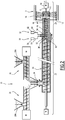
- FIG. 2 On the figure 2 is schematically shown an installation 21 adapted to apply the lining 16 to the base body 10 of a pipe 2 as described above.
- the installation 21 comprises a routing device 22 adapted to convey the mineral filler.
- the installation 21 further comprises a mixing and projection device 24.
- the installation 21 is provided with a first insertion device 26, as well as a second insertion device 28.
- the installation 21 is further provided with a third insertion device 30 and a fourth insertion device 32.
- the routing device 22 is adapted to convey the mineral filler and comprises an enclosure 33 provided with an inlet 34 and an outlet 36.
- the conveying device 22 also constitutes a mixing device adapted to mix the first sub-unit. load component and the second load subcomponent.
- the routing device 22 is a screw conveyor.
- the first input device 26 is adapted to introduce the first load subcomponent into the input 34.
- the second input device 28 is adapted to introduce the second load subcomponent into the input 34.
- the first feeder 26 is a screw feeder and has an inlet reservoir 26A containing the first load subcomponent.
- the second introducer 28 is a screw feeder, and has an inlet reservoir 28A containing the second load subcomponent.
- the mixing and projection device 24 comprises a charge inlet 40, which is disposed downstream of the outlet 36, and an outlet in the form of a projection head 42.
- the mixing and projection device 24 is provided with a housing 44 forming a mixing chamber 46 extending from the load inlet 40 to the spray head 42.
- the mixing and throwing device 24 is also provided with a conveying and mixing screw 48 arranged in the mixing chamber 46.
- the mixing and projecting device 24 defines a central axis YY, which is the central axis of the chamber 46.
- the mixing and projection device 24 also defines a transport direction T directed parallel to the axis YY and directed from the charge inlet 40 to the projection head 42.
- the mixing and projection device 24 is provided with means for rotating the projection head 42 and the transport and mixing screw 48 relative to the casing 44, in the form of a motor 50.
- the projection head 42 and the transport and mixing screw 48 are integral in rotation.
- the projection head 42 and the screw 48 are driven by the same motor 50.
- the third input device 30 is adapted to introduce the first subcomponent of the organic binder into the feedstock.
- the third insertion device 30 comprises an introduction channel 52 opening into the mixing chamber 46.
- the introduction channel 52 opens into the mixing chamber 46 at a location which is situated downstream of the inlet 40, considering the transport direction T.
- This introduction channel 52 is arranged radially with respect to the central axis YY, so that the first subcomponent of the binder is introduced radially into the mixing chamber 46.
- the third input device 30 further comprises a line 54 and a metering device 56.
- the metering device 56 is connected via the line 54 to the introduction channel 52.
- the metering device 56 comprises a reservoir containing the first sub-unit. component of organic binder.
- the fourth introducer 32 includes an introduction channel 58 opening into the mixing chamber 46.
- the introduction channel 58 opens into the mixing chamber 46 at a location which is located downstream of the location where the channel 52 introduces into the mixing chamber 46, considering the transport direction T.
- the fourth feed device 32 further comprises a line 60 and a metering device 62.
- the metering device 62 is connected via the line 60 to the introduction channel 58. Also, the metering device 62 comprises a reservoir containing the second sub-unit. component of organic binder.
- the introduction channel 52 and the pipe 54 are separated along their entire length from the introduction channel 58 and the pipe 60.
- the introduction devices 30, 32 are adapted to introduce the two sub-components of the organic binder separately from one another into the mixing chamber 46.
- the introduction channel 58 opens into the mixing chamber 46 spaced from the introduction channel 52.
- the mixture of epoxide and hardener, in the case of a binder consisting of a polyepoxide resin, or the mixture of polyol and isocyanate in the case of a binder consisting of a polyurethane resin, is thus carried out exclusively in the mixing chamber 46 and not upstream of it. As a result, only the mixing chamber 46 must be cleaned when the plant is shut down and little organic binder is lost.
- the projection head 42 has a particular design.
- the Figures 3 and 4 show a first embodiment of this head 42.
- the projection head 42 comprises a base body 70.
- the base body 70 is for example in the form of hollow cylinder and extends along a central axis AA head.
- the base body 70 has an envelope surface 71.
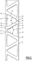
- the projection head 42 has a multitude of projection windows 72 formed in the base body 70. In this case, the projection head 42 has six projection windows 72 Each projection window 72 is a radially through opening of the base body 70 with respect to the central head axis AA.
- Each projection window 72 has a substantially triangular shape with rounded corners.
- Each projection window 72 has three sides, C1, C2, C3. In each case, two sides C1-C2, C2-C3 and C3-C1 are connected by an arcuate part A1, A2, A3.
- Each projection window 72 comprises a wide axial portion 74 and a thin axial portion 76.
- the wide axial portion 74 is, with respect to the axis AA, circumferentially wider than the thin axial portion 76.
- the projection windows 72 are disposed about the central axis A-A so that the wide axial portions 74 and the thin axial portions 76 alternate in the circumferential direction about the central head axis A-A.
- Each projection window 72 thus forms a base constituted by the wide axial portion 74, and a vertex constituted by the thin axial portion 76.
- the sides C1, C2 associated with the vertex form a vertex angle ⁇ between them. This angle ⁇ is between 5 ° and 60 °. In the example shown on the figure 5 the vertex angle ⁇ is 60 °, and the projection windows 72 have an equilateral triangle shape.
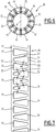
- the Figures 6 and 7 show a second embodiment of a projection head 72.
- the difference with respect to the first embodiment is the number of projection windows 72, which are in this case twelve.
- the vertex angle ⁇ is 20 ° and the projection windows 72 have a general isosceles triangle shape.
- the Figures 8 and 9 show a third embodiment of a projection head 42.
- the only difference with respect to the second embodiment is the vertex angle ⁇ which is here 10 °.
- projection windows 72 have at least two non-parallel sides.
- each projection window 72 may also have a general quadrilateral shape, for example a trapezium shape.
- the first load subcomponent and the second load subcomponent are introduced separately into the inlet 34 of the enclosure 33.
- the two load subcomponents are mixed and conveyed by the device. routing 22 to the outlet 36.
- a homogeneous inorganic filler is obtained at the outlet 36.
- the mineral filler is then introduced into the inlet 40 of the mixing and projection device 24 and is conveyed by the screw 48 in the transport direction T, the screw 48 and the projection head 42 being rotated by the motor 50 .
- the first subcomponent of the organic binder and the second subcomponent of the organic binder are introduced radially with respect to the transport direction T in the inorganic filler, inside the mixing chamber 46.
- This introduction of the first subcomponent of the organic binder in the feed is carried out separately from the introduction of the second subcomponent of the organic binder into the feed.
- the subcomponents of the organic binder and the inorganic filler sub-components are mixed by the screw 48 in the mixing chamber 46 and form a homogeneous resin mortar which is conveyed into the spray head 42.
- head 42 being rotated by the motor 50, the resin mortar is then projected onto the inner surface of the pipe 2 through the projection windows 72.
- the pipe 2 is rotated about its axis XX in a direction of rotation identical to that of the projection head but at a rotation speed lower than that of the projection head, and the projection head 42 is moved axially inside and along the pipe 2.
- the speed of rotation of the pipe 2 about its axis XX is increased in order to smooth the free surface of the resin mortar coating 16.
- the acceleration produced when raising the speed of rotation of the pipe is between 50 and 100 times the normal acceleration of gravity.
- the resin mortar according to the invention may also comprise reinforcing fibers of organic, mineral or metal type, and in a proportion of between 0.5% and 10% by weight relative to the weight of the organic binder.
- the reinforcing fibers are then mixed with the mineral filler before introduction thereof into the conveyor device 22.
- At least one of the insertion channels 52, 58 is arranged in a direction having a radial component or a component perpendicular to the transport direction T, but which is not strictly radial or perpendicular.
- the introduction of the first and / or second subcomponent of the organic binder is carried out in a direction having a component perpendicular to the transport direction T.
- the mineral filler may comprise a single load subcomponent, in particular a sand having a particle size of less than 4 mm.
- the first load subcomponent or the sole load subcomponent has a particle size of between 10 ⁇ m and 1 mm and consists of dry siliceous sand or dry silico-calcareous sand.
- the weight ratio between the inorganic filler and the organic binder is between 4/1 and 7.5 / 1.
- the weight ratio between the inorganic filler and the organic binder is then between 1.5 / 1 and 4/1 and preferably between 2/1 and 3/1.
Landscapes
- Engineering & Computer Science (AREA)
- Mechanical Engineering (AREA)
- Chemical & Material Sciences (AREA)
- General Engineering & Computer Science (AREA)
- Ceramic Engineering (AREA)
- Structural Engineering (AREA)
- Organic Chemistry (AREA)
- Materials Engineering (AREA)
- Chemical Kinetics & Catalysis (AREA)
- Life Sciences & Earth Sciences (AREA)
- Wood Science & Technology (AREA)
- Application Of Or Painting With Fluid Materials (AREA)
- Excavating Of Shafts Or Tunnels (AREA)
- Rigid Pipes And Flexible Pipes (AREA)
- Compositions Of Macromolecular Compounds (AREA)
Description
- La présente invention concerne un procédé de revêtement de l'intérieur d'un élément de canalisation, s'étendant suivant un axe central (X-X) et comprenant :
- un corps de base en métal, définissant une surface extérieure de corps de base et une surface intérieure de corps de base, et
- un revêtement intérieur appliqué sur la surface intérieure de corps de base.
- On connaît dans l'état de la technique des tuyaux de transport d'eaux usées.
- Ces tuyaux comprennent un corps de base en métal sur la surface intérieure duquel est appliqué un revêtement intérieur apte à résister à des eaux ayant un pH compris entre 4 et 13. Les revêtements généralement utilisés comprennent un mortier de ciment. Ces mortiers hydrauliques risquent d'être altérés, notamment lorsque les tuyaux véhiculent des eaux agressives. Les document
JPH0568918A DE3429881A dévoilent chacun un procédé de revêtement de l'intérieur d'une canalisation utilisant un mortier de résine. - L'invention a pour but d'améliorer la durabilité et la résistance à l'abrasion du revêtement intérieur des éléments de canalisation, tels que les tuyaux ou raccords, destinés au transport des eaux usées et effluents.
- A cet effet, l'invention a pour objet un procédé de revêtement de l'intérieur d'un élément de canalisation selon les caractéristiques de la revendication 1. Les modes avantageux de réalisation de l'invention font l'objet des revendications dépendantes 2 à 22.
- Selon des premiers modes de réalisation particuliers de l'invention, l'élément de canalisation comporte l'une ou plusieurs des caractéristiques suivantes :
- le corps de base est en fonte, en particulier en fonte à graphite sphéroïdal ;
- la charge minérale comprend au moins un premier sous-composant de charge, et est notamment constituée de ce premier sous-composant de charge ;
- la charge minérale est constituée du premier sous-composant de charge et d'un second sous-composant de charge, ces deux sous-composants de charge ayant des granulométries différentes ;
- le premier sous-composant de charge a une granulométrie inférieure à 4 mm, notamment comprise entre 10 µm et 1 mm ; et
- le second sous-composant de charge a une granulométrie inférieure à 0,4 mm ;
- le premier sous-composant de charge constitue entre 60% et 90% en poids de la charge minérale, et le second sous-composant de charge constitue entre 40% et 10% en poids de la charge minérale ;
- la charge minérale comprend du sable siliceux sec ou silico-calcaire sec, et notamment au moins l'un des sous-composants de charge est constitué de sable siliceux sec ou silico-calcaire sec ;
- le liant organique comprend et est notamment constitué d'une résine polyépoxyde ou polyuréthane ;
- le liant organique comprend et est notamment constitué d'une résine polyépoxyde, notamment sans solvant, et la résine polyépoxyde est constituée d'un sous-composant époxyde et d'un sous-composant durcisseur ;
- le rapport en poids entre le sous-composant époxyde et le sous-composant durcisseur, à savoir époxyde/durcisseur est compris entre 100/30 et 100/60 ;
- le liant organique comprend et est notamment constitué d'une résine polyuréthane qui est constituée d'un polyol et d'un isocyanate, notamment avec un rapport en poids entre le polyol et l'isocyanate qui est compris entre 100/70 et 100/100 ;
- le rapport en poids entre la charge minérale et le liant organique est compris entre 4/1 et 7,5/1 ;
- le rapport en poids entre la charge minérale et le liant organique est compris entre 1,5/1 et 4/1 et de préférence entre 2/1 et 3/1 ;
- le mortier de résine est constitué d'une charge minérale et d'un liant organique ;
- le mortier de résine comporte des fibres de renforcement dans une proportion comprise entre 0,5% et 10% en poids par rapport au liant organique ;
- une butée adaptée pour s'opposer à un écoulement axial du mortier de résine disposé sur la surface intérieure ;
- la butée comprend un cordon annulaire disposé sur la surface intérieure, notamment un cordon de colle durcie ;
- le revêtement intérieur a une épaisseur de paroi comprise entre 2 mm et 4 mm, notamment sur toute son étendue.
- Selon d'autres modes de réalisation particuliers, le procédé selon l'invention comporte l'une ou plusieurs des caractéristiques suivantes :
- mélanger un premier sous-composant du liant organique et un second sous-composant du liant organique en formant le liant organique ;
- introduire le premier sous-composant du liant organique dans la charge minérale séparément de l'introduction du deuxième sous-composant du liant organique dans la charge minérale, avant leur mélange ;
- mélanger un premier sous-composant de charge et un second sous-composant de charge en obtenant la charge minérale.
- Finalement, une installation adaptée pour le revêtement d'un élément de canalisations est présentée, l'installation comprenant une tête de projection ayant un corps de base en forme de cylindre creux, notamment à section circulaire, et s'étendant selon un axe de tête, caractérisée en ce que la tête de projection comporte au moins une fenêtre de projection ayant deux côtés non parallèles.
- L'installation peut comporter les caractéristiques suivantes :
- la ou chaque fenêtre de projection a une forme générale de triangle ou de quadrilatère ;
- la tête de projection comporte au moins deux fenêtres de projection, chaque fenêtre de projection ayant une portion large et une portion mince et les fenêtres de projection étant disposées de telle sorte que les portions minces et larges alternent selon la direction circonférentielle de la tête de projection ;
- la ou chaque fenêtre de projection a une forme générale de triangle isocèle ou équilatéral ;
- un dispositif de mélange adapté pour mélanger un premier sous-composant de charge et un second sous-composant de charge afin de former la charge minérale ;
- un dispositif d'introduction de liant adapté pour introduire le liant organique dans la charge minérale, le dispositif d'introduction de liant comportant un dispositif d'introduction d'un premier sous-composant du liant organique et un dispositif d'introduction d'un second sous-composant du liant organique ; et
- le dispositif d'introduction du premier sous-composant du liant organique et le dispositif d'introduction du second sous-composant du liant organique sont adaptés pour introduire le premier sous-composant du liant organique et le second sous-composant du liant organique séparément l'un de l'autre ; et
- le dispositif d'introduction de liant est adapté pour introduire le liant organique dans la charge minérale suivant une direction ayant une composante perpendiculaire au sens de transport (T) de la charge, et notamment suivant une direction perpendiculaire à ce sens de transport (T).
- L'invention sera mieux comprise à la lecture de la description qui va suivre, donnée uniquement à titre d'exemple et faite en se référant aux dessins annexés, sur lesquels :
- la
Figure 1 est une vue en coupe longitudinale d'un élément de canalisation ou tuyau obtenu par le procédé selon l'invention; - la
Figure 2 est une vue schématique d'une installation de revêtement d'un tuyau selon l'invention ; - la
Figure 3 est une vue axiale de la tête de projection de l'installation de laFigure 2 ; - la
Figure 4 est une vue en coupe transversale de la tête de projection selon un premier mode de réalisation ; - la
Figure 5 est une vue développée de la surface enveloppante de la tête de projection de laFigure 4 ; - les
Figures 6 et 7 sont des vues analogues à celles desFigures 4 et5 d'un second mode de réalisation de la tête de projection ; et - les
Figures 8 et 9 sont des vues analogues à celles desFigures 4 et5 d'un troisième mode de réalisation de la tête de projection. - Sur la
Figure 1 est représenté un tuyau obtenu par le procédé l'invention, désigné par la référence générale 2. - Ce tuyau 2 s'étend selon un axe central X-X. Dans ce qui suit et sauf indication contraire, les termes « axialement », « radialement » et « circonférentiellement » seront utilisés par rapport à l'axe central X-X.
- Le tuyau 2 comporte un bout uni 4, un bout à emboîtement 6 et une partie intermédiaire 8 s'étendant entre le bout uni 4 et le bout à emboîtement 6.
- Le tuyau 2 est muni d'un corps de base 10, fabriqué par exemple en fonte, et notamment en fonte à graphite sphéroïdal. Ce corps de base 10 définit une surface extérieure 12 de corps de base et une surface intérieure 14 de corps de base.
- La surface extérieure 12 est revêtue d'un revêtement extérieur anticorrosion non représenté, par exemple à base de zinc.
- Le tuyau 2 comporte en outre un revêtement intérieur 16 appliqué sur la surface intérieure 14 de la partie intermédiaire 8 et du bout uni 4. Le bout à emboîtement 6 est dépourvu du revêtement intérieur 16.
- Le revêtement intérieur 16 a de préférence une épaisseur de paroi e comprise entre 2 mm et 4 mm, notamment sur toute son étendue.
- Le revêtement intérieur 16 est en une matière permettant au tuyau 2 de transporter des eaux usées ayant un pH qui est compris entre 4 et 13 et qui peut ponctuellement être inférieur à 4.
- A cet effet, le revêtement intérieur 16 comprend un mortier de résine et est notamment constitué de ce mortier de résine. Ce mortier de résine est dépourvu de ciment minéral et d'eau.
- Le tuyau 2 comprend en outre une première 18 et une seconde 20 butées. En l'occurrence, chaque butée 18, 20 comprend un cordon annulaire disposé sur la surface intérieure 14, et de préférence un cordon de polymère formé par exemple de colle durcie. La première butée 18 est disposée à l'extrémité axiale du bout uni 4, et la seconde butée 20 est disposée à l'extrémité axiale de la partie intermédiaire 8 et est disposée adjacente au bout à emboîtement 6. Lors de l'application du mortier de résine à l'état liquide ou visqueux sur la surface intérieure 14 du tuyau 2, la première butée 18 s'oppose à l'écoulement du mortier de résine en dehors du bout uni 4 tandis que la seconde butée 20 empêche l'écoulement du mortier de résine vers la surface intérieure du bout à emboîtement 6.
- De préférence, la hauteur radiale h de chaque butée 18 ,20 est égale ou supérieure à l'épaisseur de paroi e du revêtement intérieur 16, et ceci sur toute la longueur circonférentielle de la butée.
- Le mortier de résine du revêtement intérieur 16 a une composition spécifique afin d'être facile à appliquer tout en résistant à des effluents agressifs. Le mortier de résine est constitué d'une charge minérale et d'un liant organique.
- La charge minérale comprend un premier sous-composant de charge et un second sous-composant de charge. En particulier, la charge est constituée de ces deux sous-composants.
- Avantageusement, ces deux sous-composants de charge ont des granulométries différentes. De préférence, le premier sous-composant de charge a une granulométrie inférieure à 4 mm, et le second sous-composant de charge a une granulométrie inférieure à 0,4 mm. Le terme granulométrie est utilisé en application de la norme française XP P
18-545 - Par ailleurs, le premier sous-composant de charge constitue entre 60% et 90% en poids de la charge minérale, tandis que le second sous-composant de charge constitue entre 40% et 10% en poids de la charge minérale.
- La charge minérale comprend de préférence du sable siliceux sec ou silico-calcaire sec. Au moins l'un des deux sous-composants de charge est constitué de sable siliceux sec ou silico-calcaire sec. De préférence, chacun des deux sous-composants de charge est constitué d'un tel sable.
- Le liant organique comprend avantageusement une résine polyépoxyde, notamment sans solvant, ou est constitué d'une telle résine polyépoxyde. Cette résine polyépoxyde est constituée d'un sous-composant époxyde et d'un sous-composant durcisseur. Avantageusement, le sous-composant époxyde et le sous-composant durcisseur ont un rapport en poids qui est compris entre 100/30 et 100/60, et de préférence entre 100/40 et 100/55.
- Alternativement, le liant organique comprend une résine polyuréthane, ou est constitué d'une telle résine polyuréthane, qui est constituée d'un sous-composant polyol et d'un sous-composant isocyanate. Le rapport en poids entre le polyol et l'isocyanate est compris entre 100/70 et 100/100, et de préférence entre 100/80 et 100/90.
- Avantageusement, le rapport en poids entre la charge minérale et le liant organique est compris entre 4/1 et 7,5/1.
- Le mortier de résine selon l'invention est particulièrement facile à appliquer sur la surface du corps de base 10, et résiste bien aux effluents agressifs. En particulier, il permet le transport d'effluents ayant un pH compris entre 4 et 13 et pouvant ponctuellement être inférieur à 4.
- Aussi, à l'état non durci, le mortier de résine utilisé dans le procédé selon l'invention est relativement visqueux et a donc peu tendance à s'écouler en dehors du corps de base 10. De ce fait, peu de mortier de résine est perdu lors de son application sur la surface intérieure 14 du tuyau 2.
- Sur la
figure 2 est représentée schématiquement une installation 21 adaptée pour appliquer le revêtement intérieur 16 sur le corps de base 10 d'un tuyau 2 tel que décrit ci-dessus. - L'installation 21 comprend un dispositif d'acheminement 22 adapté pour acheminer la charge minérale. L'installation 21 comprend en outre un dispositif de mélange et de projection 24. Par ailleurs, l'installation 21 est munie d'un premier dispositif d'introduction 26, ainsi que d'un deuxième dispositif d'introduction 28. L'installation 21 est en outre munie d'un troisième dispositif d'introduction 30 et d'un quatrième dispositif d'introduction 32.
- Le dispositif d'acheminement 22 est adapté pour acheminer la charge minérale et comprend une enceinte 33 munie d'une entrée 34 et d'une sortie 36. Le dispositif d'acheminement 22 constitue également un dispositif de mélange adapté pour mélanger le premier sous-composant de charge et le deuxième sous-composant de charge. En l'occurrence, le dispositif d'acheminement 22 est un convoyeur à vis.
- Le premier dispositif d'introduction 26 est adapté pour introduire le premier sous-composant de charge dans l'entrée 34. Le deuxième dispositif d'introduction 28 est adapté pour introduire le deuxième sous-composant de charge dans l'entrée 34.
- Le premier dispositif d'introduction 26 est un doseur à vis et comporte un réservoir d'entrée 26A contenant le premier sous-composant de charge. Le deuxième dispositif d'introduction 28 est un doseur à vis, et comporte un réservoir d'entrée 28A contenant le deuxième sous-composant de charge.
- Le dispositif de mélange et de projection 24 comporte une entrée de charge 40, qui est disposée en aval de la sortie 36, et une sortie sous forme d'une tête de projection 42. Le dispositif de mélange et de projection 24 est muni d'un carter 44 formant une chambre de mélange 46 s'étendant de l'entrée de charge 40 à la tête de projection 42. Le dispositif de mélange et de projection 24 est également muni d'une vis de transport et de mélange 48 disposée dans la chambre de mélange 46.
- Le dispositif de mélange et de projection 24 définit un axe central Y-Y, qui est l'axe central de la chambre 46. Le dispositif de mélange et de projection 24 définit également un sens de transport T dirigé parallèlement à l'axe Y-Y et dirigé de l'entrée de charge 40 vers la tête de projection 42.
- Le dispositif de mélange et de projection 24 est muni de moyens d'entraînement en rotation de la tête de projection 42 et de la vis de transport et de mélange 48 par rapport au carter 44, sous forme d'un moteur 50. D'une manière préférentielle, la tête de projection 42 et la vis de transport et de mélange 48 sont solidaires en rotation. Ainsi, la tête de projection 42 et la vis 48 sont entraînées par le même moteur 50.
- Le troisième dispositif d'introduction 30 est adapté pour introduire le premier sous-composant du liant organique dans la charge.
- Le troisième dispositif d'introduction 30 comporte un canal d'introduction 52 débouchant dans la chambre de mélange 46. Le canal d'introduction 52 débouche dans la chambre de mélange 46 à un emplacement qui est situé en aval de l'entrée 40, en considérant le sens de transport T. Ce canal d'introduction 52 est disposé radialement par rapport à l'axe central Y-Y, de telle sorte que le premier sous-composant du liant est introduit radialement dans la chambre de mélange 46.
- Le troisième dispositif d'introduction 30 comporte par ailleurs une conduite 54 et un dispositif doseur 56. Le dispositif doseur 56 est relié par la conduite 54 au canal d'introduction 52. Aussi, le dispositif doseur 56 comporte un réservoir contenant le premier sous-composant du liant organique.
- Le quatrième dispositif d'introduction 32 comporte un canal d'introduction 58 débouchant dans la chambre de mélange 46. Le canal d'introduction 58 débouche dans la chambre de mélange 46 à un emplacement qui est situé en aval de l'emplacement où le canal d'introduction 52 débouche dans la chambre de mélange 46, en considérant le sens de transport T.
- Le quatrième dispositif d'introduction 32 comporte en outre une conduite 60 et un dispositif doseur 62. Le dispositif doseur 62 est relié par la conduite 60 au canal d'introduction 58. Aussi, le dispositif doseur 62 comporte un réservoir contenant le second sous-composant du liant organique.
- Le canal d'introduction 52 et la conduite 54 sont séparés sur toute leur longueur du canal d'introduction 58 et de la conduite 60.
- D'une manière générale, les dispositifs d'introduction 30, 32 sont adaptés pour introduire les deux sous-composants du liant organique séparément l'un de l'autre dans la chambre de mélange 46. A cet effet, le canal d'introduction 58 débouche dans la chambre de mélange 46 espacé du canal d'introduction 52.
- Le mélange d'époxyde et de durcisseur, dans le cas d'un liant constitué d'une résine polyépoxyde, ou le mélange du polyol et de l'isocyanate dans le cas d'un liant constitué d'une résine polyuréthane, est donc effectué exclusivement dans la chambre de mélange 46 et non pas en amont de celle-ci. En conséquence, seule la chambre de mélange 46 doit être nettoyée lorsque l'installation est mise à l'arrêt et peu de liant organique est donc perdu.
- Afin que le mortier de résine utilisé dans le procédé l'invention puisse être appliqué d'une manière satisfaisante sur la surface intérieure du tuyau, la tête de projection 42 a une conception particulière. Les
figures 3 et 4 montrent un premier mode de réalisation de cette tête 42. - Comme ceci est visible sur les
figures 3 et 4 , la tête de projection 42 comprend un corps de base 70. Le corps de base 70 est par exemple en forme de cylindre creux et s'étend selon un axe central de tête A-A. Le corps de base 70 a une surface d'enveloppe 71. La tête de projection 42 comporte une multitude de fenêtres de projection 72 ménagées dans le corps de base 70. Dans le cas présent, la tête de projection 42 comporte six fenêtres de projection 72. Chaque fenêtre de projection 72 est une ouverture radialement traversante du corps de base 70 par rapport à l'axe central de tête A-A. - La
figure 5 montre la surface d'enveloppe 71 déroulée sur le plan de lafigure 5 . Chaque fenêtre de projection 72 a une forme sensiblement triangulaire à coins arrondis. Chaque fenêtre de projection 72 a trois côtés, C1, C2, C3. A chaque fois, deux côtés C1-C2, C2-C3 et C3-C1 sont reliés par une partie en arc de cercle A1, A2, A3. Chaque fenêtre de projection 72 comporte une portion axiale large 74 et une portion axiale mince 76. La portion axiale large 74 est, par rapport à l'axe A-A, circonférentiellement plus large que la portion axiale mince 76. - Les fenêtres de projection 72 sont disposées autour de l'axe central A-A de telle sorte que les portions axiales larges 74 et les portions axiales minces 76 alternent selon la direction circonférentielle autour de l'axe central de tête A-A.
- Chaque fenêtre de projection 72 forme donc une base, constituée par la portion axiale large 74, et un sommet, constitué par la portion axiale mince 76. Les côtés C1, C2 associés au sommet forment un angle de sommet α entre eux. Cet angle α est compris entre 5° et 60°. Dans l'exemple montré sur la
figure 5 , l'angle de sommet α est de 60°, et les fenêtres de projection 72 ont une forme de triangle équilatéral. - Les
figures 6 et 7 montrent un deuxième mode de réalisation d'une tête de projection 72. La différence par rapport au premier mode de réalisation est le nombre des fenêtres de projection 72, qui sont dans ce cas douze. De plus, l'angle de sommet α est de 20° et les fenêtres de projection 72 ont une forme générale de triangle isocèle. - Les
figures 8 et 9 montrent un troisième mode de réalisation d'une tête de projection 42. La seule différence par rapport au deuxième mode de réalisation est l'angle de sommet α qui est ici de 10°. - De manière générale, les fenêtres de projection 72 ont au moins deux côtés non parallèles. En variante, chaque fenêtre de projection 72 peut également avoir une forme générale quadrilatère, par exemple de trapèze.
- Par la suite sera décrit un procédé d'application d'un revêtement intérieur 16 sur le corps de base 10 d'un tuyau 2 selon l'invention en utilisant l'installation 21 de la
figure 2 .. - Pendant une première étape, le premier sous-composant de charge et le deuxième sous-composant de charge sont introduits séparément dans l'entrée 34 de l'enceinte 33. Les deux sous-composants de charge sont mélangés et acheminés par le dispositif d'acheminement 22 vers la sortie 36. Ainsi, une charge minérale homogène est obtenue au niveau de la sortie 36.
- La charge minérale est alors introduite dans l'entrée 40 du dispositif de mélange et de projection 24 et est acheminée par la vis 48 selon le sens de transport T, la vis 48 et la tête de projection 42 étant entraînées en rotation par le moteur 50.
- Pendant une deuxième étape, le premier sous-composant du liant organique et le deuxième sous-composant du liant organique sont introduits radialement par rapport au sens de transport T dans la charge minérale, à l'intérieur de la chambre de mélange 46. Cette introduction du premier sous-composant du liant organique dans la charge est effectuée séparément de l'introduction du second sous-composant du liant organique dans la charge.
- Pendant une troisième étape, les sous-composants du liant organique et les sous-composants de charge minérale sont mélangés par la vis 48 dans la chambre de mélange 46 et forment un mortier de résine homogène qui est acheminé dans la tête de projection 42. La tête 42 étant entraînée en rotation par le moteur 50, le mortier de résine est alors projeté sur la surface intérieure du tuyau 2 à travers les fenêtres de projection 72.
- Pendant la projection, le tuyau 2 est entraîné en rotation autour de son axe X-X suivant un sens de rotation identique à celui de la tête de projection mais à une vitesse de rotation inférieure à celle de la tête de projection, et la tête de projection 42 est déplacée axialement à l'intérieur et le long du tuyau 2.
- Une fois que toute la partie de la surface intérieure 14 devant être revêtue est couverte par le mortier de résine et tant que celui-ci est à l'état liquide ou visqueux, la vitesse de rotation du tuyau 2 autour se son axe X-X est augmentée afin de lisser la surface libre du revêtement 16 de mortier de résine. L'accélération produite lors de l'élévation de la vitesse de rotation du tuyau est comprise entre 50 et 100 fois l'accélération normale de la pesanteur terrestre.
- En variante, le mortier de résine selon l'invention peut également comprendre des fibres de renforcement de type organiques, minérales ou métalliques, et ce dans une proportion comprise entre 0,5% et 10% en poids par rapport au poids du liant organique. De préférence, les fibres de renforcement sont alors mélangées à la charge minérale avant introduction de celle-ci dans le dispositif d'acheminement 22.
- En variante, au moins l'un des canaux d'introduction 52, 58 est disposé selon une direction ayant une composante radiale ou une composante perpendiculaire au sens de transport T, mais qui n'est pas strictement radiale ou perpendiculaire. Ainsi, l'introduction du premier et/ou du second sous-composant du liant organique est effectué selon une direction ayant une composante perpendiculaire au sens de transport T.
- En variante, la charge minérale peut comprendre un seul sous-composant de charge, notamment un sable de granulométrie inférieure à 4mm.
- On notera que, de préférence, le premier sous-composant de charge ou l'unique sous-composant de charge a une granulométrie comprise entre 10 µm et 1 mm et est constitué de sable siliceux sec ou silico-calcaire sec.
- Dans l'exemple donné ci-dessus où la charge minérale est constituée de deux sables de granulométries distinctes, le rapport en poids entre la charge minérale et le liant organique est compris entre 4/1 et 7,5/1. Cependant, lorsque la charge est constituée d'un seul sable de granulométrie comprise entre 10 µm et 1 mm, le rapport en poids entre la charge minérale et le liant organique est alors compris entre 1,5/1 et 4/1 et de préférence entre 2/1 et 3/1.
Claims (22)
- Procédé de revêtement de l'intérieur d'un élément de canalisation, l'élément de canalisation s'étendant suivant un axe central (X-X) et comprenant un corps de base (10) en métal, définissant une surface extérieure (12) de corps de base et une surface intérieure (14) de corps de base, de manière à former un revêtement intérieur (16) appliqué sur la surface intérieure (14) de corps de base, le revêtement intérieur (16) étant constitué d'un mortier de résine et comprenant une charge minérale et un liant organique, caractérisé en ce que le procédé comprend les étapes suivantes :a) acheminement de la charge minérale, le cas échéant mélangée à des fibres de renforcement, selon un sens de transport (T) et introduction du liant organique ou de premier et second sous-composants du liant organique dans la charge suivant une direction ayant une composante perpendiculaire au sens de transport (T), et notamment suivant une direction perpendiculaire à ce sens de transport (T),b) mélange du liant organique et de la charge minérale, et le cas échéant des fibres de renforcement, en formant un mortier de résine,c) projection du mortier de résine sur la surface intérieure (14) du corps de base (10) de l'élément de canalisation.
- Procédé de revêtement selon la revendication 1, caractérisé en ce que le corps de base (10) est en fonte, en particulier en fonte à graphite sphéroïdal.
- Procédé de revêtement selon l'une quelconque des revendications 1 ou 2, caractérisé en ce que la charge minérale comprend au moins un premier sous-composant de charge, et est notamment constituée de ce premier sous-composant de charge.
- Procédé de revêtement selon la revendication 3, caractérisé en ce que la charge minérale est constituée du premier sous-composant de charge et d'un second sous-composant de charge, ces deux sous-composants de charge ayant des granulométries différentes.
- Procédé de revêtement selon la revendication 3 ou 4, caractérisé en ce que le premier sous-composant de charge a une granulométrie inférieure à 4 mm, notamment comprise entre 10 µm et 1 mm.
- Procédé de revêtement selon au moins la revendication 4, caractérisé en ce que le premier sous-composant de charge constitue entre 60% et 90% en poids de la charge minérale, et le second sous-composant de charge constitue entre 40% et 10% en poids de la charge minérale.
- Procédé de revêtement selon l'une quelconque des revendications 1 à 6, caractérisé en ce que la charge minérale comprend du sable siliceux sec ou silico-calcaire sec, et notamment au moins l'un des sous-composants de charge est constitué de sable siliceux sec ou silico-calcaire sec.
- Procédé de revêtement selon l'une quelconque des revendications 1 à 7, caractérisé en ce que le liant organique comprend et est notamment constitué d'une résine polyépoxyde ou polyuréthane.
- Procédé de revêtement selon la revendication 8, caractérisé en ce que le liant organique comprend et est notamment constitué d'une résine polyépoxyde, notamment sans solvant, et en ce que la résine polyépoxyde est constituée d'un sous-composant époxyde et d'un sous-composant durcisseur.
- Procédé de revêtement selon la revendication 9, caractérisé en ce que le rapport en poids entre le sous-composant époxyde et le sous-composant durcisseur, à savoir époxyde/durcisseur est compris entre 100/30 et 100/60.
- Procédé de revêtement selon la revendication 8, caractérisé en ce que le liant organique comprend et est notamment constitué d'une résine polyuréthane qui est constituée d'un polyol et d'un isocyanate, notamment avec un rapport en poids entre le polyol et l'isocyanate qui est compris entre 100/70 et 100/100.
- Procédé de revêtement selon l'une quelconque des revendications précédentes, caractérisé en ce que le rapport en poids entre la charge minérale et le liant organique est compris entre 4/1 et 7,5/1, ou est compris entre 1,5/1 et 4/1 et de préférence entre 2/1 et 3/1.
- Procédé de revêtement selon l'une quelconque des revendications précédentes, caractérisé en ce que le mortier de résine est constitué d'une charge minérale et d'un liant organique.
- Procédé de revêtement selon l'une quelconque des revendications 1 à 12, caractérisé en ce que le mortier de résine comporte des fibres de renforcement dans une proportion comprise entre 0,5% et 10% en poids par rapport au liant organique.
- Procédé de revêtement selon l'une quelconque des revendications précédentes, caractérisé en ce qu'il comprend une butée (18, 20) adaptée pour s'opposer à un écoulement axial du mortier de résine disposé sur la surface intérieure (14).
- Procédé de revêtement selon la revendication 15, caractérisé en ce que la butée (18, 20) comprend un cordon annulaire disposé sur la surface intérieure, notamment un cordon de colle durcie.
- Procédé de revêtement selon l'une quelconque des revendications précédentes, caractérisé en ce que le revêtement intérieur (16) a une épaisseur de paroi (e) comprise entre 2 mm et 4 mm, notamment sur toute son étendue.
- Procédé de revêtement selon l'une quelconque des revendications précédentes, comprenant en outre l'étape d'introduire le premier sous-composant du liant organique dans la charge minérale séparément de l'introduction du deuxième sous-composant du liant organique dans la charge minérale, avant leur mélange.
- Procédé de revêtement selon la revendication 18, comprenant en outre l'étape de mélanger un premier sous-composant de charge et un second sous-composant de charge en obtenant la charge minérale.
- Procédé de revêtement selon l'une quelconque des revendications précédentes, dans lequel l'acheminement de la charge minérale s'effectue, au cours d'une première phase, dans un dispositif d'acheminement (22) formant un convoyeur à vis et comprenant une enceinte (33) munie d'une entrée (34) et d'une sortie (36) et, au cours d'une deuxième phase, dans un dispositif de mélange et de projection (24) comportant une entrée de charge (40) qui est disposée en aval de la sortie (36) du dispositif d'acheminement (22), une sortie sous forme d'une tête de projection (42), une chambre de mélange (46) s'étendant de l'entrée de charge (40) à la tête de projection (42), et une vis de transport et de mélange (48) disposée dans la chambre de mélange (46), l'introduction du liant organique et le mélange avec la charge s'effectuant à l'intérieur de ladite chambre de mélange (46).
- Procédé de revêtement selon la revendication 20, dans lequel la projection du mortier de résine s'effectue au moyen de la tête de projection (42), ladite tête de projection (42) étant entraînée en rotation par des moyens d'entraînement dont est muni le dispositif de mélange et de projection (24).
- Procédé de revêtement selon la revendication 20 ou 21, dans lequel la vis du dispositif d'acheminement (22) est dissociée de la vis de transport et de mélange (48) du dispositif de mélange et de projection (24), chaque vis étant entraînée en rotation par un moteur (M) distinct et celui entraînant la vis de transport et de mélange (48) entraînant également en rotation la tête de projection (42).
Applications Claiming Priority (2)
| Application Number | Priority Date | Filing Date | Title |
|---|---|---|---|
| FR1052510A FR2958367B1 (fr) | 2010-04-02 | 2010-04-02 | Element de canalisation revetu d'un mortier de resine, procede et installation de revetement correspondants |
| PCT/FR2011/050737 WO2011121252A1 (fr) | 2010-04-02 | 2011-04-01 | Elément de canalisation revêtu d'un mortier de résine et procédé correspondant |
Publications (2)
| Publication Number | Publication Date |
|---|---|
| EP2552600A1 EP2552600A1 (fr) | 2013-02-06 |
| EP2552600B1 true EP2552600B1 (fr) | 2019-05-22 |
Family
ID=42732168
Family Applications (1)
| Application Number | Title | Priority Date | Filing Date |
|---|---|---|---|
| EP11719325.0A Active EP2552600B1 (fr) | 2010-04-02 | 2011-04-01 | Procedé de revêtement de l'intérieur d'un elément de canalisation avec un mortier de résine |
Country Status (7)
| Country | Link |
|---|---|
| EP (1) | EP2552600B1 (fr) |
| CN (1) | CN102933313B (fr) |
| BR (1) | BR112012024998B1 (fr) |
| ES (1) | ES2742776T3 (fr) |
| FR (1) | FR2958367B1 (fr) |
| RU (1) | RU2546160C2 (fr) |
| WO (1) | WO2011121252A1 (fr) |
Families Citing this family (5)
| Publication number | Priority date | Publication date | Assignee | Title |
|---|---|---|---|---|
| CN105673956B (zh) * | 2014-11-21 | 2019-04-19 | 湖南振辉管业有限公司 | 一种环保陶瓷涂层球墨铸铁管及其制作方法 |
| CN104482320B (zh) * | 2014-11-21 | 2017-01-18 | 湖南振辉管业有限公司 | 一种多功能球墨铸铁管 |
| US20180224050A1 (en) * | 2017-02-03 | 2018-08-09 | Oleg Tumarkin | Deposition device for well construction |
| DE102018124494A1 (de) * | 2018-10-04 | 2020-04-09 | DEULA-Nienburg GmbH | Rohr und Bewässerungssystem |
| EP3845609A1 (fr) | 2020-01-06 | 2021-07-07 | SUEZ Groupe | Revêtement comprenant une matrice sol-gel pour tuyaux dans un réseau de distribution d'eau et procédé correspondant |
Citations (3)
| Publication number | Priority date | Publication date | Assignee | Title |
|---|---|---|---|---|
| CN88105883A (zh) * | 1988-03-30 | 1988-10-19 | 四川省五通桥盐厂 | 输卤钢管内涂环氧胶泥装置及方法 |
| JPH0568918A (ja) * | 1991-09-11 | 1993-03-23 | Kurimoto Ltd | 管の内面ライニング方法およびその装置 |
| JP2005194124A (ja) * | 2004-01-06 | 2005-07-21 | Nippon Steel Corp | 無機質系樹脂モルタル組成物及び無機質系樹脂モルタル被覆鋼材 |
Family Cites Families (17)
| Publication number | Priority date | Publication date | Assignee | Title |
|---|---|---|---|---|
| FR1229741A (fr) * | 1959-01-19 | 1960-09-09 | Procédé d'étanchéisation aux produits pétroliers et chimiques applicable aux canalisations, tuyauteries et réservoirs en béton | |
| FR2215126A5 (fr) * | 1972-12-21 | 1974-08-19 | Saint Gobain Techn Nouvelles | |
| DE2640075A1 (de) * | 1976-09-06 | 1978-03-16 | Lechler Chemie Gmbh | Verfahren und stoffmischung zur herstellung von rostschutzueberzuegen auf nassen stahlflaechen |
| FR2414952A1 (fr) * | 1978-01-20 | 1979-08-17 | Ligouzat Pierre | Dispositif pour le melange continu de produits solides a l'etat divise et de produits liquides |
| DE3010525C2 (de) * | 1980-03-17 | 1983-03-03 | Mannesmann AG, 4000 Düsseldorf | Verfahren zur Herstellung einer korrosionsbeständigen Schutzschicht auf der Innenfläche von Stahlrohren |
| CA1163877A (fr) * | 1980-06-06 | 1984-03-20 | Martin Rohn | Enduit protecteur contre les dommages mecaniques aux canalisations |
| DE3041973A1 (de) * | 1980-11-04 | 1982-08-19 | Mannesmann AG, 4000 Düsseldorf | Verfahren zur herstellung von zementmoertel-auskleidungen in metallrohren mit hoher bestaendigkeit gegen rissbildung bei mechanischer beanspruchung |
| DE3429881A1 (de) * | 1984-08-14 | 1986-02-20 | E. Heitkamp Rohrbau GmbH, 4690 Herne | Verfahren und vorrichtung zur herstellung eines innenschutzes von abwasserrohren, z.b. betonrohren |
| US5321062A (en) * | 1992-10-20 | 1994-06-14 | Halliburton Company | Substituted alkoxy benzene and use thereof as wetting aid for polyepoxide resins |
| JPH07224234A (ja) * | 1994-02-08 | 1995-08-22 | Nippon Paint Co Ltd | 鋳鉄管内面用エポキシ粉体塗料 |
| DE19858554A1 (de) * | 1998-12-18 | 2000-06-21 | Sueddeutsche Kalkstickstoff | Selbstvernetzende Polyurethan-Polymer-Hybrid-Dispersion |
| CN2438902Y (zh) * | 1999-11-09 | 2001-07-11 | 新兴铸管股份有限公司 | 免烧陶瓷内衬球墨铸铁管 |
| CN1171029C (zh) * | 2000-09-01 | 2004-10-13 | 复旦大学 | 互穿网络型陶瓷基复合内衬的钢管的制备方法 |
| RU27850U1 (ru) * | 2002-04-22 | 2003-02-20 | Акционерное общество закрытого типа "Прогресс" | Труба с многофункциональным слоистым покрытием |
| US20070065615A1 (en) * | 2005-09-16 | 2007-03-22 | Odle Roy R | Annular or tubular shaped articles of novel polymer blends |
| DE102005054153B4 (de) * | 2005-11-09 | 2008-07-03 | F. Fiedler Baugesellschaft Mbh | Vorrichtung zum kontinuierlichen und dosierten Mischen sowie Austragen hochgefüllter Polyurethansysteme |
| RU57864U1 (ru) * | 2006-05-31 | 2006-10-27 | Владимир Степанович Винарский | Композитная труба |
-
2010
- 2010-04-02 FR FR1052510A patent/FR2958367B1/fr not_active Expired - Fee Related
-
2011
- 2011-04-01 BR BR112012024998-3A patent/BR112012024998B1/pt active IP Right Grant
- 2011-04-01 CN CN201180023863.5A patent/CN102933313B/zh active Active
- 2011-04-01 RU RU2012146724/05A patent/RU2546160C2/ru active
- 2011-04-01 EP EP11719325.0A patent/EP2552600B1/fr active Active
- 2011-04-01 WO PCT/FR2011/050737 patent/WO2011121252A1/fr not_active Ceased
- 2011-04-01 ES ES11719325T patent/ES2742776T3/es active Active
Patent Citations (3)
| Publication number | Priority date | Publication date | Assignee | Title |
|---|---|---|---|---|
| CN88105883A (zh) * | 1988-03-30 | 1988-10-19 | 四川省五通桥盐厂 | 输卤钢管内涂环氧胶泥装置及方法 |
| JPH0568918A (ja) * | 1991-09-11 | 1993-03-23 | Kurimoto Ltd | 管の内面ライニング方法およびその装置 |
| JP2005194124A (ja) * | 2004-01-06 | 2005-07-21 | Nippon Steel Corp | 無機質系樹脂モルタル組成物及び無機質系樹脂モルタル被覆鋼材 |
Also Published As
| Publication number | Publication date |
|---|---|
| RU2546160C2 (ru) | 2015-04-10 |
| WO2011121252A1 (fr) | 2011-10-06 |
| BR112012024998A2 (pt) | 2021-07-13 |
| BR112012024998B1 (pt) | 2022-04-12 |
| CN102933313B (zh) | 2017-06-09 |
| CN102933313A (zh) | 2013-02-13 |
| EP2552600A1 (fr) | 2013-02-06 |
| FR2958367B1 (fr) | 2012-07-27 |
| ES2742776T3 (es) | 2020-02-17 |
| FR2958367A1 (fr) | 2011-10-07 |
| RU2012146724A (ru) | 2014-05-10 |
Similar Documents
| Publication | Publication Date | Title |
|---|---|---|
| EP2552601B1 (fr) | Installation de revêtement intérieur d'un élément de canalisation et utilisation correspondante | |
| WO2011121252A1 (fr) | Elément de canalisation revêtu d'un mortier de résine et procédé correspondant | |
| EP1899638B1 (fr) | Pièce de raccordement de conduites comportant une chemise interne, procede de revetement et procede d'assemblage | |
| US5301984A (en) | Wear resistant pipe elbow | |
| WO1998044236A1 (fr) | Joint filete pour tubes | |
| EP2118550A2 (fr) | Tuyau revêtu d'élastomère, résistant à l'abrasion, et procédé de fabrication | |
| CA2567385C (fr) | Centrale de dosage en beton | |
| FR2958203A1 (fr) | Installation de revetement interieur d'un element de canalisation et utilisation correspondante | |
| CA2274016C (fr) | Produit de revetement interne d'un element de canalisation, procede et machine pour sa mise en oeuvre, et element de canalisation revetu par ce produit | |
| CA2891814C (fr) | Jonction tubulaire | |
| US5294059A (en) | Device for directing the flow of an atomized slurry | |
| EP4400754B1 (fr) | Tuyau, jonction tubulaire et procédé de fabrication correspondants | |
| CA2802659A1 (fr) | Procede de protection d'un composant de machine hydraulique contre l'erosion | |
| FR2511752A1 (fr) | Coude pour circuits de tuyauteries notamment pour le transport pneumatique de poudres ou granules | |
| CN217130683U (zh) | 一种物料输送弯管 | |
| FR2876599A1 (fr) | Dispositif pour creer un jet fluide orbital pur ou charge de particules notamment abrasives | |
| FR2547892A1 (fr) | Procede de fabrication d'un troncon de tuyau ou de tube et ce troncon | |
| JP2005111305A (ja) | 既設配管内面塗布装置及び塗布方法 | |
| JPH04337193A (ja) | 管体の補強方法および補強部材 | |
| OA17411A (fr) | Jonction tubulaire. |
Legal Events
| Date | Code | Title | Description |
|---|---|---|---|
| PUAI | Public reference made under article 153(3) epc to a published international application that has entered the european phase |
Free format text: ORIGINAL CODE: 0009012 |
|
| 17P | Request for examination filed |
Effective date: 20120928 |
|
| AK | Designated contracting states |
Kind code of ref document: A1 Designated state(s): AL AT BE BG CH CY CZ DE DK EE ES FI FR GB GR HR HU IE IS IT LI LT LU LV MC MK MT NL NO PL PT RO RS SE SI SK SM TR |
|
| DAX | Request for extension of the european patent (deleted) | ||
| RAP1 | Party data changed (applicant data changed or rights of an application transferred) |
Owner name: SAINT-GOBAIN PAM |
|
| STAA | Information on the status of an ep patent application or granted ep patent |
Free format text: STATUS: EXAMINATION IS IN PROGRESS |
|
| 17Q | First examination report despatched |
Effective date: 20161115 |
|
| RIC1 | Information provided on ipc code assigned before grant |
Ipc: B29C 47/10 20060101ALI20181008BHEP Ipc: B29C 47/36 20060101ALI20181008BHEP Ipc: B29K 105/16 20060101ALI20181008BHEP Ipc: B29K 105/00 20060101ALI20181008BHEP Ipc: B28B 19/00 20060101ALI20181008BHEP Ipc: B29C 67/24 20060101ALI20181008BHEP Ipc: C04B 26/16 20060101ALI20181008BHEP Ipc: B05C 7/02 20060101AFI20181008BHEP Ipc: F16L 58/06 20060101ALI20181008BHEP Ipc: B05B 13/06 20060101ALI20181008BHEP Ipc: F16L 57/06 20060101ALI20181008BHEP Ipc: F16L 9/04 20060101ALI20181008BHEP Ipc: B05D 1/02 20060101ALI20181008BHEP Ipc: B05D 7/22 20060101ALI20181008BHEP Ipc: B29C 47/00 20060101ALI20181008BHEP Ipc: F16L 9/147 20060101ALI20181008BHEP Ipc: C04B 26/14 20060101ALI20181008BHEP Ipc: F16L 58/10 20060101ALI20181008BHEP Ipc: B29C 47/46 20060101ALI20181008BHEP Ipc: F16L 58/08 20060101ALI20181008BHEP |
|
| GRAP | Despatch of communication of intention to grant a patent |
Free format text: ORIGINAL CODE: EPIDOSNIGR1 |
|
| STAA | Information on the status of an ep patent application or granted ep patent |
Free format text: STATUS: GRANT OF PATENT IS INTENDED |
|
| INTG | Intention to grant announced |
Effective date: 20181123 |
|
| GRAS | Grant fee paid |
Free format text: ORIGINAL CODE: EPIDOSNIGR3 |
|
| GRAA | (expected) grant |
Free format text: ORIGINAL CODE: 0009210 |
|
| STAA | Information on the status of an ep patent application or granted ep patent |
Free format text: STATUS: THE PATENT HAS BEEN GRANTED |
|
| AK | Designated contracting states |
Kind code of ref document: B1 Designated state(s): AL AT BE BG CH CY CZ DE DK EE ES FI FR GB GR HR HU IE IS IT LI LT LU LV MC MK MT NL NO PL PT RO RS SE SI SK SM TR |
|
| REG | Reference to a national code |
Ref country code: GB Ref legal event code: FG4D Free format text: NOT ENGLISH |
|
| REG | Reference to a national code |
Ref country code: CH Ref legal event code: EP |
|
| REG | Reference to a national code |
Ref country code: IE Ref legal event code: FG4D Free format text: LANGUAGE OF EP DOCUMENT: FRENCH |
|
| REG | Reference to a national code |
Ref country code: DE Ref legal event code: R096 Ref document number: 602011059168 Country of ref document: DE |
|
| REG | Reference to a national code |
Ref country code: AT Ref legal event code: REF Ref document number: 1135464 Country of ref document: AT Kind code of ref document: T Effective date: 20190615 |
|
| REG | Reference to a national code |
Ref country code: CH Ref legal event code: NV Representative=s name: MICHELI AND CIE SA, CH |
|
| REG | Reference to a national code |
Ref country code: NL Ref legal event code: MP Effective date: 20190522 |
|
| REG | Reference to a national code |
Ref country code: LT Ref legal event code: MG4D |
|
| PG25 | Lapsed in a contracting state [announced via postgrant information from national office to epo] |
Ref country code: AL Free format text: LAPSE BECAUSE OF FAILURE TO SUBMIT A TRANSLATION OF THE DESCRIPTION OR TO PAY THE FEE WITHIN THE PRESCRIBED TIME-LIMIT Effective date: 20190522 Ref country code: SE Free format text: LAPSE BECAUSE OF FAILURE TO SUBMIT A TRANSLATION OF THE DESCRIPTION OR TO PAY THE FEE WITHIN THE PRESCRIBED TIME-LIMIT Effective date: 20190522 Ref country code: PT Free format text: LAPSE BECAUSE OF FAILURE TO SUBMIT A TRANSLATION OF THE DESCRIPTION OR TO PAY THE FEE WITHIN THE PRESCRIBED TIME-LIMIT Effective date: 20190922 Ref country code: LT Free format text: LAPSE BECAUSE OF FAILURE TO SUBMIT A TRANSLATION OF THE DESCRIPTION OR TO PAY THE FEE WITHIN THE PRESCRIBED TIME-LIMIT Effective date: 20190522 Ref country code: FI Free format text: LAPSE BECAUSE OF FAILURE TO SUBMIT A TRANSLATION OF THE DESCRIPTION OR TO PAY THE FEE WITHIN THE PRESCRIBED TIME-LIMIT Effective date: 20190522 Ref country code: NO Free format text: LAPSE BECAUSE OF FAILURE TO SUBMIT A TRANSLATION OF THE DESCRIPTION OR TO PAY THE FEE WITHIN THE PRESCRIBED TIME-LIMIT Effective date: 20190822 Ref country code: NL Free format text: LAPSE BECAUSE OF FAILURE TO SUBMIT A TRANSLATION OF THE DESCRIPTION OR TO PAY THE FEE WITHIN THE PRESCRIBED TIME-LIMIT Effective date: 20190522 Ref country code: HR Free format text: LAPSE BECAUSE OF FAILURE TO SUBMIT A TRANSLATION OF THE DESCRIPTION OR TO PAY THE FEE WITHIN THE PRESCRIBED TIME-LIMIT Effective date: 20190522 |
|
| PG25 | Lapsed in a contracting state [announced via postgrant information from national office to epo] |
Ref country code: RS Free format text: LAPSE BECAUSE OF FAILURE TO SUBMIT A TRANSLATION OF THE DESCRIPTION OR TO PAY THE FEE WITHIN THE PRESCRIBED TIME-LIMIT Effective date: 20190522 Ref country code: BG Free format text: LAPSE BECAUSE OF FAILURE TO SUBMIT A TRANSLATION OF THE DESCRIPTION OR TO PAY THE FEE WITHIN THE PRESCRIBED TIME-LIMIT Effective date: 20190822 Ref country code: GR Free format text: LAPSE BECAUSE OF FAILURE TO SUBMIT A TRANSLATION OF THE DESCRIPTION OR TO PAY THE FEE WITHIN THE PRESCRIBED TIME-LIMIT Effective date: 20190823 Ref country code: LV Free format text: LAPSE BECAUSE OF FAILURE TO SUBMIT A TRANSLATION OF THE DESCRIPTION OR TO PAY THE FEE WITHIN THE PRESCRIBED TIME-LIMIT Effective date: 20190522 |
|
| PG25 | Lapsed in a contracting state [announced via postgrant information from national office to epo] |
Ref country code: CZ Free format text: LAPSE BECAUSE OF FAILURE TO SUBMIT A TRANSLATION OF THE DESCRIPTION OR TO PAY THE FEE WITHIN THE PRESCRIBED TIME-LIMIT Effective date: 20190522 Ref country code: DK Free format text: LAPSE BECAUSE OF FAILURE TO SUBMIT A TRANSLATION OF THE DESCRIPTION OR TO PAY THE FEE WITHIN THE PRESCRIBED TIME-LIMIT Effective date: 20190522 Ref country code: RO Free format text: LAPSE BECAUSE OF FAILURE TO SUBMIT A TRANSLATION OF THE DESCRIPTION OR TO PAY THE FEE WITHIN THE PRESCRIBED TIME-LIMIT Effective date: 20190522 Ref country code: EE Free format text: LAPSE BECAUSE OF FAILURE TO SUBMIT A TRANSLATION OF THE DESCRIPTION OR TO PAY THE FEE WITHIN THE PRESCRIBED TIME-LIMIT Effective date: 20190522 Ref country code: SK Free format text: LAPSE BECAUSE OF FAILURE TO SUBMIT A TRANSLATION OF THE DESCRIPTION OR TO PAY THE FEE WITHIN THE PRESCRIBED TIME-LIMIT Effective date: 20190522 |
|
| REG | Reference to a national code |
Ref country code: ES Ref legal event code: FG2A Ref document number: 2742776 Country of ref document: ES Kind code of ref document: T3 Effective date: 20200217 |
|
| REG | Reference to a national code |
Ref country code: DE Ref legal event code: R097 Ref document number: 602011059168 Country of ref document: DE |
|
| PG25 | Lapsed in a contracting state [announced via postgrant information from national office to epo] |
Ref country code: SM Free format text: LAPSE BECAUSE OF FAILURE TO SUBMIT A TRANSLATION OF THE DESCRIPTION OR TO PAY THE FEE WITHIN THE PRESCRIBED TIME-LIMIT Effective date: 20190522 |
|
| PLBE | No opposition filed within time limit |
Free format text: ORIGINAL CODE: 0009261 |
|
| STAA | Information on the status of an ep patent application or granted ep patent |
Free format text: STATUS: NO OPPOSITION FILED WITHIN TIME LIMIT |
|
| 26N | No opposition filed |
Effective date: 20200225 |
|
| PG25 | Lapsed in a contracting state [announced via postgrant information from national office to epo] |
Ref country code: PL Free format text: LAPSE BECAUSE OF FAILURE TO SUBMIT A TRANSLATION OF THE DESCRIPTION OR TO PAY THE FEE WITHIN THE PRESCRIBED TIME-LIMIT Effective date: 20190522 |
|
| PG25 | Lapsed in a contracting state [announced via postgrant information from national office to epo] |
Ref country code: SI Free format text: LAPSE BECAUSE OF FAILURE TO SUBMIT A TRANSLATION OF THE DESCRIPTION OR TO PAY THE FEE WITHIN THE PRESCRIBED TIME-LIMIT Effective date: 20190522 |
|
| PG25 | Lapsed in a contracting state [announced via postgrant information from national office to epo] |
Ref country code: MC Free format text: LAPSE BECAUSE OF FAILURE TO SUBMIT A TRANSLATION OF THE DESCRIPTION OR TO PAY THE FEE WITHIN THE PRESCRIBED TIME-LIMIT Effective date: 20190522 |
|
| PG25 | Lapsed in a contracting state [announced via postgrant information from national office to epo] |
Ref country code: LU Free format text: LAPSE BECAUSE OF NON-PAYMENT OF DUE FEES Effective date: 20200401 |
|
| REG | Reference to a national code |
Ref country code: BE Ref legal event code: MM Effective date: 20200430 |
|
| REG | Reference to a national code |
Ref country code: AT Ref legal event code: UEP Ref document number: 1135464 Country of ref document: AT Kind code of ref document: T Effective date: 20190522 |
|
| PG25 | Lapsed in a contracting state [announced via postgrant information from national office to epo] |
Ref country code: BE Free format text: LAPSE BECAUSE OF NON-PAYMENT OF DUE FEES Effective date: 20200430 |
|
| PG25 | Lapsed in a contracting state [announced via postgrant information from national office to epo] |
Ref country code: IE Free format text: LAPSE BECAUSE OF NON-PAYMENT OF DUE FEES Effective date: 20200401 |
|
| PGFP | Annual fee paid to national office [announced via postgrant information from national office to epo] |
Ref country code: IT Payment date: 20210310 Year of fee payment: 11 |
|
| PGFP | Annual fee paid to national office [announced via postgrant information from national office to epo] |
Ref country code: GB Payment date: 20210318 Year of fee payment: 11 Ref country code: TR Payment date: 20210326 Year of fee payment: 11 |
|
| PGFP | Annual fee paid to national office [announced via postgrant information from national office to epo] |
Ref country code: DE Payment date: 20210316 Year of fee payment: 11 |
|
| PGFP | Annual fee paid to national office [announced via postgrant information from national office to epo] |
Ref country code: AT Payment date: 20210325 Year of fee payment: 11 Ref country code: ES Payment date: 20210506 Year of fee payment: 11 Ref country code: CH Payment date: 20210416 Year of fee payment: 11 |
|
| PG25 | Lapsed in a contracting state [announced via postgrant information from national office to epo] |
Ref country code: MT Free format text: LAPSE BECAUSE OF FAILURE TO SUBMIT A TRANSLATION OF THE DESCRIPTION OR TO PAY THE FEE WITHIN THE PRESCRIBED TIME-LIMIT Effective date: 20190522 Ref country code: CY Free format text: LAPSE BECAUSE OF FAILURE TO SUBMIT A TRANSLATION OF THE DESCRIPTION OR TO PAY THE FEE WITHIN THE PRESCRIBED TIME-LIMIT Effective date: 20190522 |
|
| PG25 | Lapsed in a contracting state [announced via postgrant information from national office to epo] |
Ref country code: MK Free format text: LAPSE BECAUSE OF FAILURE TO SUBMIT A TRANSLATION OF THE DESCRIPTION OR TO PAY THE FEE WITHIN THE PRESCRIBED TIME-LIMIT Effective date: 20190522 Ref country code: IS Free format text: LAPSE BECAUSE OF FAILURE TO SUBMIT A TRANSLATION OF THE DESCRIPTION OR TO PAY THE FEE WITHIN THE PRESCRIBED TIME-LIMIT Effective date: 20190922 |
|
| REG | Reference to a national code |
Ref country code: DE Ref legal event code: R119 Ref document number: 602011059168 Country of ref document: DE |
|
| REG | Reference to a national code |
Ref country code: CH Ref legal event code: PL |
|
| REG | Reference to a national code |
Ref country code: AT Ref legal event code: MM01 Ref document number: 1135464 Country of ref document: AT Kind code of ref document: T Effective date: 20220401 |
|
| GBPC | Gb: european patent ceased through non-payment of renewal fee |
Effective date: 20220401 |
|
| PG25 | Lapsed in a contracting state [announced via postgrant information from national office to epo] |
Ref country code: LI Free format text: LAPSE BECAUSE OF NON-PAYMENT OF DUE FEES Effective date: 20220430 Ref country code: GB Free format text: LAPSE BECAUSE OF NON-PAYMENT OF DUE FEES Effective date: 20220401 Ref country code: DE Free format text: LAPSE BECAUSE OF NON-PAYMENT OF DUE FEES Effective date: 20221103 Ref country code: CH Free format text: LAPSE BECAUSE OF NON-PAYMENT OF DUE FEES Effective date: 20220430 Ref country code: AT Free format text: LAPSE BECAUSE OF NON-PAYMENT OF DUE FEES Effective date: 20220401 |
|
| REG | Reference to a national code |
Ref country code: ES Ref legal event code: FD2A Effective date: 20230526 |
|
| PG25 | Lapsed in a contracting state [announced via postgrant information from national office to epo] |
Ref country code: IT Free format text: LAPSE BECAUSE OF NON-PAYMENT OF DUE FEES Effective date: 20220401 |
|
| PG25 | Lapsed in a contracting state [announced via postgrant information from national office to epo] |
Ref country code: ES Free format text: LAPSE BECAUSE OF NON-PAYMENT OF DUE FEES Effective date: 20220402 |
|
| PGFP | Annual fee paid to national office [announced via postgrant information from national office to epo] |
Ref country code: FR Payment date: 20240308 Year of fee payment: 14 |
|
| PG25 | Lapsed in a contracting state [announced via postgrant information from national office to epo] |
Ref country code: TR Free format text: LAPSE BECAUSE OF NON-PAYMENT OF DUE FEES Effective date: 20220401 |
|
| PG25 | Lapsed in a contracting state [announced via postgrant information from national office to epo] |
Ref country code: FR Free format text: LAPSE BECAUSE OF NON-PAYMENT OF DUE FEES Effective date: 20250430 |