EP2552016A1 - Convertisseur abaisseur de fréquence - Google Patents
Convertisseur abaisseur de fréquence Download PDFInfo
- Publication number
- EP2552016A1 EP2552016A1 EP11250679A EP11250679A EP2552016A1 EP 2552016 A1 EP2552016 A1 EP 2552016A1 EP 11250679 A EP11250679 A EP 11250679A EP 11250679 A EP11250679 A EP 11250679A EP 2552016 A1 EP2552016 A1 EP 2552016A1
- Authority
- EP
- European Patent Office
- Prior art keywords
- signal
- local oscillator
- frequency
- band
- converter
- Prior art date
- Legal status (The legal status is an assumption and is not a legal conclusion. Google has not performed a legal analysis and makes no representation as to the accuracy of the status listed.)
- Granted
Links
Images


Classifications
-
- H—ELECTRICITY
- H03—ELECTRONIC CIRCUITRY
- H03D—DEMODULATION OR TRANSFERENCE OF MODULATION FROM ONE CARRIER TO ANOTHER
- H03D7/00—Transference of modulation from one carrier to another, e.g. frequency-changing
- H03D7/16—Multiple-frequency-changing
- H03D7/161—Multiple-frequency-changing all the frequency changers being connected in cascade
- H03D7/163—Multiple-frequency-changing all the frequency changers being connected in cascade the local oscillations of at least two of the frequency changers being derived from a single oscillator
-
- H—ELECTRICITY
- H03—ELECTRONIC CIRCUITRY
- H03D—DEMODULATION OR TRANSFERENCE OF MODULATION FROM ONE CARRIER TO ANOTHER
- H03D7/00—Transference of modulation from one carrier to another, e.g. frequency-changing
- H03D7/16—Multiple-frequency-changing
- H03D7/165—Multiple-frequency-changing at least two frequency changers being located in different paths, e.g. in two paths with carriers in quadrature
-
- H—ELECTRICITY
- H04—ELECTRIC COMMUNICATION TECHNIQUE
- H04B—TRANSMISSION
- H04B1/00—Details of transmission systems, not covered by a single one of groups H04B3/00 - H04B13/00; Details of transmission systems not characterised by the medium used for transmission
- H04B1/005—Details of transmission systems, not covered by a single one of groups H04B3/00 - H04B13/00; Details of transmission systems not characterised by the medium used for transmission adapting radio receivers, transmitters andtransceivers for operation on two or more bands, i.e. frequency ranges
- H04B1/0067—Details of transmission systems, not covered by a single one of groups H04B3/00 - H04B13/00; Details of transmission systems not characterised by the medium used for transmission adapting radio receivers, transmitters andtransceivers for operation on two or more bands, i.e. frequency ranges with one or more circuit blocks in common for different bands
- H04B1/0082—Details of transmission systems, not covered by a single one of groups H04B3/00 - H04B13/00; Details of transmission systems not characterised by the medium used for transmission adapting radio receivers, transmitters andtransceivers for operation on two or more bands, i.e. frequency ranges with one or more circuit blocks in common for different bands with a common local oscillator for more than one band
-
- H—ELECTRICITY
- H04—ELECTRIC COMMUNICATION TECHNIQUE
- H04B—TRANSMISSION
- H04B7/00—Radio transmission systems, i.e. using radiation field
- H04B7/02—Diversity systems; Multi-antenna system, i.e. transmission or reception using multiple antennas
- H04B7/04—Diversity systems; Multi-antenna system, i.e. transmission or reception using multiple antennas using two or more spaced independent antennas
- H04B7/0413—MIMO systems
- H04B7/0456—Selection of precoding matrices or codebooks, e.g. using matrices antenna weighting
- H04B7/046—Selection of precoding matrices or codebooks, e.g. using matrices antenna weighting taking physical layer constraints into account
- H04B7/0469—Selection of precoding matrices or codebooks, e.g. using matrices antenna weighting taking physical layer constraints into account taking special antenna structures, e.g. cross polarized antennas into account
Definitions
- the present disclosure relates to the field of down-converters, and in particular, although not exclusively, to down-converters for down-converting a multiband radio frequency signal using a local oscillator signal.
- each down-conversion process requires a single dielectric resonant oscillator (DRO) to act as a local oscillator.
- DRO dielectric resonant oscillator
- Ka-band which has 3 band groups
- 3 DROs are needed.
- 2 DROs are required for the down-conversion of Ku-band.
- a combined Ka- and Ku-band converter needs 5 separate DROs.
- These DROs generate beat frequencies at differences of their central frequencies. These beat frequencies, or their harmonics, can fall inside the intermediate frequency (IF) band and can cause spurious imperfections.
- IF intermediate frequency
- the image frequency band can be close to the wanted frequency band due to the down-conversion scheme. This means that a high order of filtering can be required.
- prior art solutions tend to be constructed from discrete components.
- An aspect of the present invention relates to a down-converter for receiving a multiband radio frequency signal and a local oscillator signal, the down-converter comprising:
- the division of the local oscillator signal to provide a plurality of oscillator signals, one for each mixer, can be an efficient method of generating signals that can be used for down-converting the received radio frequency signal into signals representative of different bands. This can reduce the need for additional bulky and expensive local oscillator components required in prior art implementations.
- each of the local oscillators signals at a different frequency allows interference between frequency bands to be reduced or minimised.
- the reduction in interference afforded by this design can enable a multi-band down-converter to be implemented on a single integrated circuit, rather than as a plurality of discrete components.
- Each of the second intermediate frequency signals may comprise frequencies within the L-band.
- the L-band can be a frequency band between about 0.95 and about 2.15 GHz.
- the down-converter may further comprise a plurality of heterodyne receive chains.
- Each of the heterodyne receive chains may be configured to receive the same plurality of different divided local oscillator signals.
- the separate heterodyne receive chains can, for example, separately process horizontally, vertically, left-hand or right-hand polarised signals.
- each of the receive chains in such an embodiment shares a frequency divider, and receives the same local oscillator signal, the duplication of local oscillator components can be eliminated.
- the frequency divider may provide a different divided local oscillator signals to each mixer.
- the divider can provide the same set of divided local oscillator signals to a plurality of different heterodyne receive chains.
- the provision of multiple heterodyne receive chains may be advantageous in applications where a band contains orthogonally polarised signals, for example horizontally and vertically polarised signals. In such as situation, providing the same divided local oscillator signals to multiple heterodyne receive chains can allow a simplification of the design of the divider.
- the frequency of the local oscillator signal may be an integer multiple of the frequency of the divided local oscillator signal. If the local oscillator signal frequency is an integer multiple of the divided local oscillator signal frequency, that is, the divided local oscillator signal is generated by dividing the local oscillator signal by an integer, then beat interference between the different mixers can be reduced or eliminated.
- the frequency of the local oscillator signal may be equal to a divided local oscillator signal frequency multiplied by two to the power of an integer (2"). This can allow binary counting circuits to be used for producing the various frequency division signals. This may represent a significant simplification of circuit design.
- the down-converter may further comprise one or more filters coupled between the first stage mixer and one or more of the second stage mixers.
- the filters may be band pass filters.
- the filters may be configured to block signals with a frequency that does not correspond to the band of the associated second intermediate frequency signal.
- the down-converter may further comprise a filter coupled between an input of the radio circuit for receiving the radio frequency signal and an input of the first stage mixer configured to receive the radio frequency signal.
- the filter may be configured to block signals with a frequency that does not correspond to the bands of the associated second intermediate frequency signal
- the down-converter may further comprise one or more filters configured to filter one or more of the second intermediate frequency output signals in order to block signals with a frequency that does not correspond to the band of the associated second intermediate frequency signal.
- the filter may be a band pass filter.
- Any of the filters within the down-converter may be a poly phase filter.
- the down-converter may further comprise an amplifier configured to amplify the radio frequency signal and provide it to the first stage mixer.
- the local oscillator signal frequency may be a fixed frequency signal.
- Embodiments of the present invention may be configured such that the local oscillator signal frequency is fixed, unlike prior art superheterodyne receivers in which the local oscillator frequency is varied depending upon the desired frequency band.
- a multi-channel receiver may be required to be constantly tuned in to a number of fixed frequencies. Examples of such situations are common in mobile telecommunications base stations.
- the present invention may provide a solution in which a number of bands can be received simultaneously using a single fixed frequency local oscillator.
- Each divided local oscillator signal may be of a fixed frequency.
- the frequency divider may be configured to provide variable divided local oscillator frequencies, for applications with fixed channel requirements the implementation of the divider can be simplified by providing fixed frequency divided oscillator signals to the various mixers.
- a further aspect of the invention relates to a radio circuit comprising any down-converter disclosed herein and a local oscillator signal generator.
- a further aspect of the invention relates to a method for down-converting a radio frequency signal into a plurality of intermediate frequency signals, the method comprising:
- Embodiments of the invention disclosed herein enable integration of a system which simultaneously performs down-conversion at multiple frequency bands.
- Embodiments of the invention can utilise two-stage heterodyne frequency conversion.
- the first stage of the frequency conversion down-converts an input signal to an intermediate frequency (IF) band.
- the intermediate frequency band is subsequently down-converted to a plurality of other frequency bands in parallel.
- the local oscillator signals provided to the various mixers can be all derived from a single local oscillator signal using a frequency divider.
- Various embodiments of the invention use extensive (poly) phase filtering to remove the image and/or attenuation of adjacent frequency bands.
- Heterodyne mixing realizes relaxed frequency spacing at IF, which can enable filtering with lower order filters.
- Lower order filtering can be advantageous as these filters can be less complex, can filter at lower frequencies, and can be less sensitive to component spread etc.
- LNB Satellite Low Noise Block converters
- DROs Dielectric Resonator Oscillators
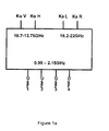
- the satellite Ka-band contains 3 sub-bands: the Extra Band (EB: 18.2 - 19.2 GHz), the Low Band (LB: 19.2-20.2 GHz) and the High Band (HB: 21.4 - 22 GHz). These three sub-bands are transmitted in two polarizations; left and right.
- EB Extra Band
- LB Low Band
- HB High Band
- the satellite Ku-band contains two sub-bands: the Low Band (LB: 10.7 - 11.7 GHz) and the High Band (HB: 11.7 - 12.75 GHz). These two sub-bands are transmitted in two polarizations; horizontal and vertical.
- LNB Quad Low-Noise-Block-down-converter
- Figure 1a A universal Quad Low-Noise-Block-down-converter (LNB) is shown in Figure 1a .
- This LNB down-converts the 3 frequency sub-bands in the Ka-band and the 2 sub-bands in the Ku-band towards a second intermediate frequency band, also known as the L-band (which has a bandwidth of 0.95-2.15 GHz) for each polarisation (horizontal and vertical for the Ku-band, and left and right for the Ka-band).
- the quad LNB shown in Figure 1a can handle up to 4 users, and can enable each user to independently and simultaneously select one subband out of all received sub-bands.
- Channel selection can take place using a television set top box (STB), for example.
- STB television set top box
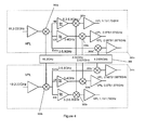
- FIG. 1b A block diagram of a state-of-the-art down-converter is shown in Figure 1b .
- This down-converter fulfils the functionality of the quad LNB shown in Figure 1a .
- noise levels in state-of-the-art solutions are in the sub-dB range. It is common for a first amplification to be performed by low noise amplifiers (I.NAs) realized in compound semiconductor technologies, i.e. pHEMT GaAs.
- I.NAs low noise amplifiers
- the traditional, as well as the state-of-the-art, architecture uses 5 local oscillators (LO) to perform direct down-conversion.
- LO local oscillators
- the LO generators operate at 9.75 GHz (LB) and 10.60 GHz (HB).
- LB 9.75 GHz
- HB 10.60 GHz
- these operating frequencies are 17.1 GHz (EB), 18.1 GHz (LB), and 20.35 GHz (HB).
- FIG. 1b The block diagram of Figure 1b illustrates the conversion of vertically (v) and horizontally (h) polarised Ku-band signals at frequencies between 10.70 and 12.75 GHz and right-hand (r) and left-hand (I) polarised Ka-band signals at frequencies between 19.20 and 22.00 GHz to four different output channels 171, 172, 173, 174.
- Each output channel 171, 172, 173, 174 has the same nominal output bandwidth (between 950 and 2150 MHz).
- the down-conversion process illustrated in Figure 1b is a multi-step process.
- First the v-Ku, h-Ku, r-Ka and I-Ka signals are separately fed into respective low noise amplifiers 101, 102, 103, 104 operating at radio frequencies.
- the output of each of the low noise amplifiers 101, 102, 103, 104 is fed to one of four signal splitters 111, 112, 113, 114.
- Each signal splitter 111, 112,113,114 has two output signals.
- Eight mixers 121-128 are required for the next stage in the process.
- Four mixers 121-124 are provided for the Ku-band, and four mixers 125-128 for the Ka-band.
- the mixers 121-128 are arranged in pairs. Each pair of mixers 121-128 receives a signal from one of four local oscillators 131-134.
- the local oscillators 131-134 shown in Figure 1b generate signals at 9.75 GHz 131 and 10.60 GHz 132 for the Ku-band mixers 121-124, and 18.1 GHz 133 and 20.35 GHz 134 for the Ka-band mixers 125-128.
- the two pairs of mixers 121-122, 123-124 in the Ku-band path each have a mixer 121, 123 receiving a signal from the v-Ku signal splitter 111 and a mixer 122, 124 receiving a signal from the h-Ku signal splitter 112.
- the two pairs of mixers 125-126. 127-128 in the Ka-band path each have a mixer 125, 127 receiving a signal from the r-Ka signal splitter 113 and a mixer 126, 128 receiving a signal from the I-Ka signal splitter 114.
- the eight mixers 121-128 provide their respective outputs to eight respective intermediate frequency (IF) amplifiers 141-148.
- the eight IF amplifiers 141-148 feed the amplified signals to a switching matrix (8 x 4) 150.
- the switching matrix 150 ensures that any of the four output channels 171-174 can receive any of the input RF signals (v-Ku, h-Ku, r-Ka or I-Ka) independently of the other output channels 171-174.
- Another IF amplifier stage 161-164 is provided between the switching matrix 150 and each of the output channels 171-174.
- a significant problem with the frequency plan used by the prior art solutions in Figure 1b is the generation of beat frequencies.
- the local oscillator signals of 9.75 GHz and 10.60 GHz result in a beat frequency of 850 MHz, for which the second harmonic is 1.7 GHz.
- This spurious tone falls directly in the IF band.
- the beat frequency of 1 GHz is close to the 20.35 GHz LO, which might result in pulling effects. Pulling effects occur when oscillators are located close to each other on the same die. In which case, one of the LO sources can disturb the other oscillator causing the resonant frequency of the other oscillator to shift.
- Embodiments of the present invention can provide a system and frequency plan where all of the LO frequencies required by the system can be derived from a single oscillator frequency.
- the use of a single phase-locked loop (PLL) is possible when an heterodyne down-conversion architecture is chosen.
- the local oscillator can be chosen to be 16.2 GHz for the Ka-band and 8-1 GHz (16.2 GHz divided by two) for the Ku-band.
- Figure 2a illustrates the Ka-band down-conversion spectrum according to an embodiment of the invention.
- Figures 3a, 3b and 4 illustrate an embodiment of the invention for implementing the down-conversion spectrum of Figure 2a .
- Figure 2a illustrates that a LO signal frequency 152a of 16.2 GHz (shown on the second line 152 of Figure 2a ) is used to down-convert the EB 151a, LB 151 b and HB 151c of the Ka-band at frequencies in the range of 18.2 - 22 GHz.
- This down-conversion generates an IF1 band 154a-154c of 2 - 5.8 GHz (shown on the bottom line 154). Consequently, the image frequencies 153a-153c are between 10.4 -14.2 GHz (shown on the third line 153).
- the second step in this down-conversion process is to convert the obtained IF band (IF1) to a second IF band (IF2).
- the second IF band (IF2) corresponds to the L-band as illustrated in Figure 2 .
- the frequencies related to this down-conversion are not shown in Figure 2a .
- the second step in this down-conversion process can be realized using local oscillator frequencies of 4.05 GHz (HB), 2.025 GHz (LB) and 1.0125 GHz (EB). These frequencies are integer related to 16.2 GHz which can be advantageous in terms of circuit implementation.
- integer division of the local oscillator frequency 152a with an even denominator is employed to obtain all of the required local oscillator frequencies for the Ka-band.
- the corresponding frequencies for this down-conversion scheme are provided in Table 1.
- Table 1 Frequency planning Ka-band.
- Careful filtering at IFs can be used to prevent problems with images and spurious tones. It should also be noted that a band used in the United States of America, 17.2 - 18.2 GHz, is directly converted to 1 - 2 GHz by the LO signal frequency 152a of 16.2 GHz by this conversion scheme. This is advantageous as it also falls within the L-band.
- Figure 2b illustrates Ku-band down-conversion according to an embodiment of the invention, which uses a similar technique to that of Figure 2a .
- the down-conversion of Figure 2b differs from Figure 2a as a first conversion with a LO frequency 8 1 GHz is used.
- Figures 3a, 3b and 4 illustrate an example circuit for implementing the down-conversion of Figure 2b .
- Figure 2b illustrates how a LO signal 156a with a frequency of 8.1 GHz (shown on the second line 156 of Figure 2a ) is used to down-convert the LB 155a and HB 155b of the Ku-band at frequencies of 10.7 - 12.85 GHz.
- This down-conversion generates an IF1 band 158a-158b of 2.6 - 4.65 GHz (shown on the bottom line 158). Consequently, the image frequencies 157a-157b are between 3.4 - 5.5 GHz (shown on the third line 157).
- the second step in down-conversion involves mixing local oscillator frequencies of 2.7 GHz (for the HB), and 1.62 GHz (for the LB) with IF1 to acquire IF2. All the corresponding frequencies are provided in Table 2. Note that 2.7 GHz is equal to 8-1 GHz / 3 and that 1.62 GHz is 8.1 GHz /5. That is, odd integer division of the local oscillator frequency 152a may be employed to obtain all of the required local oscillator frequencies for the Ku-band. Table 2: Frequency planning Ku-band.
- the PLLs can be based on VCOs running at 16.2 GHz and 9.1 GHz.
- the frequency spacing in this example is such that even the 2 nd harmonic of 9.1 GHz (18.2 GHz) will not pull the VCO running at 16.2 GHz because of the distance in frequency, and non-integer relationship, between 18.2 GHz and 16.2 GHz.
- FIGS 3a and 3b illustrate two embodiments according to the present invention.
- Tne embodiment of Figure 3a comprises a local oscillator 201a, three mixers 202a-204a and a frequency divider 205a.
- the arrangement of the mixers defines a 'heterodyne receive chain' 200a.
- the first stage mixer 202a mixes a received RF signal with a signal f 0a fed directly from the local oscillator 201a.
- f 0a is equal to a local oscillator frequency f LO .
- the first stage mixer 202a provides a first intermediate frequency signal IF 0 as an output
- the frequency divider 205a also receives the local oscillator signal f LO .
- the frequency divider 205a generates signals f 1a , f 2a which are derived from the signal f Lo from the local oscillator 201.
- the value 'n' may belong to the set of positive integers.
- the signals f 0a , f 1a ; f 2a are each of a different frequency.
- the first intermediate frequency signal IF 0 from the output of the first stage mixer 202a is provided as an input signal to two second stage mixers 203a, 204a.
- the second stage mixer 203a mixes the first intermediate frequency signal IF 0 with signal f 1a from the frequency divider 205 in order to generate an output intermediate frequency signal IF 1 .
- the second stage mixer 204a mixes the first intermediate frequency signal IF 0 with signal f 2a from the frequency divider 205 in order to generate an output intermediate frequency signal IF 2 .
- Figure 3b illustrates three mixers 202b - 204b within a heterodyne receive chain 200b that are arranged in the same way as the mixers 202a - 204c in Figure 3a .
- the arrangement of the local oscillator 201b and frequency divider 205b differs from the arrangement in Figure 3a .
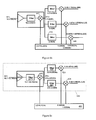
- FIG. 4 demonstrates how an embodiment of the present invention may be used to simultaneously down-convert multiple channels in the Ka-band.
- This example comprises two symmetrical heterodyne receive chains 300a, 300b.
- One of the heterodyne receive chains 300a may be used to down-convert a horizontally polarised Ka-band (h-Ka) signal
- the other receive chain 300b may be used to down-convert a vertically polarised Ka-band (v-Ka) signal.
- Each heterodyne receive chain 300a, 300b comprises a first stage mixer 302a, 302b and, in this example, three second stage mixers 303a, 304a, 306a, 303b, 344b, 306b.
- a local oscillator signal at 16.2 GHz is provided to the frequency divider 305.
- Figure 5a illustrates further details of the heterodyne receive chain 300a of Figure 4 that is used to down-convert the horizontal polarised Ka-band.
- the embodiment of Figure 5a uses the concept of heterodyne mixing to produce a first IF signal (IF1) between 2 GHz and 5.8 GHz using a LO signal frequency of 16.2 GHz.
- the first stage of the down-conversion process is achieved by a first stage mixer 402, which receives a Ka-band radio frequency (RF) signal (18.20 - 22.00 GHz) via an amplifier 407a and a band pass filter 4D7b.
- the amplifier 407a and filter 407b may provide selected frequency sensitivity in the Ka-band.
- the filter 407b may be necessary to select the desired RF band out of a broader range of frequencies in a received RF signal.
- the first stage mixer 402 mixes the RF signal, with a 16.2 GHz local oscillator signal provided by a frequency divider 405. It will be appreciated that in some examples the 16.2 GHz signal may be a local oscillator signal without frequency division.
- the output of the first stage mixer 402 contains a first intermediate frequency signal with a bandwidth of 2 - 5.8 GHz.
- the first intermediate frequency signal is fed to a number of second stage mixers 403, 404, 406, each second stage mixer belongs to a different branch for second stage down-conversion processing and provides a second intermediate frequency.
- the example shown in Figure 5a has three branches, one for each of the high (HB), low (LB) and extra (EB) bands.
- the HB second stage mixer 403 which is configured to output the high band (HB) signal, receives the first intermediate frequency signal from the first stage mixer 402 via a filter 408.
- the filter 408 is a band pass filter with a pass band of 5.2 - 5.8 GHz.
- the HB second stage mixer 403 mixes the filtered first intermediate frequency signal with a 4.05 GHz (LO/4) signal provided by the frequency divider 405.
- the output of the HB second stage mixer 403 is a second intermediate frequency signal, also referred to as an output intermediate frequency signal, with a bandwidth of 1.15 - 1.75 GHz.
- the output intermediate frequency signal is further filtered in this example by a band pass filter 410.
- the band pass filter 410 has the same nominal bandwidth as the output intermediate frequency signal and may provide further frequency selectivity, in some embodiments.
- the LB second stage mixer 404 which is configured to output the low band (LB) signal, receives the first intermediate frequency signal from the first stage mixer 402 via a filter 409.
- the filter 409 is a band pass filter with a pass band of 3 - 4 GHz.
- the LB second stage mixer 404 mixes the filtered first intermediate frequency signal with a 2.025 GHz (LO/B) signal provided by the frequency divider 405.
- the output of the LB second stage mixer 404 contains an output intermediate frequency signal with a bandwidth of 0.975 - 1.975 GHz.
- the output intermediate frequency signal is further filtered in this example by a band pass filter 411.
- the band pass filter 411 has the same nominal bandwidth as the output intermediate frequency signal and may provide further frequency selectivity, in some embodiments.
- the EB second stage mixer 406 which is configured to output the extra band (EB) signal, receives the first intermediate frequency signal directly from the output of the first stage mixer 402, in this example.
- a filter could be implemented between the output of the first stage mixer 402 and an input of the EB second stage mixer 406. The filter would, in this case, have a pass band of 2 - 3 GHz.
- the EB second stage mixer 406 mixes the filtered first intermediate frequency signal with a 1.0125 GHz (LO/16) signal provided by the frequency divider 405.
- the output of the EB second stage mixer 406 contains output intermediate frequency signals with a bandwidth of 0.9875 - 1.975 GHz.
- the output intermediate frequency signal is further filtered in this example by a band pass filter 412.
- the band pass filter 412 has a pass band of 0.9875 - 1.975 GHz.
- Figure 5b illustrates schematically a circuit that can perform a similar down-conversion process to that of the circuit of Figure 5a .
- a filter 453 is positioned between the output of the first stage mixer 442 and an input of the second stage mixer 446.
- Second stage mixer 446 relates to the EB second stage mixer 406 in Figure 5a .
- the filter 453 has a pass-band of 2 - 3 GHz.
- FIG. 5c shows an alternative embodiment of the invention, suitable for use as a Ku-band down-converter.
- a heterodyne receive chain 420 in this embodiment comprises a first stage mixer 422 and two second stage mixers 423, 424.
- the first stage mixer 422 receives an RF input at a frequency of 10.7 - 12.75 GHz via an amplifier 427a and a filter 427b.
- the amplifier 427a and filter 427b components have similar functions to their equivalents, amplifier 407a and filter 407b, described above with regard to Figure 5a .
- the filter 407b can be used to achieve low noise numbers (for example, single side-band can become double side-band) by filtering out images at 3 - 5.5GHz that occur when processing the 10.75GHz - 12.75Ghz RF band with a 8.1 GHz LO. These image frequencies are shown in Figure 2b
- the first stage mixer 422 also receives a local oscillator signal at 8.1 GHz from frequency divider 425.
- the first stage mixer 422 provides a first intermediate frequency signal within the band 2.6 - 4.65 GHz.
- a first branch of the heterodyne receive chain 420 comprises an HB second stage mixer 423 and a filter 428.
- the filter 428 is coupled between an output of the first stage mixer 422 and an input of the second stage mixer 423.
- the filter 428 is a band pass filter with a pass band of 3.6 - 4.65 GHz.
- the HB second stage mixer 423 also receives a 2.65 GHz (suitable for the high band Ku-band signal) local oscillator signal input from the frequency divider 425.
- the HB second stage mixer 423 produces an output intermediate frequency signal with a frequency of 0.95 - 2 GHz.
- a second branch of the heterodyne receive chain 420 comprises a LB second stage mixer 424 and a filter 429.
- the filter 429 is coupled between an output of the first stage mixer 422 and an input of the LB second stage mixer 424.
- the filter 429 is a band pass filter with a pass band of 2.6 - 3.6 GHz.
- the second stage mixer 424 also receives a 1.62 GHz (suitable for the low Ku-band signal) local oscillator signal input from the frequency divider 425.
- the second LB stage mixer 424 produces an output intermediate frequency signal with a frequency of 0.98 -1.98 GHz.
- an embodiment of the invention can be used to down-convert the Ka- and Ku-bands in a received RF signal to the intermediate frequencies within the L-band using local oscillator signals that are derived, by integer division, from a single local oscillator signal. This can be advantageous over the prior art as only a single oscillator is required and the interference between oscillating signals is reduced when compared with the prior art.
- Figure 6 shows an embodiment in which poly-phase filtering is utilised.
- the arrangement of various mixers and down-converters shown in this example is similar to that described previously with regard to Figure 5 , and will not be discussed further except where differences exist between the two examples.
- poly-phase filtering which is known in the art, can be used when it is possible to generate quadrature local oscillator signals at both the operating RF and IF.
- Poly-phase filtering allows more selective filtering (including discrimination between positive and negative frequencies).
- Embodiments employing poly-phase filtering allow the removal of the RF filter that is present before the first stage mixer in Figure 5a .
- a poly-phase filter (PPF) 501 is used after the first stage mixer 502.
- Providing a filter at IF, rather than at RF, can simplify the design requirements of the filter.
- the Q factor for the PPF 501 in figure 6 is 1, compared with a Q factor of 5.3 for the filter 407b operating on the RF signal in Figure 5a .
- PPF 501 operates on a first intermediate frequency signal.
- the PPF 501 can be used to overcome imperfections due to IQ imbalance at a frequency of a local oscillator (LO) and spurious responses around higher LO harmonics.
- the PPF 501 may be omitted in some embodiments.
- a combination of a single phase system and a poly-phase system is also possible in some embodiments.
- a single phase first stage mixer (such as that shown in Figure 4 ) can be used in combination with intermediate frequency poly-phase processing (such as that shown in Figure 6 ).
- the first stage mixer 501 of Figure 6 can be used with the second stage mixers 403, 404, 406 of Figure 5a . This allows the combination of poly-phase filtering at IF using IQ LO signals at IF with a single-phase LO signal at RF.
- FIG. 7 illustrates a circuit diagram demonstrating the arrangement of a frequency divider 600 suitable for use in the present invention.
- Frequency divider 600 comprises a phase-locked loop (PPL) architecture which maintains fixed output frequencies for supply to the first and second stage mixers of a down-converter.
- PPL phase-locked loop
- a voltage controlled oscillator (VCO) 601 can operate at a fixed frequency of 16.2 GHz. As discussed above, this output frequency is suitable for use by a first stage mixer for the Ka-band in one example.
- a first frequency divider block 602 receives the local oscillator signal frequency directly from VCO 601 and provides an 8.1 GHz frequency output signal suitable for a first stage mixer operating in the Ku-band.
- a second frequency divider block 603 receives the signal output by the first frequency divider block 602 and provides a 4.05 GHz output signal for a second stage mixer operating in the Ku-band (HB).
- a third frequency divider block 604 receives the signal output by the second frequency divider block 603 and provides a 2.025 GHz output signal for a second stage mixer operating in the Ka-band (LB).
- a fourth frequency divider block 605 receives the signal output by the third frequency divider bock 604 and provides a 1.0125 GHz signal for a second stage mixer operating in the Ka-band (EB).
- An additional frequency divider block 606 with a division ratio of 81 is provided in this example.
- the additional frequency divider block 606 receives the signal output by the second frequency divider block 603. and outputs a 50 MHz signal.
- the additional frequency divider 606 can be implemented with 6 cascaded 2/3-divider cells with a fixed division-by-2 or division-by-3 operation.
- An output of the additional frequency divider block 606 may be provided to a phase frequency detector (PFD) 607.
- the PFD 607 also receives a fixed frequency input signal of 50 MHz from a frequency doubler 608 which receives a reference frequency of 25 MHz from a crystal oscillator (not shown).
- the output of the PFD 607 is provided to a charge pump and discrete components 609, which behave in their conventional manner within a phase locked loop (PPL) arrangement
- PPL phase locked loop
- An advantage of embodiments of the present invention is that a requirement for multiple local oscillators within a multi-band down-converter can be removes.
- a further advantage is that intra-mixer interference caused by the presence of multiple local oscillator signals may be reduced.
- Another advantage of embodiments of the present invention is that a multi-band down-converter may be implemented on a single integrated circuit, rather than as a plurality of discrete components.
- any components that are described herein as being coupled or connected could be directly or indirectly coupled or connected. That is, one or more components could be located between two components that are said to be coupled or connected whilst still enabling the required functional to be achieved.
Landscapes
- Engineering & Computer Science (AREA)
- Power Engineering (AREA)
- Superheterodyne Receivers (AREA)
Priority Applications (3)
| Application Number | Priority Date | Filing Date | Title |
|---|---|---|---|
| EP11250679.5A EP2552016B1 (fr) | 2011-07-28 | 2011-07-28 | Convertisseur abaisseur de fréquence |
| US13/558,131 US8805309B2 (en) | 2011-07-28 | 2012-07-25 | Down-converter |
| CN201210262498.XA CN102904529B (zh) | 2011-07-28 | 2012-07-26 | 下变频器 |
Applications Claiming Priority (1)
| Application Number | Priority Date | Filing Date | Title |
|---|---|---|---|
| EP11250679.5A EP2552016B1 (fr) | 2011-07-28 | 2011-07-28 | Convertisseur abaisseur de fréquence |
Publications (2)
| Publication Number | Publication Date |
|---|---|
| EP2552016A1 true EP2552016A1 (fr) | 2013-01-30 |
| EP2552016B1 EP2552016B1 (fr) | 2014-06-25 |
Family
ID=44651519
Family Applications (1)
| Application Number | Title | Priority Date | Filing Date |
|---|---|---|---|
| EP11250679.5A Not-in-force EP2552016B1 (fr) | 2011-07-28 | 2011-07-28 | Convertisseur abaisseur de fréquence |
Country Status (3)
| Country | Link |
|---|---|
| US (1) | US8805309B2 (fr) |
| EP (1) | EP2552016B1 (fr) |
| CN (1) | CN102904529B (fr) |
Families Citing this family (13)
| Publication number | Priority date | Publication date | Assignee | Title |
|---|---|---|---|---|
| US8948716B2 (en) * | 2012-04-23 | 2015-02-03 | Entropic Communications, Inc. | Apparatuses and methods for conversion of radio frequency (RF) signals to intermediate frequency (IF) signals |
| FR3002345A1 (fr) * | 2013-02-15 | 2014-08-22 | St Microelectronics Sa | Procede et dispositif d'emission d'un signal radiofrequence |
| US9635310B2 (en) * | 2013-05-05 | 2017-04-25 | Maxlinear, Inc. | Band translation with protection of in-home networks |
| TWI560997B (en) * | 2013-09-23 | 2016-12-01 | Wistron Neweb Corp | Signal converter |
| CN103702165A (zh) * | 2014-01-09 | 2014-04-02 | 珠海迈科电子科技有限公司 | 一种具有对ka波段卫星信号接收处理功能的机顶盒 |
| US9548779B2 (en) * | 2014-04-03 | 2017-01-17 | Rafael Microelectronics, Inc. | Multi-user satellite receiving system and method thereof |
| US9379749B2 (en) * | 2014-05-15 | 2016-06-28 | Qualcomm Incorporated | VCO-coupling mitigation in a multiple-carrier, carrier aggregation receiver |
| US9548774B2 (en) | 2015-02-19 | 2017-01-17 | Qualcomm Incorporated | Signal generator with image rejection |
| US9793935B2 (en) * | 2015-07-02 | 2017-10-17 | Mediatek Inc. | Multi-mixer system and method for reducing interference within multi-mixer system |
| US9496908B1 (en) * | 2016-04-12 | 2016-11-15 | General Dynamics Mission Systems, Inc. | Superheterodyne receiver with improved immunity to spurious noise interference |
| CN106027075B (zh) * | 2016-04-29 | 2018-06-19 | 北京邮电大学 | 一种共时双频接收系统 |
| US10177873B1 (en) * | 2018-05-04 | 2019-01-08 | Qualcomm Incorporated | Concurrent support for multiple frequency bands for satellite navigation signals |
| GB202101010D0 (en) * | 2021-01-26 | 2021-03-10 | Nordic Semiconductor Asa | Multiband radio receivers |
Citations (3)
| Publication number | Priority date | Publication date | Assignee | Title |
|---|---|---|---|---|
| US4580289A (en) * | 1981-12-30 | 1986-04-01 | Motorola, Inc. | Fully integratable superheterodyne radio receiver utilizing tunable filters |
| EP1096667A1 (fr) * | 1999-10-29 | 2001-05-02 | Sharp Kabushiki Kaisha | Dispositif de réception partagé par plusieurs dispositifs d'accord |
| EP1696581A1 (fr) * | 2004-03-04 | 2006-08-30 | Matsushita Electric Industrial Co., Ltd. | Circuit de division de frequence et dispositif radio multimode utilisant |
Family Cites Families (22)
| Publication number | Priority date | Publication date | Assignee | Title |
|---|---|---|---|---|
| CN1056255C (zh) * | 1993-01-30 | 2000-09-06 | 汤姆森电子消费品公司 | 变频器 |
| US6088348A (en) * | 1998-07-13 | 2000-07-11 | Qualcom Incorporated | Configurable single and dual VCOs for dual- and tri-band wireless communication systems |
| US6584090B1 (en) * | 1999-04-23 | 2003-06-24 | Skyworks Solutions, Inc. | System and process for shared functional block CDMA and GSM communication transceivers |
| US7277727B1 (en) * | 2000-11-22 | 2007-10-02 | Sprint Communications Company L.P. | System and method for processing a signal |
| US6675003B1 (en) * | 2000-12-07 | 2004-01-06 | Sirf Technology, Inc. | L1/L2 GPS receiver |
| SE519614C2 (sv) * | 2001-07-18 | 2003-03-18 | Spirea Ab | Flerstandardssändtagare med trebandsarkitektur för WLAN |
| US7277679B1 (en) * | 2001-09-28 | 2007-10-02 | Arraycomm, Llc | Method and apparatus to provide multiple-mode spatial processing to a terminal unit |
| US7260416B2 (en) * | 2003-01-21 | 2007-08-21 | Qualcomm Incorporated | Shared receive path for simultaneous received signals |
| US7003274B1 (en) * | 2003-03-05 | 2006-02-21 | Cisco Systems Wireless Networking (Australia) Pty Limited | Frequency synthesizer and synthesis method for generating a multiband local oscillator signal |
| JP4298468B2 (ja) * | 2003-10-31 | 2009-07-22 | シャープ株式会社 | 周波数変換回路、無線周波受信機、および無線周波トランシーバ |
| EP1735905B1 (fr) * | 2004-03-12 | 2009-08-12 | R.F. Magic Inc. | Melangeur et syntoniseur a suppression d'harmoniques |
| US7272375B2 (en) * | 2004-06-30 | 2007-09-18 | Silicon Laboratories Inc. | Integrated low-IF terrestrial audio broadcast receiver and associated method |
| US7551127B2 (en) * | 2005-02-10 | 2009-06-23 | Motorola, Inc. | Reconfigurable downconverter for a multi-band positioning receiver |
| US7937052B2 (en) * | 2006-06-27 | 2011-05-03 | Cisco Technology, Inc. | Multiple input multiple output signal receiving apparatus with optimized performance |
| US8081699B2 (en) * | 2006-07-15 | 2011-12-20 | Kazimierz Siwiak | Wireless communication system and method with elliptically polarized radio frequency signals |
| US7598815B2 (en) * | 2006-10-25 | 2009-10-06 | Agere Systems Inc. | Multiple frequency generator for quadrature amplitude modulated communications |
| PT2087623E (pt) * | 2006-11-03 | 2010-10-21 | Rf Magic Inc | Transposição e sobreposição de frequência do sinal de satélite |
| JP4775234B2 (ja) * | 2006-11-20 | 2011-09-21 | 株式会社デンソー | 周波数変換回路及び衛星測位信号受信装置 |
| EP2141819A1 (fr) * | 2008-07-04 | 2010-01-06 | Telefonaktiebolaget LM Ericsson (publ) | Dispositif et procédé de traitement de signal |
| US8583170B2 (en) * | 2009-02-16 | 2013-11-12 | Telefonaktiebolaget Lm Ericsson (Publ) | Multi-band aggregated spectrum receiver employing frequency source reuse |
| US20100261500A1 (en) * | 2009-04-09 | 2010-10-14 | Broadcom Corporation | Multiple frequency band multiple standard information signal modular baseband processing module |
| EP2383914B1 (fr) * | 2010-04-30 | 2015-01-28 | Nxp B.V. | Réduction de l'éperon numérique RF |
-
2011
- 2011-07-28 EP EP11250679.5A patent/EP2552016B1/fr not_active Not-in-force
-
2012
- 2012-07-25 US US13/558,131 patent/US8805309B2/en active Active
- 2012-07-26 CN CN201210262498.XA patent/CN102904529B/zh not_active Expired - Fee Related
Patent Citations (3)
| Publication number | Priority date | Publication date | Assignee | Title |
|---|---|---|---|---|
| US4580289A (en) * | 1981-12-30 | 1986-04-01 | Motorola, Inc. | Fully integratable superheterodyne radio receiver utilizing tunable filters |
| EP1096667A1 (fr) * | 1999-10-29 | 2001-05-02 | Sharp Kabushiki Kaisha | Dispositif de réception partagé par plusieurs dispositifs d'accord |
| EP1696581A1 (fr) * | 2004-03-04 | 2006-08-30 | Matsushita Electric Industrial Co., Ltd. | Circuit de division de frequence et dispositif radio multimode utilisant |
Also Published As
| Publication number | Publication date |
|---|---|
| US20130028352A1 (en) | 2013-01-31 |
| CN102904529A (zh) | 2013-01-30 |
| US8805309B2 (en) | 2014-08-12 |
| EP2552016B1 (fr) | 2014-06-25 |
| CN102904529B (zh) | 2015-06-10 |
Similar Documents
| Publication | Publication Date | Title |
|---|---|---|
| EP2552016B1 (fr) | Convertisseur abaisseur de fréquence | |
| US6766178B1 (en) | RF architecture for cellular multi-band telephones | |
| KR101913238B1 (ko) | 무선 주파수 수신기 및 수신 방법 | |
| KR100540409B1 (ko) | 다중 모드 직접 변환 수신기 | |
| US7003274B1 (en) | Frequency synthesizer and synthesis method for generating a multiband local oscillator signal | |
| EP2136468B1 (fr) | Mélangeur de suppression d'harmoniques et syntoniseur | |
| CN100438347C (zh) | 频率转换器及其方法、用于解调信号的方法 | |
| US7327993B2 (en) | Low leakage local oscillator system | |
| US20160294591A1 (en) | Multichannel receiver | |
| US20120139586A1 (en) | Frequency synthesizer and frequency synthesizing method | |
| WO1998052292A1 (fr) | Recepteur radio a deux bandes | |
| JP2003198401A (ja) | チューナ装置とその据付けボックス | |
| US9735785B2 (en) | Apparatuses and methods for conversion of radio frequency (RF) signals to intermediate frequency (IF) signals | |
| US11064446B2 (en) | Apparatus and methods for wideband receivers | |
| CN111886889B (zh) | 多频带聚合接收器架构 | |
| US7324797B2 (en) | Bragg-cell application to high probability of intercept receiver | |
| US8744380B2 (en) | Unified frequency synthesizer for direct conversion receiver or transmitter | |
| US20080113641A1 (en) | Radio communication apparatus and frequency generating method thereof | |
| US7376396B2 (en) | Ratiometric transmit path architecture for communication systems | |
| KR100837115B1 (ko) | 이중 무선 주파수 수신 회로 및 그 제어 방법 | |
| US20060003707A1 (en) | Weighted mixing circuitry for quadrature processing in communication systems | |
| HK1081744B (en) | A frequency converter and the method thereof, and a method for demodualting signals |
Legal Events
| Date | Code | Title | Description |
|---|---|---|---|
| PUAI | Public reference made under article 153(3) epc to a published international application that has entered the european phase |
Free format text: ORIGINAL CODE: 0009012 |
|
| AK | Designated contracting states |
Kind code of ref document: A1 Designated state(s): AL AT BE BG CH CY CZ DE DK EE ES FI FR GB GR HR HU IE IS IT LI LT LU LV MC MK MT NL NO PL PT RO RS SE SI SK SM TR |
|
| AX | Request for extension of the european patent |
Extension state: BA ME |
|
| 17P | Request for examination filed |
Effective date: 20130730 |
|
| RBV | Designated contracting states (corrected) |
Designated state(s): AL AT BE BG CH CY CZ DE DK EE ES FI FR GB GR HR HU IE IS IT LI LT LU LV MC MK MT NL NO PL PT RO RS SE SI SK SM TR |
|
| GRAP | Despatch of communication of intention to grant a patent |
Free format text: ORIGINAL CODE: EPIDOSNIGR1 |
|
| INTG | Intention to grant announced |
Effective date: 20130920 |
|
| RIC1 | Information provided on ipc code assigned before grant |
Ipc: H03D 7/16 20060101AFI20130906BHEP |
|
| GRAP | Despatch of communication of intention to grant a patent |
Free format text: ORIGINAL CODE: EPIDOSNIGR1 |
|
| INTG | Intention to grant announced |
Effective date: 20140129 |
|
| GRAS | Grant fee paid |
Free format text: ORIGINAL CODE: EPIDOSNIGR3 |
|
| GRAA | (expected) grant |
Free format text: ORIGINAL CODE: 0009210 |
|
| AK | Designated contracting states |
Kind code of ref document: B1 Designated state(s): AL AT BE BG CH CY CZ DE DK EE ES FI FR GB GR HR HU IE IS IT LI LT LU LV MC MK MT NL NO PL PT RO RS SE SI SK SM TR |
|
| REG | Reference to a national code |
Ref country code: GB Ref legal event code: FG4D |
|
| REG | Reference to a national code |
Ref country code: CH Ref legal event code: EP |
|
| REG | Reference to a national code |
Ref country code: AT Ref legal event code: REF Ref document number: 675215 Country of ref document: AT Kind code of ref document: T Effective date: 20140715 |
|
| REG | Reference to a national code |
Ref country code: IE Ref legal event code: FG4D |
|
| REG | Reference to a national code |
Ref country code: DE Ref legal event code: R096 Ref document number: 602011007915 Country of ref document: DE Effective date: 20140807 |
|
| PG25 | Lapsed in a contracting state [announced via postgrant information from national office to epo] |
Ref country code: CY Free format text: LAPSE BECAUSE OF FAILURE TO SUBMIT A TRANSLATION OF THE DESCRIPTION OR TO PAY THE FEE WITHIN THE PRESCRIBED TIME-LIMIT Effective date: 20140625 Ref country code: LT Free format text: LAPSE BECAUSE OF FAILURE TO SUBMIT A TRANSLATION OF THE DESCRIPTION OR TO PAY THE FEE WITHIN THE PRESCRIBED TIME-LIMIT Effective date: 20140625 Ref country code: NO Free format text: LAPSE BECAUSE OF FAILURE TO SUBMIT A TRANSLATION OF THE DESCRIPTION OR TO PAY THE FEE WITHIN THE PRESCRIBED TIME-LIMIT Effective date: 20140925 Ref country code: GR Free format text: LAPSE BECAUSE OF FAILURE TO SUBMIT A TRANSLATION OF THE DESCRIPTION OR TO PAY THE FEE WITHIN THE PRESCRIBED TIME-LIMIT Effective date: 20140926 Ref country code: FI Free format text: LAPSE BECAUSE OF FAILURE TO SUBMIT A TRANSLATION OF THE DESCRIPTION OR TO PAY THE FEE WITHIN THE PRESCRIBED TIME-LIMIT Effective date: 20140625 |
|
| REG | Reference to a national code |
Ref country code: AT Ref legal event code: MK05 Ref document number: 675215 Country of ref document: AT Kind code of ref document: T Effective date: 20140625 |
|
| REG | Reference to a national code |
Ref country code: NL Ref legal event code: VDEP Effective date: 20140625 |
|
| REG | Reference to a national code |
Ref country code: LT Ref legal event code: MG4D |
|
| PG25 | Lapsed in a contracting state [announced via postgrant information from national office to epo] |
Ref country code: LV Free format text: LAPSE BECAUSE OF FAILURE TO SUBMIT A TRANSLATION OF THE DESCRIPTION OR TO PAY THE FEE WITHIN THE PRESCRIBED TIME-LIMIT Effective date: 20140625 Ref country code: SE Free format text: LAPSE BECAUSE OF FAILURE TO SUBMIT A TRANSLATION OF THE DESCRIPTION OR TO PAY THE FEE WITHIN THE PRESCRIBED TIME-LIMIT Effective date: 20140625 Ref country code: RS Free format text: LAPSE BECAUSE OF FAILURE TO SUBMIT A TRANSLATION OF THE DESCRIPTION OR TO PAY THE FEE WITHIN THE PRESCRIBED TIME-LIMIT Effective date: 20140625 Ref country code: HR Free format text: LAPSE BECAUSE OF FAILURE TO SUBMIT A TRANSLATION OF THE DESCRIPTION OR TO PAY THE FEE WITHIN THE PRESCRIBED TIME-LIMIT Effective date: 20140625 |
|
| PG25 | Lapsed in a contracting state [announced via postgrant information from national office to epo] |
Ref country code: ES Free format text: LAPSE BECAUSE OF FAILURE TO SUBMIT A TRANSLATION OF THE DESCRIPTION OR TO PAY THE FEE WITHIN THE PRESCRIBED TIME-LIMIT Effective date: 20140625 Ref country code: CZ Free format text: LAPSE BECAUSE OF FAILURE TO SUBMIT A TRANSLATION OF THE DESCRIPTION OR TO PAY THE FEE WITHIN THE PRESCRIBED TIME-LIMIT Effective date: 20140625 Ref country code: EE Free format text: LAPSE BECAUSE OF FAILURE TO SUBMIT A TRANSLATION OF THE DESCRIPTION OR TO PAY THE FEE WITHIN THE PRESCRIBED TIME-LIMIT Effective date: 20140625 Ref country code: PT Free format text: LAPSE BECAUSE OF FAILURE TO SUBMIT A TRANSLATION OF THE DESCRIPTION OR TO PAY THE FEE WITHIN THE PRESCRIBED TIME-LIMIT Effective date: 20141027 Ref country code: SK Free format text: LAPSE BECAUSE OF FAILURE TO SUBMIT A TRANSLATION OF THE DESCRIPTION OR TO PAY THE FEE WITHIN THE PRESCRIBED TIME-LIMIT Effective date: 20140625 Ref country code: RO Free format text: LAPSE BECAUSE OF FAILURE TO SUBMIT A TRANSLATION OF THE DESCRIPTION OR TO PAY THE FEE WITHIN THE PRESCRIBED TIME-LIMIT Effective date: 20140625 |
|
| PG25 | Lapsed in a contracting state [announced via postgrant information from national office to epo] |
Ref country code: NL Free format text: LAPSE BECAUSE OF FAILURE TO SUBMIT A TRANSLATION OF THE DESCRIPTION OR TO PAY THE FEE WITHIN THE PRESCRIBED TIME-LIMIT Effective date: 20140625 Ref country code: AT Free format text: LAPSE BECAUSE OF FAILURE TO SUBMIT A TRANSLATION OF THE DESCRIPTION OR TO PAY THE FEE WITHIN THE PRESCRIBED TIME-LIMIT Effective date: 20140625 Ref country code: IS Free format text: LAPSE BECAUSE OF FAILURE TO SUBMIT A TRANSLATION OF THE DESCRIPTION OR TO PAY THE FEE WITHIN THE PRESCRIBED TIME-LIMIT Effective date: 20141025 Ref country code: PL Free format text: LAPSE BECAUSE OF FAILURE TO SUBMIT A TRANSLATION OF THE DESCRIPTION OR TO PAY THE FEE WITHIN THE PRESCRIBED TIME-LIMIT Effective date: 20140625 |
|
| REG | Reference to a national code |
Ref country code: CH Ref legal event code: PL |
|
| REG | Reference to a national code |
Ref country code: DE Ref legal event code: R097 Ref document number: 602011007915 Country of ref document: DE |
|
| PG25 | Lapsed in a contracting state [announced via postgrant information from national office to epo] |
Ref country code: MC Free format text: LAPSE BECAUSE OF FAILURE TO SUBMIT A TRANSLATION OF THE DESCRIPTION OR TO PAY THE FEE WITHIN THE PRESCRIBED TIME-LIMIT Effective date: 20140625 |
|
| REG | Reference to a national code |
Ref country code: IE Ref legal event code: MM4A |
|
| PG25 | Lapsed in a contracting state [announced via postgrant information from national office to epo] |
Ref country code: LI Free format text: LAPSE BECAUSE OF NON-PAYMENT OF DUE FEES Effective date: 20140731 Ref country code: CH Free format text: LAPSE BECAUSE OF NON-PAYMENT OF DUE FEES Effective date: 20140731 Ref country code: IT Free format text: LAPSE BECAUSE OF FAILURE TO SUBMIT A TRANSLATION OF THE DESCRIPTION OR TO PAY THE FEE WITHIN THE PRESCRIBED TIME-LIMIT Effective date: 20140625 Ref country code: DK Free format text: LAPSE BECAUSE OF FAILURE TO SUBMIT A TRANSLATION OF THE DESCRIPTION OR TO PAY THE FEE WITHIN THE PRESCRIBED TIME-LIMIT Effective date: 20140625 |
|
| PLBE | No opposition filed within time limit |
Free format text: ORIGINAL CODE: 0009261 |
|
| STAA | Information on the status of an ep patent application or granted ep patent |
Free format text: STATUS: NO OPPOSITION FILED WITHIN TIME LIMIT |
|
| 26N | No opposition filed |
Effective date: 20150326 |
|
| PG25 | Lapsed in a contracting state [announced via postgrant information from national office to epo] |
Ref country code: BE Free format text: LAPSE BECAUSE OF FAILURE TO SUBMIT A TRANSLATION OF THE DESCRIPTION OR TO PAY THE FEE WITHIN THE PRESCRIBED TIME-LIMIT Effective date: 20140625 |
|
| PG25 | Lapsed in a contracting state [announced via postgrant information from national office to epo] |
Ref country code: IE Free format text: LAPSE BECAUSE OF NON-PAYMENT OF DUE FEES Effective date: 20140728 |
|
| PG25 | Lapsed in a contracting state [announced via postgrant information from national office to epo] |
Ref country code: SI Free format text: LAPSE BECAUSE OF FAILURE TO SUBMIT A TRANSLATION OF THE DESCRIPTION OR TO PAY THE FEE WITHIN THE PRESCRIBED TIME-LIMIT Effective date: 20140625 |
|
| GBPC | Gb: european patent ceased through non-payment of renewal fee |
Effective date: 20150728 |
|
| PG25 | Lapsed in a contracting state [announced via postgrant information from national office to epo] |
Ref country code: SM Free format text: LAPSE BECAUSE OF FAILURE TO SUBMIT A TRANSLATION OF THE DESCRIPTION OR TO PAY THE FEE WITHIN THE PRESCRIBED TIME-LIMIT Effective date: 20140625 Ref country code: GB Free format text: LAPSE BECAUSE OF NON-PAYMENT OF DUE FEES Effective date: 20150728 |
|
| REG | Reference to a national code |
Ref country code: FR Ref legal event code: PLFP Year of fee payment: 6 |
|
| PG25 | Lapsed in a contracting state [announced via postgrant information from national office to epo] |
Ref country code: MT Free format text: LAPSE BECAUSE OF FAILURE TO SUBMIT A TRANSLATION OF THE DESCRIPTION OR TO PAY THE FEE WITHIN THE PRESCRIBED TIME-LIMIT Effective date: 20140625 Ref country code: BG Free format text: LAPSE BECAUSE OF FAILURE TO SUBMIT A TRANSLATION OF THE DESCRIPTION OR TO PAY THE FEE WITHIN THE PRESCRIBED TIME-LIMIT Effective date: 20140625 |
|
| PG25 | Lapsed in a contracting state [announced via postgrant information from national office to epo] |
Ref country code: LU Free format text: LAPSE BECAUSE OF NON-PAYMENT OF DUE FEES Effective date: 20140728 Ref country code: HU Free format text: LAPSE BECAUSE OF FAILURE TO SUBMIT A TRANSLATION OF THE DESCRIPTION OR TO PAY THE FEE WITHIN THE PRESCRIBED TIME-LIMIT; INVALID AB INITIO Effective date: 20110728 Ref country code: TR Free format text: LAPSE BECAUSE OF FAILURE TO SUBMIT A TRANSLATION OF THE DESCRIPTION OR TO PAY THE FEE WITHIN THE PRESCRIBED TIME-LIMIT Effective date: 20140625 |
|
| REG | Reference to a national code |
Ref country code: FR Ref legal event code: PLFP Year of fee payment: 7 |
|
| REG | Reference to a national code |
Ref country code: FR Ref legal event code: PLFP Year of fee payment: 8 |
|
| PG25 | Lapsed in a contracting state [announced via postgrant information from national office to epo] |
Ref country code: MK Free format text: LAPSE BECAUSE OF FAILURE TO SUBMIT A TRANSLATION OF THE DESCRIPTION OR TO PAY THE FEE WITHIN THE PRESCRIBED TIME-LIMIT Effective date: 20140625 |
|
| PG25 | Lapsed in a contracting state [announced via postgrant information from national office to epo] |
Ref country code: AL Free format text: LAPSE BECAUSE OF FAILURE TO SUBMIT A TRANSLATION OF THE DESCRIPTION OR TO PAY THE FEE WITHIN THE PRESCRIBED TIME-LIMIT Effective date: 20140625 |
|
| PGFP | Annual fee paid to national office [announced via postgrant information from national office to epo] |
Ref country code: FR Payment date: 20190621 Year of fee payment: 9 |
|
| PGFP | Annual fee paid to national office [announced via postgrant information from national office to epo] |
Ref country code: DE Payment date: 20190620 Year of fee payment: 9 |
|
| REG | Reference to a national code |
Ref country code: DE Ref legal event code: R119 Ref document number: 602011007915 Country of ref document: DE |
|
| PG25 | Lapsed in a contracting state [announced via postgrant information from national office to epo] |
Ref country code: FR Free format text: LAPSE BECAUSE OF NON-PAYMENT OF DUE FEES Effective date: 20200731 |
|
| PG25 | Lapsed in a contracting state [announced via postgrant information from national office to epo] |
Ref country code: DE Free format text: LAPSE BECAUSE OF NON-PAYMENT OF DUE FEES Effective date: 20210202 |