EP2551662A1 - Optische Gasanalysatoreinrichtung mit Mitteln zum Verbessern der Selektivität bei Gasgemischanalysen - Google Patents
Optische Gasanalysatoreinrichtung mit Mitteln zum Verbessern der Selektivität bei Gasgemischanalysen Download PDFInfo
- Publication number
- EP2551662A1 EP2551662A1 EP12005326A EP12005326A EP2551662A1 EP 2551662 A1 EP2551662 A1 EP 2551662A1 EP 12005326 A EP12005326 A EP 12005326A EP 12005326 A EP12005326 A EP 12005326A EP 2551662 A1 EP2551662 A1 EP 2551662A1
- Authority
- EP
- European Patent Office
- Prior art keywords
- gas
- optical
- opto
- measuring
- analyzer device
- Prior art date
- Legal status (The legal status is an assumption and is not a legal conclusion. Google has not performed a legal analysis and makes no representation as to the accuracy of the status listed.)
- Granted
Links
- 230000003287 optical effect Effects 0.000 title claims abstract description 53
- 238000004458 analytical method Methods 0.000 title claims abstract description 9
- 239000000203 mixture Substances 0.000 title claims description 13
- 238000004868 gas analysis Methods 0.000 title description 2
- 238000005259 measurement Methods 0.000 claims abstract description 21
- 230000005855 radiation Effects 0.000 claims abstract description 20
- 238000010521 absorption reaction Methods 0.000 claims abstract description 14
- 238000011144 upstream manufacturing Methods 0.000 claims abstract description 10
- 238000004590 computer program Methods 0.000 claims abstract 3
- 238000001745 non-dispersive infrared spectroscopy Methods 0.000 claims description 13
- 238000012545 processing Methods 0.000 claims description 10
- 238000011156 evaluation Methods 0.000 claims description 8
- 230000035945 sensitivity Effects 0.000 claims description 6
- 230000002238 attenuated effect Effects 0.000 claims description 4
- 230000003071 parasitic effect Effects 0.000 claims 1
- 238000004611 spectroscopical analysis Methods 0.000 abstract description 2
- 239000007789 gas Substances 0.000 description 78
- 230000009102 absorption Effects 0.000 description 12
- 230000002452 interceptive effect Effects 0.000 description 7
- 230000003595 spectral effect Effects 0.000 description 6
- 230000005540 biological transmission Effects 0.000 description 5
- 238000001514 detection method Methods 0.000 description 4
- 239000011159 matrix material Substances 0.000 description 4
- 238000012937 correction Methods 0.000 description 3
- 239000013078 crystal Substances 0.000 description 3
- 230000000694 effects Effects 0.000 description 3
- 239000000463 material Substances 0.000 description 3
- CURLTUGMZLYLDI-UHFFFAOYSA-N Carbon dioxide Chemical compound O=C=O CURLTUGMZLYLDI-UHFFFAOYSA-N 0.000 description 2
- UGFAIRIUMAVXCW-UHFFFAOYSA-N Carbon monoxide Chemical compound [O+]#[C-] UGFAIRIUMAVXCW-UHFFFAOYSA-N 0.000 description 2
- 229910002091 carbon monoxide Inorganic materials 0.000 description 2
- 230000008859 change Effects 0.000 description 2
- 238000013461 design Methods 0.000 description 2
- 230000008030 elimination Effects 0.000 description 2
- 238000003379 elimination reaction Methods 0.000 description 2
- 238000004519 manufacturing process Methods 0.000 description 2
- 230000010287 polarization Effects 0.000 description 2
- 238000012628 principal component regression Methods 0.000 description 2
- 230000001629 suppression Effects 0.000 description 2
- 238000005033 Fourier transform infrared spectroscopy Methods 0.000 description 1
- 239000003990 capacitor Substances 0.000 description 1
- 229910002092 carbon dioxide Inorganic materials 0.000 description 1
- 239000001569 carbon dioxide Substances 0.000 description 1
- 239000000919 ceramic Substances 0.000 description 1
- 230000001419 dependent effect Effects 0.000 description 1
- 238000011161 development Methods 0.000 description 1
- 230000018109 developmental process Effects 0.000 description 1
- 238000010586 diagram Methods 0.000 description 1
- 230000002349 favourable effect Effects 0.000 description 1
- 238000004817 gas chromatography Methods 0.000 description 1
- 108010067216 glycyl-glycyl-glycine Proteins 0.000 description 1
- 238000010348 incorporation Methods 0.000 description 1
- 238000012423 maintenance Methods 0.000 description 1
- 239000012528 membrane Substances 0.000 description 1
- 238000000034 method Methods 0.000 description 1
- 238000012986 modification Methods 0.000 description 1
- 230000004048 modification Effects 0.000 description 1
- 238000012544 monitoring process Methods 0.000 description 1
- 238000000491 multivariate analysis Methods 0.000 description 1
- 230000000737 periodic effect Effects 0.000 description 1
- 230000010363 phase shift Effects 0.000 description 1
- 238000000513 principal component analysis Methods 0.000 description 1
- 230000008569 process Effects 0.000 description 1
- 230000004044 response Effects 0.000 description 1
- 238000001228 spectrum Methods 0.000 description 1
- 238000012360 testing method Methods 0.000 description 1
- 238000000411 transmission spectrum Methods 0.000 description 1
- GZXOHHPYODFEGO-UHFFFAOYSA-N triglycine sulfate Chemical compound NCC(O)=O.NCC(O)=O.NCC(O)=O.OS(O)(=O)=O GZXOHHPYODFEGO-UHFFFAOYSA-N 0.000 description 1
Images
Classifications
-
- G—PHYSICS
- G01—MEASURING; TESTING
- G01N—INVESTIGATING OR ANALYSING MATERIALS BY DETERMINING THEIR CHEMICAL OR PHYSICAL PROPERTIES
- G01N21/00—Investigating or analysing materials by the use of optical means, i.e. using sub-millimetre waves, infrared, visible or ultraviolet light
- G01N21/17—Systems in which incident light is modified in accordance with the properties of the material investigated
- G01N21/25—Colour; Spectral properties, i.e. comparison of effect of material on the light at two or more different wavelengths or wavelength bands
- G01N21/31—Investigating relative effect of material at wavelengths characteristic of specific elements or molecules, e.g. atomic absorption spectrometry
- G01N21/35—Investigating relative effect of material at wavelengths characteristic of specific elements or molecules, e.g. atomic absorption spectrometry using infrared light
- G01N21/37—Investigating relative effect of material at wavelengths characteristic of specific elements or molecules, e.g. atomic absorption spectrometry using infrared light using pneumatic detection
-
- G—PHYSICS
- G01—MEASURING; TESTING
- G01N—INVESTIGATING OR ANALYSING MATERIALS BY DETERMINING THEIR CHEMICAL OR PHYSICAL PROPERTIES
- G01N21/00—Investigating or analysing materials by the use of optical means, i.e. using sub-millimetre waves, infrared, visible or ultraviolet light
- G01N21/17—Systems in which incident light is modified in accordance with the properties of the material investigated
- G01N21/25—Colour; Spectral properties, i.e. comparison of effect of material on the light at two or more different wavelengths or wavelength bands
- G01N21/31—Investigating relative effect of material at wavelengths characteristic of specific elements or molecules, e.g. atomic absorption spectrometry
- G01N21/35—Investigating relative effect of material at wavelengths characteristic of specific elements or molecules, e.g. atomic absorption spectrometry using infrared light
- G01N21/3504—Investigating relative effect of material at wavelengths characteristic of specific elements or molecules, e.g. atomic absorption spectrometry using infrared light for analysing gases, e.g. multi-gas analysis
-
- G—PHYSICS
- G01—MEASURING; TESTING
- G01N—INVESTIGATING OR ANALYSING MATERIALS BY DETERMINING THEIR CHEMICAL OR PHYSICAL PROPERTIES
- G01N21/00—Investigating or analysing materials by the use of optical means, i.e. using sub-millimetre waves, infrared, visible or ultraviolet light
- G01N21/17—Systems in which incident light is modified in accordance with the properties of the material investigated
- G01N21/25—Colour; Spectral properties, i.e. comparison of effect of material on the light at two or more different wavelengths or wavelength bands
- G01N21/31—Investigating relative effect of material at wavelengths characteristic of specific elements or molecules, e.g. atomic absorption spectrometry
- G01N21/35—Investigating relative effect of material at wavelengths characteristic of specific elements or molecules, e.g. atomic absorption spectrometry using infrared light
- G01N21/3504—Investigating relative effect of material at wavelengths characteristic of specific elements or molecules, e.g. atomic absorption spectrometry using infrared light for analysing gases, e.g. multi-gas analysis
- G01N2021/3545—Disposition for compensating effect of interfering gases
-
- G—PHYSICS
- G01—MEASURING; TESTING
- G01N—INVESTIGATING OR ANALYSING MATERIALS BY DETERMINING THEIR CHEMICAL OR PHYSICAL PROPERTIES
- G01N2201/00—Features of devices classified in G01N21/00
- G01N2201/12—Circuits of general importance; Signal processing
- G01N2201/121—Correction signals
- G01N2201/1215—Correction signals for interfering gases
-
- G—PHYSICS
- G01—MEASURING; TESTING
- G01N—INVESTIGATING OR ANALYSING MATERIALS BY DETERMINING THEIR CHEMICAL OR PHYSICAL PROPERTIES
- G01N2201/00—Features of devices classified in G01N21/00
- G01N2201/12—Circuits of general importance; Signal processing
- G01N2201/129—Using chemometrical methods
Definitions
- the invention relates to an optical gas analyzer device, comprising at least one measuring gas flow-through in at least one tubular measuring cell, which longitudinally irradiates at least one infrared radiation source arranged on the input side, the light beam attenuated by absorption losses at least one opto-pneumatic detector arranged on the output side for gas concentration analysis according to the NDIR principle. Spectroscopy detected, wherein optical means are provided for improving the selectivity in gas mixture analyzes.
- the field of application of such gas analyzer devices which operate on the principle of NDIR spectroscopy, ranges from the concentration analysis of gases - for example carbon monoxide or carbon dioxide - for air monitoring to trace measurement in complex gas mixtures.
- gases for example carbon monoxide or carbon dioxide - for air monitoring to trace measurement in complex gas mixtures.
- the NDIR spectroscopy over other analysis methods, such as FTIR spectroscopy or gas chromatography, with little metrological effort, a low detection limit, ie sensitivity.
- the gas analysis using gas analyzers which operate on the principle of non-dispersive infrared spectroscopy (NDIR), is widely used.
- NDIR non-dispersive infrared spectroscopy
- the basic structure of a Gasanalysator adopted is always the same.
- the light radiation emitted by the infrared radiation source radiates through a measuring cuvette contained in the measurement gas and, on the light exit side, impinges on a photoelectric converter, which is usually designed as an opto-pneumatic detector.
- the production a detector signal with a sufficient signal-to-noise ratio usually requires a modulation of the light radiation emanating from the radiation source.
- the initial intensity radiated by the radiation source is attenuated by absorption processes. The attenuation depends on the Lambert-Beer law with the concentration of the absorbed gas.
- the gas analyzer device owes the special detector, which is filled with the measured gas component to be detected.
- the molecules contained in the detector absorb specific energy components, which lead via a vibration relaxation to a temperature and pressure increase of the gas.
- a structurally identical second opto-pneumatic detector is arranged behind said first detector, which is connected to a second component of the Gas sample is filled. Between the first and the second detector, a special radiation filter is used with a transparency for the light beams in the region of weaker radiation absorption of the second component of the gas sample.
- From the DE 10 2004 031 643 A1 shows another optical gas analyzer device which has the same basic structure.
- a first opto-pneumatic detector is filled with a first component of the gas sample
- a second opto-pneumatic detector arranged behind it is filled with the second component of the gas sample.
- a gas filter in front of the detector means those radiation components are pre-absorbed, which could absorb noise components.
- the DE 197 35 716 A1 discloses another technical solution for the signal processing of a multi-component measurement with a working on the principle of NDIR spectroscopy gas analyzer device, which requires only one opto-pneumatic detector.
- the gas analyzer device is set sensitive to the detection of at least two different gas components by the chamber ratios and the filling concentration of the detector are selected or adjusted so that between the signals of the individual gas components, a phase shift arises, which is so dimensioned that in a time window used Signal evaluation, the integral of the alternating signal with respect to the one gas component to be measured is maximum and the integral of the other Gas component is zero or near zero. This achieves an orthogonalization of the signal phases for measuring and disturbing components.
- an opto-pneumatic detector As a so-called two-layer receiver with two gas-filled receiver chambers arranged one behind the other, both of which are irradiated by the same radiation, but counteract the sensitive element in the detector, which is designed as a membrane capacitor or micro flow sensor can.
- use is also alternatively made of a so-called optical extension of the rear detector chambers in such two-layer receivers with a more or less reflective mirror behind the detectors in order to reduce the cross-sensitivity.
- the selectivity can always be optimized only targeted for a noise component.
- a complete elimination of the effects of cross-sensitiveness succeeds only for a specific concentration of the respective interfering component. So there are always residual errors, which are greater, the more interference components affect the measurement.
- optical means for improving the selectivity comprise an additional broadband receiver with an upstream optical interference filter which is used in addition to the opto-pneumatic detector to suppress the prevailing disturbing influences by accompanying components in the measurement gas.
- a complex optical interference filter is used together with a spectrally broadband sensitive detector in addition to the usual opto-pneumatic detector in a generic gas analyzer.
- the opto-pneumatic detector guarantees a high sensitivity with regard to the measuring component;
- the additional optical components are intended for a high suppression of interference by accompanying components in the sample gas.
- the optical interference filter provided according to the invention is preferably designed as a so-called multivariate optical element (MOE) having a plurality of transmission regions.
- the optical interference filter is thus not limited to a single passband.
- the multiple passbands of the interference filter are individually individually optimized in such a way that a weighting of the radiation components according to a predetermined pattern is possible. Such a pattern may, for example, correspond to the desired transmission curve.
- a pyroelectric detector is used as broadband receiver preferably a pyroelectric detector.
- artificially spectrally broadband sensitized opto-pneumatic detectors by special gas fillings.
- other pyroelectric detectors based on the pyroelectric effect are also possible.
- the detectors consist of ferroelectric crystals or ceramics with unsymmetrical crystal structure. Due to this asymmetry, such materials have an electric dipole moment and thus a permanent polarization. When these materials are heated by infrared radiation, the distances in the crystal lattice and thus also the dipole moments and the polarization change. This creates charges on the surface, which can be tapped as an electrical signal. This electrical signal is proportional to the change in the radiation input.
- DTGS doped triglycine sulfate
- Such a DTGS detector can be used with a very wide frequency range, has a simple design and has fast response times, so that it is particularly suitable for the wideband receiver according to the invention.
- the special signal processing of the gas analyzer device it is proposed that a output from the opto-pneumatic detector, the detection of the gas component to be measured serving first signal S 1 and a broadband receiver output, proportional to the measured cross-sensitivity at the opto -pneumatic detector trained second signal S 2 on the input side to an electronic evaluation unit for correcting the first signal S 1 with the aid of the second signal S 2 are passed.
- this correction can be done by subtracting the second signal S 2 from the first signal S 1 .
- the opto-pneumatic detector detects the measuring gas carbon monoxide as the first signal S 1
- the second signal S 2 is generated in this way for correction via the broadband receiver, which is made spectrally selective via the upstream optical interference filter. Tests have shown that this signal processing leads to high-quality measurement results even with highly complex gas mixtures. In this case, the required signal processing of the signals S 1 and S 2 can be performed relatively easily.
- the optical gas analyzer device Broadband receiver built with the upstream optical interference filter on a second beam path, which is arranged next to a first beam path, which is associated with the opto-pneumatic detector.
- the second beam path can be equipped with a relatively shorter measuring cuvette.
- the broadband receiver with upstream optical interference filter is arranged spatially next to the opto-pneumatic detector.
- the optical Gasanalysator is arranged at the light output end of the broadband receiver with the upstream optical interference filter, which follows the opto-pneumatic detector in the direction of light beam.
- the broadband receiver and the opto-pneumatic detector are arranged one behind the other on the same light axis.
- the measuring cuvette preferably has a plurality of chambers in the two preferred embodiments described above.
- along with the measurement gas flowed through measuring chamber M is arranged along with a reference gas-filled reference chamber R for calibration.
- the above-mentioned signal processing can preferably be realized by software technology by the electronic evaluation unit is operated with a signal processing algorithm for correcting the first signal S 1 of the opto-pneumatic detector using the second signal S 2 of the broadband receiver.
- the routine of the signal processing algorithm is implemented by corresponding control commands stored in the software.
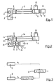
- Fig. 1 is in a tubular measuring cuvette 1 of the optical gas analyzer on the one hand a Meßgas thoroughlyte measuring chamber M and on the other hand arranged with a reference gas reference chamber R for calibration.
- the measuring cuvette 1 is illuminated longitudinally by an infrared radiation source 2 arranged on the light input side. Before the infrared light enters the measuring cuvette 1, this passes through a modulation unit 3 with a rotating chopper disc 4 for phase reversal.
- an opto-pneumatic detector 5 On the light output side of the measuring cuvette 1, an opto-pneumatic detector 5 is placed, which detects the attenuated by absorption losses light beam to produce an electrical signal S 1 for subsequent gas concentration for analysis according to the principle of NDIR spectroscopy. To improve the selectivity in gas mixture analyzes, the opto-pneumatic detector 5 is followed by a broadband receiver 6. In front of the broadband receiver 6, an optical interference filter 7 is arranged. The broadband receiver 6 provided with the optical interference filter 7 serves to generate a second signal S 2 for the elimination of interference by accompanying components in the measurement gas.
- two parallel measuring cuvettes 1 a and 1 b are provided.
- Light output side of a measuring cuvette 1a the opto-pneumatic detector 5 is arranged.
- Light output side of the other measuring cuvette 1 b of the broadband receiver 6 is arranged with the upstream optical interference filter 7.
- two infrared radiation sources 2a and 2b are provided, which are each assigned to one of the measuring cuvettes 1a and 1b.
- the electronic By subtracting the second signal S 2 from the first signal S 1, the evaluation unit 8 corrects the first signal S 1 in accordance with the invention with respect to interfering components contained in the measurement gas in order to eliminate the interference components contained in the measurement gas. Specifically, this is done using the following functionality:
- the starting point is a measuring gas containing a mixture of the measuring component, with the concentration (c 1 ) and n interfering components, with the concentrations (c 2 , ... c 1 + n ). is.
- the spectral absorption coefficients of the respective gases are characterized by ⁇ 1 (v).
- the interfering components now cause a cross-sensitivity QE at the opto-pneumatic detector 5: QE ⁇ ⁇ ⁇ 1 ⁇ 2 S OE ⁇ ⁇ 1 - T gas ⁇ ⁇ dv
- S OE here is the spectral sensitivity function of the opto-pneumatic detector 5. This is a complicated function of the optical and thermodynamic properties of the gas filling, the geometric dimensions of the detector 5, and the transmission properties of the sensitive element and can not be analytically represent. However, the correlation between QE and the respective gas concentrations is based on measurements.
- the spectral information contained in transmission spectra T gas of length n of m different mixtures of the measuring and interfering components (representable as nxm matrix T gas ), by a principal component analysis on the information in the direction of fewer k main components, the axes of a new coordinate system, reduced (representable as kxn-matrix P).
- the matrix P is commonly referred to as a "loading matrix”.
- QE for m different mixtures that is a vector of length m
- the k regression coefficients (in vector b) are the weights which minimize the amplitude of the error vector e.
- QE 1 - T gas ⁇ P ⁇ b + e
- T OI P ⁇ b
Landscapes
- Physics & Mathematics (AREA)
- Spectroscopy & Molecular Physics (AREA)
- Health & Medical Sciences (AREA)
- Life Sciences & Earth Sciences (AREA)
- Chemical & Material Sciences (AREA)
- Analytical Chemistry (AREA)
- Biochemistry (AREA)
- General Health & Medical Sciences (AREA)
- General Physics & Mathematics (AREA)
- Immunology (AREA)
- Pathology (AREA)
- Investigating Or Analysing Materials By Optical Means (AREA)
Abstract
Description
- Die Erfindung betrifft eine optische Gasanalysatoreinrichtung, umfassend mindestens eine in zumindest einer rohrförmigen Messküvette ausgebildete messgasdurchströmte Messkammer, welche mindestens eine eingangsseitig angeordnete infrarote Strahlungsquelle längs durchleuchtet, deren durch Absorptionsverluste abgeschwächter Lichtstrahl mindestens ein ausgangsseitig angeordneten opto-pneumatischen Detektor zur Gaskonzentrationsanalyse nach dem Prinzip der NDIR-Spektroskopie erfasst, wobei optische Mittel zum Verbessern der Selektivität bei Gasgemischanalysen vorgesehen sind.
- Das Einsatzgebiet derartiger Gasanalysatoreinrichtungen, welche nach dem Prinzip der NDIR-Spektroskopie arbeiten, reicht von der Konzentrationsanalyse von Gasen - beispielsweise Kohlenmonoxid oder Kohlendioxid - zur Luftüberwachung bis hin zur Spurenmessung in komplexen Gasgemischen. Gerade hierfür bietet die NDIR-Spektroskopie gegenüber anderen Analyseverfahren, wie der FTIR-Spektroskopie oder der Gaschromatographie, mit wenig messtechnischem Aufwand eine geringe Nachweisgrenze, also Sensitivität.
- Die Gasanalyse mit Hilfe von Gasanalysatoreinrichtungen, welche nach dem Prinzip der nicht-dispersiven Infrarotspektroskopie (NDIR) arbeiten, ist weit gebräuchlich. Der prinzipielle Aufbau einer Gasanalysatoreinrichtung ist stets gleich. Die von der infraroten Strahlungsquelle emittierte Lichtstrahlung durchstrahlt dabei eine das Messgas enthaltene Messküvette und trifft lichtaustrittsseitig auf einen fotoelektrischen Wandler, der meist als ein opto-pneumatischer Detektor ausgebildet ist. Die Erzeugung eines Detektorsignals mit ausreichendem Signal/Rausch-Verhältnis erfordert meist eine Modulation der von der Strahlungsquelle ausgehenden Lichtstrahlung. Auf dem Weg durch die Messküvette wird die von der Strahlungsquelle abgestrahlte Anfangsintensität durch Absorptionsprozesse abgeschwächt. Die Abschwächung hängt über das Lambert-Beer'sche Gesetz mit der Konzentration des absorbierten Gases zusammen.
- Bei der hier interessierenden NDIR-Spektroskopie mit einem opto-pneumatischen Detektor wird gegenüber anderen NDIR-Gasanalysatoreinrichtungen eine besonders hohe Sensitivität und Selektivität erzielt. Diese messtechnisch günstigen Eigenschaften verdankt die Gasanalysatoreinrichtung dem speziellen Detektor, welcher mit der nachzuweisenden Messgaskomponente gefüllt ist. Bei periodischer Bestrahlung mit infrarotem Licht absorbieren die im Detektor enthaltenen Moleküle spezifische Energieanteile, welche über eine Schwingungsrelaxation zu einer Temperatur- und Druckerhöhung des Gases führen. Der opto-pneumatische Detektor ist also nur empfindlich in den Spektralbereichen, die genau den Absorptionsbanden des im Empfänger gespeicherten Gases entsprechen. Deshalb gelten diese NDIR-Gasanalysatoreinrichtungen auch als "Korrelations-Spektrometer", welche prinzipbedingt bereits eine sehr geringe Querempfindlichkeit gegenüber anderen im Messgas enthaltenen Gasen als der Detektorfüllung aufweisen.
- Aus der
DE 39 37 141 A1 geht eine gattungsgemäße optische Gasanalysatoreinrichtung hervor, die nach dem Prinzip der NDIR-Spektroskopie arbeitet. Es werden hier zur gleichzeitigen Messung der Konzentration mehrere Komponenten eines Messgases zwei nebeneinanderliegende Messküvetten verwendet, denen das Messgas bzw. ein Vergleichsgas zugeführt werden und die von modulierten infraroten Lichtstrahlen durchdrungen werden. Nach teilweiser Absorption in den Messküvetten gelangen die Lichtstrahlen auf einem hinter diesen angeordneten ersten opto-pneumatischen Detektor mit zwei in Strahlungsrichtung hintereinander angeordneten Kammern, in welchen eine erste Komponente der Gasprobe enthalten ist. Die beiden Kammern sind durch ein für die infraroten Lichtstrahlen transparentes Fenster getrennt. Ein baugleicher zweiter opto-pneumatischer Detektor ist hinter dem besagten ersten Detektor angeordnet, der mit einer zweiten Komponente der Gasprobe gefüllt ist. Zwischen dem ersten und dem zweiten Detektor ist ein spezieller Strahlungsfilter eingesetzt mit einer Transparenz für die Lichtstrahlen im Bereich schwächerer Strahlungsabsorption der zweiten Komponente der Gasprobe. - Hierdurch kann eine gleichzeitige Messung der Störkomponenten über den zweiten Detektor und anschließend eine rechnerische Korrektur der Querempfindlichkeiten durchgeführt werden. Für die Einbeziehung des zweiten opto-pneumatischen Detektors fällt jedoch ein entsprechend höherer Herstellungsaufwand an. Außerdem steigt der Betriebsaufwand durch die notwendige Wartung der zusätzlichen Messkanäle. Einschränkungen ergeben sich auch dadurch, dass die maximale Anzahl der Detektoren auf vier limitiert ist und viele Kombinationen von Detektoren durch notwendige optische Interferenzfilter vor den Detektoren nicht möglich sind.
- Aus der
DE 10 2004 031 643 A1 geht eine andere optische Gasanalysatoreinrichtung hervor, welche denselben Grundaufbau besitzt. Auch hier ist ein erster opto-pneumatischer Detektor mit einer ersten Komponente der Gasprobe gefüllt und ein hinter diesem angeordneter zweiter opto-pneumatischer Detektor ist mit der zweiten Komponente der Gasprobe gefüllt. Um die Querempfindlichkeit dieser Detektoranordnung zu verringern, wird vorgeschlagen, dass durch Einbau eines Gasfilters vor der Detektoreinrichtung diejenigen Strahlungsanteile vorabsorbiert werden, welche Störkomponenten absorbieren könnten. - Die
DE 197 35 716 A1 offenbart eine andere technische Lösung für die Signalverarbeitung einer Mehrkomponentenmessung mit einer nach dem Prinzip der NDIR-Spektroskopie arbeitenden Gasanalysatoreinrichtung, welche mit nur einem opto-pneumatischen Detektor auskommt. Hierfür wird die Gasanalysatoreinrichtung auf die Erfassung mindestens zweier verschiedener Gaskomponenten sensitiv eingestellt, indem die Kammerverhältnisse und die Füllkonzentration des Detektors derart gewählt oder eingestellt werden, dass zwischen den Signalen der einzelnen Gaskomponenten eine Phasenverschiebung entsteht, die so bemessen wird, dass in einem verwendeten Zeitfenster der Signalauswertung das Integral des Wechselsignals bezüglich der jeweils einen zu messenden Gaskomponente maximal ist und das Integral der anderen Gaskomponente Null oder nahe Null ist. Hiermit wird eine Orthogonalisierung der Signalphasen für Mess- und Störkomponenten erreicht. - Zur Verringerung der Querempfindlichkeit bei Messungen mit opto-pneumatischen Detektoren sind aus dem allgemeinen Stand der Technik ferner Lösungen bekannt, die auf einer Ausblendung von Spektralbereichen mit überlappenden Absorptionen durch Einbau eines optischen Interferenzfilters vor dem opto-pneumatischen Detektor basieren. Weiterhin ist es bekannt, einen opto-pneumatischen Detektor als einen sogenannten Zweischicht-Empfänger mit zwei gasgefüllten hintereinander angeordneten Empfängerkammern aufzubauen, welche beide von der gleichen Strahlung durchstrahlt werden, aber gegenläufig auf das sensitive Element im Detektor wirken, der als Membrankondensator oder Mikroströmungsfühler ausgebildet sein kann. Ferner wird alternativ auch von einer sogenannten optischen Verlängerung der hinteren Detektorkammern bei solchen Zweischicht-Empfängern mit eines mehr oder minder reflektierenden Spiegels hinter den Detektoren Gebrauch gemacht, um die Querempfindlichkeit zu verringern.
- Durch die vorstehend aufgeführten Lösungen kann allerdings die Selektivität immer nur gezielt für eine Störkomponente optimiert werden. Zudem gelingt eine vollständige Eliminierung der Querempfindlichkeitseinflüsse nur für eine spezielle Konzentration der jeweiligen Störkomponente. Es verbleiben also stets Restfehler, die umso größer sind, je mehr Störkomponenten die Messung beeinflussen.
- Es ist daher die Aufgabe der vorliegenden Erfindung, eine optische Gasanalysatoreinrichtung mit Mitteln zum Verbessern der Selektivität bei Gasgemischanalysen zu schaffen, welche einfach aufgebaut sind und bei der Analyse von Gasgemischen mit multiplen Begleitkomponenten eingesetzt werden können, welche im Empfängersignal Querempfindlichkeiten hervorrufen.
- Die Aufgabe wird ausgehend von einer optischen Gasanalysatoreinrichtung gemäß dem Oberbegriff von Anspruch 1 in Verbindung mit dessen kennzeichnenden Merkmalen gelöst. Die nachfolgenden abhängigen Ansprüche geben vorteilhafte Weiterbildungen der Erfindung wieder.
- Die Erfindung schließt die technische Lehre ein, dass die optischen Mittel zur Verbesserung der Selektivität einen zusätzlichen Breitbandempfänger mit einem vorgeschalteten optischen Interferenzfilter umfassen, welcher in Ergänzung zum opto-pneumatischen Detektor zum Einsatz kommt, um die herrschenden Störeinflüsse durch Begleitkomponenten im Messgas zu unterdrücken.
- Mit anderen Worten wird bei der Erfindung ein komplexes optisches Interferenzfilter zusammen mit einem spektralbreitbandig empfindlichen Detektor neben dem bisher üblichen opto-pneumatischen Detektor bei einer gattungsgemäßen Gasanalysatoreinrichtung eingesetzt. Der opto-pneumatische Detektor garantiert hierbei eine hohe Sensitivität bezüglich der Messkomponente; die zusätzlichen optischen Komponenten sind für eine hohe Unterdrückung der Störeinflüsse durch Begleitkomponenten im Messgas vorgesehen.
- Das erfindungsgemäß vorgesehene optische Interferenzfilter ist vorzugsweise als ein mehrere Durchlassbereiche aufweisendes sogenanntes Multivariate Optical Element (MOE) ausgebildet. Das optische Interferenzfilter ist somit nicht nur auf einen einzigen Durchlassbereich beschränkt. Die mehreren Durchlassbereiche des Interferenzfilters sind jeweils einzeln gezielt derart optimiert, dass eine Gewichtung der Strahlungsanteile nach einem vorher bestimmten Muster möglich ist. Ein derartiges Muster kann beispielsweise der gewünschten Durchlasskurve entsprechen.
- Als Breitbandempfänger kommt vorzugsweise ein pyroelektrischer Detektor zur Anwendung. Alternativ hierzu ist es jedoch auch möglich, durch spezielle Gasfüllungen künstlich spektralbreitbandig empfindlich gemachte opto-pneumatische Detektoren zu verwenden. Es sind jedoch auch andere pyroelektrische Detektoren basierend auf der Grundlage des pyroelektrischen Effekts möglich. Die Detektoren bestehen aus ferroelektrischen Kristallen oder Keramiken mit unsymmetrischem Kristallaufbau. Aufgrund dieser Unsymmetrie besitzen solche Materialien ein elektrisches Dipolmoment und damit eine permanente Polarisation. Bei Erwärmung dieser Materialien durch infrarote Strahlung verändern sich die Abstände im Kristallgitter und damit auch die Dipolmomente und die Polarisation. Hierdurch entstehen Ladungen auf der Oberfläche, die als elektrisches Signal abgegriffen werden können. Dieses elektrische Signal ist proportional zur Änderung der Strahlungseinleitung. Vorrangig wird als Grundmaterial für pyroelektrische Detektoren dotiertes Triglycinsulfat (DTGS) verwendet. Ein solcher DTGS-Detektor ist mit einem sehr großen Frequenzbereich einsetzbar, ist einfach aufgebaut und besitzt schnelle Ansprechzeiten, so dass dieser für den erfindungsgegenständlichen Breitbandempfänger besonders geeignet ist. Alternativ hierzu ist es jedoch auch möglich durch spezielle Gasfüllungen künstlich spektralbreitbandig empfindlich gemachte opto-pneumatische Detektoren zu verwenden.
- Gemäß einer weiteren die Erfindung verbessernden Maßnahme die spezielle Signalverarbeitung der erfindungsgemäßen Gasanalysatoreinrichtung betrifft, wird vorgeschlagen, dass ein vom opto-pneumatischen Detektor ausgegebenes, der Erfassung der zu messenden Gaskomponente dienendes erstes Signal S1 und ein vom Breitbandempfänger ausgegebenes, proportional zur gemessenen Querempfindlichkeit am opto-pneumatischen Detektor ausgebildetes zweites Signal S2 eingangsseitig an eine elektronische Auswerteeinheit zur Korrektur des ersten Signals S1 mit Hilfe des zweiten Signals S2 geleitet sind. Im Prinzip kann diese Korrektur durch Subtraktion des zweiten Signals S2 vom ersten Signal S1 erfolgen. Erfasst beispielsweise der opto-pneumatische Detektor das Messgas Kohlenmonoxid als erstes Signal S1, so wird über den Breitbandempfänger, welcher über das vorgeschaltete optische Interferenzfilter spektral selektiv gemacht wird, das zweite Signal S2 auf diese Weise zur Korrektur erzeugt. Durch Tests konnte nachgewiesen werden, dass diese Signalverarbeitung zu hochwertigen Messergebnissen selbst bei hochkomplexen Gasgemischen führt. Dabei kann die erforderliche Signalverarbeitung der Signale S1 und S2 relativ einfach durchgeführt werden.
- In der Praxis ist zu berücksichtigen, dass unter Umständen die charakteristischen Absorptionen der Störkomponenten bei Verwendung der für die Messung von Spuren des Messgases notwendigen langen Messküvetten so stark werden, dass aufgrund der mathematischen Zusammenhänge nicht-lineare Absorptionseffekte auftreten, welche das Messergebnis stark verfälschen würden. Um diesen Fehler auszuschließen, wird gemäß einer speziellen Ausführungsform der optischen Gasanalysatoreinrichtung der Breitbandempfänger mit dem vorgeschalteten optischen Interferenzfilter auf einen zweiten Strahlengang gebaut, der neben einem ersten Strahlengang angeordnet ist, welcher dem opto-pneumatischen Detektor zugeordnet ist. Der zweite Strahlengang kann dabei mit einer relativ kürzeren Messküvette bestückt werden. Somit ist der Breitbandempfänger mit vorgeschaltetem optischen Interferenzfilter räumlich neben dem opto-pneumatischen Detektor angeordnet.
- Nach einer anderen und bevorzugten Ausführungsform der optischen Gasanalysatoreinrichtung ist eine einzige Messküvette vorgesehen, an deren lichtausgangsseitigem Ende der Breitbandempfänger mit dem vorgeschalteten optischen Interferenzfilter angeordnet ist, welchem der opto-pneumatische Detektor in Lichtstrahlrichtung folgt. Somit sind der Breitbandempfänger und der opto-pneumatische Detektor hintereinander auf derselben Lichtachse angeordnet.
- Vorzugsweise besitzt die Messküvette bei den beiden vorstehend beschriebenen bevorzugten Ausführungsformen mehrere Kammern. Insoweit ist längs neben der messgasdurchströmten Messkammer M eine mit einem referenzgasgefüllte Referenzkammer R zur Kalibrierung angeordnet.
- Die vorstehend erwähnte Signalverarbeitung lässt sich vorzugsweise softwaretechnisch realisieren, indem die elektronische Auswerteeinheit mit einem Signalverarbeitungsalgorithmus zur Korrektur des ersten Signals S1 des opto-pneumatischen Detektors mit Hilfe des zweiten Signals S2 des Breitbandempfängers betrieben wird. Die Routine des Signalverarbeitungsalgorithmus ist dabei durch entsprechende in der Software hinterlegte Steuerungsbefehle umgesetzt.
- Weitere die Erfindung verbessernde Maßnahmen werden nachstehend gemeinsam mit der Beschreibung zweier bevorzugter Ausführungsbeispiele der Erfindung anhand der Figuren näher dargestellt. Es zeigt:
- Fig. 1
- eine schematische Darstellung einer ersten Ausführungsform der optischen Gasanalysatoreinrichtung mit einer einzigen Messküvette,
- Fig. 2
- eine schematische Darstellung einer zweiten Ausführungsform der optischen Gasanalysatoreinrichtung mit zwei Messküvetten, und
- Fig. 3
- eine Blockschaltbilddarstellung der Signalverarbeitung der gemessenen Signale S1 und S2.
- Gemäß
Fig. 1 ist in einer rohrförmigen Messküvette 1 der optischen Gasanalysatoreinheit zum einen eine messgasdurchströmte Messkammer M und zum anderen eine mit einem Referenzgas gefüllte Referenzkammer R zur Kalibrierung angeordnet. Die Messküvette 1 wird von einer lichteingangsseitig hieran angeordneten infraroten Strahlungsquelle 2 längs durchleuchtet. Bevor das infrarote Licht in die Messküvette 1 gelangt, passiert dieses eine Modulationseinheit 3 mit rotierender Chopperscheibe 4 zur Phasenumkehr. - Lichtausgangsseitig der Messküvette 1 ist ein opto-pneumatischer Detektor 5 platziert, der den durch Absorptionsverluste abgeschwächten Lichtstrahl erfasst, um ein elektrisches Signal S1 zur nachfolgenden Gaskonzentration zur Analyse nach dem Prinzip der NDIR-Spektroskopie zu erzeugen. Zum Verbessern der Selektivität bei Gasgemischanalysen ist dem opto-pneumatischen Detektor 5 ein Breitbandempfänger 6 nachgeschaltet. Vor dem Breitbandempfänger 6 ist ein optisches Interferenzfilter 7 angeordnet. Der mit dem optischen Interferenzfilter 7 versehene Breitbandempfänger 6 dient zur Erzeugung eines zweiten Signals S2 zur Eliminierung von Störeinflüssen durch Begleitkomponenten im Messgas.
- Gemäß der in
Fig. 2 dargestellten zweiten Ausführungsform sind zwei parallele Messküvetten 1 a und 1 b vorgesehen. Lichtausgangsseitig der einen Messküvette 1a ist der opto-pneumatische Detektor 5 angeordnet. Lichtausgangsseitig der anderen Messküvette 1 b ist der Breitbandempfänger 6 mit dem vorgeschalteten optischen Interferenzfilter 7 angeordnet. In Konsequenz hieraus sind zwei infrarote Strahlungsquellen 2a und 2b vorgesehen, welche jeweils einer der Messküvetten 1a bzw. 1 b zugeordnet sind. - Gemäß
Fig. 3 gelangt das vom opto-pneumatischen Detektor 5 ausgegebene, der Erfassung der zu messenden Gaskomponente dienende Signal S1 und ein vom Breitbandempfänger 6 ausgegebenes, proportional zur gemessenen Querempfindlichkeit am opto-pneumatischen Detektor 5 ausgebildetes Signal S2 eingangsseitig an eine elektronische Auswerteeinheit 8. Die elektronische Auswerteeinheit 8 nimmt durch Subtraktion des zweiten Signals S2 vom ersten Signal S1 eine Korrektur des ersten Signals S1 im erfindungsgemäßen Sinne hinsichtlich im Messgas enthaltener Störkomponenten vor, um die im Messgas enthaltenen Störkomponenten zu eliminieren. Im Einzelnen erfolgt dies anhand der nachfolgend erläuterten Funktionsweise: - Ausgegangen wird von einem Messgas, das ein Gemisch aus der Messkomponente, mit der Konzentration (c1), und n Störkomponenten, mit den Konzentrationen (c2,...c1+n). ist. Die spektralen Absorptionskoeffizienten der jeweiligen Gase seien durch α1(v) gekennzeichnet. Die spektrale optische Transmission durch die im Messgas enthaltenen Störkomponenten TGas(v) ist nach dem Lambert-Beerschen Gesetz:

wobei I die Länge der Messküvette 1 in der NDIR-Gasanalysatoreinrichtung ist. Die Störkomponenten rufen nun eine Querempfindlichkeit QE am opto-pneumatischem Detektor 5 hervor:
- SOE ist hier die spektrale Empfindlichkeitsfunktion des opto-pneumatischen Detektors 5. Diese ist eine komplizierte Funktion der optischen und thermodynamischen Eigenschaften der Gasfüllung, der geometrischen Abmessungen des Detektors 5, und der Übertragungseigenschaften des sensitiven Elements und lässt sich nicht analytisch darstellen. Der Zusammenhang zwischen der QE und den jeweiligen Gaskonzentrationen liegt aber aus Messungen vor.
- Der zusätzliche Breitbandempfänger 6 ist in der Lage, die integrale Absorption des Gasgemisches zu messen:

- Wird vor den Breitbandempfänger 6 ein optisches Interferenzfilter 7 mit einer Durchlasskurve TOI(v) eingesetzt, wird die gemessene integrale Absorption zu:

- Das Ziel ist es nun, TOI so zu definieren, dass A'=QE wird. Dieses gelingt, indem das Interferenzfilter 7 über eine multivariate Datenanalyse spezifisch konzipiert wird.
- Dazu wird die spektrale Information, die in Transmissionspektren TGas der Länge n von m unterschiedlichen Mischungen der Mess- und Störkomponenten enthalten ist (darstellbar als nxm-Matrix TGas), durch eine Hauptkomponentenanalyse auf die Information in Richtung weniger k Hauptkomponenten, die die Achsen eines neuen Koordinatensystems bilden, reduziert (darstellbar als kxn-Matrix P). Die Matrix P wird gewöhnlich auch als "loading matrix" bezeichnet. Der Zusammenhang zwischen QE (für m unterschiedliche Mischungen ist das ein Vektor der Länge m) und den Koordinaten in Richtung der Hauptkomponenten wird über eine Regressionsanalyse (principal component regression, PCR) hergestellt. Die k Regressionskoeffizienten (im Vektor b) sind hierbei diejenigen Gewichte, welche die Amplitude des Fehlervektors e minimieren.

- TOI, als Vektor mit der gleichen Länge n wie die Spektren der Gasmischungen, ergibt sich damit aus:

- Die Erfindung ist nicht beschränkt auf die vorstehend beschriebenen bevorzugten Ausführungsbeispiele. Es sind auch Abwandlungen hiervon denkbar, die vom Schutzbereich der nachfolgenden Ansprüche mit umfasst sind. So ist es beispielsweise auch möglich, Messküvetten ohne Referenzkammer R zu verwenden, sofern die Kalibrierung der Gasanalysatoreinrichtung auf eine andere Weise durchgeführt wird.
-
- 1
- Messküvette
- 2
- Strahlungsquelle
- 3
- Modulationseinheit
- 4
- Shopperscheibe
- 5
- opto-pneumatischer Detektor
- 6
- Breitbandempfänger
- 7
- optisches Interferenzfilter
- 8
- elektronische Auswerteeinheit
Claims (11)
- Optische Gasanalysatoreinrichtung, umfassend mindestens eine in zumindest einer rohrförmigen Messküvette (1; 1 a, 1 b) ausgebildeten messgasdurchströmten Messkammer (M), welche mindestens eine eingangsseitig angeordnete infrarote Strahlungsquelle (2; 2a, 2b) längs durchleuchtet, deren durch Absorptionsverluste abgeschwächter Lichtstrahl mindestens ein ausgangsseitig angeordneter opto-pneumatischer Detektor (5) zur Gaskonzentrationsanalyse nach dem Prinzip der NDIR-Spektroskopie erfasst, wobei optische Mittel zum Verbessern der Selektivität bei Gasgemischanalysen vorgesehen sind,
dadurch gekennzeichnet, dass die optischen Mittel zum Verbessern der Selektivität einen Breitbandempfänger (6) mit einem vorgeschalteten optischen Interferenzfilter (7) umfassen, der zusätzlich zum opto-pneumatischer Detektor (5) zum Einsatz kommt, um Störeinflüsse durch Begleitkomponenten im Messgas zu unterdrücken. - Optische Gasanalysatoreinrichtung nach Anspruch 1,
dadurch gekennzeichnet, dass das optischen Interferenzfilter (7) als ein mehrere Durchlassbereiche aufweisendes Multivariate Optical Element (MOE) ausgebildet ist. - Optische Gasanalysatoreinrichtung nach Anspruch 1,
dadurch gekennzeichnet, dass der Breitbandempfänger (6) als ein pyroelektrischer Detektor ausgebildet ist. - Optische Gasanalysatoreinrichtung nach Anspruch 1,
dadurch gekennzeichnet, dass ein vom opto-pneumatischen Detektor () ausgegebenes, der Erfassung der zu messenden Gaskomponente dienendes erstes Signal (S1) und ein vom Breitbandempfänger () ausgegebenes, proportional zur gemessenen Querempfindlichkeit am opto-pneumatischen Detektor () ausgebildetes zweites Signal (S2) eingangsseitig an eine elektronische Auswerteeinheit (8) zur Korrektur des ersten Signals (S1) mit Hilfe des zweiten Signals (S2) geleitet sind. - Optische Gasanalysatoreinrichtung nach Anspruch 1,
dadurch gekennzeichnet, dass die mindestens eine Messküvette (1; 1a, 1 b) längs neben der messgasdurchströmten Messkammer (M) eine mit einem Referenzgas gefüllte Referenzkammer (R) zur Kalibrierung aufweist. - Optische Gasanalysatoreinrichtung nach Anspruch 5,
dadurch gekennzeichnet, dass eine einzige Messküvette (1) vorgesehen ist, an deren lichtausgangsseitigem Ende der opto-pneumatische Detektor (5) angeordnet ist, welchem der Breitbandempfänger (6) mit dem vorgeschalteten optischen Interferenzfilter (7) in Lichtstrahlrichtung folgt. - Optische Gasanalysatoreinrichtung nach Anspruch 5,
dadurch gekennzeichnet, dass zwei parallele Messküvetten (1a, 1 b) vorgesehen sind, wobei lichtausgangsseitig an der einen Messküvette (1a) der opto-pneumatische Detektor (5) angeordnet ist, wogegen lichtausgangsseitig an der anderen Messküvette (1 b) der Breitbandempfänger (6) mit dem vorgeschalteten optischen Interferenzfilter (7) angeordnet ist. - Optische Gasanalysatoreinrichtung nach Anspruch 1,
dadurch gekennzeichnet, dass die eine Messküvette (1a) länger als die andere Messküvette (1b) ausgebildet ist. - Optische Gasanalysatoreinrichtung nach Anspruch 1,
dadurch gekennzeichnet, dass die lichteingangsseitig der mindestens einen Messküvette (1; 1a, 1 b) angeordnete infrarote Strahlungsquelle (2) eine Modulationseinheit (3) mit rotierender Chopperscheibe (4) zur Phasenumkehr aufweist. - Computerprogrammprodukt für eine Gasanalysatoreinrichtung nach einem der Ansprüche 1 bis 9, deren elektronische Auswerteeinheit (8) mit einem Signalverarbeitungsalgorithmus zur Korrektur des ersten Signals (S1) des opto-pneumatischen Detektor (5) mit Hilfe des zweiten Signals (S2) des Breitbandempfängers (6) betreibbar ist, wobei die Routine des Signalverarbeitungsalgorithmus durch entsprechende in einer Software hinterlegte Steuerungsbefehle umgesetzt ist.
- Datenträger mit einem Computerprogrammprodukt nach Anspruch 10.
Applications Claiming Priority (1)
| Application Number | Priority Date | Filing Date | Title |
|---|---|---|---|
| DE102011108941A DE102011108941B4 (de) | 2011-07-29 | 2011-07-29 | Optische Gasanalysatoreinrichtung mit Mitteln zum Verbessern der Selektivität bei Gasgemischanalysen |
Publications (2)
| Publication Number | Publication Date |
|---|---|
| EP2551662A1 true EP2551662A1 (de) | 2013-01-30 |
| EP2551662B1 EP2551662B1 (de) | 2020-09-02 |
Family
ID=46679056
Family Applications (1)
| Application Number | Title | Priority Date | Filing Date |
|---|---|---|---|
| EP12005326.9A Not-in-force EP2551662B1 (de) | 2011-07-29 | 2012-07-20 | Optische Gasanalysatoreinrichtung mit Mitteln zum Verbessern der Selektivität bei Gasgemischanalysen |
Country Status (3)
| Country | Link |
|---|---|
| EP (1) | EP2551662B1 (de) |
| CN (1) | CN102980871B (de) |
| DE (1) | DE102011108941B4 (de) |
Cited By (2)
| Publication number | Priority date | Publication date | Assignee | Title |
|---|---|---|---|---|
| WO2019037648A1 (zh) | 2017-08-21 | 2019-02-28 | 湖北锐意自控系统有限公司 | 一种气体分析仪及气体分析方法 |
| US20200163314A1 (en) * | 2017-07-23 | 2020-05-28 | Terahertz Group Ltd. | System and method for non-invasively determining egg properties |
Families Citing this family (2)
| Publication number | Priority date | Publication date | Assignee | Title |
|---|---|---|---|---|
| DE102013113170A1 (de) * | 2013-11-28 | 2015-05-28 | Endress + Hauser Conducta Gesellschaft für Mess- und Regeltechnik mbH + Co. KG | Verfahren zur Bestimmung eines Messwerts und Analysator zur Ausführung des Verfahrens |
| CN112033925B (zh) * | 2020-09-02 | 2025-08-15 | 四方光电(武汉)仪器有限公司 | 一种多组分宽量程气体分析仪及气体分析方法 |
Citations (3)
| Publication number | Priority date | Publication date | Assignee | Title |
|---|---|---|---|---|
| US4355233A (en) * | 1979-02-22 | 1982-10-19 | Beckman Instruments, Inc. | Method and apparatus for negating measurement effects of interferent gases in non-dispersive infrared analyzers |
| DE19735716A1 (de) | 1997-07-05 | 1999-02-04 | Hartmann & Braun Gmbh & Co Kg | Mehrkomponentenmessung mit einem nichtdispersiven Infrarotspektrometer |
| DE102004031643A1 (de) | 2004-06-30 | 2006-02-02 | Abb Patent Gmbh | Nichtdispersiver Infrarot-Gasanalysator |
Family Cites Families (5)
| Publication number | Priority date | Publication date | Assignee | Title |
|---|---|---|---|---|
| DE3321360A1 (de) * | 1983-06-14 | 1984-12-20 | Hartmann & Braun Ag, 6000 Frankfurt | Nichtdispersiver infrarot-gasanalysator |
| DE3446436A1 (de) * | 1984-12-20 | 1986-07-03 | Hartmann & Braun Ag, 6000 Frankfurt | Nichtdispersives fotometer |
| DE3937141A1 (de) * | 1989-11-08 | 1991-05-16 | Hartmann & Braun Ag | Nichtdispersiver infrarot-gasanalysator zur gleichzeitigen messung der konzentration mehrerer komponenten einer gasprobe |
| DE10112579C2 (de) * | 2001-03-15 | 2003-02-13 | Siemens Ag | Infrarot-Gasanalysator |
| US20080277586A1 (en) * | 2007-05-07 | 2008-11-13 | Dennis Cardinale | Low-Power Fast Infrared Gas Sensor, Hand Held Gas Leak Detector, and Gas Monitor Utilizing Absorptive-Photo-Acoustic Detection |
-
2011
- 2011-07-29 DE DE102011108941A patent/DE102011108941B4/de not_active Expired - Fee Related
-
2012
- 2012-07-20 EP EP12005326.9A patent/EP2551662B1/de not_active Not-in-force
- 2012-07-27 CN CN201210434456.XA patent/CN102980871B/zh not_active Expired - Fee Related
Patent Citations (3)
| Publication number | Priority date | Publication date | Assignee | Title |
|---|---|---|---|---|
| US4355233A (en) * | 1979-02-22 | 1982-10-19 | Beckman Instruments, Inc. | Method and apparatus for negating measurement effects of interferent gases in non-dispersive infrared analyzers |
| DE19735716A1 (de) | 1997-07-05 | 1999-02-04 | Hartmann & Braun Gmbh & Co Kg | Mehrkomponentenmessung mit einem nichtdispersiven Infrarotspektrometer |
| DE102004031643A1 (de) | 2004-06-30 | 2006-02-02 | Abb Patent Gmbh | Nichtdispersiver Infrarot-Gasanalysator |
Cited By (5)
| Publication number | Priority date | Publication date | Assignee | Title |
|---|---|---|---|---|
| US20200163314A1 (en) * | 2017-07-23 | 2020-05-28 | Terahertz Group Ltd. | System and method for non-invasively determining egg properties |
| US12082561B2 (en) * | 2017-07-23 | 2024-09-10 | Terahertz Group Ltd. | System and method for non-invasively determining egg properties |
| WO2019037648A1 (zh) | 2017-08-21 | 2019-02-28 | 湖北锐意自控系统有限公司 | 一种气体分析仪及气体分析方法 |
| EP3674689A4 (de) * | 2017-08-21 | 2021-07-28 | Hubei Cubic-ruiyi Instrument Co., Ltd | Gasanalysator und gasanalyseverfahren |
| US11079322B2 (en) * | 2017-08-21 | 2021-08-03 | Hubei Cubic-Ruiyi Instrument Co., Ltd | Gas analyzer and gas analyzing method |
Also Published As
| Publication number | Publication date |
|---|---|
| CN102980871B (zh) | 2017-03-01 |
| DE102011108941B4 (de) | 2013-02-28 |
| DE102011108941A1 (de) | 2013-01-31 |
| CN102980871A (zh) | 2013-03-20 |
| EP2551662B1 (de) | 2020-09-02 |
Similar Documents
| Publication | Publication Date | Title |
|---|---|---|
| EP0076356B1 (de) | Verfahren und Vorrichtung zur Messung der Konzentration einer IR-, NDIR-, VIS- oder UV-Strahlung absorbierenden Komponente eines Komponentengemischs | |
| EP0426982A2 (de) | Abgleichverfahren für einen nichtdispersiven Infrarot-Gasanalysator | |
| EP2956758B1 (de) | Verfahren und vorrichtung zur bestimmung einer konzentration einer fluoreszierenden substanz in einem medium | |
| DE3937141A1 (de) | Nichtdispersiver infrarot-gasanalysator zur gleichzeitigen messung der konzentration mehrerer komponenten einer gasprobe | |
| EP2551662B1 (de) | Optische Gasanalysatoreinrichtung mit Mitteln zum Verbessern der Selektivität bei Gasgemischanalysen | |
| DE19509822C2 (de) | Ölkonzentrations-Meßgerät | |
| DE102009059962A1 (de) | NDIR-Zweistrahl-Gasanalysator und Verfahren zur Bestimmung der Konzentration einer Messgaskomponente in einem Gasgemisch mittels eines solchen Gasanalysators | |
| DE3938142C2 (de) | ||
| DE102004031643A1 (de) | Nichtdispersiver Infrarot-Gasanalysator | |
| DE102016108545B4 (de) | NDIR-Gassensor und Verfahren zu dessen Kalibrierung | |
| DE2927156A1 (de) | Vorrichtung zum messen der sauerstoffkonzentration | |
| WO1999009391A2 (de) | Ndir-fotometer zur mehrkomponentenmessung | |
| EP0087077A2 (de) | Messeinrichtung für die optische Gasanalyse | |
| DE102007020596A1 (de) | Detektoranordnung für einen nichtdispersiven Infrarot-Gasanalysator | |
| DE3544015C2 (de) | ||
| EP0076886A1 (de) | Verfahren und Vorrichtung zur Messung des Konzentrations-verhältnisses zweier IR-, NIR-, VIS- oder UV-Strahlung absorbierender Komponenten eines Komponentengemischs | |
| DE102011109000B4 (de) | Optische Gasanalysatoreinrichtung mit Mitteln zumVerbessern des Dynamikbereichs der Messung | |
| DE3446436C2 (de) | ||
| EP3575759B1 (de) | Spektrometer und verfahren zum betrieb | |
| EP1621868A1 (de) | Einrichtung und Verfahren zur Kalibrierung der Empfindlichkeit eines Fotometers | |
| EP2585810A1 (de) | Nichtdispersiver gasanalysator | |
| EP0898164B1 (de) | Verfahren und Einrichtung zur Unterdrückung der N2O Querempfindlichkeit zu CO2 bei NDIR-Fotometern | |
| DE2751010A1 (de) | Verfahren und vorrichtung zur korrektur von hintergrundsstrahlung bei spektrochemischen analysen biologischer proben | |
| DE102023207914A1 (de) | Terahertz-Gasspektroskopie-Vorrichtung | |
| DE19752508A1 (de) | NDIR-Fotometer zur Mehrkomponentenmessung |
Legal Events
| Date | Code | Title | Description |
|---|---|---|---|
| PUAI | Public reference made under article 153(3) epc to a published international application that has entered the european phase |
Free format text: ORIGINAL CODE: 0009012 |
|
| AK | Designated contracting states |
Kind code of ref document: A1 Designated state(s): AL AT BE BG CH CY CZ DE DK EE ES FI FR GB GR HR HU IE IS IT LI LT LU LV MC MK MT NL NO PL PT RO RS SE SI SK SM TR |
|
| AX | Request for extension of the european patent |
Extension state: BA ME |
|
| 17P | Request for examination filed |
Effective date: 20130730 |
|
| RBV | Designated contracting states (corrected) |
Designated state(s): AL AT BE BG CH CY CZ DE DK EE ES FI FR GB GR HR HU IE IS IT LI LT LU LV MC MK MT NL NO PL PT RO RS SE SI SK SM TR |
|
| RAP1 | Party data changed (applicant data changed or rights of an application transferred) |
Owner name: ABB SCHWEIZ AG |
|
| GRAP | Despatch of communication of intention to grant a patent |
Free format text: ORIGINAL CODE: EPIDOSNIGR1 |
|
| STAA | Information on the status of an ep patent application or granted ep patent |
Free format text: STATUS: GRANT OF PATENT IS INTENDED |
|
| INTG | Intention to grant announced |
Effective date: 20200212 |
|
| GRAS | Grant fee paid |
Free format text: ORIGINAL CODE: EPIDOSNIGR3 |
|
| RIN1 | Information on inventor provided before grant (corrected) |
Inventor name: KAPPLER, JUERGEN, DR. Inventor name: RATHKE, CARSTEN, DR. |
|
| GRAA | (expected) grant |
Free format text: ORIGINAL CODE: 0009210 |
|
| STAA | Information on the status of an ep patent application or granted ep patent |
Free format text: STATUS: THE PATENT HAS BEEN GRANTED |
|
| AK | Designated contracting states |
Kind code of ref document: B1 Designated state(s): AL AT BE BG CH CY CZ DE DK EE ES FI FR GB GR HR HU IE IS IT LI LT LU LV MC MK MT NL NO PL PT RO RS SE SI SK SM TR |
|
| REG | Reference to a national code |
Ref country code: GB Ref legal event code: FG4D Free format text: NOT ENGLISH |
|
| REG | Reference to a national code |
Ref country code: AT Ref legal event code: REF Ref document number: 1309408 Country of ref document: AT Kind code of ref document: T Effective date: 20200915 Ref country code: CH Ref legal event code: EP |
|
| REG | Reference to a national code |
Ref country code: DE Ref legal event code: R096 Ref document number: 502012016325 Country of ref document: DE |
|
| REG | Reference to a national code |
Ref country code: IE Ref legal event code: FG4D Free format text: LANGUAGE OF EP DOCUMENT: GERMAN |
|
| RAP2 | Party data changed (patent owner data changed or rights of a patent transferred) |
Owner name: ABB SCHWEIZ AG |
|
| REG | Reference to a national code |
Ref country code: LT Ref legal event code: MG4D |
|
| PG25 | Lapsed in a contracting state [announced via postgrant information from national office to epo] |
Ref country code: HR Free format text: LAPSE BECAUSE OF FAILURE TO SUBMIT A TRANSLATION OF THE DESCRIPTION OR TO PAY THE FEE WITHIN THE PRESCRIBED TIME-LIMIT Effective date: 20200902 Ref country code: LT Free format text: LAPSE BECAUSE OF FAILURE TO SUBMIT A TRANSLATION OF THE DESCRIPTION OR TO PAY THE FEE WITHIN THE PRESCRIBED TIME-LIMIT Effective date: 20200902 Ref country code: BG Free format text: LAPSE BECAUSE OF FAILURE TO SUBMIT A TRANSLATION OF THE DESCRIPTION OR TO PAY THE FEE WITHIN THE PRESCRIBED TIME-LIMIT Effective date: 20201202 Ref country code: SE Free format text: LAPSE BECAUSE OF FAILURE TO SUBMIT A TRANSLATION OF THE DESCRIPTION OR TO PAY THE FEE WITHIN THE PRESCRIBED TIME-LIMIT Effective date: 20200902 Ref country code: NO Free format text: LAPSE BECAUSE OF FAILURE TO SUBMIT A TRANSLATION OF THE DESCRIPTION OR TO PAY THE FEE WITHIN THE PRESCRIBED TIME-LIMIT Effective date: 20201202 Ref country code: GR Free format text: LAPSE BECAUSE OF FAILURE TO SUBMIT A TRANSLATION OF THE DESCRIPTION OR TO PAY THE FEE WITHIN THE PRESCRIBED TIME-LIMIT Effective date: 20201203 Ref country code: FI Free format text: LAPSE BECAUSE OF FAILURE TO SUBMIT A TRANSLATION OF THE DESCRIPTION OR TO PAY THE FEE WITHIN THE PRESCRIBED TIME-LIMIT Effective date: 20200902 |
|
| REG | Reference to a national code |
Ref country code: NL Ref legal event code: MP Effective date: 20200902 |
|
| PG25 | Lapsed in a contracting state [announced via postgrant information from national office to epo] |
Ref country code: RS Free format text: LAPSE BECAUSE OF FAILURE TO SUBMIT A TRANSLATION OF THE DESCRIPTION OR TO PAY THE FEE WITHIN THE PRESCRIBED TIME-LIMIT Effective date: 20200902 Ref country code: LV Free format text: LAPSE BECAUSE OF FAILURE TO SUBMIT A TRANSLATION OF THE DESCRIPTION OR TO PAY THE FEE WITHIN THE PRESCRIBED TIME-LIMIT Effective date: 20200902 Ref country code: PL Free format text: LAPSE BECAUSE OF FAILURE TO SUBMIT A TRANSLATION OF THE DESCRIPTION OR TO PAY THE FEE WITHIN THE PRESCRIBED TIME-LIMIT Effective date: 20200902 |
|
| PG25 | Lapsed in a contracting state [announced via postgrant information from national office to epo] |
Ref country code: CZ Free format text: LAPSE BECAUSE OF FAILURE TO SUBMIT A TRANSLATION OF THE DESCRIPTION OR TO PAY THE FEE WITHIN THE PRESCRIBED TIME-LIMIT Effective date: 20200902 Ref country code: EE Free format text: LAPSE BECAUSE OF FAILURE TO SUBMIT A TRANSLATION OF THE DESCRIPTION OR TO PAY THE FEE WITHIN THE PRESCRIBED TIME-LIMIT Effective date: 20200902 Ref country code: SM Free format text: LAPSE BECAUSE OF FAILURE TO SUBMIT A TRANSLATION OF THE DESCRIPTION OR TO PAY THE FEE WITHIN THE PRESCRIBED TIME-LIMIT Effective date: 20200902 Ref country code: RO Free format text: LAPSE BECAUSE OF FAILURE TO SUBMIT A TRANSLATION OF THE DESCRIPTION OR TO PAY THE FEE WITHIN THE PRESCRIBED TIME-LIMIT Effective date: 20200902 Ref country code: NL Free format text: LAPSE BECAUSE OF FAILURE TO SUBMIT A TRANSLATION OF THE DESCRIPTION OR TO PAY THE FEE WITHIN THE PRESCRIBED TIME-LIMIT Effective date: 20200902 Ref country code: PT Free format text: LAPSE BECAUSE OF FAILURE TO SUBMIT A TRANSLATION OF THE DESCRIPTION OR TO PAY THE FEE WITHIN THE PRESCRIBED TIME-LIMIT Effective date: 20210104 |
|
| PG25 | Lapsed in a contracting state [announced via postgrant information from national office to epo] |
Ref country code: IS Free format text: LAPSE BECAUSE OF FAILURE TO SUBMIT A TRANSLATION OF THE DESCRIPTION OR TO PAY THE FEE WITHIN THE PRESCRIBED TIME-LIMIT Effective date: 20210102 Ref country code: ES Free format text: LAPSE BECAUSE OF FAILURE TO SUBMIT A TRANSLATION OF THE DESCRIPTION OR TO PAY THE FEE WITHIN THE PRESCRIBED TIME-LIMIT Effective date: 20200902 Ref country code: AL Free format text: LAPSE BECAUSE OF FAILURE TO SUBMIT A TRANSLATION OF THE DESCRIPTION OR TO PAY THE FEE WITHIN THE PRESCRIBED TIME-LIMIT Effective date: 20200902 |
|
| REG | Reference to a national code |
Ref country code: DE Ref legal event code: R097 Ref document number: 502012016325 Country of ref document: DE |
|
| PG25 | Lapsed in a contracting state [announced via postgrant information from national office to epo] |
Ref country code: SK Free format text: LAPSE BECAUSE OF FAILURE TO SUBMIT A TRANSLATION OF THE DESCRIPTION OR TO PAY THE FEE WITHIN THE PRESCRIBED TIME-LIMIT Effective date: 20200902 |
|
| PLBE | No opposition filed within time limit |
Free format text: ORIGINAL CODE: 0009261 |
|
| STAA | Information on the status of an ep patent application or granted ep patent |
Free format text: STATUS: NO OPPOSITION FILED WITHIN TIME LIMIT |
|
| 26N | No opposition filed |
Effective date: 20210603 |
|
| PG25 | Lapsed in a contracting state [announced via postgrant information from national office to epo] |
Ref country code: DK Free format text: LAPSE BECAUSE OF FAILURE TO SUBMIT A TRANSLATION OF THE DESCRIPTION OR TO PAY THE FEE WITHIN THE PRESCRIBED TIME-LIMIT Effective date: 20200902 Ref country code: SI Free format text: LAPSE BECAUSE OF FAILURE TO SUBMIT A TRANSLATION OF THE DESCRIPTION OR TO PAY THE FEE WITHIN THE PRESCRIBED TIME-LIMIT Effective date: 20200902 |
|
| PG25 | Lapsed in a contracting state [announced via postgrant information from national office to epo] |
Ref country code: IT Free format text: LAPSE BECAUSE OF FAILURE TO SUBMIT A TRANSLATION OF THE DESCRIPTION OR TO PAY THE FEE WITHIN THE PRESCRIBED TIME-LIMIT Effective date: 20200902 |
|
| REG | Reference to a national code |
Ref country code: CH Ref legal event code: PL |
|
| PG25 | Lapsed in a contracting state [announced via postgrant information from national office to epo] |
Ref country code: MC Free format text: LAPSE BECAUSE OF FAILURE TO SUBMIT A TRANSLATION OF THE DESCRIPTION OR TO PAY THE FEE WITHIN THE PRESCRIBED TIME-LIMIT Effective date: 20200902 |
|
| REG | Reference to a national code |
Ref country code: BE Ref legal event code: MM Effective date: 20210731 |
|
| PG25 | Lapsed in a contracting state [announced via postgrant information from national office to epo] |
Ref country code: LI Free format text: LAPSE BECAUSE OF NON-PAYMENT OF DUE FEES Effective date: 20210731 Ref country code: CH Free format text: LAPSE BECAUSE OF NON-PAYMENT OF DUE FEES Effective date: 20210731 |
|
| PG25 | Lapsed in a contracting state [announced via postgrant information from national office to epo] |
Ref country code: LU Free format text: LAPSE BECAUSE OF NON-PAYMENT OF DUE FEES Effective date: 20210720 |
|
| PG25 | Lapsed in a contracting state [announced via postgrant information from national office to epo] |
Ref country code: IE Free format text: LAPSE BECAUSE OF NON-PAYMENT OF DUE FEES Effective date: 20210720 Ref country code: BE Free format text: LAPSE BECAUSE OF NON-PAYMENT OF DUE FEES Effective date: 20210731 |
|
| REG | Reference to a national code |
Ref country code: AT Ref legal event code: MM01 Ref document number: 1309408 Country of ref document: AT Kind code of ref document: T Effective date: 20210720 |
|
| PG25 | Lapsed in a contracting state [announced via postgrant information from national office to epo] |
Ref country code: AT Free format text: LAPSE BECAUSE OF NON-PAYMENT OF DUE FEES Effective date: 20210720 |
|
| PG25 | Lapsed in a contracting state [announced via postgrant information from national office to epo] |
Ref country code: HU Free format text: LAPSE BECAUSE OF FAILURE TO SUBMIT A TRANSLATION OF THE DESCRIPTION OR TO PAY THE FEE WITHIN THE PRESCRIBED TIME-LIMIT; INVALID AB INITIO Effective date: 20120720 Ref country code: CY Free format text: LAPSE BECAUSE OF FAILURE TO SUBMIT A TRANSLATION OF THE DESCRIPTION OR TO PAY THE FEE WITHIN THE PRESCRIBED TIME-LIMIT Effective date: 20200902 |
|
| PGFP | Annual fee paid to national office [announced via postgrant information from national office to epo] |
Ref country code: GB Payment date: 20230720 Year of fee payment: 12 |
|
| PGFP | Annual fee paid to national office [announced via postgrant information from national office to epo] |
Ref country code: FR Payment date: 20230725 Year of fee payment: 12 Ref country code: DE Payment date: 20230719 Year of fee payment: 12 |
|
| PG25 | Lapsed in a contracting state [announced via postgrant information from national office to epo] |
Ref country code: MK Free format text: LAPSE BECAUSE OF FAILURE TO SUBMIT A TRANSLATION OF THE DESCRIPTION OR TO PAY THE FEE WITHIN THE PRESCRIBED TIME-LIMIT Effective date: 20200902 |
|
| PG25 | Lapsed in a contracting state [announced via postgrant information from national office to epo] |
Ref country code: TR Free format text: LAPSE BECAUSE OF FAILURE TO SUBMIT A TRANSLATION OF THE DESCRIPTION OR TO PAY THE FEE WITHIN THE PRESCRIBED TIME-LIMIT Effective date: 20200902 |
|
| PG25 | Lapsed in a contracting state [announced via postgrant information from national office to epo] |
Ref country code: MT Free format text: LAPSE BECAUSE OF FAILURE TO SUBMIT A TRANSLATION OF THE DESCRIPTION OR TO PAY THE FEE WITHIN THE PRESCRIBED TIME-LIMIT Effective date: 20200902 |
|
| REG | Reference to a national code |
Ref country code: DE Ref legal event code: R119 Ref document number: 502012016325 Country of ref document: DE |
|
| GBPC | Gb: european patent ceased through non-payment of renewal fee |
Effective date: 20240720 |
|
| PG25 | Lapsed in a contracting state [announced via postgrant information from national office to epo] |
Ref country code: DE Free format text: LAPSE BECAUSE OF NON-PAYMENT OF DUE FEES Effective date: 20250201 |
|
| PG25 | Lapsed in a contracting state [announced via postgrant information from national office to epo] |
Ref country code: FR Free format text: LAPSE BECAUSE OF NON-PAYMENT OF DUE FEES Effective date: 20240731 |
|
| PG25 | Lapsed in a contracting state [announced via postgrant information from national office to epo] |
Ref country code: GB Free format text: LAPSE BECAUSE OF NON-PAYMENT OF DUE FEES Effective date: 20240720 |