EP2551447A2 - Zusammengesetztes Motorsystem mit Drehmotor - Google Patents
Zusammengesetztes Motorsystem mit Drehmotor Download PDFInfo
- Publication number
- EP2551447A2 EP2551447A2 EP12177792A EP12177792A EP2551447A2 EP 2551447 A2 EP2551447 A2 EP 2551447A2 EP 12177792 A EP12177792 A EP 12177792A EP 12177792 A EP12177792 A EP 12177792A EP 2551447 A2 EP2551447 A2 EP 2551447A2
- Authority
- EP
- European Patent Office
- Prior art keywords
- volume
- rotor
- rotary engine
- engine
- chambers
- Prior art date
- Legal status (The legal status is an assumption and is not a legal conclusion. Google has not performed a legal analysis and makes no representation as to the accuracy of the status listed.)
- Withdrawn
Links
- 150000001875 compounds Chemical class 0.000 title claims abstract description 16
- 230000002093 peripheral effect Effects 0.000 claims abstract description 21
- 230000006835 compression Effects 0.000 claims abstract description 15
- 238000007906 compression Methods 0.000 claims abstract description 15
- 238000006073 displacement reaction Methods 0.000 claims abstract description 14
- 238000002485 combustion reaction Methods 0.000 claims description 12
- 238000000034 method Methods 0.000 claims description 9
- 238000004891 communication Methods 0.000 claims description 8
- 238000004513 sizing Methods 0.000 claims description 6
- 238000007789 sealing Methods 0.000 claims description 4
- 239000000446 fuel Substances 0.000 description 10
- 238000010926 purge Methods 0.000 description 7
- 239000002826 coolant Substances 0.000 description 3
- 238000002347 injection Methods 0.000 description 3
- 239000007924 injection Substances 0.000 description 3
- 239000000203 mixture Substances 0.000 description 3
- 239000003921 oil Substances 0.000 description 3
- 239000003350 kerosene Substances 0.000 description 2
- 238000012986 modification Methods 0.000 description 2
- 230000004048 modification Effects 0.000 description 2
- 239000003570 air Substances 0.000 description 1
- 239000002551 biofuel Substances 0.000 description 1
- 238000001816 cooling Methods 0.000 description 1
- 238000013461 design Methods 0.000 description 1
- 238000010586 diagram Methods 0.000 description 1
- -1 diesel Substances 0.000 description 1
- 230000009977 dual effect Effects 0.000 description 1
- KVIPHDKUOLVVQN-UHFFFAOYSA-N ethene;hydrate Chemical group O.C=C KVIPHDKUOLVVQN-UHFFFAOYSA-N 0.000 description 1
- 239000010687 lubricating oil Substances 0.000 description 1
- 230000001141 propulsive effect Effects 0.000 description 1
- 238000005086 pumping Methods 0.000 description 1
- 238000010791 quenching Methods 0.000 description 1
- 238000012552 review Methods 0.000 description 1
- 239000007921 spray Substances 0.000 description 1
Images

Classifications
-
- F—MECHANICAL ENGINEERING; LIGHTING; HEATING; WEAPONS; BLASTING
- F02—COMBUSTION ENGINES; HOT-GAS OR COMBUSTION-PRODUCT ENGINE PLANTS
- F02B—INTERNAL-COMBUSTION PISTON ENGINES; COMBUSTION ENGINES IN GENERAL
- F02B55/00—Internal-combustion aspects of rotary pistons; Outer members for co-operation with rotary pistons
- F02B55/14—Shapes or constructions of combustion chambers
-
- F—MECHANICAL ENGINEERING; LIGHTING; HEATING; WEAPONS; BLASTING
- F01—MACHINES OR ENGINES IN GENERAL; ENGINE PLANTS IN GENERAL; STEAM ENGINES
- F01C—ROTARY-PISTON OR OSCILLATING-PISTON MACHINES OR ENGINES
- F01C1/00—Rotary-piston machines or engines
- F01C1/22—Rotary-piston machines or engines of internal-axis type with equidirectional movement of co-operating members at the points of engagement, or with one of the co-operating members being stationary, the inner member having more teeth or tooth- equivalents than the outer member
-
- F—MECHANICAL ENGINEERING; LIGHTING; HEATING; WEAPONS; BLASTING
- F01—MACHINES OR ENGINES IN GENERAL; ENGINE PLANTS IN GENERAL; STEAM ENGINES
- F01C—ROTARY-PISTON OR OSCILLATING-PISTON MACHINES OR ENGINES
- F01C11/00—Combinations of two or more machines or engines, each being of rotary-piston or oscillating-piston type
- F01C11/006—Combinations of two or more machines or engines, each being of rotary-piston or oscillating-piston type of dissimilar working principle
-
- F—MECHANICAL ENGINEERING; LIGHTING; HEATING; WEAPONS; BLASTING
- F01—MACHINES OR ENGINES IN GENERAL; ENGINE PLANTS IN GENERAL; STEAM ENGINES
- F01C—ROTARY-PISTON OR OSCILLATING-PISTON MACHINES OR ENGINES
- F01C21/00—Component parts, details or accessories not provided for in groups F01C1/00 - F01C20/00
- F01C21/08—Rotary pistons
-
- F—MECHANICAL ENGINEERING; LIGHTING; HEATING; WEAPONS; BLASTING
- F01—MACHINES OR ENGINES IN GENERAL; ENGINE PLANTS IN GENERAL; STEAM ENGINES
- F01C—ROTARY-PISTON OR OSCILLATING-PISTON MACHINES OR ENGINES
- F01C21/00—Component parts, details or accessories not provided for in groups F01C1/00 - F01C20/00
- F01C21/18—Arrangements for admission or discharge of the working fluid, e.g. constructional features of the inlet or outlet
-
- F—MECHANICAL ENGINEERING; LIGHTING; HEATING; WEAPONS; BLASTING
- F02—COMBUSTION ENGINES; HOT-GAS OR COMBUSTION-PRODUCT ENGINE PLANTS
- F02B—INTERNAL-COMBUSTION PISTON ENGINES; COMBUSTION ENGINES IN GENERAL
- F02B37/00—Engines characterised by provision of pumps driven at least for part of the time by exhaust
-
- F—MECHANICAL ENGINEERING; LIGHTING; HEATING; WEAPONS; BLASTING
- F02—COMBUSTION ENGINES; HOT-GAS OR COMBUSTION-PRODUCT ENGINE PLANTS
- F02B—INTERNAL-COMBUSTION PISTON ENGINES; COMBUSTION ENGINES IN GENERAL
- F02B55/00—Internal-combustion aspects of rotary pistons; Outer members for co-operation with rotary pistons
- F02B55/02—Pistons
-
- F—MECHANICAL ENGINEERING; LIGHTING; HEATING; WEAPONS; BLASTING
- F01—MACHINES OR ENGINES IN GENERAL; ENGINE PLANTS IN GENERAL; STEAM ENGINES
- F01C—ROTARY-PISTON OR OSCILLATING-PISTON MACHINES OR ENGINES
- F01C20/00—Control of, monitoring of, or safety arrangements for, machines or engines
- F01C20/06—Control of, monitoring of, or safety arrangements for, machines or engines specially adapted for stopping, starting, idling or no-load operation
-
- F—MECHANICAL ENGINEERING; LIGHTING; HEATING; WEAPONS; BLASTING
- F01—MACHINES OR ENGINES IN GENERAL; ENGINE PLANTS IN GENERAL; STEAM ENGINES
- F01C—ROTARY-PISTON OR OSCILLATING-PISTON MACHINES OR ENGINES
- F01C20/00—Control of, monitoring of, or safety arrangements for, machines or engines
- F01C20/10—Control of, monitoring of, or safety arrangements for, machines or engines characterised by changing the positions of the inlet or outlet openings with respect to the working chamber
-
- F—MECHANICAL ENGINEERING; LIGHTING; HEATING; WEAPONS; BLASTING
- F01—MACHINES OR ENGINES IN GENERAL; ENGINE PLANTS IN GENERAL; STEAM ENGINES
- F01C—ROTARY-PISTON OR OSCILLATING-PISTON MACHINES OR ENGINES
- F01C20/00—Control of, monitoring of, or safety arrangements for, machines or engines
- F01C20/24—Control of, monitoring of, or safety arrangements for, machines or engines characterised by using valves for controlling pressure or flow rate, e.g. discharge valves
-
- F—MECHANICAL ENGINEERING; LIGHTING; HEATING; WEAPONS; BLASTING
- F01—MACHINES OR ENGINES IN GENERAL; ENGINE PLANTS IN GENERAL; STEAM ENGINES
- F01C—ROTARY-PISTON OR OSCILLATING-PISTON MACHINES OR ENGINES
- F01C21/00—Component parts, details or accessories not provided for in groups F01C1/00 - F01C20/00
- F01C21/06—Heating; Cooling; Heat insulation
-
- F—MECHANICAL ENGINEERING; LIGHTING; HEATING; WEAPONS; BLASTING
- F01—MACHINES OR ENGINES IN GENERAL; ENGINE PLANTS IN GENERAL; STEAM ENGINES
- F01C—ROTARY-PISTON OR OSCILLATING-PISTON MACHINES OR ENGINES
- F01C21/00—Component parts, details or accessories not provided for in groups F01C1/00 - F01C20/00
- F01C21/10—Outer members for co-operation with rotary pistons; Casings
- F01C21/104—Stators; Members defining the outer boundaries of the working chamber
- F01C21/106—Stators; Members defining the outer boundaries of the working chamber with a radial surface, e.g. cam rings
-
- F—MECHANICAL ENGINEERING; LIGHTING; HEATING; WEAPONS; BLASTING
- F01—MACHINES OR ENGINES IN GENERAL; ENGINE PLANTS IN GENERAL; STEAM ENGINES
- F01C—ROTARY-PISTON OR OSCILLATING-PISTON MACHINES OR ENGINES
- F01C21/00—Component parts, details or accessories not provided for in groups F01C1/00 - F01C20/00
- F01C21/18—Arrangements for admission or discharge of the working fluid, e.g. constructional features of the inlet or outlet
- F01C21/183—Arrangements for supercharging the working space
-
- F—MECHANICAL ENGINEERING; LIGHTING; HEATING; WEAPONS; BLASTING
- F04—POSITIVE - DISPLACEMENT MACHINES FOR LIQUIDS; PUMPS FOR LIQUIDS OR ELASTIC FLUIDS
- F04C—ROTARY-PISTON, OR OSCILLATING-PISTON, POSITIVE-DISPLACEMENT MACHINES FOR LIQUIDS; ROTARY-PISTON, OR OSCILLATING-PISTON, POSITIVE-DISPLACEMENT PUMPS
- F04C2240/00—Components
- F04C2240/20—Rotors
-
- F—MECHANICAL ENGINEERING; LIGHTING; HEATING; WEAPONS; BLASTING
- F04—POSITIVE - DISPLACEMENT MACHINES FOR LIQUIDS; PUMPS FOR LIQUIDS OR ELASTIC FLUIDS
- F04C—ROTARY-PISTON, OR OSCILLATING-PISTON, POSITIVE-DISPLACEMENT MACHINES FOR LIQUIDS; ROTARY-PISTON, OR OSCILLATING-PISTON, POSITIVE-DISPLACEMENT PUMPS
- F04C2240/00—Components
- F04C2240/80—Other components
-
- F—MECHANICAL ENGINEERING; LIGHTING; HEATING; WEAPONS; BLASTING
- F04—POSITIVE - DISPLACEMENT MACHINES FOR LIQUIDS; PUMPS FOR LIQUIDS OR ELASTIC FLUIDS
- F04C—ROTARY-PISTON, OR OSCILLATING-PISTON, POSITIVE-DISPLACEMENT MACHINES FOR LIQUIDS; ROTARY-PISTON, OR OSCILLATING-PISTON, POSITIVE-DISPLACEMENT PUMPS
- F04C29/00—Component parts, details or accessories of pumps or pumping installations, not provided for in groups F04C18/00 - F04C28/00
- F04C29/0092—Removing solid or liquid contaminants from the gas under pumping, e.g. by filtering or deposition; Purging; Scrubbing; Cleaning
-
- Y—GENERAL TAGGING OF NEW TECHNOLOGICAL DEVELOPMENTS; GENERAL TAGGING OF CROSS-SECTIONAL TECHNOLOGIES SPANNING OVER SEVERAL SECTIONS OF THE IPC; TECHNICAL SUBJECTS COVERED BY FORMER USPC CROSS-REFERENCE ART COLLECTIONS [XRACs] AND DIGESTS
- Y02—TECHNOLOGIES OR APPLICATIONS FOR MITIGATION OR ADAPTATION AGAINST CLIMATE CHANGE
- Y02T—CLIMATE CHANGE MITIGATION TECHNOLOGIES RELATED TO TRANSPORTATION
- Y02T10/00—Road transport of goods or passengers
- Y02T10/10—Internal combustion engine [ICE] based vehicles
- Y02T10/12—Improving ICE efficiencies
-
- Y—GENERAL TAGGING OF NEW TECHNOLOGICAL DEVELOPMENTS; GENERAL TAGGING OF CROSS-SECTIONAL TECHNOLOGIES SPANNING OVER SEVERAL SECTIONS OF THE IPC; TECHNICAL SUBJECTS COVERED BY FORMER USPC CROSS-REFERENCE ART COLLECTIONS [XRACs] AND DIGESTS
- Y10—TECHNICAL SUBJECTS COVERED BY FORMER USPC
- Y10T—TECHNICAL SUBJECTS COVERED BY FORMER US CLASSIFICATION
- Y10T29/00—Metal working
- Y10T29/49—Method of mechanical manufacture
- Y10T29/49229—Prime mover or fluid pump making
- Y10T29/49231—I.C. [internal combustion] engine making
- Y10T29/49234—Rotary or radial engine making
Definitions
- the application relates generally to a compound engine system including a rotary internal combustion engine.
- Rotary engines such as for example Wankel engines, use the eccentric rotation of a piston to convert pressure into a rotating motion, instead of using reciprocating pistons.
- the rotor includes a number of apex or seal portions which remain in contact with a peripheral wall of the rotor cavity of the engine throughout the rotational motion of the rotor to create a plurality of rotating chambers when the rotor rotates.
- Wankel engines In a never-ending quest to achieve greater power output, Wankel engines have relatively low rotor recess volume in order to achieve the high volumetric expansion ratio required for such increased power output. However, such engines may not be fully optimized for use in turbocompounding systems, and thus room for improvement exists.
- a compound engine system comprising a rotary engine having a stator body having walls defining an internal cavity, and a rotor body mounted for eccentric revolutions within the cavity, peripheral walls of the rotor and stator bodies cooperating to provide rotating chambers of variable volume when the rotor moves relative to the stator, the volume of each chamber varying between a minimum volume and a maximum volume with a difference between the maximum and minimum volumes defining a displacement volume, the rotary engine having a volumetric compression ratio lower than a volumetric expansion ratio thereof, the peripheral wall of the rotor having a recess defined therein in each of the chambers, a volume of each recess being more than 5% of the displacement volume, the rotary engine having at least one inlet port and at least one exhaust port in successive communication with each of the chambers, a compressor section communicating with the at least one inlet port, and a turbine section connected to the at least one exhaust port.
- a method of improving combustion stability of a compound engine system including at least one rotary engine having rotating chambers each having a volume varying between a minimum volume and a maximum volume, the method comprising positioning inlet and outlet ports of the rotary engine such that the rotary engine has a volumetric compression ratio lower than a volumetric expansion ratio thereof, and sizing a portion of each of the chambers defined in a rotor of the rotary engine such that the portion defines more than 5% of a difference between the maximum and minimum volumes.
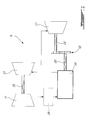
- the system 8 includes a compressor 11 and a turbine 13 which are connected by a shaft 15, and which act as a turbocharger to one or more rotary engines 10.
- the compressor 11 may be a single-stage or multiple-stage centrifugal device and/or an axial device.
- a rotary engine 10, or a plurality of rotary engines, receives compressed air from the compressor 11. The air optionally circulates through an intercooler 16 between the compressor 11 and the rotary engine(s) 10.
- the exhaust gas exiting the rotary engine 10 is supplied to the compressor turbine 13 and also to a power turbine 17, the turbines 13, 17 being shown here in series, i.e. with the exhaust gas flowing first through one of the two turbines where the pressure is reduced, and then through the other turbine, where the pressure is further reduced.
- the turbines 13, 17 are arranged in parallel, i.e. with the exhaust gas being split and supplied to each turbine at same pressure.
- only one turbine is provided.
- the output shaft 19 may be connected via a gear system 21 to a shaft 22 connected to the rotary engine(s) 10.
- the combined output on the shafts 19, 22 may be used to provide propulsive power to a vehicle application into which the system 8 is integrated. This power may be delivered through a gearbox (not shown) that conditions the output speed of the shafts 19, 22 to the desired speed on the application.
- the two shafts 19, 22 may be used independently to drive separate elements, e.g. a propeller, a helicopter rotor, a load compressor or an electric generator depending whether the system is a turboprop, a turboshaft or an APU (Auxiliary Power Unit).
- the system 8 also includes a cooling system, including a circulation system for a coolant to cool the outer body of the rotary engine (e.g. water-ethylene, oil, air), an oil coolant for the internal mechanical parts of the rotary engine, one or more coolant heat exchangers, etc.
- a circulation system for a coolant to cool the outer body of the rotary engine e.g. water-ethylene, oil, air
- an oil coolant for the internal mechanical parts of the rotary engine e.g. water-ethylene, oil, air
- one or more coolant heat exchangers e.g. water-ethylene, oil, air
- the compound engine system 8 may be as described in Lents et al.'s US patent No. 7,753,036 issued July 13, 2010 or as described in Julien et al.'s US patent No. 7,775,044 issued August 17, 2010 .
- the rotary engine 10 forms the core of the compound cycle engine system 8.
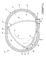
- a Wankel engine an embodiment of the rotary engine 10, known as a Wankel engine, is schematically shown.
- the rotary engine 10 comprises an outer body 12 having axially-spaced end walls 14 with a peripheral wall 18 extending therebetween to form a rotor cavity 20.
- the inner surface of the peripheral wall 18 of the cavity 20 has a profile defining two lobes, which is preferably an epitrochoid.
- An inner body or rotor 24 is received within the cavity 20.
- the rotor 24 has axially spaced end faces 26 adjacent to the outer body end walls 14, and a peripheral face 28 extending therebetween.
- the peripheral face 28 defines three circumferentially-spaced apex portions 30, and a generally triangular profile with outwardly arched sides.
- the apex portions 30 are in sealing engagement with the inner surface of peripheral wall 18 to form three rotating working chambers 32 between the inner rotor 24 and outer body 12.
- the geometrical axis of the rotor 24 is offset from and parallel to the axis of the outer body 12.
- Each rotor apex portion 30 has an apex seal 52 extending from one end face 26 to the other and protruding radially from the peripheral face 28. Each apex seal 52 is biased radially outwardly against the peripheral wall 18 through a respective spring. An end seal 54 engages each end of each apex seal 52, and is biased against the respective end wall 14 through a suitable spring.
- Each end face 26 of the rotor 24 has at least one arc-shaped face seal 60 running from each apex portion 30 to each adjacent apex portion 30, adjacent to but inwardly of the rotor periphery throughout its length.
- a spring urges each face seal 60 axially outwardly so that the face seal 60 projects axially away from the adjacent rotor end face 26 into sealing engagement with the adjacent end wall 14 of the cavity.
- Each face seal 60 is in sealing engagement with the end seal 54 adjacent each end thereof.
- the rotor 24 is journaled on an eccentric portion of a shaft and includes a phasing gear co-axial with the rotor axis, which is meshed with a fixed stator phasing gear secured to the outer body co-axially with the shaft.
- the shaft rotates the rotor 24 and the meshed gears guide the rotor 24 to perform orbital revolutions within the stator cavity.
- the rotor 24 performs three rotations for each orbital revolution. Oil seals are provided around the phasing gear to impede leakage flow of lubricating oil radially outwardly thereof between the respective rotor end face 26 and outer body end wall 14.
- each chamber varies in volumes and moves around the stator cavity to undergo the four phases of intake, compression, expansion and exhaust, these phases being similar to the strokes in a reciprocating-type internal combustion engine having a four-stroke cycle.
- the engine includes a primary inlet port 40, shown here as being defined in the end wall 14; in an alternate embodiment, the primary inlet port 40 may be defined through the peripheral wall 18.
- the primary inlet port 40 is in communication with the exhaust of the compressor 11 through an intake duct 34 which is defined as a channel in the end wall 14.
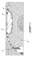
- the primary inlet port 40 delivers air to each of the chambers 32, and a fuel injection port 36 (see Fig. 4 ) is also provided for delivering fuel into each chamber 32 after the air therein has been compressed.
- Fuel such as kerosene (jet fuel) or other suitable fuel
- kerosene jet fuel
- suitable fuel is delivered into the chamber 32 such that the chamber 32 is stratified with a rich fuel-air mixture near the ignition source and a leaner mixture elsewhere, and the fuel-air mixture may be ignited within the housing using any suitable ignition system known in the art (e.g. spark plug, glow plug).
- the engine also includes an exhaust port 44, shown here as being defined through the peripheral wall 18; in an alternate embodiment, the exhaust port 44 may be defined through the end wall 14.
- the exhaust port 44 communicates with the inlet of at least one of the turbines 13, 17.
- the rotary engine 10 operates under the principle of the Miller or Atkinson cycle, with its compression ratio lower than its expansion ratio.
- the ratio obtained by dividing the volumetric compression ratio by the volumetric expansion ratio may be between 0.3 and 0.8, and more particularly about 0.4-0.5.
- the primary inlet port 40 is located further away (i.e. measured as a function of piston rotation) from the exhaust port 44 when compared to a rotary engine having compression and expansion ratios that are equal or approximately equal to one another.
- the angle of the primary inlet port 40, relative to the angle of the exhaust port 44, can then be determined to achieve a desired peak cycle pressure given the inlet air pressure.
- the position of the primary inlet port 40 may vary between the 7 o'clock position up to the 10 o'clock position. In the embodiment shown, the primary inlet port 40 extends between the 8 o'clock and the 9 o'clock positions.
- the primary inlet port 40 is spaced from the exhaust port 44 so that the rotor 24 prevents communication therebetween in all rotor positions.
- the primary inlet port 40 and exhaust port 44 may be in momentary communication with each other throughout the revolution of the rotor 24.
- the rotary engine 10 may also include a secondary inlet port or purge port 42 also in communication with the exhaust of the compressor 11.
- the purge port 42 is shown here as being defined through the end wall 14 and communicating with the same intake duct 34 as the primary inlet port 40; alternately, the purge port 42 may be defined through the peripheral wall 18, and/or be defined independently of the primary inlet port 40.
- the purge port 42 is located rearwardly of the primary inlet port 40 and forwardly of the exhaust port 44 along the direction R of the rotor revolution and rotation.
- the purge port 42 is located such as to be in communication with the exhaust port 44 through each of the chambers 32 along a respective portion of each revolution, to effectively purge each of the chambers 32.
- the purge port 42 may be omitted, particularly but not exclusively when the inlet port 40 and exhaust port 44 are in momentary communication with each other.
- the peripheral face 28 of the rotor 24 includes a recess 38 defined therein between each pair of adjacent apex portions 30.
- the recess 38 defines part of the volume of the corresponding chamber 32; when the chamber 32 is at its minimum volume, for example at Top Dead Center, the recess 38 defines a significant part of the volume of the chamber 32.
- Typical Wankel engines have relatively low rotor recess volume in order to have a high volumetric expansion ratio for a generally higher power output.
- a low recess volume limits the combustion volume which in turn may limit the amount of fuel burned, the rotational speed and the quality of combustion, especially for Wankel engines used with heavy fuel.
- the volume of each recess 38 corresponds to between 5% and 15% of the displacement volume of the corresponding chamber 32 of the rotor 24, with the displacement volume being defined as the difference between the maximum and minimum volume of one chamber 32.
- each recess 38 is at least 6% and at most 11 % of the displacement volume. In a further particular embodiment, the volume of each recess 38 corresponds to about 8 to 10% of the displacement volume. In further particular embodiments the volume of each recess 38 compounds to about 8% or about 10% of the displacement volume.
- the recess 38 may be defined as a single, dual or multiple pocket(s) in the peripheral face, which together define the recess volume.
- the shape of the recess 38 may be different than that of the particular embodiment shown.
- the increased volume of the recess 38 allows for a reduced volumetric compression ratio, which may improve combustion stability and efficiency.
- a higher combustion volume when the rotor 24 comes near Top Dead Center may allow the rotary engine 10 to burn more fuel as more air is available, and as such turn the rotary engine faster and increase the power density.
- the increased ratio of volume to wall surface may also reduce heat losses which tend to quench the flame.
- the increased combustion chamber volume may also allow flexibility in injection spray design.
- the increased volume of the recess 38 correspondingly lowers the expansion ratio and as such would tend to lower the power output of the rotary engine when used alone.
- the lower expansion ratio of the rotary engine 10 is compensated by the expansion within the turbines 13, 17.
- the expansion ratio of the turbines 13, 17 is selected such that the turbine section provides a power output corresponding to from 20% to 35% of the total power output of the compound engine system 8. In a particular embodiment, this may be achieved by having an expansion ratio in the turbine section which is similar to the boost compression pressure ratio, i.e. the compression pressure ratio of the compressor 11.
- the increased power output of the turbine section may provide increased power for a given air mass flow, which may result in a smaller, lighter and more efficient engine at a given power.
- the low volumetric compression ratio of the rotary engine 10 may help heavy fuel (e.g. diesel, kerosene (jet fuel), equivalent biofuel) to remain at a pressure low enough to prevent self-ignition which may help ensure that the cycles runs with direct injection with a source of ignition, may save structural weight, and may reduce internal leakages.
- heavy fuel e.g. diesel, kerosene (jet fuel), equivalent biofuel
- the rotary engine 10 with the increased volume recess may assist in permitting for the large volume and improved combustion in non-intercooled systems such as described in US 7,775,044 , it may also be employed in other suitable systems, such as shown in US 7,753,036 with or without intercooling, assuming suitable expansion ratios are selected. With intercooled systems, use of the larger recess volume may indeed facilitate stable combustion and hence improve such intercooled systems.
Landscapes
- Engineering & Computer Science (AREA)
- Mechanical Engineering (AREA)
- General Engineering & Computer Science (AREA)
- Chemical & Material Sciences (AREA)
- Combustion & Propulsion (AREA)
- Physics & Mathematics (AREA)
- Geometry (AREA)
- Supercharger (AREA)
Applications Claiming Priority (2)
| Application Number | Priority Date | Filing Date | Title |
|---|---|---|---|
| US201161512570P | 2011-07-28 | 2011-07-28 | |
| US13/272,738 US9027345B2 (en) | 2011-07-28 | 2011-10-13 | Compound engine system with rotary engine |
Publications (2)
| Publication Number | Publication Date |
|---|---|
| EP2551447A2 true EP2551447A2 (de) | 2013-01-30 |
| EP2551447A3 EP2551447A3 (de) | 2017-03-08 |
Family
ID=46603605
Family Applications (1)
| Application Number | Title | Priority Date | Filing Date |
|---|---|---|---|
| EP12177792.4A Withdrawn EP2551447A3 (de) | 2011-07-28 | 2012-07-25 | Zusammengesetztes Motorsystem mit Drehmotor |
Country Status (4)
| Country | Link |
|---|---|
| US (4) | US9027345B2 (de) |
| EP (1) | EP2551447A3 (de) |
| CN (1) | CN102900510B (de) |
| CA (1) | CA2782744C (de) |
Cited By (1)
| Publication number | Priority date | Publication date | Assignee | Title |
|---|---|---|---|---|
| EP3361046A1 (de) * | 2017-02-09 | 2018-08-15 | Pratt & Whitney Canada Corp. | Rotierender verbrennungsmotor mit ungleichen volumenverhältnissen |
Families Citing this family (30)
| Publication number | Priority date | Publication date | Assignee | Title |
|---|---|---|---|---|
| US9027345B2 (en) | 2011-07-28 | 2015-05-12 | Pratt & Whitney Canada Corp. | Compound engine system with rotary engine |
| DE102012101032A1 (de) * | 2012-02-08 | 2013-08-08 | Eads Deutschland Gmbh | Kreiskolbenmotor und Verfahren zum Herstellen eines Kreiskolbenmotors |
| GB201313824D0 (en) * | 2013-08-01 | 2013-09-18 | Orbital Power Ltd | A Rotary Engine |
| US9947423B2 (en) | 2013-08-23 | 2018-04-17 | Global Energy Research Associates, LLC | Nanofuel internal engine |
| US11557404B2 (en) | 2013-08-23 | 2023-01-17 | Global Energy Research Associates, LLC | Method of using nanofuel in a nanofuel internal engine |
| US9881706B2 (en) | 2013-08-23 | 2018-01-30 | Global Energy Research Associates, LLC | Nuclear powered rotary internal engine apparatus |
| US11450442B2 (en) | 2013-08-23 | 2022-09-20 | Global Energy Research Associates, LLC | Internal-external hybrid microreactor in a compact configuration |
| CA2933113C (en) * | 2015-06-16 | 2023-09-26 | Pratt & Whitney Canada Corp. | Compound cycle engine |
| US9759128B2 (en) * | 2015-06-16 | 2017-09-12 | Pratt & Whitney Canada Corp. | Compound engine assembly with exhaust pipe nozzle |
| CA2933112C (en) * | 2015-06-16 | 2023-09-26 | Pratt & Whitney Canada Corp. | Compound cycle engine |
| US10696417B2 (en) | 2015-06-25 | 2020-06-30 | Pratt & Whitney Canada Corp. | Auxiliary power unit with excess air recovery |
| US10710738B2 (en) | 2015-06-25 | 2020-07-14 | Pratt & Whitney Canada Corp. | Auxiliary power unit with intercooler |
| US9771165B2 (en) | 2015-06-25 | 2017-09-26 | Pratt & Whitney Canada Corp. | Compound engine assembly with direct drive of generator |
| US10590842B2 (en) * | 2015-06-25 | 2020-03-17 | Pratt & Whitney Canada Corp. | Compound engine assembly with bleed air |
| US10240522B2 (en) | 2015-08-07 | 2019-03-26 | Pratt & Whitney Canada Corp. | Auxiliary power unit with combined cooling of generator |
| US10240521B2 (en) | 2015-08-07 | 2019-03-26 | Pratt & Whitney Canada Corp. | Auxiliary power unit with variable speed ratio |
| US10253726B2 (en) | 2015-08-07 | 2019-04-09 | Pratt & Whitney Canada Corp. | Engine assembly with combined engine and cooling exhaust |
| US10267191B2 (en) | 2015-08-07 | 2019-04-23 | Pratt & Whitney Canada Corp. | Turboprop engine assembly with combined engine and cooling exhaust |
| US10253687B2 (en) | 2015-08-07 | 2019-04-09 | Pratt & Whitney Canada Corp. | Auxiliary power unit with electrically driven compressor |
| US10641239B2 (en) | 2016-05-09 | 2020-05-05 | Sunnyco Inc. | Pneumatic engine and related methods |
| US10465518B2 (en) | 2016-05-09 | 2019-11-05 | Sunnyco Inc. | Pneumatic engine and related methods |
| US10082029B2 (en) | 2016-07-08 | 2018-09-25 | Pratt & Whitney Canada Corp. | Internal combustion engine with rotor having offset peripheral surface |
| CN106121810B (zh) * | 2016-09-27 | 2018-10-30 | 上海洲跃生物科技有限公司 | 一种变压缩比的汪克尔发动机 |
| US10527012B2 (en) * | 2017-06-29 | 2020-01-07 | Pratt & Whitney Canada Corp. | Engine assembly with engine and cooler compartments |
| US11273927B2 (en) | 2018-04-04 | 2022-03-15 | Honeywell International Inc. | Micro-auxiliary power units |
| CN108730028A (zh) * | 2018-07-18 | 2018-11-02 | 杜三平 | 一种转子往复式发动机 |
| US10907531B1 (en) * | 2018-07-24 | 2021-02-02 | Rotary Research Group LLC | Heavy fuel rotary engine with compression ignition |
| US11174916B2 (en) | 2019-03-21 | 2021-11-16 | Pratt & Whitney Canada Corp. | Aircraft engine reduction gearbox |
| US11365706B2 (en) * | 2020-11-04 | 2022-06-21 | William Todd Hodges | Turbine engine system utilizing an augmented combustion module |
| US11268453B1 (en) | 2021-03-17 | 2022-03-08 | Pratt & Whitney Canada Corp. | Lubrication system for aircraft engine reduction gearbox |
Citations (2)
| Publication number | Priority date | Publication date | Assignee | Title |
|---|---|---|---|---|
| US7753036B2 (en) | 2007-07-02 | 2010-07-13 | United Technologies Corporation | Compound cycle rotary engine |
| US7775044B2 (en) | 2003-02-24 | 2010-08-17 | Pratt & Whitney Canada Corp. | Low volumetric compression ratio integrated turbo-compound rotary engine |
Family Cites Families (61)
| Publication number | Priority date | Publication date | Assignee | Title |
|---|---|---|---|---|
| US3134337A (en) | 1960-06-29 | 1964-05-26 | Nsu Motorenwerke Ag | Gearing for rotary mechanisms |
| US3171590A (en) | 1960-12-16 | 1965-03-02 | Curtiss Wright Corp | Oil seal construction for rotary combustion engines |
| US3102492A (en) | 1961-05-10 | 1963-09-03 | Curtiss Wright Corp | Compensated rotary mechanism construction |
| DE1751680B1 (de) | 1961-07-13 | 1970-09-10 | Yanmar Diesel Engine Co | Luftverdichtende, selbstzündende Kreiskolben-Brennkraftmaschine in Trochoidenbauart |
| US3196847A (en) | 1961-07-31 | 1965-07-27 | Curtiss Wright Corp | Fuel pump for rotary combustion engines |
| DE1401994A1 (de) * | 1962-07-25 | 1968-11-21 | Daimler Benz Ag | Rotationskolben-Brennkraftmaschine in Trochoidenbauart |
| DE1296872B (de) | 1962-08-25 | 1969-06-04 | Krupp Gmbh | Kreiskolben-Brennkraftmaschine |
| US3246636A (en) | 1965-04-15 | 1966-04-19 | Curtiss Wright Corp | Rotary combustion engine and method of operating same |
| DE1300338B (de) | 1965-10-13 | 1969-07-31 | Daimler Benz Ag | Kolben fuer Rotationskolben-Brennkraftmaschine |
| US3405695A (en) | 1966-12-12 | 1968-10-15 | Curtiss Wright Corp | Rotary combustion engine and rotor therefor |
| GB1234932A (en) * | 1967-06-07 | 1971-06-09 | Svenska Rotor Maskiner Ab | Improvements in or relating to rotary internal combustion engines of positive displacement type |
| GB1269042A (en) * | 1968-03-29 | 1972-03-29 | Rolls Royce | Improvements in or relating to rotary piston internal combustion engines |
| DE6921974U (de) | 1968-06-06 | 1972-10-05 | Toyo Kogyo Company Ltd | Drehkolben-brennkraftmaschine. |
| US3606602A (en) | 1968-11-15 | 1971-09-20 | Yanmar Diesel Engine Co | Combustion chamber of rotary pistion engine |
| US3696796A (en) | 1971-02-26 | 1972-10-10 | Curtiss Wright Corp | Fuel combustion in a rotary piston internal combustion engine |
| US3698364A (en) | 1971-02-26 | 1972-10-17 | Curtiss Wright Corp | Fuel combustion system for rotary piston internal combustion engines |
| US3699929A (en) | 1971-05-19 | 1972-10-24 | Gen Motors Corp | Rotary combustion engine |
| US3847517A (en) | 1972-05-15 | 1974-11-12 | Curtiss Wright Corp | Rotary piston for a rotary internal combustion engine |
| US3793996A (en) | 1972-07-18 | 1974-02-26 | Curtiss Wright Corp | Rotary combustion engine with improved firing system |
| US3795227A (en) | 1972-10-24 | 1974-03-05 | Curtiss Wright Corp | Rotary combustion engine with improved firing system |
| US3858557A (en) * | 1973-06-04 | 1975-01-07 | Curtiss Wright Corp | Two-stage rotary engine of trochoidal type |
| US3830599A (en) | 1973-06-25 | 1974-08-20 | Outboard Marine Corp | Rotor and gear assembly for rotary mechanisms |
| US3855972A (en) | 1973-09-28 | 1974-12-24 | Curtiss Wright Corp | Rotary combustion engine with improved firing system |
| GB1435728A (en) * | 1973-10-05 | 1976-05-12 | Rolls Royce Motors Ltd | Combustion chamber arrangement for rotary compression-ignition ic engines |
| US3923012A (en) | 1973-12-12 | 1975-12-02 | Curtiss Wright Corp | Stratified charge rotary engine with high and low pressure fuel supply |
| US3976035A (en) | 1974-09-26 | 1976-08-24 | Texaco Inc. | Rotary engine and method of operation |
| DE2510149C3 (de) * | 1975-03-08 | 1982-01-21 | Audi Nsu Auto Union Ag, 7107 Neckarsulm | Gehäuse einer Kreiskolbenmaschine in Trochoidenbauart |
| US3994266A (en) | 1975-09-09 | 1976-11-30 | Curtiss-Wright Corporation | Rotary diesel engine |
| US4059370A (en) | 1976-06-25 | 1977-11-22 | Caterpillar Tractor Co. | Rotary engine having low thermal conductivity rotor |
| US4066044A (en) | 1976-09-09 | 1978-01-03 | Curtiss-Wright Corporation | Rotary engine with tongue and groove inserts in rotor faces |
| DE2715302C3 (de) | 1977-04-05 | 1980-06-04 | Gert G. Ing.(Grad.) 6200 Wiesbaden Niggemeyer | Kreiskolben-Brennkraftmaschine |
| WO1987004491A1 (en) * | 1986-01-16 | 1987-07-30 | John Anthony Jenes Rees | Turbocompounded two-stroke piston engines |
| US4715338A (en) | 1986-12-30 | 1987-12-29 | Pasquan Raymond F | Rotary engine |
| CN1051072A (zh) | 1990-12-06 | 1991-05-01 | 申卫民 | 转子发动机 |
| US5168846A (en) | 1991-06-14 | 1992-12-08 | Paul Marius A | Rotary engine with variable displacement |
| GB2301632B (en) * | 1995-03-18 | 1998-06-24 | Rolls Royce Plc | Aircraft compound cycle propulsion engine |
| CN2249826Y (zh) * | 1995-11-11 | 1997-03-19 | 刘利 | 一种发动机 |
| US6951211B2 (en) * | 1996-07-17 | 2005-10-04 | Bryant Clyde C | Cold air super-charged internal combustion engine, working cycle and method |
| CN1228506A (zh) * | 1998-03-06 | 1999-09-15 | 李建坤 | 高效提前自压式旋转发动机 |
| DE102004008312A1 (de) | 2004-02-20 | 2005-11-17 | Wankel Super Tec Gmbh | Kreiskolbenbrennkraftmaschine, ausgelegt für Dieselkraftstoff |
| WO2006007562A2 (en) * | 2004-07-01 | 2006-01-19 | Cudd Pressure Control, Inc. | Heave compensated snubbing system and method |
| US7188602B1 (en) | 2004-07-14 | 2007-03-13 | Clr, Llc | Concentric internal combustion rotary engine |
| CN100338336C (zh) * | 2005-04-05 | 2007-09-19 | 雷激 | 球形旋转发动机 |
| US8141360B1 (en) * | 2005-10-18 | 2012-03-27 | Florida Turbine Technologies, Inc. | Hybrid gas turbine and internal combustion engine |
| DE102006020642B4 (de) * | 2006-05-04 | 2019-05-23 | Daimler Ag | Verfahren zum Betrieb einer Brennkraftmaschine und Brennkraftmaschine für ein solches Verfahren |
| US20080141972A1 (en) | 2006-12-15 | 2008-06-19 | United Technologies Corporation | Rotors having flow-modifying members for use in rotary engines |
| US8109252B2 (en) | 2007-04-27 | 2012-02-07 | Power Source Technologies, Inc. | Rotary engine combustion chamber |
| WO2010047960A2 (en) | 2008-10-21 | 2010-04-29 | Pratt & Whitney Rocketdyne, Inc. | Rotary engine with scarped pocket rotor |
| CN201611338U (zh) | 2009-11-05 | 2010-10-20 | 广州岭南电缆有限公司 | 交联电缆绝缘层检测装置 |
| US20120227397A1 (en) | 2011-03-10 | 2012-09-13 | Willi Martin L | Gaseous fuel-powered engine system having turbo-compounding |
| ES2606170T3 (es) | 2011-03-10 | 2017-03-23 | Uav Engines Ltd | Rotor de motor rotativo |
| US9038594B2 (en) * | 2011-07-28 | 2015-05-26 | Pratt & Whitney Canada Corp. | Rotary internal combustion engine with pilot subchamber |
| US9027345B2 (en) * | 2011-07-28 | 2015-05-12 | Pratt & Whitney Canada Corp. | Compound engine system with rotary engine |
| US20130239568A1 (en) | 2012-03-16 | 2013-09-19 | Calnetix Technologies, Llc | Turbo Assist |
| US10018110B2 (en) | 2012-04-04 | 2018-07-10 | Fahim Mahmood | Double bar single wheel rotary combustion engine and the components thereof |
| US9353680B2 (en) * | 2013-03-04 | 2016-05-31 | Pratt & Whitney Canada Corp. | Rotary internal combustion engine with pilot subchamber |
| US9869240B2 (en) | 2015-02-20 | 2018-01-16 | Pratt & Whitney Canada Corp. | Compound engine assembly with cantilevered compressor and turbine |
| US10240522B2 (en) * | 2015-08-07 | 2019-03-26 | Pratt & Whitney Canada Corp. | Auxiliary power unit with combined cooling of generator |
| US10082029B2 (en) | 2016-07-08 | 2018-09-25 | Pratt & Whitney Canada Corp. | Internal combustion engine with rotor having offset peripheral surface |
| CN206111338U (zh) | 2016-09-27 | 2017-04-19 | 上海洲跃生物科技有限公司 | 一种变压缩比的汪克尔发动机 |
| CN206267974U (zh) | 2016-12-06 | 2017-06-20 | 江苏大学 | 一种可实现转子发动机不同压缩比的执行机构 |
-
2011
- 2011-10-13 US US13/272,738 patent/US9027345B2/en active Active
-
2012
- 2012-07-06 CA CA2782744A patent/CA2782744C/en active Active
- 2012-07-25 EP EP12177792.4A patent/EP2551447A3/de not_active Withdrawn
- 2012-07-27 CN CN201210262765.3A patent/CN102900510B/zh active Active
-
2015
- 2015-05-01 US US14/701,809 patent/US9759126B2/en active Active
-
2017
- 2017-08-09 US US15/672,698 patent/US10544733B2/en active Active
-
2019
- 2019-12-19 US US16/720,064 patent/US11187146B2/en active Active
Patent Citations (2)
| Publication number | Priority date | Publication date | Assignee | Title |
|---|---|---|---|---|
| US7775044B2 (en) | 2003-02-24 | 2010-08-17 | Pratt & Whitney Canada Corp. | Low volumetric compression ratio integrated turbo-compound rotary engine |
| US7753036B2 (en) | 2007-07-02 | 2010-07-13 | United Technologies Corporation | Compound cycle rotary engine |
Cited By (4)
| Publication number | Priority date | Publication date | Assignee | Title |
|---|---|---|---|---|
| EP3361046A1 (de) * | 2017-02-09 | 2018-08-15 | Pratt & Whitney Canada Corp. | Rotierender verbrennungsmotor mit ungleichen volumenverhältnissen |
| US10526961B2 (en) | 2017-02-09 | 2020-01-07 | Pratt & Whitney Canada Corp. | Rotary internal combustion engine with unequal volumetric ratios |
| EP3892818A1 (de) * | 2017-02-09 | 2021-10-13 | Pratt & Whitney Canada Corp. | Rotierender verbrennungsmotor mit ungleichen volumenverhältnissen |
| US11261781B2 (en) | 2017-02-09 | 2022-03-01 | Pratt & Whitney Canada Corp. | Rotary internal combustion engine with unequal volumetric ratios |
Also Published As
| Publication number | Publication date |
|---|---|
| US11187146B2 (en) | 2021-11-30 |
| US20130028772A1 (en) | 2013-01-31 |
| US20170335762A1 (en) | 2017-11-23 |
| US20200123971A1 (en) | 2020-04-23 |
| US20150233286A1 (en) | 2015-08-20 |
| CA2782744C (en) | 2019-06-18 |
| US9759126B2 (en) | 2017-09-12 |
| CA2782744A1 (en) | 2013-01-28 |
| US10544733B2 (en) | 2020-01-28 |
| CN102900510B (zh) | 2016-12-21 |
| CN102900510A (zh) | 2013-01-30 |
| US9027345B2 (en) | 2015-05-12 |
| EP2551447A3 (de) | 2017-03-08 |
Similar Documents
| Publication | Publication Date | Title |
|---|---|---|
| US11187146B2 (en) | Compound engine system with rotary engine | |
| US10920662B2 (en) | Compound cycle engine | |
| US10968824B2 (en) | Compound cycle engine | |
| US9856789B2 (en) | Compound cycle engine | |
| US10557407B2 (en) | Rotary internal combustion engine with pilot subchamber | |
| CN107923310B (zh) | 复合循环发动机 | |
| US10393014B2 (en) | Engine assembly with exhaust pipe nozzle | |
| CA2998236A1 (en) | Engine assembly with intercooler | |
| WO2016201568A1 (en) | Compound cycle engine | |
| EP3628839B1 (de) | Motoranordnung mit mehreren drehmotorstapeln |
Legal Events
| Date | Code | Title | Description |
|---|---|---|---|
| PUAI | Public reference made under article 153(3) epc to a published international application that has entered the european phase |
Free format text: ORIGINAL CODE: 0009012 |
|
| AK | Designated contracting states |
Kind code of ref document: A2 Designated state(s): AL AT BE BG CH CY CZ DE DK EE ES FI FR GB GR HR HU IE IS IT LI LT LU LV MC MK MT NL NO PL PT RO RS SE SI SK SM TR |
|
| AX | Request for extension of the european patent |
Extension state: BA ME |
|
| PUAL | Search report despatched |
Free format text: ORIGINAL CODE: 0009013 |
|
| AK | Designated contracting states |
Kind code of ref document: A3 Designated state(s): AL AT BE BG CH CY CZ DE DK EE ES FI FR GB GR HR HU IE IS IT LI LT LU LV MC MK MT NL NO PL PT RO RS SE SI SK SM TR |
|
| AX | Request for extension of the european patent |
Extension state: BA ME |
|
| RIC1 | Information provided on ipc code assigned before grant |
Ipc: F01C 21/18 20060101ALI20170127BHEP Ipc: F01C 20/06 20060101ALI20170127BHEP Ipc: F01C 20/10 20060101ALI20170127BHEP Ipc: F01C 11/00 20060101ALI20170127BHEP Ipc: F01C 21/06 20060101ALI20170127BHEP Ipc: F04C 29/00 20060101ALI20170127BHEP Ipc: F01C 21/10 20060101ALI20170127BHEP Ipc: F01C 20/24 20060101ALI20170127BHEP Ipc: F01C 1/22 20060101AFI20170127BHEP Ipc: F01C 21/08 20060101ALI20170127BHEP |
|
| STAA | Information on the status of an ep patent application or granted ep patent |
Free format text: STATUS: REQUEST FOR EXAMINATION WAS MADE |
|
| 17P | Request for examination filed |
Effective date: 20170907 |
|
| RBV | Designated contracting states (corrected) |
Designated state(s): AL AT BE BG CH CY CZ DE DK EE ES FI FR GB GR HR HU IE IS IT LI LT LU LV MC MK MT NL NO PL PT RO RS SE SI SK SM TR |
|
| STAA | Information on the status of an ep patent application or granted ep patent |
Free format text: STATUS: EXAMINATION IS IN PROGRESS |
|
| 17Q | First examination report despatched |
Effective date: 20200124 |
|
| STAA | Information on the status of an ep patent application or granted ep patent |
Free format text: STATUS: THE APPLICATION HAS BEEN WITHDRAWN |
|
| 18W | Application withdrawn |
Effective date: 20200728 |