EP2551071A1 - Robot hand and robot device - Google Patents
Robot hand and robot device Download PDFInfo
- Publication number
- EP2551071A1 EP2551071A1 EP11759451A EP11759451A EP2551071A1 EP 2551071 A1 EP2551071 A1 EP 2551071A1 EP 11759451 A EP11759451 A EP 11759451A EP 11759451 A EP11759451 A EP 11759451A EP 2551071 A1 EP2551071 A1 EP 2551071A1
- Authority
- EP
- European Patent Office
- Prior art keywords
- link
- joint
- drive
- robot hand
- shaft
- Prior art date
- Legal status (The legal status is an assumption and is not a legal conclusion. Google has not performed a legal analysis and makes no representation as to the accuracy of the status listed.)
- Withdrawn
Links
Images










Classifications
-
- B—PERFORMING OPERATIONS; TRANSPORTING
- B25—HAND TOOLS; PORTABLE POWER-DRIVEN TOOLS; MANIPULATORS
- B25J—MANIPULATORS; CHAMBERS PROVIDED WITH MANIPULATION DEVICES
- B25J15/00—Gripping heads and other end effectors
- B25J15/0009—Gripping heads and other end effectors comprising multi-articulated fingers, e.g. resembling a human hand
Definitions
- Disclosed embodiments relate to a robot hand provided with multi-joint fingers for grasping an object and to a robot device.
- Patent Document 1 discloses such a configuration that in a multi-fingered and multi-joint robot hand, shape memory metal is inserted into adjacent movable fingers, and pulling drive of an inter-finger connecting portion of the shape memory metal is performed by a movable pulley.
- Patent Document 2 discloses such a configuration that in a robot hand in which a first link, a second link, and a third link are coupled to each other, provided is a polymer actuator that extends and contracts to drive the first link by applying a voltage in a state of being coupled between the first link and the second link.
- Patent Document 3 discloses such a configuration that a plurality of links provided at a forefinger and a digitus finger is rotated inward/outward using a worm gear, a worm wheel, and a motor.
- An object of the present invention is to provide a robot hand and a robot device that can easily achieve flexible grasping following a shape of an object to be grasped with respect thereto.
- a robot hand of underactuated mechanism comprises a plurality of actuators, a plurality of joints where the number of the joints is more than the number of the actuators, a palm portion, at least two finger portions each including a plurality of links having bases coupled to the palm portion and coupled being capable of flexion, and a shape-fitting mechanism which is provided in at least one of the finger portion, and which enables to grasp an object to be grasped in an enclosing manner with the finger portions by performing at least one of providing torsional displacement to the links and adjusting drive torque required for driving the joints.
- the embodiment has such a configuration that fingers can grasp an object to be grasped in an enclosing manner by the fingers by a shape-fitting mechanism in which torsional displacement is provided to a link.
- a robot device 1 has a robot body 2 and a personal computer 3 (hereinafter abbreviated as a PC3) that controls operation of the robot body 2.
- a PC3 corresponds to one example of a controller described in the claims.
- the controller may be provided on a side of the robot body 2, for example, it is installed near each joint of the robot body 2, at a palm portion 11 of a robot hand 8, etc.
- the robot body 2 of an illustrated example is a two-joint arm type robot, and is provided with: a first joint actuator 4 fixed to a floor portion; a first arm 5 whose positional posture is controlled by the first joint actuator 4; a second joint actuator 6 fixed at a tip of the first arm 5; a second arm 7 whose positional posture is controlled by the second joint actuator 6; and the robot hand 8 according to the embodiment fixed at a tip of the second arm 7.
- the robot body 2 can bring the robot hand 8 close to an object to be grasped 9 by causing the respective joint actuators 4 and 6 to control positional postures of the corresponding arms 5 and 7, respectively.
- the robot hand 8 then grasps the object to be grasped 9, further controls the positional postures of the respective arms 5 and 7, and thereby can move the object to be grasped 9.
- an actuator not shown in particular
- a robot of further multi-joint robot hand (for example, seven-joint one) may be employed, not limited to two-joint robot hand.
- the PC3 generates/transmits a control command respectively corresponding to the respective actuators 4 and 6 provided at the robot body 2, thereby performs cooperative control of the respective actuators 4 and 6, performs grasp control of the robot hand 8, and controls the whole robot body 2 so as to operate smoothly.
- the robot hand 8 of the illustrated example has the palm portion 11, and three finger portions 12 having bases coupled to the palm portion 11, and arranged extending from the palm portion 11.
- each finger portion 12 three links 16, 17, and 18 are coupled in series through two of a second joint 14 and a third joint 15 that are respectively configured with a hinge, and the link 16 on the base side is coupled to the palm portion 11 through one first joint 13.
- axes of rotation of the respective joints 13, 14, and 15 in the one finger portion 12 are in an arrangement relation parallel to one another, and each finger portion 12 can perform flexion and extension operation like oscillation on one flat surface.
- a twist joint portion 19 is provided in at least one link (the link 16 on the side directly coupled to the palm portion 11 in this example) in at least one (a finger portion 12A located at an upper right in Fig. 2 in this example) of the above-described three finger portions 12.
- Fig. 3 illustrations of a wall portion etc. that constitute a skin of the palm portion 11 having a hollow structure, and the respective links 16, 17, and 18 are appropriately omitted.
- the first link 16 is coupled being capable of flexion to an edge portion of the palm portion 11 through a first joint shaft 21.
- the second link 17 is coupled being capable of flexion to a free end of the first link 16 through a second joint shaft 22, and the third link 18 is coupled being capable of flexion to a free end of the second link 17 through a third joint shaft 23.
- axes of rotation of the three joint shafts 16, 17, and 18 are in an arrangement relation parallel to one another.
- a first joint drive motor 24 is installed in the palm portion 11, and a first joint drive gear 26 fixed to an output shaft of the first joint drive motor 24 meshes with a first joint driven gear 27 fixed to the above-described first joint shaft 21. While supported rotatably with respect to the palm portion 11, the first joint shaft 21 is fixedly combined with the above-described first link 16. As a result, it is possible to actively flex the first link 16 with respect to the palm portion 11 by rotational drive of the first joint drive motor 24. It is to be noted that the first joint drive motor 24 corresponds to one example of an actuator and a first actuator described in each claim.
- a second joint drive motor 25 is installed at the first link 16, and a second joint drive gear 30 is fixed to an output shaft of the second joint drive motor 25.
- the second joint shaft 22 is supported rotatably with respect to the first link 16, and is also supported rotatably with respect to the above-described second link 17 by a bearing 28A.
- the second joint drive gear 30 meshes with a second joint driven gear 31 fixed to the second joint shaft 22.
- the second joint drive motor 25 corresponds to one example of the actuator and a second actuator described in each claim.
- a third joint drive pulley 32 is integrally combined with the above-described second joint driven gear 31. Meanwhile, a third joint driven pulley 33 is fixed to the third joint shaft 23, and a belt 34 is spanned between the third joint driven pulley 33 and the above-described third joint drive pulley 32. It is to be noted that a wire member may be used. While supported rotatably with respect to the second link 17 by a bearing 28B, the third joint shaft 23 is fixedly combined with the above-described third link 18. As a result, the rotational drive of the second joint drive motor 25 is transmitted through the belt 34, and thereby the third link 18 can be actively flexed with respect to the second link 17.
- both the second link 17 and the third link 18 operate so as to flex toward the same side while the second joint drive motor 25 is rotationally driven.
- the third link 18 is flexed in an underactuated mode of the second link 17. It is to be noted that a flexion angle of the third link 18 is affected also by a pulley diameter ratio of the above-described third joint drive pulley 32 and third joint driven pulley 33.
- first link 16 is separated into two of a first small link 35 and a second small link 36 along an axial line direction thereof.
- a tip portion of the first small link 35 located on a palm portion 11 side is fitted and inserted inside the second small link 36 located on a fingertip side (second link 17 side).
- a fitting portion of the first small link 35 is formed in a cylindrical shape, and a fitting portion of the second small link 36 is formed having a substantially same inner diameter as that of an outer circumference of the cylindrical portion.
- the first small link 35 and the second small link 36 are mutually coupled so as to be capable of relative torsional displacement around an axis of rotation along a longitudinal direction of the whole first link 16, and the twist joint portion 19 is configured with such a fitting portion (refer to an A portion in the above-described Fig. 2 ).
- a small link bearing is provided between an outer circumference of the first small link 35 and an inner circumference of the second small link 36, this small link bearing 37 makes smooth sliding between the first small link 35 and the second small link 36 in a radial direction, and prevents fall-out between the first small link 35 and the second small link 36 in a thrust direction.
- the above-described second joint drive motor 25 is installed inside the second small link 36. It is to be noted that the first small link 35 and the second small link 36 correspond to one example of two small link members described in each claim.
- twist mechanism 38 that assists the relative torsional displacement between the above-described first small link 35 and second small link 36.
- a detailed structure of the twist mechanism 38 will be explained using Fig. 4 .
- the twist mechanism 38 has: a shaft support plate 41; a shaft 42; a guide plate 43; a shaft bearing 44; two guide bars 45; and a torsion spring 46.
- the shaft support plate 41 and the guide plate 43 are formed in a disk shape with a substantially same diameter, respectively, and are arranged in parallel, mutual central axes thereof coinciding with each other.
- the shaft 42 is formed in a hollow cylindrical shape, one end (a lower end in Fig. 3 ) thereof is fixed to a center of the shaft support plate 41, the other end (a top end in Fig. 3 ) thereof penetrates a center of the guide plate 43, and the shaft 42 is rotatably supported through the shaft bearing 44.
- each of the two guide bars 45 is vertically combined with the shaft support plate 41, and the other end (top end in Fig. 3 ) thereof is made to penetrate the corresponding guide groove 47.
- Respective combinations of the guide bars 45 and the guide grooves 47 are in a same arrangement relation, and for example, when the guide bar 45 is located at the end of one guide groove 47 as shown in the drawing, the guide bar 45 is located at the corresponding end also in the other guide groove 47.
- the shaft support plate 41, the shaft 42, and the two guide bars 45 are relatively rotatably coupled with respect to the guide plate 43 by the inner circumferential angle of each guide groove 47.
- the torsion spring 46 is a spring rolled spirally, is coaxially arranged on an outer circumference of the shaft 42, one end (a lower end in Fig. 3 ) of the torsion spring 46 is fixed to the shaft support plate 41, and the other end (a top end in Fig. 3 ) thereof is fixed to the guide plate 43.
- the guide plate 43 is always biased in a same rotational direction (a counter clockwise direction in an example shown in Fig. 4 ) from the shaft support plate 41.
- the shaft 42 corresponds to one example of a shaft member described in each claim
- the shaft bearing 44 corresponds to one example of a bearing member.
- Side wall portions of the guide bars 45 and 45 and the guide grooves 47 and 47 correspond to one example of a guide member, and groove ends of the guide grooves 47 and 47 correspond to one example of a regulating member.
- the torsion spring 46 corresponds to one example of a first spring member and one example of a return force providing member.
- the twist mechanism 38 having such configuration is penetrated and arranged in a state where the fitting portion (i.e., the twist joint portion 19) of the above-described first small link 35 and second small link 36 is made to coincide with the axis of rotation.
- the shaft support plate 41 is fixed inside the first small link 35
- the guide plate 43 is fixed inside the second small link 36.
- the shaft 42 is formed in a state where a through-hole 48 penetrates in an axial direction in the inside thereof, and a cable member 49 of the above-described second joint drive motor 25 is made to pass through the through-hole 48.
- the shaft bearing 44 is provided at the second small link 36 to rotatably support the shaft 42.
- the two guide bars 45 and the two guide grooves 47 guide relative rotation of the first small link 35 and the second small link 36 along with the rotation of the shaft 42, and regulate within predetermined ranges amounts of rotation in relative rotation directions of the first small link 35 and the second small link 36 along with the rotation of the shaft 42.
- the torsion spring 46 along with the rotation of the shaft 42, provides return force that displaces the first small link 35 and the second small link 36 that are displaced in a positive rotation direction (a direction where the guide plate 43 of the second small link 36 is displaced in the counter clockwise direction, and the shaft support plate 41 of the first small link 35 is displaced in a clockwise direction, i.e., the direction moving away from each other, in Fig. 4 ) in a reverse rotation direction opposite to the above.
- a shape-fitting mechanism US having the first small link 35 and the second small link 36, the twist joint portion 19, and the twist mechanism 38 is provided at the finger portion 12A, torsional displacement is provided to the second link 17 and the third link 18, and whereby it becomes possible to grasp the object to be grasped 9 in an enclosing manner by the three finger portions 12.
- an axis line of the third joint shaft 23 between the third link 18 and the second link 17, and an axis line of the second joint shaft 22 between the second link 17 and the first link 16 are parallel to each other, and these joint shafts are respectively driven so as to mutually flexed by the second joint drive motor 25 arranged inside the second small link 36.
- each flexion joint of the first joint shaft 21, the second joint shaft 22, and the third joint shaft 23 that have only a single degree of freedom, respectively has only a degree of freedom enough to oscillate (flex/extend) the respective links 16, 17, and 18 in a same flat surface even though the flexion joints are combined with one another.
- the first link 16 is provided with the twist joint portion 19, and it is possible to perform relative rotation (relative torsional displacement) around an axis of rotation CL of the first small link 35 and the second small link 36 as shown in the figure, thus allowing a degree of freedom of movement of the fingertip to be further increased.
- the twist joint portion 19 is constrained around a Z axis by the torsion spring 46, and is arranged between the first small link 35 and the second small link 36.
- the twist joint portion 19, the first small link 35, and the second small link 36 correspond to the first link 16.
- the second joint 14, the second link 17, the third joint 15, and the third link 18 are arranged at the free end of the first link 16, and the first link 16 is driven by the first joint 13.
- An axial center point of the first joint 13 is defined as an original point, a length from the first joint 13 to the twist joint portion 19 is 10, a length from the first joint 13 to the second joint 14 is 11, and a length from the second joint 14 to the third joint 15 is 12.
- Equation (3) a Jacobian matrix of a position and posture is expressed by the following Equation (3).
- Equation (3) is eventually expressed by a form of the following Equation (4) by utilizing a Lagrange method etc.
- the actuator that drives the first joint 13 is the first joint drive motor 24, and this first joint drive motor 24 is provided with a control device (not shown in particular) that outputs a motor current.
- This control device inputs a deviation signal of a first joint command calculated by the PC3 based on the above-described equation of motion and angle information by an encoder (not shown in particular) of the motor 24, outputs the corresponding motor current, and thereby drives the first joint drive motor 24.
- Drive force of the first joint drive motor 24 corresponds to actuator torque ⁇ 1 , and controls flexion operation in the first joint 13. It is to be noted that this actuator torque ⁇ 1 corresponds to one example of first drive force described in each claim.
- actuators that drive the second joint 14 are the second joint drive motor 25, and gears 30 and 31, and an actuator that drives the third joint 15 is the second joint drive motor 25.
- a deviation signal of a second joint command calculated by the PC3 and angle information by an encoder (not shown in particular) of the second joint drive motor 25 is input to a control device (not shown) provided at the second joint drive motor 25, the corresponding motor current is input, and the second joint drive motor 25 is driven.
- Drive force of the second joint drive motor 25 corresponds to actuator torque ⁇ 2 , and controls flexion operation in the second joint 14 and the third joint 15. It is to be noted that this actuator torque ⁇ 2 corresponds to one example of second drive force described in each claim.
- the second joint drive gear 30 fixed to the output shaft of the second joint drive motor 25 drives the second joint driven gear 31 fixed to the second joint shaft 22. That is, the second joint drive motor 25 transmits the actuator torque ⁇ 2 to the second link 17 through the second joint drive gear 30 and the second joint driven gear 31, and flexes the second link 17 centering on the second joint shaft 22.
- the second joint drive gear 30 and the second joint driven gear 31 correspond to one example of a gear mechanism described in each claim, and also correspond to one example of a drive transmission mechanism for a second link.
- the second joint drive gear 30 fixed to the output shaft of the second joint drive motor 25 drives the second joint driven gear 31 fixed to the second joint shaft 22, further drives the third joint drive pulley 32 and the belt 34, and transmits force to the third joint driven pulley 33 fixed to the third joint shaft 23. That is, the second joint drive motor 25 also transmits the actuator torque ⁇ 2 to the third link 18 through the second joint drive gear 30, the second joint driven gear 31, the third joint drive pulley 32, the belt 34, and the third joint driven pulley 33, and flexes the third link 18 centering on the third joint shaft 23.
- the third joint drive pulley 32, the third joint driven pulley 33, and the belt 34 correspond to one example of a pulley mechanism described in each claim, and that these and the second joint drive gear 30 and the second joint driven gear 31 correspond to one example of a drive transmission mechanism for a third link described in each claim.
- the embodiment has such a structure that at least one link 16 of any one of finger portion 12A of a plurality of finger portions 12 and 12A that are provided at the robot hand 8 is separated into the two small links 35 and 36, and that these two small links 35 and 36 are coupled to each other. Relative torsional displacement of these two small links 35 and 36 can be mutually performed around the axis line CL of the finger portion 12A.
- the finger portion 12A provided with the separated link 16 can operate not only in a grasp direction approaching the object to be grasped 9 and in a release direction moving away from the object 9 as mentioned above, but can perform movement so that an angle toward the object 9 is changed to change posture opposed to the object 9.
- At least one finger portion 12A provided with the shape-fitting mechanism US that allows for such a movement, and thereby the robot hand 8 in the embodiment can perform flexible grasping following a shape of the object 9 with respect thereto than in a structure of a prior art.
- the relative rotations of the two small links 35 and 36 of the twist mechanism 38 along with the rotation of the shaft 42 are guided by the guide bar 45 and the guide groove 47 of the guide plate 43.
- the small link 35 of one side and the small link 36 of the other side are relatively displaced more smoothly, and thereby smoother movement of the finger portion 12A provided with the two small links 35 and 36 can be achieved.
- the amounts of rotation in the relative rotation directions of the small links 35 and 36 along with the rotation of the shaft 42 are regulated within the predetermined ranges by the above-described guide groove 47 of the twist mechanism 38.
- the relative displacement of the small link 35 of the one side and the small link 36 of the other side is suppressed within a certain range, and the robot hand 8 can be controlled not to take improper posture and not to perform unnatural operation.
- smoother movement is achieved, and durability and reliability can also be improved.
- the torsion spring 46 of the twist mechanism 38 provides the return force that displaces to the reverse rotation direction the two small links 35 and 36 that are displaced in the positive rotation direction along with the rotation of the shaft 42.
- passive stable grasping operation conforming to the shape of the object 9 can be achieved.
- a contact area with the object 9 increases between the third link 18 of the fingertip and the first link 16 of the base, and also thereby stable grasp can be performed.
- the two small links 35 and 36 can be automatically made to return to an original state before the relative displacement even though compulsory drive force is not provided in a return direction. As a result of these, movement close to that of human fingers, and having little feeling of strangeness can be reliably achieved.
- the first link 16 of the palm portion 11 side is configured with the two small links 35 and 36 capable of relative torsional displacement, and large posture change from a base side of the finger portion 12A can be performed.
- the first link 16 is oscillated (flexed and extended) by the actuator torque ⁇ 1 from the first joint drive motor 24 arranged at the palm portion 11
- the second link 17 and the third link 18 are oscillated (flexed and extended) by the actuator torque ⁇ 2 of the two-joint drive motor 25 arranged at the first link.
- the first link 16, and the second link 17 and the third link 18 can be mutually independently oscillated (flexed and extended).
- the second joint drive motor 25 is arranged at the second small link 36 of the second link 17 side, and while transmitted to the second link 17 by the second joint drive gear 30 and the second joint driven gear 31, the actuator torque ⁇ 2 from the second joint drive motor 25 is transmitted also to the third link 18 by the third joint drive pulley 32, the belt 34, and the third joint driven pulley 33.
- the above-described third joint drive gear 30, third joint driven gear 31, third joint drive pulley 32, belt 34, and third joint driven pulley 33 can transmit the actuator torque ⁇ 2 from the second joint drive motor 25 to the third link 18.
- the third link 18 can be smoothly driven by the underactuated mode of the second link 17, and natural flexion operation like human that works with flexion operation of the second link 17 can be achieved.
- the actuators for driving the second link 17 and the third link 18 are commonized as one second joint drive motor 25 as described above, and the first joint drive motor 24 for driving the first link 16 is arranged at the palm portion 11, whereby the actuator arranged at the finger portion 12A is only one second joint drive motor 25. As a result of this, weight reduction of the whole finger portion 12A can also be achieved.
- the through-hole 48 for making penetrate the cable member 49 to the second joint drive motor 25 is provided at the shaft 42, and thereby the cable member 49 of the second joint drive motor 25 that is arranged at the second small link 36 of the second link 17 side can be smoothly disposed at the palm portion 11 without being exposed to the outside of the robot hand 8.
- a power amplifier of the actuator can be arranged at the palm portion 11, and also thereby weight reduction of the finger portion 12A can be achieved.
- the present invention is not regulated to this.
- the plurality of (or all) finger portions 12 may have the configuration, or the links 17 and 18 other than the first link 16 may have it.
- the return force of displacing the second small link 36 and the first small link 35 in the twist mechanism 38 in the reverse rotation direction with respect to the relative torsional displacement therebetween is obtained by the torsion spring 46, but the present invention is not regulated to this.
- a configuration may be employed in which the above-described return force is obtained by the tension spring spanned between the guide plate 43 and the guide bar 45.
- a twist mechanism 38A of the modified example is not provided with the torsion spring 46 in the above-described embodiment, and instead, it is provided with two helical springs 51. These two helical springs 51 are spanned between the corresponding ends on the fingertip side (front side in the drawing) of the guide bar 45 and ends of the guide groove 47 that are initial positions of the helical springs 51, and always provide biasing force to pull the guide bar 45 to the respective ends. It is to be noted that the helical spring 51 corresponds to one example of a spring member described in each claim and one example of the return force providing member.
- passive stable grasping operation and return to the original state after grasp release can be performed utilizing the biasing force due to elasticity of the helical spring 51, thus enabling to obtain an effect similar to that of the above-described embodiment.
- a twist mechanism 38B of the modified example is not provided with the torsion spring 46 in the above-described embodiment, and instead, a permanent magnet 52 is provided on respective surfaces opposed to each other of the shaft support plate 41 and the guide plate 43.
- magnetic poles (a north pole and a south pole) of each permanent magnet 52 is arranged so that the pair of permanent magnets 52 opposed to each other mutually exerts attraction force in a state where the shaft support plate 41 and the guide plate 43 are located at initial relative rotation positions.
- the opposing permanent magnets 52 has a combination of the north pole and the south pole, or of the south pole and the north pole, always provide force of trying to return the shaft support plate 41 and the guide plate 43 to the initial positions.
- a shaft 42B and a guide bar 45B are formed comparatively short, and the shaft support plate 41 and the guide plate 43 are arranged so as to be sufficiently close to each other.
- a non-magnetic material with a low density, for example, aluminum for each member of the shaft support plate 41, the shaft 42B, the guide plate 43, and the guide bar 45B that constitute the twist mechanism 38B.
- the permanent magnet 52 corresponds to one example of the return force providing member described in each claim.
- passive stable grasping operation and return to the original state after grasp release can be performed utilizing the attraction force with which the pair of permanent magnets 52 and 52 is pulled to each other, thus enabling to obtain an effect similar to that of the above-described embodiment.
- a non-contact scheme utilizing the magnetic force depression and deterioration of durability due to fatigue and aging can be reliably prevented from occurring, and part replacement also becomes unnecessary.
- a twist mechanism 38C of the modified example has: the shaft support plate 41; the shaft 42; a rubber member storage body 53; a coupling member 54, two pressing members 55, and two rubber members 56.
- the shaft support plate 41 and the shaft 42 are formed and fixed equal to those of the above-described embodiment, respectively.
- the whole rubber member storage body 53 is formed in a columnar shape with a substantially same diameter as that of the shaft support plate 41, and the shaft 42 penetrates an axial center of the rubber member storage body 53 to be supported rotatably.
- two arc-shaped deep grooves 57 that respectively make a same inner circumferential angle with the axial center of the rubber member storage body 53 are formed in the rubber member storage body 53, and a rubber member 56 having a substantially same arc shape as the deep groove 57 and formed long in the axial direction is stored inside each deep groove 57. Gap is provided among ends of the rubber member 56 and the deep groove 57 corresponding to one another in a combination thereof, and the pressing member 55 with a flat plate shape is inserted in the gap, respectively.
- An end on the fingertip side (the front side in Fig. 9A , and the right side in Fig.
- each pressing member 55 projects from an end of the rubber member storage body 53, respectively, and it is fixed to a free end of the shaft 42 through the coupling member 54 with a flat plate shape. Additionally, when the twist mechanism 38C of the modified example is provided inside the first link 16, the shaft support plate 41 is fixed to the first small link 35 (together with the shaft 42 and the pressing member 55), and the rubber member storage body 53 is fixed to the second small link 36. It is to be noted that the rubber member 56 corresponds to one example of the return force providing member described in each claim.
- each pressed rubber member 56 is elastically deformed so as to extend along a direction of the axis of rotation as shown with a dashed line in Fig. 9B , and that this amount of elastic deformation is decided by a Poisson's ratio of a material of the rubber member 56.
- a robot hand can grasp an object in an enclosing manner in any posture by providing auxiliary torque by a spring member.
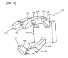
- the robot hand 108 has a palm portion 111 and three finger portions 112 having bases coupled to the palm portion 111.
- three links 116, 117, and 118 are coupled in series through two second joint 114 and third joint 115 that are configured with hinges, respectively, further, the link 116 of the base side is coupled to the first joint 113, and each finger portion 112 can perform flexion and extension operation like oscillation on one flat surface.
- the three finger portions 112 are flexed so as to be close to one another, and thereby the robot hand 108 can grasp the object 9 with the three links 116, 117, and 118 and finger pads of the three finger portions 112.
- the robot hand 108 of the embodiment is provided with an underactuated mechanism that interlockingly drives adjacent two joints of the above-described three finger portions 112 by one electric motor.
- Fig. 11 shows a skin of a part of the palm portion 111 with the hollow structure and the each links 116, 117, and 118.
- Fig. 11 shows a state where a wall portion, etc. are appropriately omitted.
- a base of the first link 116 is fixed to a first joint shaft 1131 provided at an edge portion of the palm portion 111, and the first joint shaft 1131 and an output shaft of a first motor 119 (actuator) are coupled by a coupling 121A.
- the first joint shaft 1131 is rotatably supported by a bearing 126A provided at the palm portion 111. According to such a configuration, the whole finger portion 112 is oscillated (flexed and extended) at the first joint 113 with respect to the palm portion 111 by torque generated by the first motor 119.
- a second motor 120 (actuator) is installed on the fingertip side of the first link 116.
- An output shaft of the second motor 120 and a second joint shaft 1141 are coupled by a coupling 121B.
- the second joint shaft 1141 is rotatably supported by a bearing 126E provided at a base of the second link 117, and a bearing 126B provided at the first link 116.
- a drive pulley 122 is fixed to the second joint shaft 1141, and rotation angles of the drive pulley 122 and the second joint shaft 1141 coincide with each other.
- the third link 118 is coupled to a fingertip side of the second link 117.
- a base of the third link 118 is fixed to a third joint shaft 1151.
- the third joint shaft 1151 is rotatably supported by a bearing 126D provided at the fingertip side of the second link 117.
- a driven pulley 123 is provided at the third joint shaft 1151.
- a belt 124 is spanned between the drive pulley 122 and the driven pulley 123, and torque of the drive pulley 122 is transmitted to the driven pulley 123 through the belt 124.
- An idle pulley 125 provided at an intermediate portion of the second link 117 is also in contact with the belt 124. This idle pulley 125 plays a role to adjust tension of the belt 124.
- the drive pulley 122, the driven pulley 123, and the belt 124 correspond to one example of a torque transmission mechanism described in the claims.
- a stopper 128 that regulates posture of the second link 117 with respect to the first link 116.
- This stopper 128 is configured with a pin 128A provided at the first link 116, and a guide groove 128B provided at the second link 117.
- a stopper 129 that regulates posture of the third link 118 with respect to the second link 117.
- This stopper 129 is configured with a pin 129A provided at the second link 117, and a guide groove 129B provided at the third link 118.
- the pin 129A is installed upright inside the second link 117.
- the guide groove 129B is provided at the third link 118 so as to be parallel to an outer circumference centering on the third joint shaft 1151, and is configured so as to be able to restrict an operation range of the inserted pin 129A.
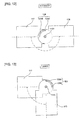
- the stopper 129 regulates posture of the third link 118 with respect to the second link 117 so that an axial line of the second link 117 and an axial line of the third link 118 do not extend to not less than 180 degrees centering on the third joint shaft 1151 as shown in Fig. 12 , and so that the axial line of the second link 117 and the axial line of the third link 118 are not flexed at an acute angle (for example, not more than 90 degrees) centering on the third joint shaft 1151 as shown in Fig. 13 .
- the stopper 128 also has the configuration similar to that of the above-described stopper 129.
- a coiled torsion spring 127 is provided around the second joint shaft 1141. Although illustration is omitted, one end of the torsion spring 127 is fixed to the first link 116, and the other end thereof is fixed to the second link 117. As a result, the torsion spring 127 provides auxiliary torque to the second joint 114 so that drive torque required for driving the second joint 114 is smaller than drive torque required for driving the third joint 115 in grasping operation being performed, and so that the drive torque required for driving the second joint 114 is larger than the drive torque required for driving the third joint 115 in grasp release operation being performed.
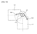
- FIG. 14 One example of a configuration of the torsion spring 127 will be explained ( Fig. 14 ). It is to be noted that illustration of the stopper 128 is omitted in Fig. 14 .
- the torsion spring 127 is inserted around the second joint shaft 1141. One of free ends of the torsion spring 127 is fixed to a pin 135A provided inside the first link 116, and another free end of the torsion spring 127 is fixed to a pin 135B provided inside the second link 117.
- the pins 135A and 135B are arranged so as to be in a state where the second link 117 is flexed, for example, at 90 degrees with respect to the first link 116 in a natural state where the second motor 120 is not turned on.
- the torsion spring 127 corresponds to one example of a drive torque adjusting member described in the claims, and also corresponds to one example of the second spring member.
- the motor 119 drives the first joint shaft 1131 and performs posture control of the first link 116
- the motor 120 drives the second joint shaft 1141 and the third joint shaft 1151. Since the motor 120, the second joint shaft 1141, and the third joint shaft 1151 are underactuated mechanisms, the motor 120 cannot arbitrarily perform angle control of the third joint shaft 1151.
- the underactuated mechanism is a mechanism with smaller actuator degree of freedom than a degree of freedom of an object to be controlled. A point where an input degree of freedom is smaller than this output degree of freedom is advantageous to following grasp (grasp so as to follow a shape of the object).
- two joint shafts are provided for one motor.
- the motor 119 performs posture control of the first link 116 so that the first link 116 first approaches the object to be grasped 9.
- the motor 120 drives the second link 117 and the third link so that the second link 117 and the third link 118 get contact with the object to be grasped 9.
- the underactuated mechanism (the motor 120 drives the second link 117 and the third link 118) of the embodiment will be explained in detail.
- each link (the second link 117 and the third link 118) starts to move is important in order to stably grasp the object to be grasped 9 with the hand, and an order during flexion operation is carried out with the third link 118 after the second link 117, and an order during extension operation is carried out with the second link 117 after the third link 118.
- the torsion spring 127 and the stopper 129 are provided in order to reliably perform the operation. It is to be noted that the second link 117 may start extension in the middle of extension of the third link 118.
- the torsion spring 127 works with little torque at the time of flexion operation so that the third link 118 starts to move after the second link 117, and works so that the second link 117 starts to move after the third link 118 unless large torque is provided at the time of extension operation.
- desired flexion and extension operation can be achieved even in any posture.
- the stopper 129 is a part required for extension operation, and if a torsion spring is added and there is no stopper 129, only the third link 118 works and the second link cannot be moved. That is, desired extension operation cannot be realized without the stopper 129.
- the stopper 128 restricts the second joint shaft 1141 so that an angle between the second link 117 and the first link 116 does not become not less than a certain set angle (for example, 180 degrees) centering on the second joint shaft 1141.
- the second link 117 is in flexion posture (posture in a grasp direction) when a brake is not applied in a case where power supply of the second motor 120 is not on.
- an initial state of the second link 117 corresponds to the flexion posture under the influence of the torsion spring 127.
- the second link 117 and the third link 118 is preferably in extension posture. Consequently, a voltage command is issued from the PC3 to the second motor 120 so as to rotate counterclockwise seen from the right side in Fig. 11 (in a paper-based front direction of a fingertip side in Fig.
- extension operation of the third link 118 is stopped by the stopper 129 and further, extension operation of the second link 117 is stopped by the stopper 128.
- the state where the first link 116, the second link 117, and the third link 118 are extended in series is set as initial posture, and the state is stored in a memory of the PC3 as an initial angle 0 degree of the second motor 120.
- an angle before power-on and an angular difference (a rotation angle) at the time of being constrained by the stopper 128 are also stored in the PC3.
- An angular difference 0 is utilized to return the robot hand to the initial posture after the power-on, and the initial posture can be kept easily by issuing the angular difference as a target angle command.
- the shape-fitting mechanism US having the drive pulley 122, the driven pulley 123, the belt 124, and the torsion spring 127 as the torque transmission mechanism is provided at the finger portion 112, and in performing grasping operation, flexion drive of the second joint 114 is performed prior to the third joint 115, and in performing grasp release operation, extension of the third joint 115 is driven prior to the second joint 114.
- the torsion spring 127 enough to hold self-weights of the second link 117 and the third link 118 is selected, and thereby flexible grasping following the shape of the object to be grasped 9 can be performed by the finger portion 112 even in any posture.
- the stopper 129 that regulates the posture of the third link 118 with respect to the second link 117 is provided at the finger portion 112.
- the third link 118 first starts extension, operation of the third link 118 is stopped at a predetermined angle and subsequently, the second link 117 can be extended. Namely, extension operation of the second link 117 can be reliably started after the extension of the third link 118.
- the second motor 120 is arranged outside the second link 116 so that the output shaft of the second motor 120 and the second joint shaft 1141 coincide with each other, it is more preferable for the second motor 120 to be arranged so as not to interfere with the other finger portions 112. Accordingly, the second motor 120 may be arranged inside the first link 116.
- the modified example will be explained with reference to Fig. 15 . However, only components related to arrangement of the second motor 120 will be explained.
- the second motor 120 of the modified example is fixed to the inside of the first link 116.
- An output shaft 131 of the second motor 120 is supported by a bearing 132A arranged at the skin of the first link 116, and a gear 130A is coupled to this output shaft 131.
- a gear 130C is coupled to the second joint shaft 1141 in parallel with the drive pulley 122.
- a gear 130B (idle gear) is arranged inside the first link 116 so as to mesh with these gears 130A and 130C.
- An idle gear shaft 133 that is coupled to the gear 130B is supported by a bearing 132B arranged at the skin of the first link 116.
- the other configurations are similar to those of the above-described second embodiment.
- the torsion spring 127 can be installed both ends of the second joint shaft 1141 as shown in Fig. 15 because of unnecessity of providing the coupling 121B, auxiliary torque can be increased.
- the gear 130B is provided n order to make the same a rotational direction of the second motor 120 and rotational directions of the second joint 114 and the third joint 115, the gear 130B may be eliminated f it is not necessary to coincide the rotational directions thereof. In this case, further weight reduction can be achieved.
- the modified example is an example where a worm gear is used instead of a spur gear in the configuration of the above-described modified example (2-1).
- the modified example will be explained with reference to Fig. 16 .
- the second motor 120 is arranged inside the first link 116 so that an axial direction thereof may conform to a link longitudinal direction.
- the output shaft 131 of the second motor 120 is coupled to a worm 134, and this worm 134 is supported by bearings 136A and 136B installed inside the first link 116.
- the gear 130A is arranged so as to mesh with the worm 134
- the gear 130B is arranged inside the first link 116 so as to mesh with the gears 130A and 130C.
- the gear 130C is coupled to the second joint shaft 1141 in parallel with the drive pulley 122 similarly to the one explained in the above-described modified example (2-1).
- torsion spring 127 provides auxiliary torque to the second joint 114 in the above-described second embodiment
- a tension spring may be used instead of the torsion spring 127.
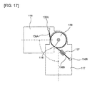
- the modified example will be explained with reference to Fig. 17 .
- a first wire 138A is fixed to the pin 135A provided inside the first link 116, and the other end of the first wire 138A is coupled to an end of a coiled tension spring 137.
- Another end of the tension spring 137 is coupled to a second wire 138B, and the second wire 138B is fixed to the pin 135B provided inside the second link 117.
- a part of the first wires 138A is in a state of being in contact with a pulley 139 rotatably supported by the second joint shaft 1141. This pulley 139 is installed in parallel with the drive pulley 122.
- the pins 135A and 135B are arranged so as to be in a state where the second link 117 is flexed at 90 degrees with respect to the first link 116. Also according to the modified example, an effect similar to that of the above-described second embodiment is obtained. It is to be noted that the tension spring 137 corresponds to one example of the drive torque adjusting member described in the claims, and also corresponds to one example of the second spring member.
- each finger portion 112 is configured with the three links 116, 117, 118, respectively has been explained as one example in the above-described second embodiment
- the shape-fitting mechanism US may be provided for a finger portion configured with two links.
- the modified example will be explained with reference to Figs. 18 to 21 .
- the robot hand 108 has such a configuration that the finger portion 212 corresponding to a thumb couples two links 216 and 217 in series through the second joint 214, and that the link 216 on the palm side is coupled to the palm portion 111 through the first joint 213.
- Configurations of the other two finger portions 112 are the same as those of the above-described second embodiment.
- the finger portion 212 can perform flexion operation on one flat surface oblique to oscillating surfaces of the other finger portions 112. These three finger portions 112, 212 flex so as to be close to one another, and thereby the robot hand 108 can grasp the object to be grasped 9.
- an output shaft of the first motor 219 (actuator) and a first joint shaft 2131 are coupled to each other by a coupling 221.
- the first joint shaft 2131 is rotatably supported by a bearing 226A provided at the palm portion 111 and a bearing 226C provided at the first link 216. According to such a configuration, the whole finger portion 212 is flexed at the first joint 213 with respect to the palm portion 111 by torque generated by the first motor 219.
- a principle that the first joint shaft 2131 and a second joint shaft 2141 are respectively driven by the first motor 219 is similar to a principle in Fig. 11 that the second motor 219 drives the second joint shaft 1141 and the third joint shaft 1151, respectively.
- the second link 217 is coupled to a fingertip side of the first link 216.
- a base of the second link 217 is fixed to the second joint shaft 2141.
- This second joint shaft 2141 is rotatably supported by a bearing 226B provided on the fingertip side of the first link 216.
- a driven pulley 223 is provided at the second joint shaft 2141.
- a belt 224 is spanned between a drive pulley 222 and the driven pulley 223, and torque of the drive pulley 222 is transmitted to the driven pulley 223 through the belt 224. It is to be noted that the drive pulley 222, the driven pulley 223, and the belt 224 correspond to one example of the torque transmission mechanism described in the claims.
- a coiled torsion spring 227 is provided around both ends of the first joint shaft 2131.
- One end of each torsion spring 227 is fixed to the palm portion 111, and the other end thereof is fixed to the first link 216. Even though the hand 108 takes any posture, the torsion spring 227 acts so that the second joint shaft 2141 is driven subsequent to the first joint shaft 2131 at the time of flexion operation, and so that the first joint shaft 2131 is driven subsequent to the second joint shaft 2141 at the time of extension operation.
- the torsion spring 227 provides auxiliary torque to the first joint 213.
- a stopper 228 that regulates posture of the first link 216 with respect to the palm portion 111 is provided at the first joint 213.
- This stopper 228 regulates the posture so that the palm portion 111 and the first link 216 do not extend to not less than 180 degrees centering on the first joint shaft 2131. It is to be noted that at the time of flexion operation of the first link 216, the first link 216 gets contact with an end surface 1111 of the palm portion 111, and thereby the posture is regulated so that the palm portion 111 and the first link 216 do not flex at an acute angle (for example, not more than 90 degrees).
- a stopper 229 that regulates posture of the second link 217 with respect to the first link 216.
- This stopper 229 regulates posture so that the first link 216 and the second link 217 do not extend to not less than 180 degrees centering on the second joint shaft 2141, and they do not flex at an acute angle (for example, not more than 90 degrees).
- the stopper 229 acts to reliably drive the first joint shaft 2131 subsequent to the second joint shaft 2141 at the time of extension operation. Configurations of these stoppers 228 and 229 are the same as those of the above-mentioned stopper 128 and 129.
- the shape-fitting mechanism US having the drive pulley 222, the driven pulley 223, the belt 224, and the torsion spring 227 as the torque transmission mechanism is provided at the finger portion 212, and drive torque required for driving the first joint 213 is adjusted, whereby it becomes possible to grasp the object to be grasped in an enclosing manner by the finger portions 212.
- the finger portion 212 corresponding to the thumb of the robot hand 108 has such a configuration that the two links 216 and 217 are coupled to each other in an example shown in Fig. 20 , unlike the example shown in Fig. 19 , the first link 216 on the palm side is flexed on a flat surface substantially perpendicular to oscillating flat surfaces of the other two finger portions 112 through the first joint 213, and the second link 217 can perform flexion operation through the second joint 214 on a flat surface parallel to the oscillating flat surface of the finger portion 112.
- a bevel gear 230 is provided at the first joint shaft 2131 coupled to an output shaft of the first motor 219 by the coupling 221.
- This bevel gear 230 similarly meshes with the bevel gear-shaped drive pulley 222.
- the belt 224 is spanned between the drive pulley 222 and the driven pulley 223 provided at the second joint shaft 2141, and torque of the drive pulley 222 is transmitted to the driven pulley 223 through the belt 224. It is to be noted that a point where the coiled torsion spring 227 is provided around the first joint shaft 2131, and a point where the stoppers 228 and 229 are provided at the first joint shaft 213 and the second joint shaft 214 are similar to the configuration shown in Fig. 19 .
- Figs. 21A and 21B are views of the robot hand 108 seen from a wrist direction (lower side in Fig. 20 ), and that Fig. 21C is a view thereof seen from a side surface direction (right side in Fig. 20 ).
- the output shaft of the first motor 219 rotates clockwise seen from the lower side in Fig. 20 (clockwise in Fig. 21 )
- the first joint shaft 2131 and the bevel gear 230 similarly rotate clockwise through the coupling 221.
- the first link 216 rotates together with the first joint shaft 2131, and the first link 216 is flexed from a state shown in Fig.
- inward rotation operation that brings the finger portions close to one another and outward rotation operation that keeps the finger portions away from one another
- a configuration in which inward rotation/outward rotation operation can be performed may be employed in order that flexible grasping following a shape of an object to be grasped can be performed.
- the modified example will be explained with reference to Figs. 22 to 29 .
- a robot hand 300 has a palm portion 311 and three finger portions 312, 313, and 314 having bases coupled to the palm portion 311.
- the finger portion 312 is configured with four links 301, 302, 303, and 304, and the adjacent links are coupled to one another.
- the base link 301 is coupled to a gear 305, and the gear 305 meshes with a gear 306.
- the base link 301 oscillates on a flat surface parallel to the palm portion 311 by a drive motor 307 of the gear 306.
- a gear 309 coupled to a base link 315 of the finger portion 313 meshes with the gear 306 through a gear 308.
- a base link 315 oscillates on the flat surface parallel to the palm portion 311 by the drive motor 307.
- the gear 308 is provided so that rotational directions of the gear 305 and the gear 309 are opposite to each other (for example, so that the gear 309 rotates counterclockwise in the gear 305 rotating clockwise).
- the finger portion 314 oscillates on the flat surface parallel to the palm portion 311 by a drive motor 310 coupled to a base link 316.
- the base link 301 is arranged between the palm portion 311 and a back portion of the hand 317, and the above-described drive motor 307 and 310 are installed at the back portion of the hand 317.
- the palm portion 311 and the back portion of the hand 317 are fixed to each other with a plurality of bolts 318 with a spacer 350 being sandwiched therebetween.
- An output shaft of the drive motor 307 is coupled to a shaft 320, and this shaft 320 is supported by a bearing 319 provided inside the palm portion 311, and a bearing 321 provided inside the back portion of the hand 317.
- a shaft 322 coupled to the base link 301 is also supported by the bearing 319 and the bearing 321.
- the gear 306 coupled to the shaft 320 and the gear 305 coupled to the shaft 322 mesh with each other.
- the drive motors 307 and 310 are arranged on the side of the back portion of the hand 317, and thereby motor replacement can be performed easily.
- a motor 330 (actuator) is arranged inside the base link 301, and an output shaft of the motor 330 is coupled to a bevel gear 323.
- the bevel gear 323 meshes with a bevel gear 324 arranged coaxially with a first joint pulley 325.
- a belt 326 is spanned between the pulleys 325 and 327, and similarly, in order to transmit drive force of the second joint pulley 327 to a third joint pulley 329, a belt 328 is spanned between the pulleys 327 and 329.
- Rotational torque of the motor 330 works as force of flexing/extending each link.
- a torsion spring (not shown) is provided at a first joint 331 and a second joint 332 of the finger portion 312.
- the torsion spring provides auxiliary torque to the first joint 331 and the second joint 332 so that drive torque required for driving the first joint 331 is smaller than drive torque required for driving the second joint 332 and a third joint 333, and so that the drive torque required for driving the second joint 332 is smaller than the drive torque required for driving the third joint 333, in grasping operation being performed, and also so that the drive torque required for driving the first joint 331 is larger than the drive torque required for driving the second joint 332 and the third joint 333, and so that the drive torque required for driving the second joint 332 is larger than the drive torque required for driving the third joint 333, in grasp release operation being performed.
- the stoppers similar to those of the above-mentioned second embodiment are provided between the links 301 and 302, the links 302 and 303, and the links 303 and 304.
- the shape-fitting mechanism US having the pulleys 325, 327, and 329, the belts 326 and 328, and the torsion spring as the torque transmission mechanism is provided, and the torsion spring adjusts drive torque required for driving the joints 331, 332, and 333.
- the torsion spring adjusts drive torque required for driving the joints 331, 332, and 333.
- FIGs. 25 and 26 a state is shown where the comparatively large object to be grasped 9 has been grasped by the hand robot 300.
- An image of the object to be grasped 9 in this case is, for example, an empty can.
- each finger portion does not perform inward rotation/outward rotation operation, but first, the first link gets contact with a part of the palm, the second link gets contact with the can after the operation is completed, further the third link gets contact with another point of the can, and grasping operation is completed.
- the robot hand 300 grasps the empty can following a shape thereof.
- a state is shown where the comparatively small object to be grasped 9 has been grasped by the hand robot 300.
- the object to be grasped 9 is an object having a rectangular parallelepiped shape, and is grasped by the two finger portions 312 and 314.
- the first links of the finger portions 312 and 314 get contact with a part of the palm
- the second links do not get contact with the object to be grasped 9 after completion of the operation
- the third links get contact with the object to be grasped 9, and grasping operation is completed.
- the object to be grasped 9 is grasped by the finger portions 312 and 314 has been shown as one example in the above, it may be grasped by the finger portions 313 and 314, or it may be grasped by the finger portions 312 and 313 after performing outward rotation of the finger portions 312 and 313 so that an angle therebetween is made to be 180 degrees.
- the robot hand 300 can perform flexible grasping following the shape of the object to be grasped 9 with respect thereto.
- a weight of the finger portion can be reduced more than in the above-mentioned second embodiment, and cost can be reduced.
- a worm 331 is coupled in the base link 301.
- a worm wheel 333 is arranged so as to mesh with the worm 331.
- a gear 334 is arranged in the middle of the inside of the base link 301 in order to transmit rotation of the worm wheel 331 to the first joint pulley 325.
- the gear 334 meshes with a gear 335 arranged to be coaxial with the first joint pulley 325.
- a bearing (not shown) is provided in the gear 305, and the gear 305 and the base link 301 are coupled to each other so that torque of the motor 330 and torque of the gear 305 do not interfere with each other.
- the other configurations in which the first link, the second link, and the third link are driven are similar to those of the above-mentioned Fig. 24 .
- Such a configuration may be employed that a reduction device is also combined with the above-mentioned first motor and second motor. In that case, output torque becomes large.
- a wire made by winding a thin wire (made of metal or nylon) around a wire core may be used for a belt, and even if both ends of the wire are joined with metal via a drive pulley, a driven pulley, and an idle pulley to make a circle, the operation shown in the above can be achieved, and in this case, if a resin material is used for a drive pulley, a driven pulley, and an idle pulley, a drive transmission system becomes lightweight.
- adjustment of drive torque required for driving joints is performed by constraining drive of a joint shaft on a fingertip side using a joint constraining mechanism included in the shape-fitting mechanism, and thereby an object can be grasped in an enclosing manner by fingers.
- a whole finger portion 400 included in the robot hand in accordance with the embodiment will be explained using Figs. 30 and 31 .
- a planetary gear mechanism 401 included inside the finger portion 400 will be explained using Fig. 30 .
- Fig. 30 In Fig.
- the planetary gear mechanism 401 has: a shaft 4101 that inputs output torque from a coupling 409 to a sun gear 4102; a planetary gear 4103 that inputs output of the sun gear 4102 to a carrier 4104; a carrier cup 4105 provided at the carrier 4104; the planetary gear 4103 that inputs the output of the sun gear 4102 to a ring gear 4106 in rotation of the carrier cup 4105 being stopped; a ring gear cup 4107 that has the ring gear 4106 thereinside; a bearing 4109 that rotatably supports the ring gear cup 4107; and a case 4108 that protects the planetary gear mechanism 401.
- cogs are provided at top surfaces of the carrier cup 4105 and the carrier cup 4107. It is to be noted that the planetary gear mechanism 401 corresponds to one example of the torque transmission mechanism described in the claims.
- Fig. 31 in the finger portion 400, the carrier cup 4105 of the planetary gear mechanism 401 oscillates a second link 417 through the gear 403 in a paper-based depth direction and a paper-based front direction in Fig. 31 .
- the second link 417 does not get warped in the paper-based front direction.
- Base sides of the gear 403 and the second link 417 are coupled to a second joint shaft 407 of a second joint 425. Namely, the second link 417 rotates centering on the second joint shaft 425 by rotation of the gear 403, and the finger portion 400 is flexed at the second joint 425.
- the ring gear cup 4107 of the planetary gear mechanism 401 rotates a third joint shaft 420 of a third joint 424 through the gear 405, bevel gears 406 and 415, the shaft 416, and bevel gears 418 and 419, and oscillates a third link 421 in the paper-based depth direction and the paper-based front direction.
- the third link 421 does not get warped in the paper-based front direction.
- Relative angle displacement of the gear 405 and the bevel gear 406 is constrained to be zero, and these gears 405 and 406 are rotatable to the second joint shaft 425. That is, although omitted on the paper, a bearing is incorporated inside the gear 405 and 406.
- a spring 422 is constrained so that a relative angle of the third link 421 and the second link 417 is zero. Constraint of drive of the third joint shaft 420 by the spring 422 is performed until the second link 417 gets contact with the object to be grasped 9 and rotation of the second joint shaft 407 is stopped, and the ring gear cup 4107 maintains a rest state in the meantime.
- Drive torque of the planetary gear mechanism 401 is differential torque of two pairs of motors 413 (actuators), and is input to the sun gear 4102 of the planetary gear mechanism 401 through bevel gears 411 and 412, the shaft 410, and the coupling 409.
- synthetic torque of two pairs of motors 413 is the torque for oscillating a first link 414 around the first joint shaft 426 in the paper-based depth direction and the paper-based front direction.
- a planetary gear mechanism is a mechanism that fixes any one of a sun gear, a carrier, and a ring gear, and decelerates or accelerates output with respect to input.
- the sun gear 4102 serves as input and the carrier 4104 and the ring gear 4106 serve as output.
- the ring gear 4106 is indirectly constrained by the spring 422 so that the second joint 425 starts to move prior to the third joint 424 in grasping operation being performed.
- the finger portion 400 is provided with the sun gear 4102, the carrier 4104, and the ring gear 4106, and provided is the shape-fitting mechanism US having: the planetary gear mechanism 401 in which the carrier 4104 is indirectly coupled to the second joint shaft 407, and the ring gear 4106 is to the third joint shaft 420; and the spring 422 that constrains rotation of the third joint shaft 420 so that drive torque required for driving the second joint shaft 407 is smaller than drive torque required for driving the third joint shaft 420 (in other words, adjusts so as to increase drive torque of the third joint shaft) in grasping operation being performed, and it becomes possible to grasp the object to be grasped 9 by the finger portion 400 by adjusting drive torque required for driving the third joint 424.
- the spring 422 corresponds to one example of the drive torque adjusting member and the joint constraining mechanism described in the claims.
- angle control of the first link 414 is performed by the synthetic torque
- angle control of the second link 417 and the third link 421 is performed by the differential torque.
- a case is considered where one point of an inner circumference and one point of an outer circumference of a doughnut-shaped object (tape for packing, etc.) by the robot hand with two fingers.
- posture control of the first link is performed so that the two fingers are arranged at the inner circumference and the outer circumference of the doughnut-shaped object.
- posture control of the second and third links is performed, and thereby it becomes possible to grasp one point of the inner circumference and one point of the outer circumference of the doughnut-shaped object. In a manner described above, posture control can be achieved even in underactuation.
- Fig. 32 the planetary gear mechanism 401 is provided with: the sun gear 4102; the planetary gear 4103; the carrier 4104; and the ring gear 4106, and the ring gear 4106 is indirectly constrained by the spring 422 as mentioned above.
- This spring 422 is arranged between the second link 417 and the third link 421.
- Fig. 32A shows a state where input torque to the sun gear 4102 is zero.
- Fig. 32B when clockwise torque is input to the sun gear 4102, the planetary gear 4103 rotates, and simultaneously the carrier 4104 similarly rotates clockwise.
- the shape-fitting mechanism US having the planetary gear mechanism 401 and the spring 422 as the torque transmission mechanism is provided at the finger portion 400, the second joint 425 and the third joint 424 are flexed in that order in grasping operation being performed, and it becomes possible to grasp the object to be grasped in an enclosing manner by the finger portion 400 even in any posture by adjusting drive torque required for driving the third joint 424.
- the robot hand can perform flexible grasping following the shape of the object to be grasped 9 with respect thereto.
- the cogs are provided at the top surfaces of the carrier cup 4105 and the ring gear cup 4107, and torque is transmitted using the cogs in the above-described third embodiment, the invention is not regulated to this, and such a configuration may be employed that torque transmission is performed using a pulley.
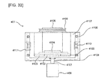
- the modified example will be explained with reference to Fig. 33 .
- the planetary gear mechanism 401 is provided with a pulley 4109 and a pulley 4110 in outer circumferences of the carrier cup 4105 and the ring gear cup 4107, respectively, and is provided with a hole (or gap) 4111 through which belt transmission is performed to a case 4108.
- the other configurations are similar to those of the above-described third embodiment. Also according to the modified example, an effect similar to that of the above-described third embodiment is obtained.
- the third joint 424 is constrained by constraining the relative angle of the third link 421 and the second link 417 using the spring in the above-described third embodiment, the invention is not regulated to this, and the shaft 416 may be constrained.
- the modified example will be explained with reference to Fig. 34 .
- a joint constraining mechanism JC that constrains drive of the third joint shaft 420 is provided inside the second link 417.
- This joint constraining mechanism JC has: a stopper 505; a spring 504 provided on one side of the stopper 505; a support member 506 that is provided on the other side of the stopper 505, and that connects the stopper 505 and a pad 503.
- Fig. 34A represents a state before the second link 417 gets contact with the object to be grasped 9
- Fig. 34B represents a state after the second link 417 got contact with the object to be grasped 9. As shown in Fig.
- the stopper 505 before the second link 417 gets contact with the object to be grasped 9, the stopper 505 is in contact with the shaft 416 due to weight of the spring 504 and the stopper 505.
- the shaft 416 is constrained by the stopper 505, thereby the ring gear cup 4107 is constrained, and a relative angle of the second link 417 and the third link 421 becomes zero.
- the pad 503 gets contact with the object to be grasped 9
- the support member 506 is pushed inside the second link 417
- the spring 504 is shrunk, the stopper 505 detaches from the shaft 416, and constraint of the shaft 416 is lost.
- Fig. 34C is a side portional view of the second link 417, and as shown in this Fig. 34C , the stopper 505 has a configuration that partially covers the shaft 416.
- the joint constraining mechanism JC constrains drive of the joint shaft 420 of the third joint 424 so that drive torque required for driving the second joint 425 is larger than the drive torque required for driving the third joint 424 in grasp release operation being performed. As a result, it is possible to grasp the object to be grasped in an enclosing manner by the finger portion 400.
- a robot hand has the three-joint finger portion 400 configured with the first link 414, the second link 417, and the third link 421, and a palm portion 606.
- the above-mentioned planetary gear mechanism 401 is incorporated inside the first link 414.
- a contact sensor 605 is provided outside the second link 417.
- a sensor that outputs an electrical signal in response to stress (for example, a strain gauge, a pressure sensor, etc.) is used as the contact sensor 605.
- An electrical signal of the contact sensor 605 is input to an amplifier 608 in the inside of the second link 417 through a cable 607, and the amplified signal is applied to shape memory alloy 610 in the inside of the first link 414 through a cable 609.
- the joint constraining mechanism JC in the inside of the first link 414 has: a stopper 611 that constrains the ring gear cup 4107; the coiled shape memory alloy 610 that connects the inside of the first link 414 and the stopper 611; and the cable 609 that applies a current to the shape memory alloy 610 and a spring 613.
- the contact sensor 605 is not in contact with the object to be grasped 9
- a current applied to the shape memory alloy 610 is small, and therefore the stopper 611 constrains the ring gear cup 4107 by tensional force of the spring 613 as shown in Fig. 35B .
- the present invention is not regulated to this, and a wave gear mechanism may be used.
- the modified example will be explained with reference to Figs. 36 and 37 .
- a wave gear mechanism 700 has: a wave generator 701; a flex spline 702; and a circular spline 703.
- a flex spline cup gear 704 is provided at the flex spline 702
- a circular spline cup gear 705 is provided at the circular spline 703.
- a bearing 706 is arranged between the circular spline 703 and a case 707, and the circular spline 703 is rotatably supported.
- the wave gear mechanism 700 serves as a single-input double-output torque transmission mechanism similar to the planetary gear mechanism 401 of the above-described third embodiment.
- the modified example has a configuration in which the planetary gear mechanism 401 of the finger portion 400 shown in Fig. 31 is replaced with the wave gear mechanism 700 by using the wave gear mechanism 700 to drive the second joint 425 and the third joint 424 of the robot hand, and therefore the same operation can be achieved.
- the wave generator 701 serves as input
- the flex spline cup gear 704 and the circular spline cup gear 705 serve as output.
- a flex spline cup 708 and a pulley 709 are provided at the flex spline 702 (not shown in Fig. 37 ), and a pulley 710 is provided in the circular spline 703.
- a belt that is not shown is spanned between these pulleys 709 and 710, and a pulley provided at a finger of the robot hand, and thereby torque is transmitted.
- the other configurations are similar to the above. Also according to the modified example, an effect similar to that of the above-described third embodiment is obtained.
- the belt between the pulleys 709 and 710, and the pulley provided at the finger of the robot hand is lengthened, and thereby it also becomes possible to store the wave gear mechanism 700 described in the modified example in the palm portion, and the finger portion can be made lightweight.
Landscapes
- Engineering & Computer Science (AREA)
- Robotics (AREA)
- Mechanical Engineering (AREA)
- Manipulator (AREA)
Abstract
Description
- Disclosed embodiments relate to a robot hand provided with multi-joint fingers for grasping an object and to a robot device.
- In recent years, development of a robot that can replace human beings in work has been expected. A hand of the robot particularly needs to be able to handle tools etc. used by a human. As prior arts related to such a robot hand, there has been already known arts described in
Patent Documents 1 to 3, for example. - The prior art described in
Patent Document 1 discloses such a configuration that in a multi-fingered and multi-joint robot hand, shape memory metal is inserted into adjacent movable fingers, and pulling drive of an inter-finger connecting portion of the shape memory metal is performed by a movable pulley. - The prior art described in
Patent Document 2 discloses such a configuration that in a robot hand in which a first link, a second link, and a third link are coupled to each other, provided is a polymer actuator that extends and contracts to drive the first link by applying a voltage in a state of being coupled between the first link and the second link. - The prior art described in
Patent Document 3 discloses such a configuration that a plurality of links provided at a forefinger and a digitus finger is rotated inward/outward using a worm gear, a worm wheel, and a motor. -
- Patent Document 1:
JP, A, 2009-83020 Fig. 1 ) - Patent Document 2:
JP, A, 2005-46980 Fig. 1 ) - Patent Document 3:
JP, A, 2008-149448 Fig. 1 ) - However, in the prior arts described in
Patent Documents Patent Document 3 are functions of only making a plurality of fingers operate in opening/closing directions by planarly rotating links, and there has been a limit in performing flexible grasping following the shape of the object to be grasped. In any cases, flexible grasping following the shape of the object has been unable to be achieved easily in the above-described prior arts. - An object of the present invention is to provide a robot hand and a robot device that can easily achieve flexible grasping following a shape of an object to be grasped with respect thereto.
- In order to achieve the above-described object, according to one aspect of the present invention, there is provided a robot hand of underactuated mechanism. The robot hand comprises a plurality of actuators, a plurality of joints where the number of the joints is more than the number of the actuators, a palm portion, at least two finger portions each including a plurality of links having bases coupled to the palm portion and coupled being capable of flexion, and a shape-fitting mechanism which is provided in at least one of the finger portion, and which enables to grasp an object to be grasped in an enclosing manner with the finger portions by performing at least one of providing torsional displacement to the links and adjusting drive torque required for driving the joints.
- According to the present invention, flexible grasping following a shape of an object to be grasped with respect thereto can be easily achieved.
-
-
Fig. 1 is a conceptual explanatory view of a robot device provided with a robot hand in accordance with a first embodiment. -
Fig. 2 is a perspective view representing an external structure of the robot hand in accordance with the first embodiment. -
Fig. 3 is a longitudinal sectional view showing an internal structure of a whole finger portion provided with a twist joint portion. -
Fig. 4 is an external perspective view of a twist mechanism that is provided at the twist joint portion. -
Fig. 5 is a perspective view of a finger portion provided with three flexion joints and one twist joint portion. -
Fig. 6 is a model view of a four-joint finger of the finger portion provided with the twist joint portion. -
Fig. 7 is an elevational view of a guide plate of a twist mechanism in a modified example where return force is obtained by a tension spring. -
Fig. 8 is a main part enlarged longitudinal sectional view of a first link in a modified example where return force is obtained by a permanent magnet. -
Fig. 9A is an elevational view of the twist mechanism in a modified example where return force is obtained by a rubber member. -
Fig. 9B is a sectional side view taken along a cross section IX-IX inFig. 9A . -
Fig. 10 is a perspective view representing an external structure of a robot hand in accordance with a second embodiment. -
Fig. 11 is a longitudinal sectional view showing an internal structure of a whole finger portion provided with an underactuated mechanism. -
Fig. 12 is a schematic view showing one example of a configuration of a stopper in a state where a link is extended. -
Fig. 13 is a schematic view showing one example of the configuration of the stopper in a state where the link is flexed. -
Fig. 14 is a schematic view showing one example of a configuration of a torsion spring. -
Fig. 15 is a longitudinal sectional view of an internal structure of a whole finger portion in a modified example where a second motor is arranged in a link. -
Fig. 16 is a longitudinal sectional view of an internal structure of a whole finger portion in a modified example where the second motor is arranged in the link using a worm gear. -
Fig. 17 is a schematic view representing one example of a modified example using a tension spring. -
Fig. 18 is a perspective view showing an external structure of a robot hand in a modified example where the robot hand has a finger portion configured with two links. -
Fig. 19 is a longitudinal sectional view showing an internal structure of the whole finger portion configured with the two links. -
Fig. 20 is a longitudinal sectional view showing an internal structure of a finger portion configured with two links in an other configuration example. -
Fig. 21 is a view for explaining operation of the finger portion configured with the two links in the other configuration example. -
Fig. 22 is a plan view showing an external structure of a robot hand in a modified example having a configuration capable of inward rotation/outward rotation operation of a finger portion. -
Fig. 23 is a sectional side view showing details of a palm portion of the robot hand in the modified example having the configuration capable of inward rotation/outward rotation operation of the finger portion. -
Fig. 24 is a sectional side view showing an internal schematic structure of the finger portion of the robot hand in the modified example having the configuration capable of inward rotation/outward rotation operation of the finger portion. -
Fig. 25 is a top view showing a state of having grasped a large object to be grasped by a robot hand in the modified example having the configuration capable of inward rotation/outward rotation operation of the finger portion. -
Fig. 26 is a side view showing the state of having grasped the large object to be grasped by the robot hand in the modified example having the configuration capable of inward rotation/outward rotation operation of the finger portion. -
Fig. 27 is a top view showing a state of having grasped a small object to be grasped by the robot hand in the modified example having the configuration capable of inward rotation/outward rotation operation of the finger portion. -
Fig. 28 is a side view showing a state of having grasped the small object to be grasped by the robot hand in the modified example having the configuration capable of inward rotation/outward rotation operation of the finger portion. -
Fig. 29 is a sectional side view showing a configuration in which a motor is arranged at a back portion of a hand in the modified example having the configuration capable of inward rotation/outward rotation operation of the finger portion. -
Fig. 30 is a sectional side view of a planetary gear mechanism provided at a finger portion of a robot hand in accordance with a third embodiment. -
Fig. 31 is a sectional side view of the whole finger portion of the robot hand in accordance with the third embodiment. -
Fig. 32 is an explanatory view for explaining an operating principle of the finger portion in accordance with the third embodiment. -
Fig. 33 is a sectional side view of a planetary gear mechanism of a modified example where torque transmission is performed using a pulley. -
Fig. 34 is a view representing a configuration of a joint constraining mechanism that constrains a joint by constraining a shaft. -
Fig. 35 is a view representing the configuration of the joint constraining mechanism that constrains the joint by constraining the shaft using shape memory alloy. -
Fig. 36A is a horizontal sectional view of a wave gear mechanism in a modified example where the wave gear mechanism is used as a torque transmission mechanism. -
Fig. 36B is a sectional side view of the wave gear mechanism in the modified example where the wave gear mechanism is used for the torque transmission mechanism. -
Fig. 37 is a sectional side view of a wave gear mechanism of a modified example where torque transmission is performed using a pulley. - First, a first embodiment will be explained. The embodiment has such a configuration that fingers can grasp an object to be grasped in an enclosing manner by the fingers by a shape-fitting mechanism in which torsional displacement is provided to a link.
- In
Fig. 1 , arobot device 1 has arobot body 2 and a personal computer 3 (hereinafter abbreviated as a PC3) that controls operation of therobot body 2. It is to be noted that the PC3 corresponds to one example of a controller described in the claims. In addition, the controller may be provided on a side of therobot body 2, for example, it is installed near each joint of therobot body 2, at apalm portion 11 of arobot hand 8, etc. - The
robot body 2 of an illustrated example is a two-joint arm type robot, and is provided with: a firstjoint actuator 4 fixed to a floor portion; afirst arm 5 whose positional posture is controlled by the firstjoint actuator 4; a secondjoint actuator 6 fixed at a tip of thefirst arm 5; asecond arm 7 whose positional posture is controlled by the secondjoint actuator 6; and therobot hand 8 according to the embodiment fixed at a tip of thesecond arm 7. - In the above-described configuration, the
robot body 2 can bring therobot hand 8 close to an object to be grasped 9 by causing the respectivejoint actuators arms robot hand 8 then grasps the object to be grasped 9, further controls the positional postures of therespective arms robot hand 8 is moved only by rotating operation of the twojoint actuators respective arms - The PC3 generates/transmits a control command respectively corresponding to the
respective actuators robot body 2, thereby performs cooperative control of therespective actuators robot hand 8, and controls thewhole robot body 2 so as to operate smoothly. - In
Fig. 2 , therobot hand 8 of the illustrated example has thepalm portion 11, and threefinger portions 12 having bases coupled to thepalm portion 11, and arranged extending from thepalm portion 11. In eachfinger portion 12, threelinks link 16 on the base side is coupled to thepalm portion 11 through one first joint 13. In this example, axes of rotation of therespective joints finger portion 12 are in an arrangement relation parallel to one another, and eachfinger portion 12 can perform flexion and extension operation like oscillation on one flat surface. The threefinger portions 12 flex so as to be close to one another, and thereby therobot hand 8 can grasp the object to be grasped 9 by three-point support. Additionally, as a feature of therobot hand 8 of the embodiment, a twistjoint portion 19 is provided in at least one link (thelink 16 on the side directly coupled to thepalm portion 11 in this example) in at least one (afinger portion 12A located at an upper right inFig. 2 in this example) of the above-described threefinger portions 12. - Next, an internal structure of the
whole finger portion 12A provided with the above-mentioned twistjoint portion 19 will be explained usingFig. 3 . It is to be noted that inFig. 3 , illustrations of a wall portion etc. that constitute a skin of thepalm portion 11 having a hollow structure, and therespective links - In
Fig. 3 , thefirst link 16 is coupled being capable of flexion to an edge portion of thepalm portion 11 through a firstjoint shaft 21. Thesecond link 17 is coupled being capable of flexion to a free end of thefirst link 16 through a secondjoint shaft 22, and thethird link 18 is coupled being capable of flexion to a free end of thesecond link 17 through a thirdjoint shaft 23. In a usual state, axes of rotation of the threejoint shafts - A first
joint drive motor 24 is installed in thepalm portion 11, and a firstjoint drive gear 26 fixed to an output shaft of the firstjoint drive motor 24 meshes with a first joint drivengear 27 fixed to the above-described firstjoint shaft 21. While supported rotatably with respect to thepalm portion 11, the firstjoint shaft 21 is fixedly combined with the above-describedfirst link 16. As a result, it is possible to actively flex thefirst link 16 with respect to thepalm portion 11 by rotational drive of the firstjoint drive motor 24. It is to be noted that the firstjoint drive motor 24 corresponds to one example of an actuator and a first actuator described in each claim. - A second
joint drive motor 25 is installed at thefirst link 16, and a secondjoint drive gear 30 is fixed to an output shaft of the secondjoint drive motor 25. The secondjoint shaft 22 is supported rotatably with respect to thefirst link 16, and is also supported rotatably with respect to the above-describedsecond link 17 by abearing 28A. In addition, the secondjoint drive gear 30 meshes with a second joint drivengear 31 fixed to the secondjoint shaft 22. As a result, it is possible to actively flex thesecond link 17 with respect to thefirst link 16 by rotational drive of the secondjoint drive motor 25. It is to be noted that the secondjoint drive motor 25 corresponds to one example of the actuator and a second actuator described in each claim. - A third
joint drive pulley 32 is integrally combined with the above-described second joint drivengear 31. Meanwhile, a third joint drivenpulley 33 is fixed to the thirdjoint shaft 23, and abelt 34 is spanned between the third joint drivenpulley 33 and the above-described thirdjoint drive pulley 32. It is to be noted that a wire member may be used. While supported rotatably with respect to thesecond link 17 by a bearing 28B, the thirdjoint shaft 23 is fixedly combined with the above-describedthird link 18. As a result, the rotational drive of the secondjoint drive motor 25 is transmitted through thebelt 34, and thereby thethird link 18 can be actively flexed with respect to thesecond link 17. In addition, since thebelt 34 is simply spanned (is not twisted) between the twopulleys second link 17 and thethird link 18 operate so as to flex toward the same side while the secondjoint drive motor 25 is rotationally driven. In other words, thethird link 18 is flexed in an underactuated mode of thesecond link 17. It is to be noted that a flexion angle of thethird link 18 is affected also by a pulley diameter ratio of the above-described thirdjoint drive pulley 32 and third joint drivenpulley 33. - Additionally, the above-described
first link 16 is separated into two of a firstsmall link 35 and a secondsmall link 36 along an axial line direction thereof. A tip portion of the firstsmall link 35 located on apalm portion 11 side is fitted and inserted inside the secondsmall link 36 located on a fingertip side (second link 17 side). Although not shown in particular, for example, a fitting portion of the firstsmall link 35 is formed in a cylindrical shape, and a fitting portion of the secondsmall link 36 is formed having a substantially same inner diameter as that of an outer circumference of the cylindrical portion. Therefore, the firstsmall link 35 and the secondsmall link 36 are mutually coupled so as to be capable of relative torsional displacement around an axis of rotation along a longitudinal direction of the wholefirst link 16, and the twistjoint portion 19 is configured with such a fitting portion (refer to an A portion in the above-describedFig. 2 ). In addition, a small link bearing is provided between an outer circumference of the firstsmall link 35 and an inner circumference of the secondsmall link 36, thissmall link bearing 37 makes smooth sliding between the firstsmall link 35 and the secondsmall link 36 in a radial direction, and prevents fall-out between the firstsmall link 35 and the secondsmall link 36 in a thrust direction. The above-described secondjoint drive motor 25 is installed inside the secondsmall link 36. It is to be noted that the firstsmall link 35 and the secondsmall link 36 correspond to one example of two small link members described in each claim. - Further, inside the twist
joint portion 19 of thefirst link 16, provided is atwist mechanism 38 that assists the relative torsional displacement between the above-described firstsmall link 35 and secondsmall link 36. A detailed structure of thetwist mechanism 38 will be explained usingFig. 4 . - In
Fig. 4 and the above-describedFig. 3 , thetwist mechanism 38 has: ashaft support plate 41; ashaft 42; aguide plate 43; ashaft bearing 44; twoguide bars 45; and atorsion spring 46. Theshaft support plate 41 and theguide plate 43 are formed in a disk shape with a substantially same diameter, respectively, and are arranged in parallel, mutual central axes thereof coinciding with each other. Theshaft 42 is formed in a hollow cylindrical shape, one end (a lower end inFig. 3 ) thereof is fixed to a center of theshaft support plate 41, the other end (a top end inFig. 3 ) thereof penetrates a center of theguide plate 43, and theshaft 42 is rotatably supported through theshaft bearing 44. - In addition, in the
guide plate 43, formed are twocircular guide grooves 47 respectively having a same inner circumferential angle with respect to the center of theguide plate 43. One end (lower end inFig. 3 ) of each of the two guide bars 45 is vertically combined with theshaft support plate 41, and the other end (top end inFig. 3 ) thereof is made to penetrate thecorresponding guide groove 47. Respective combinations of the guide bars 45 and theguide grooves 47 are in a same arrangement relation, and for example, when theguide bar 45 is located at the end of oneguide groove 47 as shown in the drawing, theguide bar 45 is located at the corresponding end also in theother guide groove 47. As a result, theshaft support plate 41, theshaft 42, and the twoguide bars 45 are relatively rotatably coupled with respect to theguide plate 43 by the inner circumferential angle of eachguide groove 47. - The
torsion spring 46 is a spring rolled spirally, is coaxially arranged on an outer circumference of theshaft 42, one end (a lower end inFig. 3 ) of thetorsion spring 46 is fixed to theshaft support plate 41, and the other end (a top end inFig. 3 ) thereof is fixed to theguide plate 43. As a result, theguide plate 43 is always biased in a same rotational direction (a counter clockwise direction in an example shown inFig. 4 ) from theshaft support plate 41. - It is to be noted that the
shaft 42 corresponds to one example of a shaft member described in each claim, and that the shaft bearing 44 corresponds to one example of a bearing member. Side wall portions of the guide bars 45 and 45 and theguide grooves guide grooves torsion spring 46 corresponds to one example of a first spring member and one example of a return force providing member. - The
twist mechanism 38 having such configuration is penetrated and arranged in a state where the fitting portion (i.e., the twist joint portion 19) of the above-described firstsmall link 35 and secondsmall link 36 is made to coincide with the axis of rotation. Particularly, theshaft support plate 41 is fixed inside the firstsmall link 35, and theguide plate 43 is fixed inside the secondsmall link 36. In addition, theshaft 42 is formed in a state where a through-hole 48 penetrates in an axial direction in the inside thereof, and acable member 49 of the above-described secondjoint drive motor 25 is made to pass through the through-hole 48. In addition, while theshaft 42 is provided at the firstsmall link 35, the shaft bearing 44 is provided at the secondsmall link 36 to rotatably support theshaft 42. In addition, the twoguide bars 45 and the twoguide grooves 47 guide relative rotation of the firstsmall link 35 and the secondsmall link 36 along with the rotation of theshaft 42, and regulate within predetermined ranges amounts of rotation in relative rotation directions of the firstsmall link 35 and the secondsmall link 36 along with the rotation of theshaft 42. In addition, thetorsion spring 46, along with the rotation of theshaft 42, provides return force that displaces the firstsmall link 35 and the secondsmall link 36 that are displaced in a positive rotation direction (a direction where theguide plate 43 of the secondsmall link 36 is displaced in the counter clockwise direction, and theshaft support plate 41 of the firstsmall link 35 is displaced in a clockwise direction, i.e., the direction moving away from each other, inFig. 4 ) in a reverse rotation direction opposite to the above. - As described above, in the embodiment, a shape-fitting mechanism US having the first
small link 35 and the secondsmall link 36, the twistjoint portion 19, and thetwist mechanism 38 is provided at thefinger portion 12A, torsional displacement is provided to thesecond link 17 and thethird link 18, and whereby it becomes possible to grasp the object to be grasped 9 in an enclosing manner by the threefinger portions 12. - In
Fig. 5 , an axis line of the thirdjoint shaft 23 between thethird link 18 and thesecond link 17, and an axis line of the secondjoint shaft 22 between thesecond link 17 and thefirst link 16 are parallel to each other, and these joint shafts are respectively driven so as to mutually flexed by the secondjoint drive motor 25 arranged inside the secondsmall link 36. Namely, each flexion joint of the firstjoint shaft 21, the secondjoint shaft 22, and the thirdjoint shaft 23 that have only a single degree of freedom, respectively has only a degree of freedom enough to oscillate (flex/extend) therespective links finger portion 12A provided in the embodiment, thefirst link 16 is provided with the twistjoint portion 19, and it is possible to perform relative rotation (relative torsional displacement) around an axis of rotation CL of the firstsmall link 35 and the secondsmall link 36 as shown in the figure, thus allowing a degree of freedom of movement of the fingertip to be further increased. - For example, when external force F is applied to a point B located on a finger pad of the
third link 18 in posture inFig. 5 , torque T is generated around the axis of rotation of the secondsmall link 36 with a distance from the external force F to the axis of rotation CL of the secondsmall link 36 being set as a radius of rotation R. Biasing force of thetorsion spring 46 of thetwist mechanism 38 acts so as to resist the torque T, and the secondsmall link 36 and the firstsmall link 35 become states of standing still at predetermined angles. It is to be noted that thetwist mechanism 38 needs to have biasing force enough to keep to be zero a relative angle of thethird link 18, thesecond link 17 and the secondsmall link 36, and the firstsmall link 35, unless the external force F is applied. Namely, thetorsion spring 46 needs to have spring stiffness enough to hold self-weights of thethird link 18, thesecond link 17, and the secondsmall link 36 in a state where an object is not grasped. - Next, using a model view of a four-joint finger shown in
Fig. 6 , an equation of motion of thefinger portion 12A of therobot hand 8 will be determined, and behavior thereof will be analyzed. - In
Fig. 6 , the twistjoint portion 19 is constrained around a Z axis by thetorsion spring 46, and is arranged between the firstsmall link 35 and the secondsmall link 36. The twistjoint portion 19, the firstsmall link 35, and the secondsmall link 36 correspond to thefirst link 16. The second joint 14, thesecond link 17, the third joint 15, and thethird link 18 are arranged at the free end of thefirst link 16, and thefirst link 16 is driven by the first joint 13. An axial center point of the first joint 13 is defined as an original point, a length from the first joint 13 to the twistjoint portion 19 is 10, a length from the first joint 13 to the second joint 14 is 11, and a length from the second joint 14 to the third joint 15 is 12. At this time, for example, based on "A mathematical introduction to Robotic Manipulation" (CRC press, 1994, p.172 to p.175) written by RM. Murray, ZLi, S.S Sastry, an equation of motion is determined as follows. First, when twist vectors (ξ1, ξ2, ξ3, ξ4) of points on therespective joints -
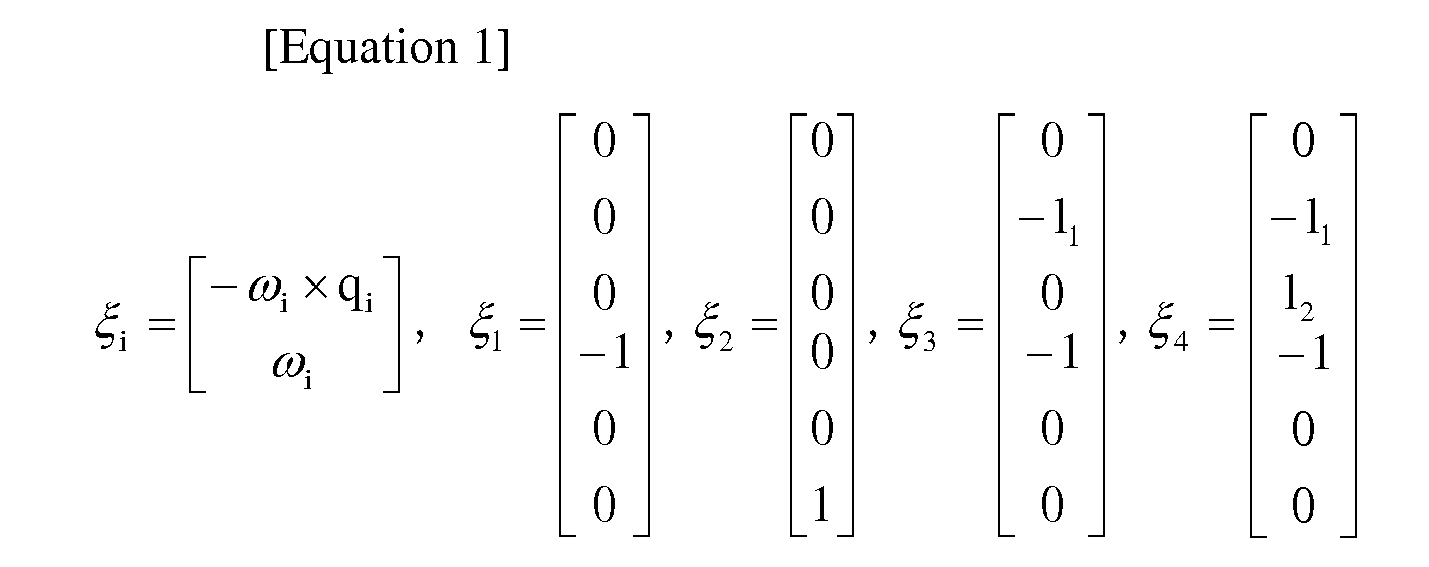
- When relative positions of centers of mass of the
respective links small link 35 between the first joint 13 and the twistjoint portion 19 is set to be (0, 0, r0), a center of mass position of the secondsmall link 36 between the twistjoint portion 19 and the second joint 14 is (0, 0, l0+r1), a center of mass position of thesecond link 17 between the second joint 14 and the third joint 15 is (0, r2, l1), a center of mass position of thethird link 18 is (0, l2+r3, l1), and an angular velocity is 0, the relative positions are expressed by the following Equation (2). -

Next, a Jacobian matrix of a position and posture is expressed by the following Equation (3). -

Here, si represents sin (θi), ci cos (θi), sij sin (θi+θj), cij cos (θi+θj), and Iii represents moment of inertia. Since the equation becomes complicated, representation of J411, J412, J421, and J431 are omitted. Since Mi* represents calculation of an inertia tensor with respect to a coordinate system with the center of gravity of each link being set as the original point, an off-diagonal term is 0. Further, the equation (3) is eventually expressed by a form of the following Equation (4) by utilizing a Lagrange method etc. -

joint portion 19, K3 a torsion spring constant of the second joint 14, and K4 a torsion spring constant of the third joint 15. In addition, torque of each actuator is simple since it is two variables of τ1 and τ2 as represented in Equation (4) as compared with a case of driving therespective joints - Next, will be explained specifically a control content of the
finger portion 12A of theactual robot hand 8 in line with a principle represented by the above-described equation of motion. As mentioned above, the actuator that drives the first joint 13 is the firstjoint drive motor 24, and this firstjoint drive motor 24 is provided with a control device (not shown in particular) that outputs a motor current. This control device inputs a deviation signal of a first joint command calculated by the PC3 based on the above-described equation of motion and angle information by an encoder (not shown in particular) of themotor 24, outputs the corresponding motor current, and thereby drives the firstjoint drive motor 24. Drive force of the firstjoint drive motor 24 corresponds to actuator torque τ1, and controls flexion operation in the first joint 13. It is to be noted that this actuator torque τ1 corresponds to one example of first drive force described in each claim. - In addition, actuators that drive the second joint 14 are the second
joint drive motor 25, and gears 30 and 31, and an actuator that drives the third joint 15 is the secondjoint drive motor 25. Similarly to the above, a deviation signal of a second joint command calculated by the PC3 and angle information by an encoder (not shown in particular) of the secondjoint drive motor 25 is input to a control device (not shown) provided at the secondjoint drive motor 25, the corresponding motor current is input, and the secondjoint drive motor 25 is driven. Drive force of the secondjoint drive motor 25 corresponds to actuator torque τ2, and controls flexion operation in the second joint 14 and the third joint 15. It is to be noted that this actuator torque τ2 corresponds to one example of second drive force described in each claim. - Namely, the second
joint drive gear 30 fixed to the output shaft of the secondjoint drive motor 25 drives the second joint drivengear 31 fixed to the secondjoint shaft 22. That is, the secondjoint drive motor 25 transmits the actuator torque τ2 to thesecond link 17 through the secondjoint drive gear 30 and the second joint drivengear 31, and flexes thesecond link 17 centering on the secondjoint shaft 22. It is to be noted that the secondjoint drive gear 30 and the second joint drivengear 31 correspond to one example of a gear mechanism described in each claim, and also correspond to one example of a drive transmission mechanism for a second link. - In addition, the second
joint drive gear 30 fixed to the output shaft of the secondjoint drive motor 25 drives the second joint drivengear 31 fixed to the secondjoint shaft 22, further drives the thirdjoint drive pulley 32 and thebelt 34, and transmits force to the third joint drivenpulley 33 fixed to the thirdjoint shaft 23. That is, the secondjoint drive motor 25 also transmits the actuator torque τ2 to thethird link 18 through the secondjoint drive gear 30, the second joint drivengear 31, the thirdjoint drive pulley 32, thebelt 34, and the third joint drivenpulley 33, and flexes thethird link 18 centering on the thirdjoint shaft 23. It is to be noted that the thirdjoint drive pulley 32, the third joint drivenpulley 33, and thebelt 34 correspond to one example of a pulley mechanism described in each claim, and that these and the secondjoint drive gear 30 and the second joint drivengear 31 correspond to one example of a drive transmission mechanism for a third link described in each claim. - As explained above, the embodiment has such a structure that at least one
link 16 of any one offinger portion 12A of a plurality offinger portions robot hand 8 is separated into the twosmall links small links small links finger portion 12A. As a result of this, since a degree of freedom due to the above-described torsional displacement increases by a single degree, thefinger portion 12A provided with the separatedlink 16 can operate not only in a grasp direction approaching the object to be grasped 9 and in a release direction moving away from theobject 9 as mentioned above, but can perform movement so that an angle toward theobject 9 is changed to change posture opposed to theobject 9. At least onefinger portion 12A provided with the shape-fitting mechanism US that allows for such a movement, and thereby therobot hand 8 in the embodiment can perform flexible grasping following a shape of theobject 9 with respect thereto than in a structure of a prior art. It is to be noted that by providing an additional actuator, it also becomes possible, for example, to make therobot hand 8 approach/move away from theobject 9 at an angle conforming to a curved surface shape of a surface of theobject 9, to make it move along the surface of theobject 9, or to make it approach/move away from theobject 9 in a state where posture is twisted obliquely to theobject 9, etc. - In addition, particularly in this embodiment, the relative rotations of the two
small links twist mechanism 38 along with the rotation of theshaft 42 are guided by theguide bar 45 and theguide groove 47 of theguide plate 43. As a result, thesmall link 35 of one side and thesmall link 36 of the other side are relatively displaced more smoothly, and thereby smoother movement of thefinger portion 12A provided with the twosmall links - In addition, particularly in this embodiment, the amounts of rotation in the relative rotation directions of the
small links shaft 42 are regulated within the predetermined ranges by the above-describedguide groove 47 of thetwist mechanism 38. As a result, the relative displacement of thesmall link 35 of the one side and thesmall link 36 of the other side is suppressed within a certain range, and therobot hand 8 can be controlled not to take improper posture and not to perform unnatural operation. As a result of this, smoother movement is achieved, and durability and reliability can also be improved. - In addition, particularly in this embodiment, the
torsion spring 46 of thetwist mechanism 38 provides the return force that displaces to the reverse rotation direction the twosmall links shaft 42. As a result, after the twosmall links object 9, passive stable grasping operation conforming to the shape of theobject 9 can be achieved. In addition, by the passive operation, a contact area with theobject 9 increases between thethird link 18 of the fingertip and thefirst link 16 of the base, and also thereby stable grasp can be performed. In addition, when the graspedobject 9 is released, the twosmall links - In addition, particularly in the embodiment, the
first link 16 of thepalm portion 11 side is configured with the twosmall links finger portion 12A can be performed. In addition, while thefirst link 16 is oscillated (flexed and extended) by the actuator torque τ1 from the firstjoint drive motor 24 arranged at thepalm portion 11, thesecond link 17 and thethird link 18 are oscillated (flexed and extended) by the actuator torque τ2 of the two-joint drive motor 25 arranged at the first link. As a result, thefirst link 16, and thesecond link 17 and thethird link 18 can be mutually independently oscillated (flexed and extended). - In addition, the second
joint drive motor 25 is arranged at the secondsmall link 36 of thesecond link 17 side, and while transmitted to thesecond link 17 by the secondjoint drive gear 30 and the second joint drivengear 31, the actuator torque τ2 from the secondjoint drive motor 25 is transmitted also to thethird link 18 by the thirdjoint drive pulley 32, thebelt 34, and the third joint drivenpulley 33. By commonizing the actuator for oscillating thesecond link 17 and the actuator for oscillating thethird link 18, as compared with a case of driving the joints by each independent actuator, load of actuator drive control can be reduced, and the links can be oscillated (flexed and extended) at a higher speed. At this time, the above-described thirdjoint drive gear 30, third joint drivengear 31, thirdjoint drive pulley 32,belt 34, and third joint drivenpulley 33 can transmit the actuator torque τ2 from the secondjoint drive motor 25 to thethird link 18. As a result, thethird link 18 can be smoothly driven by the underactuated mode of thesecond link 17, and natural flexion operation like human that works with flexion operation of thesecond link 17 can be achieved. - Further, the actuators for driving the
second link 17 and thethird link 18 are commonized as one secondjoint drive motor 25 as described above, and the firstjoint drive motor 24 for driving thefirst link 16 is arranged at thepalm portion 11, whereby the actuator arranged at thefinger portion 12A is only one secondjoint drive motor 25. As a result of this, weight reduction of thewhole finger portion 12A can also be achieved. - In addition, in this embodiment, the through-
hole 48 for making penetrate thecable member 49 to the secondjoint drive motor 25 is provided at theshaft 42, and thereby thecable member 49 of the secondjoint drive motor 25 that is arranged at the secondsmall link 36 of thesecond link 17 side can be smoothly disposed at thepalm portion 11 without being exposed to the outside of therobot hand 8. In addition, as a result, a power amplifier of the actuator can be arranged at thepalm portion 11, and also thereby weight reduction of thefinger portion 12A can be achieved. - It is to be noted that although in the above-described embodiment, only the
first link 16 in onefinger portion 12A of the threefinger portions robot hand 8 has a configuration capable of relative torsional displacement, the present invention is not regulated to this. For example, the plurality of (or all)finger portions 12 may have the configuration, or thelinks first link 16 may have it. - It is to be noted that the present invention is not regulated to the above-described embodiment, and that various modifications can be made without departing from the subject matter and the technical idea of the invention. Hereinafter, such modified examples will be explained in order.
- In the above-described embodiment, the return force of displacing the second
small link 36 and the firstsmall link 35 in thetwist mechanism 38 in the reverse rotation direction with respect to the relative torsional displacement therebetween is obtained by thetorsion spring 46, but the present invention is not regulated to this. For example, a configuration may be employed in which the above-described return force is obtained by the tension spring spanned between theguide plate 43 and theguide bar 45. - In
Fig. 7 , atwist mechanism 38A of the modified example is not provided with thetorsion spring 46 in the above-described embodiment, and instead, it is provided with twohelical springs 51. These twohelical springs 51 are spanned between the corresponding ends on the fingertip side (front side in the drawing) of theguide bar 45 and ends of theguide groove 47 that are initial positions of thehelical springs 51, and always provide biasing force to pull theguide bar 45 to the respective ends. It is to be noted that thehelical spring 51 corresponds to one example of a spring member described in each claim and one example of the return force providing member. - Also in the modified example, passive stable grasping operation and return to the original state after grasp release can be performed utilizing the biasing force due to elasticity of the
helical spring 51, thus enabling to obtain an effect similar to that of the above-described embodiment. - In addition, the above-described return force in the twist mechanism may be obtained using a permanent magnet. In
Fig. 8 , atwist mechanism 38B of the modified example is not provided with thetorsion spring 46 in the above-described embodiment, and instead, apermanent magnet 52 is provided on respective surfaces opposed to each other of theshaft support plate 41 and theguide plate 43. In so doing, magnetic poles (a north pole and a south pole) of eachpermanent magnet 52 is arranged so that the pair ofpermanent magnets 52 opposed to each other mutually exerts attraction force in a state where theshaft support plate 41 and theguide plate 43 are located at initial relative rotation positions. - As a result, since the opposing
permanent magnets 52 has a combination of the north pole and the south pole, or of the south pole and the north pole, always provide force of trying to return theshaft support plate 41 and theguide plate 43 to the initial positions. It is to be noted that in order that magnetic force sufficiently affects the opposingpermanent magnets 52, in this example, ashaft 42B and aguide bar 45B are formed comparatively short, and theshaft support plate 41 and theguide plate 43 are arranged so as to be sufficiently close to each other. In addition, it is preferable to respectively use a non-magnetic material with a low density, for example, aluminum, for each member of theshaft support plate 41, theshaft 42B, theguide plate 43, and theguide bar 45B that constitute thetwist mechanism 38B. It is to be noted that thepermanent magnet 52 corresponds to one example of the return force providing member described in each claim. - In the modified example, passive stable grasping operation and return to the original state after grasp release can be performed utilizing the attraction force with which the pair of
permanent magnets - In addition, the above-described return force may be obtained using a rubber member. In
Figs. 9A and 9B , atwist mechanism 38C of the modified example has: theshaft support plate 41; theshaft 42; a rubbermember storage body 53; acoupling member 54, two pressingmembers 55, and tworubber members 56. Theshaft support plate 41 and theshaft 42 are formed and fixed equal to those of the above-described embodiment, respectively. The whole rubbermember storage body 53 is formed in a columnar shape with a substantially same diameter as that of theshaft support plate 41, and theshaft 42 penetrates an axial center of the rubbermember storage body 53 to be supported rotatably. - In addition, two arc-shaped
deep grooves 57 that respectively make a same inner circumferential angle with the axial center of the rubbermember storage body 53 are formed in the rubbermember storage body 53, and arubber member 56 having a substantially same arc shape as thedeep groove 57 and formed long in the axial direction is stored inside eachdeep groove 57. Gap is provided among ends of therubber member 56 and thedeep groove 57 corresponding to one another in a combination thereof, and the pressingmember 55 with a flat plate shape is inserted in the gap, respectively. An end on the fingertip side (the front side inFig. 9A , and the right side inFig. 9B ) of each pressingmember 55 projects from an end of the rubbermember storage body 53, respectively, and it is fixed to a free end of theshaft 42 through thecoupling member 54 with a flat plate shape. Additionally, when thetwist mechanism 38C of the modified example is provided inside thefirst link 16, theshaft support plate 41 is fixed to the first small link 35 (together with theshaft 42 and the pressing member 55), and the rubbermember storage body 53 is fixed to the secondsmall link 36. It is to be noted that therubber member 56 corresponds to one example of the return force providing member described in each claim. - In the
coupling member 54 and the twopressing members 55 rotating around the axis of rotation of theshaft 42 together with theshaft 42, the twopressing members 55 press eachrubber member 56 in the rotational direction in thedeep grooves 57, respectively. In this case, restoring force of eachrubber member 53 provides to each pressingmember 55, thecoupling member 54, theshaft 42, and theshaft support plate 41 biasing force of displacing them in the reverse rotation direction, respectively. It is to be noted that each pressedrubber member 56 is elastically deformed so as to extend along a direction of the axis of rotation as shown with a dashed line inFig. 9B , and that this amount of elastic deformation is decided by a Poisson's ratio of a material of therubber member 56. - As described above, in the modified example, passive stable grasping operation and return to the original state after grasp release can be performed utilizing the return force of the
rubber member 56 after elastic deformation, thus enabling to obtain an effect similar to that of the above-described embodiment. In addition, since therubber member 56 is provided with not only elasticity but viscosity, some degree of guide function and restriction function for amount of rotation with respect to the relative rotation of the twosmall links guide bar 45 and theguide groove 47 in the above-described embodiment. It is to be noted that a resin member capable of similar elastic deformation can also be substituted for the above-describedrubber member 56. - Next, a second embodiment will be explained. In the embodiment, a robot hand can grasp an object in an enclosing manner in any posture by providing auxiliary torque by a spring member.
- Since configurations of the
robot device 1 and therobot body 2 provided with arobot hand 108 in accordance with the embodiment are similar to those of the above-mentioned first embodiment (Fig. 1 ), explanation thereof will be omitted. - In
Fig. 10 , therobot hand 108 has apalm portion 111 and threefinger portions 112 having bases coupled to thepalm portion 111. In eachfinger portion 112, threelinks link 116 of the base side is coupled to the first joint 113, and eachfinger portion 112 can perform flexion and extension operation like oscillation on one flat surface. The threefinger portions 112 are flexed so as to be close to one another, and thereby therobot hand 108 can grasp theobject 9 with the threelinks finger portions 112. Additionally, therobot hand 108 of the embodiment is provided with an underactuated mechanism that interlockingly drives adjacent two joints of the above-described threefinger portions 112 by one electric motor. - Next, an internal structure of the
whole finger portion 112 provided with the above-mentioned underactuated mechanism will be explained usingFig. 11 . It is to be noted thatFig. 11 shows a skin of a part of thepalm portion 111 with the hollow structure and the each links 116, 117, and 118.Fig. 11 shows a state where a wall portion, etc. are appropriately omitted. - In
Fig. 11 , a base of thefirst link 116 is fixed to a firstjoint shaft 1131 provided at an edge portion of thepalm portion 111, and the firstjoint shaft 1131 and an output shaft of a first motor 119 (actuator) are coupled by acoupling 121A. The firstjoint shaft 1131 is rotatably supported by abearing 126A provided at thepalm portion 111. According to such a configuration, thewhole finger portion 112 is oscillated (flexed and extended) at the first joint 113 with respect to thepalm portion 111 by torque generated by thefirst motor 119. - A second motor 120 (actuator) is installed on the fingertip side of the
first link 116. An output shaft of thesecond motor 120 and a secondjoint shaft 1141 are coupled by acoupling 121B. The secondjoint shaft 1141 is rotatably supported by abearing 126E provided at a base of thesecond link 117, and abearing 126B provided at thefirst link 116. In addition, adrive pulley 122 is fixed to the secondjoint shaft 1141, and rotation angles of thedrive pulley 122 and the secondjoint shaft 1141 coincide with each other. - The
third link 118 is coupled to a fingertip side of thesecond link 117. A base of thethird link 118 is fixed to a thirdjoint shaft 1151. The thirdjoint shaft 1151 is rotatably supported by abearing 126D provided at the fingertip side of thesecond link 117. A drivenpulley 123 is provided at the thirdjoint shaft 1151. Abelt 124 is spanned between thedrive pulley 122 and the drivenpulley 123, and torque of thedrive pulley 122 is transmitted to the drivenpulley 123 through thebelt 124. Anidle pulley 125 provided at an intermediate portion of thesecond link 117 is also in contact with thebelt 124. Thisidle pulley 125 plays a role to adjust tension of thebelt 124. It is to be noted that thedrive pulley 122, the drivenpulley 123, and thebelt 124 correspond to one example of a torque transmission mechanism described in the claims. - At a point where the
first link 116 and thesecond link 117 overlap with each other in the second joint 114, provided is astopper 128 that regulates posture of thesecond link 117 with respect to thefirst link 116. Thisstopper 128 is configured with apin 128A provided at thefirst link 116, and aguide groove 128B provided at thesecond link 117. In addition, at a point where thesecond link 117 and thethird link 118 overlap with each other in the third joint 115, astopper 129 that regulates posture of thethird link 118 with respect to thesecond link 117. Thisstopper 129 is configured with apin 129A provided at thesecond link 117, and aguide groove 129B provided at thethird link 118. - One example of a configuration of the
stopper 129 will be explained with reference toFigs. 12 and 13 . In theseFigs. 12 and 13 , at a point where thesecond link 117 and thethird link 118 overlap with each other, thepin 129A is installed upright inside thesecond link 117. At a point where thethird link 118 and thesecond link 117 overlap with each other, theguide groove 129B is provided at thethird link 118 so as to be parallel to an outer circumference centering on the thirdjoint shaft 1151, and is configured so as to be able to restrict an operation range of the insertedpin 129A. Namely, thestopper 129 regulates posture of thethird link 118 with respect to thesecond link 117 so that an axial line of thesecond link 117 and an axial line of thethird link 118 do not extend to not less than 180 degrees centering on the thirdjoint shaft 1151 as shown inFig. 12 , and so that the axial line of thesecond link 117 and the axial line of thethird link 118 are not flexed at an acute angle (for example, not more than 90 degrees) centering on the thirdjoint shaft 1151 as shown inFig. 13 . It is to be noted that thestopper 128 also has the configuration similar to that of the above-describedstopper 129. - Returning to
Fig. 11 , acoiled torsion spring 127 is provided around the secondjoint shaft 1141. Although illustration is omitted, one end of thetorsion spring 127 is fixed to thefirst link 116, and the other end thereof is fixed to thesecond link 117. As a result, thetorsion spring 127 provides auxiliary torque to the second joint 114 so that drive torque required for driving the second joint 114 is smaller than drive torque required for driving the third joint 115 in grasping operation being performed, and so that the drive torque required for driving the second joint 114 is larger than the drive torque required for driving the third joint 115 in grasp release operation being performed. - One example of a configuration of the
torsion spring 127 will be explained (Fig. 14 ). It is to be noted that illustration of thestopper 128 is omitted inFig. 14 . InFig. 14 , thetorsion spring 127 is inserted around the secondjoint shaft 1141. One of free ends of thetorsion spring 127 is fixed to apin 135A provided inside thefirst link 116, and another free end of thetorsion spring 127 is fixed to apin 135B provided inside thesecond link 117. Thepins second link 117 is flexed, for example, at 90 degrees with respect to thefirst link 116 in a natural state where thesecond motor 120 is not turned on. It is to be noted that thetorsion spring 127 corresponds to one example of a drive torque adjusting member described in the claims, and also corresponds to one example of the second spring member. - Next, operation of the
finger portion 112 of therobot hand 108 in accordance with the embodiment will be explained with reference toFig. 11 . Themotor 119 drives the firstjoint shaft 1131 and performs posture control of thefirst link 116, and themotor 120 drives the secondjoint shaft 1141 and the thirdjoint shaft 1151. Since themotor 120, the secondjoint shaft 1141, and the thirdjoint shaft 1151 are underactuated mechanisms, themotor 120 cannot arbitrarily perform angle control of the thirdjoint shaft 1151. The underactuated mechanism is a mechanism with smaller actuator degree of freedom than a degree of freedom of an object to be controlled. A point where an input degree of freedom is smaller than this output degree of freedom is advantageous to following grasp (grasp so as to follow a shape of the object). In the embodiment, two joint shafts are provided for one motor. In an object grasping process, themotor 119 performs posture control of thefirst link 116 so that thefirst link 116 first approaches the object to be grasped 9. After the first link is controlled to be predetermined posture, themotor 120 drives thesecond link 117 and the third link so that thesecond link 117 and thethird link 118 get contact with the object to be grasped 9. The underactuated mechanism (themotor 120 drives thesecond link 117 and the third link 118) of the embodiment will be explained in detail. When friction occurs among thedrive pulley 122, the drivenpulley 123, and thebelt 124, and motor torque exceeding the friction is generated, thethird link 118 rotates around the thirdjoint shaft 1151. This will be called rotation operation. When motor torque smaller than the friction is generated, thesecond link 117, thethird link 118, thebelt 124, thedrive pulley 122, and the drivenpulley 123 integrally rotate around the secondjoint shaft 1141. This will be called revolution operation. By the rotation operation and the revolution operation, two joints can be driven by one motor. When speed control of thesecond motor 120 is performed, and the output shaft of thesecond motor 120 rotates clockwise seen from the right side inFig. 11 (in a paper-based depth direction of a fingertip side inFig. 11 ), the secondjoint shaft 1141 and thedrive pulley 122 similarly rotate clockwise through thecoupling 121B. When the revolution operation is continued until thesecond link 117 gets contact with the object to be grasped 9, and thesecond link 117 gets contact with the object to be grasped 9, motor velocity deviation becomes large, and therefore torque exceeding friction is generated so that the velocity deviation becomes small, and the revolution operation is shifted to the rotation operation. That is, after thesecond link 117 gets contact with the object to be grasped 9, thethird link 118 is flexed toward the object. By a series of operation (rotation operation and revolution operation), thefinger portion 112 of the present invention grasps the object to be grasped 9 following the shape of the object. - An order with which each link (the
second link 117 and the third link 118) starts to move is important in order to stably grasp the object to be grasped 9 with the hand, and an order during flexion operation is carried out with thethird link 118 after thesecond link 117, and an order during extension operation is carried out with thesecond link 117 after thethird link 118. Thetorsion spring 127 and thestopper 129 are provided in order to reliably perform the operation. It is to be noted that thesecond link 117 may start extension in the middle of extension of thethird link 118. - First, a reason why the
torsion spring 127 is provided around the second joint shaft 141 will be explained. Thetorsion spring 127 works with little torque at the time of flexion operation so that thethird link 118 starts to move after thesecond link 117, and works so that thesecond link 117 starts to move after thethird link 118 unless large torque is provided at the time of extension operation. By addition of thetorsion spring 127, desired flexion and extension operation can be achieved even in any posture. Thestopper 129 is a part required for extension operation, and if a torsion spring is added and there is nostopper 129, only thethird link 118 works and the second link cannot be moved. That is, desired extension operation cannot be realized without thestopper 129. Further, in thesecond link 117 continuing extension operation, thestopper 128 restricts the secondjoint shaft 1141 so that an angle between thesecond link 117 and thefirst link 116 does not become not less than a certain set angle (for example, 180 degrees) centering on the secondjoint shaft 1141. - Next will be explained an initial posture control method in driving the
second motor 120. By biasing force of thetorsion spring 127, thesecond link 117 is in flexion posture (posture in a grasp direction) when a brake is not applied in a case where power supply of thesecond motor 120 is not on. Namely, an initial state of thesecond link 117 corresponds to the flexion posture under the influence of thetorsion spring 127. However, when grasping the object, thesecond link 117 and thethird link 118 is preferably in extension posture. Consequently, a voltage command is issued from the PC3 to thesecond motor 120 so as to rotate counterclockwise seen from the right side inFig. 11 (in a paper-based front direction of a fingertip side inFig. 11 ), and torque that resists the biasing force of thetorsion spring 127 is generated to carry out extension operation of thesecond link 117. At this time, extension operation of thethird link 118 is stopped by thestopper 129 and further, extension operation of thesecond link 117 is stopped by thestopper 128. The state where thefirst link 116, thesecond link 117, and thethird link 118 are extended in series is set as initial posture, and the state is stored in a memory of the PC3 as an initial angle 0 degree of thesecond motor 120. In addition, an angle before power-on and an angular difference (a rotation angle) at the time of being constrained by thestopper 128 are also stored in the PC3. An angular difference 0 is utilized to return the robot hand to the initial posture after the power-on, and the initial posture can be kept easily by issuing the angular difference as a target angle command. - According to the
robot hand 108 in accordance with the second embodiment described above, the shape-fitting mechanism US having the drivepulley 122, the drivenpulley 123, thebelt 124, and thetorsion spring 127 as the torque transmission mechanism is provided at thefinger portion 112, and in performing grasping operation, flexion drive of the second joint 114 is performed prior to the third joint 115, and in performing grasp release operation, extension of the third joint 115 is driven prior to thesecond joint 114. Thetorsion spring 127 enough to hold self-weights of thesecond link 117 and thethird link 118 is selected, and thereby flexible grasping following the shape of the object to be grasped 9 can be performed by thefinger portion 112 even in any posture. In addition, even in any posture, flexion and extension can be switched only by the rotational direction of thesecond motor 120. Further, since the number of motors is only one, and there are few parts for transmission of force, weight reduction of the whole finger portion can be achieved, and high-speed operation of the fingers can also be performed. - In addition, particularly in the embodiment, the
stopper 129 that regulates the posture of thethird link 118 with respect to thesecond link 117 is provided at thefinger portion 112. As a result, in carrying out grasp release operation, thethird link 118 first starts extension, operation of thethird link 118 is stopped at a predetermined angle and subsequently, thesecond link 117 can be extended. Namely, extension operation of thesecond link 117 can be reliably started after the extension of thethird link 118. - It is to be noted that the present invention is not regulated to the above-described embodiment, and that various modifications can be made without departing from the subject matter and the technical idea of the invention. Hereinafter, such modified examples will be explained in order.
- Although in the above-described second embodiment, the
second motor 120 is arranged outside thesecond link 116 so that the output shaft of thesecond motor 120 and the secondjoint shaft 1141 coincide with each other, it is more preferable for thesecond motor 120 to be arranged so as not to interfere with theother finger portions 112. Accordingly, thesecond motor 120 may be arranged inside thefirst link 116. The modified example will be explained with reference toFig. 15 . However, only components related to arrangement of thesecond motor 120 will be explained. - In
Fig. 15 , thesecond motor 120 of the modified example is fixed to the inside of thefirst link 116. Anoutput shaft 131 of thesecond motor 120 is supported by abearing 132A arranged at the skin of thefirst link 116, and agear 130A is coupled to thisoutput shaft 131. Agear 130C is coupled to the secondjoint shaft 1141 in parallel with thedrive pulley 122. Agear 130B (idle gear) is arranged inside thefirst link 116 so as to mesh with thesegears idle gear shaft 133 that is coupled to thegear 130B is supported by abearing 132B arranged at the skin of thefirst link 116. The other configurations are similar to those of the above-described second embodiment. - Next, operation will be explained. When the
output shaft 131 of thesecond motor 120 rotates clockwise seen from the right side inFig. 15 (in a paper-based depth direction of a fingertip side inFig. 15 ), thegear 130A similarly rotates clockwise, and thegear 130B meshing with thegear 130A rotates counterclockwise. Thegear 130C meshing with thegear 130B rotates clockwise. As a result, the secondjoint shaft 1141 coupled to thegear 130C also rotates clockwise. Subsequent operation is similar to that of the above-mentioned second embodiment, and thesecond link 117 and thethird link 118 are flexed in the paper-based depth direction in that order, and take operation to grasp the object to be grasped 9. In addition, when thesecond motor 120 rotates counterclockwise seen from the right side inFig. 15 (in a paper-based front direction on the fingertip side inFig. 15 ), the secondjoint shaft 1141 rotates counterclockwise together with thegear 130C similarly to the above. As a result, thethird link 118 and thesecond link 117 extend in the paper-based front direction in that order. - Also according to the modified example, an effect similar to that of the above-described second embodiment is obtained. In addition, since the
torsion spring 127 can be installed both ends of the secondjoint shaft 1141 as shown inFig. 15 because of unnecessity of providing thecoupling 121B, auxiliary torque can be increased. It is to be noted that although in the modified example, thegear 130B is provided n order to make the same a rotational direction of thesecond motor 120 and rotational directions of the second joint 114 and the third joint 115, thegear 130B may be eliminated f it is not necessary to coincide the rotational directions thereof. In this case, further weight reduction can be achieved. - The modified example is an example where a worm gear is used instead of a spur gear in the configuration of the above-described modified example (2-1). The modified example will be explained with reference to
Fig. 16 . - In
Fig. 16 , thesecond motor 120 is arranged inside thefirst link 116 so that an axial direction thereof may conform to a link longitudinal direction. Theoutput shaft 131 of thesecond motor 120 is coupled to aworm 134, and thisworm 134 is supported bybearings first link 116. Thegear 130A is arranged so as to mesh with theworm 134, and thegear 130B is arranged inside thefirst link 116 so as to mesh with thegears gear 130C is coupled to the secondjoint shaft 1141 in parallel with thedrive pulley 122 similarly to the one explained in the above-described modified example (2-1). - Next, operation will be explained. When the
worm 134 rotates counterclockwise seen from the upper side inFig. 16 by drive of thesecond motor 120, thegear 130A rotates counterclockwise, thegear 130B clockwise, and thegear 130C counterclockwise. As a result, when the secondjoint shaft 1141 rotates counterclockwise similarly to thegear 130C, thesecond link 117 and thethird link 118 are flexed. On the contrary, when theworm 134 rotates clockwise seen from the upper side inFig. 16 , thesecond link 117 and thethird link 118 are extended. - Also according to the modified example, an effect similar to that of the above-described second embodiment is obtained. In addition, by using the
worm 134, an effect of reducing power consumption of thesecond motor 120 for keeping the posture of thesecond link 117 and thethird link 118 can also be obtained. - Although the
torsion spring 127 provides auxiliary torque to the second joint 114 in the above-described second embodiment, a tension spring may be used instead of thetorsion spring 127. The modified example will be explained with reference toFig. 17 . - In
Fig. 17 , one end of afirst wire 138A is fixed to thepin 135A provided inside thefirst link 116, and the other end of thefirst wire 138A is coupled to an end of a coiledtension spring 137. Another end of thetension spring 137 is coupled to asecond wire 138B, and thesecond wire 138B is fixed to thepin 135B provided inside thesecond link 117. A part of thefirst wires 138A is in a state of being in contact with apulley 139 rotatably supported by the secondjoint shaft 1141. Thispulley 139 is installed in parallel with thedrive pulley 122. In this case as well, as for natural state posture when thesecond motor 120 is not turned on, thepins second link 117 is flexed at 90 degrees with respect to thefirst link 116. Also according to the modified example, an effect similar to that of the above-described second embodiment is obtained. It is to be noted that thetension spring 137 corresponds to one example of the drive torque adjusting member described in the claims, and also corresponds to one example of the second spring member. - Although the case where each
finger portion 112 is configured with the threelinks Figs. 18 to 21 . - In
Fig. 18 , therobot hand 108 has such a configuration that thefinger portion 212 corresponding to a thumb couples twolinks link 216 on the palm side is coupled to thepalm portion 111 through the first joint 213. Configurations of the other twofinger portions 112 are the same as those of the above-described second embodiment. Thefinger portion 212 can perform flexion operation on one flat surface oblique to oscillating surfaces of theother finger portions 112. These threefinger portions robot hand 108 can grasp the object to be grasped 9. - In
Fig. 19 , at the edge portion of thepalm portion 111, an output shaft of the first motor 219 (actuator) and a firstjoint shaft 2131 are coupled to each other by acoupling 221. The firstjoint shaft 2131 is rotatably supported by abearing 226A provided at thepalm portion 111 and abearing 226C provided at thefirst link 216. According to such a configuration, thewhole finger portion 212 is flexed at the first joint 213 with respect to thepalm portion 111 by torque generated by thefirst motor 219. - A principle that the first
joint shaft 2131 and a secondjoint shaft 2141 are respectively driven by thefirst motor 219 is similar to a principle inFig. 11 that thesecond motor 219 drives the secondjoint shaft 1141 and the thirdjoint shaft 1151, respectively. - The
second link 217 is coupled to a fingertip side of thefirst link 216. A base of thesecond link 217 is fixed to the secondjoint shaft 2141. This secondjoint shaft 2141 is rotatably supported by abearing 226B provided on the fingertip side of thefirst link 216. A drivenpulley 223 is provided at the secondjoint shaft 2141. Abelt 224 is spanned between adrive pulley 222 and the drivenpulley 223, and torque of thedrive pulley 222 is transmitted to the drivenpulley 223 through thebelt 224. It is to be noted that thedrive pulley 222, the drivenpulley 223, and thebelt 224 correspond to one example of the torque transmission mechanism described in the claims. - A coiled
torsion spring 227 is provided around both ends of the firstjoint shaft 2131. One end of eachtorsion spring 227 is fixed to thepalm portion 111, and the other end thereof is fixed to thefirst link 216. Even though thehand 108 takes any posture, thetorsion spring 227 acts so that the secondjoint shaft 2141 is driven subsequent to the firstjoint shaft 2131 at the time of flexion operation, and so that the firstjoint shaft 2131 is driven subsequent to the secondjoint shaft 2141 at the time of extension operation. Thetorsion spring 227 provides auxiliary torque to the first joint 213. - A
stopper 228 that regulates posture of thefirst link 216 with respect to thepalm portion 111 is provided at the first joint 213. Thisstopper 228 regulates the posture so that thepalm portion 111 and thefirst link 216 do not extend to not less than 180 degrees centering on the firstjoint shaft 2131. It is to be noted that at the time of flexion operation of thefirst link 216, thefirst link 216 gets contact with anend surface 1111 of thepalm portion 111, and thereby the posture is regulated so that thepalm portion 111 and thefirst link 216 do not flex at an acute angle (for example, not more than 90 degrees). At a point where thefirst link 216 and thesecond link 217 overlap with each other in the second joint 214, astopper 229 that regulates posture of thesecond link 217 with respect to thefirst link 216. Thisstopper 229 regulates posture so that thefirst link 216 and thesecond link 217 do not extend to not less than 180 degrees centering on the secondjoint shaft 2141, and they do not flex at an acute angle (for example, not more than 90 degrees). In addition, thestopper 229 acts to reliably drive the firstjoint shaft 2131 subsequent to the secondjoint shaft 2141 at the time of extension operation. Configurations of thesestoppers stopper - As described above, in the modified example, the shape-fitting mechanism US having the drive
pulley 222, the drivenpulley 223, thebelt 224, and thetorsion spring 227 as the torque transmission mechanism is provided at thefinger portion 212, and drive torque required for driving the first joint 213 is adjusted, whereby it becomes possible to grasp the object to be grasped in an enclosing manner by thefinger portions 212. - Next, other configuration examples of the
finger portion 212 will be explained usingFigs. 20 and21 . Although thefinger portion 212 corresponding to the thumb of therobot hand 108 has such a configuration that the twolinks Fig. 20 , unlike the example shown inFig. 19 , thefirst link 216 on the palm side is flexed on a flat surface substantially perpendicular to oscillating flat surfaces of the other twofinger portions 112 through the first joint 213, and thesecond link 217 can perform flexion operation through the second joint 214 on a flat surface parallel to the oscillating flat surface of thefinger portion 112. - A
bevel gear 230 is provided at the firstjoint shaft 2131 coupled to an output shaft of thefirst motor 219 by thecoupling 221. Thisbevel gear 230 similarly meshes with the bevel gear-shapeddrive pulley 222. Thebelt 224 is spanned between thedrive pulley 222 and the drivenpulley 223 provided at the secondjoint shaft 2141, and torque of thedrive pulley 222 is transmitted to the drivenpulley 223 through thebelt 224. It is to be noted that a point where the coiledtorsion spring 227 is provided around the firstjoint shaft 2131, and a point where thestoppers joint shaft 213 and the secondjoint shaft 214 are similar to the configuration shown inFig. 19 . - Next, operation of the
finger portion 212 will be explained also with reference toFig. 21 . It is to be noted thatFigs. 21A and 21B are views of therobot hand 108 seen from a wrist direction (lower side inFig. 20 ), and thatFig. 21C is a view thereof seen from a side surface direction (right side inFig. 20 ). When the output shaft of thefirst motor 219 rotates clockwise seen from the lower side inFig. 20 (clockwise inFig. 21 ), the firstjoint shaft 2131 and thebevel gear 230 similarly rotate clockwise through thecoupling 221. As a result, thefirst link 216 rotates together with the firstjoint shaft 2131, and thefirst link 216 is flexed from a state shown inFig. 21A to the object to be grasped 9 side (paper-based front side inFig. 20 ). When thepalm portion 111 and thefirst link 216 make 90 degrees with each other by flexion operation, as shown inFig. 21B , thefirst link 216 gets contact with theend surface 1111 of thepalm portion 111, and thereby flexion operation of thefirst link 216 is stopped. Further, when the output shaft of thefirst motor 219 rotates clockwise, torque of thefirst motor 219 is transmitted from thebevel gear 230 to the drivenpulley 223 through thedrive pulley 222 and thebelt 224, the secondjoint shaft 2141 rotates clockwise, and thesecond link 217 is flexed until it gets contact with the object to be grasped 9 as shown inFig. 21C . In a manner described above, since thefinger portion 212 contacts thesecond link 217 to the object to be grasped 9 subsequent to thefirst link 216, it turns out that thefinger portion 212 has performed operation following the object to be grasped 9. - Also according to the modified example explained above, an effect similar to that of the above-described second embodiment is obtained.
- Although inward rotation operation that brings the finger portions close to one another and outward rotation operation that keeps the finger portions away from one another do not considered in the above-described second embodiment, a configuration in which inward rotation/outward rotation operation can be performed may be employed in order that flexible grasping following a shape of an object to be grasped can be performed. The modified example will be explained with reference to
Figs. 22 to 29 . - In
Fig. 22 , arobot hand 300 has apalm portion 311 and threefinger portions palm portion 311. When thefinger portion 312 is explained as one example, thefinger portion 312 is configured with fourlinks base link 301 is coupled to agear 305, and thegear 305 meshes with agear 306. As a result, thebase link 301 oscillates on a flat surface parallel to thepalm portion 311 by adrive motor 307 of thegear 306. Similarly, agear 309 coupled to abase link 315 of thefinger portion 313 meshes with thegear 306 through agear 308. As a result, abase link 315 oscillates on the flat surface parallel to thepalm portion 311 by thedrive motor 307. Thegear 308 is provided so that rotational directions of thegear 305 and thegear 309 are opposite to each other (for example, so that thegear 309 rotates counterclockwise in thegear 305 rotating clockwise). Thefinger portion 314 oscillates on the flat surface parallel to thepalm portion 311 by adrive motor 310 coupled to abase link 316. - By employing such a configuration, inward rotation/outward rotation operation of the two
finger portions drive motor 307. Accordingly, as compared with a case of respectively providing a drive motor at each finger portion, the number of motors can be reduced, thus resulting in cost reduction. - Next, a structure of the
palm portion 311 will be explained usingFig. 23 . InFig. 23 , thebase link 301 is arranged between thepalm portion 311 and a back portion of thehand 317, and the above-describeddrive motor hand 317. Thepalm portion 311 and the back portion of thehand 317 are fixed to each other with a plurality ofbolts 318 with aspacer 350 being sandwiched therebetween. An output shaft of thedrive motor 307 is coupled to ashaft 320, and thisshaft 320 is supported by abearing 319 provided inside thepalm portion 311, and abearing 321 provided inside the back portion of thehand 317. Meanwhile, a shaft 322 coupled to thebase link 301 is also supported by thebearing 319 and thebearing 321. Additionally, thegear 306 coupled to theshaft 320 and thegear 305 coupled to the shaft 322 mesh with each other. - As described above, the
drive motors hand 317, and thereby motor replacement can be performed easily. - Next, a schematic structure of the inside of the finger portion will be explained using
Fig. 24 . It is to be noted that since thefinger portions finger portion 312, only thefinger portion 312 will be explained here. A motor 330 (actuator) is arranged inside thebase link 301, and an output shaft of themotor 330 is coupled to abevel gear 323. Thebevel gear 323 meshes with abevel gear 324 arranged coaxially with a firstjoint pulley 325. In order to transmit drive force of the firstjoint pulley 325 to a secondjoint pulley 327, abelt 326 is spanned between thepulleys joint pulley 327 to a thirdjoint pulley 329, abelt 328 is spanned between thepulleys motor 330 works as force of flexing/extending each link. - Although detailed description is omitted, here, a torsion spring (not shown) is provided at a first joint 331 and a
second joint 332 of thefinger portion 312. As a result, the torsion spring provides auxiliary torque to the first joint 331 and the second joint 332 so that drive torque required for driving the first joint 331 is smaller than drive torque required for driving the second joint 332 and a third joint 333, and so that the drive torque required for driving the second joint 332 is smaller than the drive torque required for driving the third joint 333, in grasping operation being performed, and also so that the drive torque required for driving the first joint 331 is larger than the drive torque required for driving the second joint 332 and the third joint 333, and so that the drive torque required for driving the second joint 332 is larger than the drive torque required for driving the third joint 333, in grasp release operation being performed. - In addition, although illustration is omitted, the stoppers similar to those of the above-mentioned second embodiment are provided between the
links links links - As described above, according to the modified example, the shape-fitting mechanism US having the
pulleys belts joints finger portion 312 by the torsion spring even in any posture. - Next, operation of the
robot hand 300 will be explained usingFigs. 25 to 28 . InFigs. 25 and 26 , a state is shown where the comparatively large object to be grasped 9 has been grasped by thehand robot 300. An image of the object to be grasped 9 in this case is, for example, an empty can. In grasping a side surface of the object to be grasped 9 by the threefinger portions robot hand 300 grasps the empty can following a shape thereof. - In
Figs. 27 and 28 , a state is shown where the comparatively small object to be grasped 9 has been grasped by thehand robot 300. In this example, the object to be grasped 9 is an object having a rectangular parallelepiped shape, and is grasped by the twofinger portions finger portions - It is to be noted that although the case where the object to be grasped 9 is grasped by the
finger portions finger portions finger portions finger portions - According to the modified example explained above, similarly to the above-mentioned second embodiment etc., it is possible to grasp the object to be grasped 9 in an enclosing manner by the
finger portions robot hand 300 can perform flexible grasping following the shape of the object to be grasped 9 with respect thereto. In addition, since three joints are driven by one motor, a weight of the finger portion can be reduced more than in the above-mentioned second embodiment, and cost can be reduced. - Next, an other configuration example of the
robot hand 300 will be explained usingFig. 29 . Although themotor 330 that oscillates (flexes and extends) the finger portion is incorporated in thebase link 301 in the above-described modified example, it is better to arrange themotor 330 outside thefinger portion 312 for weight reduction of thefinger portion 312. InFig. 29 , themotor 330 installed at the back portion of thehand 317 is coupled to theshaft 332, and on an axis of thisshaft 332, aworm 331 is coupled in thebase link 301. Inside thebase link 301, aworm wheel 333 is arranged so as to mesh with theworm 331. In addition, agear 334 is arranged in the middle of the inside of thebase link 301 in order to transmit rotation of theworm wheel 331 to the firstjoint pulley 325. Thegear 334 meshes with agear 335 arranged to be coaxial with the firstjoint pulley 325. As a result, thefirst link 302, thesecond link 303, and thethird link 304 can be oscillated (flexed and extended) by themotor 330 of the back portion of the hand. A bearing (not shown) is provided in thegear 305, and thegear 305 and thebase link 301 are coupled to each other so that torque of themotor 330 and torque of thegear 305 do not interfere with each other. The other configurations in which the first link, the second link, and the third link are driven are similar to those of the above-mentionedFig. 24 . - Such a configuration may be employed that a reduction device is also combined with the above-mentioned first motor and second motor. In that case, output torque becomes large. In addition, a wire made by winding a thin wire (made of metal or nylon) around a wire core may be used for a belt, and even if both ends of the wire are joined with metal via a drive pulley, a driven pulley, and an idle pulley to make a circle, the operation shown in the above can be achieved, and in this case, if a resin material is used for a drive pulley, a driven pulley, and an idle pulley, a drive transmission system becomes lightweight.
- Next, a third embodiment will be explained. In the embodiment, adjustment of drive torque required for driving joints is performed by constraining drive of a joint shaft on a fingertip side using a joint constraining mechanism included in the shape-fitting mechanism, and thereby an object can be grasped in an enclosing manner by fingers.
- Since configurations of the
robot device 1 and therobot body 2 provided with a robot hand in accordance with the embodiment are similar to those of the above-mentioned first embodiment (Fig. 1 ), and a configuration of the robot hand in accordance with the embodiment is similar to that of the above-mentioned second embodiment (Fig. 10 ), explanation thereof will be omitted. - Next, an internal structure of a
whole finger portion 400 included in the robot hand in accordance with the embodiment will be explained usingFigs. 30 and31 . First, aplanetary gear mechanism 401 included inside thefinger portion 400 will be explained usingFig. 30 . InFig. 30 , theplanetary gear mechanism 401 has: ashaft 4101 that inputs output torque from acoupling 409 to asun gear 4102; aplanetary gear 4103 that inputs output of thesun gear 4102 to acarrier 4104; acarrier cup 4105 provided at thecarrier 4104; theplanetary gear 4103 that inputs the output of thesun gear 4102 to aring gear 4106 in rotation of thecarrier cup 4105 being stopped; aring gear cup 4107 that has thering gear 4106 thereinside; abearing 4109 that rotatably supports thering gear cup 4107; and acase 4108 that protects theplanetary gear mechanism 401. In addition, cogs are provided at top surfaces of thecarrier cup 4105 and thecarrier cup 4107. It is to be noted that theplanetary gear mechanism 401 corresponds to one example of the torque transmission mechanism described in the claims. - Next, an internal structure of the
finger portion 400 will be explained usingFig. 31 . InFig. 31 , in thefinger portion 400, thecarrier cup 4105 of theplanetary gear mechanism 401 oscillates asecond link 417 through thegear 403 in a paper-based depth direction and a paper-based front direction inFig. 31 . However, by astopper 423, thesecond link 417 does not get warped in the paper-based front direction. Base sides of thegear 403 and thesecond link 417 are coupled to a secondjoint shaft 407 of asecond joint 425. Namely, thesecond link 417 rotates centering on the secondjoint shaft 425 by rotation of thegear 403, and thefinger portion 400 is flexed at thesecond joint 425. - Meanwhile, the
ring gear cup 4107 of theplanetary gear mechanism 401 rotates a thirdjoint shaft 420 of a third joint 424 through thegear 405,bevel gears shaft 416, andbevel gears third link 421 in the paper-based depth direction and the paper-based front direction. However, by astopper 423, thethird link 421 does not get warped in the paper-based front direction. Relative angle displacement of thegear 405 and thebevel gear 406 is constrained to be zero, and thesegears joint shaft 425. That is, although omitted on the paper, a bearing is incorporated inside thegear spring 422 is constrained so that a relative angle of thethird link 421 and thesecond link 417 is zero. Constraint of drive of the thirdjoint shaft 420 by thespring 422 is performed until thesecond link 417 gets contact with the object to be grasped 9 and rotation of the secondjoint shaft 407 is stopped, and thering gear cup 4107 maintains a rest state in the meantime. - Drive torque of the
planetary gear mechanism 401 is differential torque of two pairs of motors 413 (actuators), and is input to thesun gear 4102 of theplanetary gear mechanism 401 throughbevel gears shaft 410, and thecoupling 409. In addition, synthetic torque of two pairs ofmotors 413 is the torque for oscillating afirst link 414 around the firstjoint shaft 426 in the paper-based depth direction and the paper-based front direction. - Commonly, a planetary gear mechanism is a mechanism that fixes any one of a sun gear, a carrier, and a ring gear, and decelerates or accelerates output with respect to input. In the embodiment, the
sun gear 4102 serves as input and thecarrier 4104 and thering gear 4106 serve as output. However, as things stand, it is not determined which thecarrier 4104 and thering gear 4106 that serve as the output first start to move, or simultaneously move. Here, thering gear 4106 is indirectly constrained by thespring 422 so that the second joint 425 starts to move prior to the third joint 424 in grasping operation being performed. By constraining thering gear 4106 as described above, underactuated fingers by theplanetary gear mechanism 401 can also achieve following grasp. - As described above, in the embodiment, the
finger portion 400 is provided with thesun gear 4102, thecarrier 4104, and thering gear 4106, and provided is the shape-fitting mechanism US having: theplanetary gear mechanism 401 in which thecarrier 4104 is indirectly coupled to the secondjoint shaft 407, and thering gear 4106 is to the thirdjoint shaft 420; and thespring 422 that constrains rotation of the thirdjoint shaft 420 so that drive torque required for driving the secondjoint shaft 407 is smaller than drive torque required for driving the third joint shaft 420 (in other words, adjusts so as to increase drive torque of the third joint shaft) in grasping operation being performed, and it becomes possible to grasp the object to be grasped 9 by thefinger portion 400 by adjusting drive torque required for driving the third joint 424. It is to be noted that thespring 422 corresponds to one example of the drive torque adjusting member and the joint constraining mechanism described in the claims. - In addition, by using an interference mechanism, angle control of the
first link 414 is performed by the synthetic torque, and angle control of thesecond link 417 and thethird link 421 is performed by the differential torque. For example, a case is considered where one point of an inner circumference and one point of an outer circumference of a doughnut-shaped object (tape for packing, etc.) by the robot hand with two fingers. First, posture control of the first link is performed so that the two fingers are arranged at the inner circumference and the outer circumference of the doughnut-shaped object. Subsequently, posture control of the second and third links is performed, and thereby it becomes possible to grasp one point of the inner circumference and one point of the outer circumference of the doughnut-shaped object. In a manner described above, posture control can be achieved even in underactuation. - Next, an operating principle of the shape-fitting mechanism US in the
finger portion 400 will be explained usingFig. 32 . InFig. 32 , theplanetary gear mechanism 401 is provided with: thesun gear 4102; theplanetary gear 4103; thecarrier 4104; and thering gear 4106, and thering gear 4106 is indirectly constrained by thespring 422 as mentioned above. Thisspring 422 is arranged between thesecond link 417 and thethird link 421.Fig. 32A shows a state where input torque to thesun gear 4102 is zero. Next, as shown inFig. 32B , when clockwise torque is input to thesun gear 4102, theplanetary gear 4103 rotates, and simultaneously thecarrier 4104 similarly rotates clockwise. As a result, thesecond link 417 moves toward the object to be grasped 9 centering on the secondjoint shaft 407. At this time, since the thirdjoint shaft 420 is constrained by thespring 422, and thereby thering gear 4106 has stopped, a relative angle of thesecond link 417 and thethird link 421 is zero. Subsequently, when thesecond link 417 gets contact with the object to be grasped 9, drive of the secondjoint shaft 407 is constrained, and thecarrier 4104 is constrained. As a result, as shown inFig. 32C , counterclockwise torque occurs at thering gear 4106, and thethird link 421 moves toward the object to be grasped 9 centering on the thirdjoint shaft 420. When thefirst link 414, thesecond link 417, and thethird link 421 get contact with the object to be grasped 9, both thecarrier 4104 and thering gear 4106 are constrained, and thereby theplanetary gear 4103 and thesun gear 4102 are stopped. - According to the third embodiment described above, the shape-fitting mechanism US having the
planetary gear mechanism 401 and thespring 422 as the torque transmission mechanism is provided at thefinger portion 400, the second joint 425 and the third joint 424 are flexed in that order in grasping operation being performed, and it becomes possible to grasp the object to be grasped in an enclosing manner by thefinger portion 400 even in any posture by adjusting drive torque required for driving the third joint 424. As a result, the robot hand can perform flexible grasping following the shape of the object to be grasped 9 with respect thereto. - It is to be noted that the present invention is not regulated to the above-described embodiment, and various modifications can be made without departing from the subject matter and the technical idea of the invention. Hereinafter, such modified examples will be explained in order.
- Although the cogs are provided at the top surfaces of the
carrier cup 4105 and thering gear cup 4107, and torque is transmitted using the cogs in the above-described third embodiment, the invention is not regulated to this, and such a configuration may be employed that torque transmission is performed using a pulley. The modified example will be explained with reference toFig. 33 . - In
Fig. 33 , theplanetary gear mechanism 401 is provided with apulley 4109 and apulley 4110 in outer circumferences of thecarrier cup 4105 and thering gear cup 4107, respectively, and is provided with a hole (or gap) 4111 through which belt transmission is performed to acase 4108. The other configurations are similar to those of the above-described third embodiment. Also according to the modified example, an effect similar to that of the above-described third embodiment is obtained. - Although the third joint 424 is constrained by constraining the relative angle of the
third link 421 and thesecond link 417 using the spring in the above-described third embodiment, the invention is not regulated to this, and theshaft 416 may be constrained. The modified example will be explained with reference toFig. 34 . - In
Fig. 34 , a joint constraining mechanism JC that constrains drive of the thirdjoint shaft 420 is provided inside thesecond link 417. This joint constraining mechanism JC has: astopper 505; aspring 504 provided on one side of thestopper 505; asupport member 506 that is provided on the other side of thestopper 505, and that connects thestopper 505 and apad 503.Fig. 34A represents a state before thesecond link 417 gets contact with the object to be grasped 9, andFig. 34B represents a state after thesecond link 417 got contact with the object to be grasped 9. As shown inFig. 34A , before thesecond link 417 gets contact with the object to be grasped 9, thestopper 505 is in contact with theshaft 416 due to weight of thespring 504 and thestopper 505. Theshaft 416 is constrained by thestopper 505, thereby thering gear cup 4107 is constrained, and a relative angle of thesecond link 417 and thethird link 421 becomes zero. When thepad 503 gets contact with the object to be grasped 9, and thesupport member 506 is pushed inside thesecond link 417, thespring 504 is shrunk, thestopper 505 detaches from theshaft 416, and constraint of theshaft 416 is lost. As a result, output torque of thesun gear 4102 is transmitted to thering gear 4106, and thering gear cup 4107 rotates. This rotation oscillates thethird link 421.Fig. 34C is a side portional view of thesecond link 417, and as shown in thisFig. 34C , thestopper 505 has a configuration that partially covers theshaft 416. - According to the above-described configuration, the joint constraining mechanism JC constrains drive of the
joint shaft 420 of the third joint 424 so that drive torque required for driving the second joint 425 is larger than the drive torque required for driving the third joint 424 in grasp release operation being performed. As a result, it is possible to grasp the object to be grasped in an enclosing manner by thefinger portion 400. - Although drive of the third joint 424 is constrained by constraining the shaft in the above-described third embodiment, the invention is not regulated to this, and the
ring gear cup 4107 of theplanetary gear mechanism 401 may be constrained. The modified example will be explained with reference toFig. 35 . - As shown in
Fig. 35A , a robot hand has the three-joint finger portion 400 configured with thefirst link 414, thesecond link 417, and thethird link 421, and apalm portion 606. The above-mentionedplanetary gear mechanism 401 is incorporated inside thefirst link 414. In addition, acontact sensor 605 is provided outside thesecond link 417. A sensor that outputs an electrical signal in response to stress (for example, a strain gauge, a pressure sensor, etc.) is used as thecontact sensor 605. An electrical signal of thecontact sensor 605 is input to anamplifier 608 in the inside of thesecond link 417 through acable 607, and the amplified signal is applied toshape memory alloy 610 in the inside of thefirst link 414 through acable 609. - As shown in
Fig. 35B , the joint constraining mechanism JC in the inside of thefirst link 414 has: astopper 611 that constrains thering gear cup 4107; the coiledshape memory alloy 610 that connects the inside of thefirst link 414 and thestopper 611; and thecable 609 that applies a current to theshape memory alloy 610 and aspring 613. When thecontact sensor 605 is not in contact with the object to be grasped 9, a current applied to theshape memory alloy 610 is small, and therefore thestopper 611 constrains thering gear cup 4107 by tensional force of thespring 613 as shown inFig. 35B . Meanwhile, when thecontact sensor 605 gets contact with the object to be grasped 9, a current is applied to theshape memory alloy 610, therefore as shown inFig. 35C , theshape memory alloy 610 is shrunk, thestopper 611 moves away from thering gear cup 4107, and constraint is lost. As a result, thering gear cup 4107 rotates by torque transmitted from thesun gear 4102 to thering gear 4106 of theplanetary gear mechanism 401. This rotation oscillates thethird link 421. Also according to the modified example, an effect similar to that of the above-described third embodiment is obtained. - Although the planetary gear mechanism is used as the torque transmission mechanism in the above-described third embodiment, the present invention is not regulated to this, and a wave gear mechanism may be used. The modified example will be explained with reference to
Figs. 36 and37 . - As shown in
Fig. 36A , awave gear mechanism 700 has: awave generator 701; aflex spline 702; and acircular spline 703. As shown inFig. 36B , in the embodiment, a flexspline cup gear 704 is provided at theflex spline 702, and a circularspline cup gear 705 is provided at thecircular spline 703. In addition, abearing 706 is arranged between thecircular spline 703 and acase 707, and thecircular spline 703 is rotatably supported. According to such a configuration, thewave gear mechanism 700 serves as a single-input double-output torque transmission mechanism similar to theplanetary gear mechanism 401 of the above-described third embodiment. The modified example has a configuration in which theplanetary gear mechanism 401 of thefinger portion 400 shown inFig. 31 is replaced with thewave gear mechanism 700 by using thewave gear mechanism 700 to drive the second joint 425 and the third joint 424 of the robot hand, and therefore the same operation can be achieved. In this case, thewave generator 701 serves as input, and the flexspline cup gear 704 and the circularspline cup gear 705 serve as output. - Also according to the modified example, an effect similar to that of the above-described third embodiment is obtained. In addition, since fewer gear parts are used compared with the case of using a planetary gear mechanism, there is an effect that can make a finger portion lightweight.
- Next, an other configuration example of the
wave gear mechanism 700 will be explained usingFig. 37 . InFig. 37 , aflex spline cup 708 and apulley 709 are provided at the flex spline 702 (not shown inFig. 37 ), and apulley 710 is provided in thecircular spline 703. A belt that is not shown is spanned between thesepulleys pulleys wave gear mechanism 700 described in the modified example in the palm portion, and the finger portion can be made lightweight. - In addition, also other than the embodiments and modified examples having already described above, the schemes according to the above-described embodiments and each modified example may be appropriately combined with one another to utilize. Although exemplification is not made point by point in addition to the above, various changes are added to carry out the present invention without departing from the subject matter of the invention.
-
- 1 Robot device
- 3 Personal computer (Controller)
- 8 Robot hand
- 9 Object to be grasped
- 11 Palm portion
- 12, 12A Finger portion
- 13 First joint
- 14 Second joint
- 15 Third joint
- 16 First link
- 17 Second link
- 18 Third link
- 19 Twist joint portion
- 24 First joint drive motor (Actuator, First actuator)
- 25 Second joint drive motor (Actuator, Second actuator)
- 26 First joint drive gear
- 27 First joint driven gear
- 30 Second joint drive gear (Second-link drive transmission mechanism, Third-link drive transmission mechanism)
- 31 Second joint driven gear (Second-link drive transmission mechanism, Third-link drive transmission mechanism)
- 32 Third joint drive pulley (Pulley mechanism, Third-link drive transmission mechanism)
- 33 Third joint driven pulley (Pulley mechanism, Third-link drive transmission mechanism)
- 34 Belt (Belt member, Pulley mechanism, Third-link drive transmission mechanism)
- 35 First small link (Small link member)
- 36 Second small link (Small link member)
- 38 Twist mechanism
- 38A-38C Twist mechanism
- 41 Shaft support plate
- 42, 42B Shaft (Shaft member)
- 43 Guide plate
- 44 Shaft bearing (Bearing member)
- 45, 45B Guide bar (Guide member, Regulating member)
- 46 Torsion spring (First spring member, Return force providing member)
- 47 Guide groove (Guide member, Regulating member)
- 48 Through-hole
- 49 Cable member
- 51 Helical spring (Spring member, Return force providing member)
- 52 Permanent magnet (Return force providing member)
- 53 Rubber member storage body
- 54 Coupling member
- 55 Pressing member
- 56 Rubber member (Return force providing member)
- 57 Deep groove
- 108 Robot hand
- 111 Palm portion
- 112 Finger portion
- 113 First joint
- 114 Second joint
- 115 Third joint
- 116 First link
- 117 Second link
- 118 Third link
- 119 First motor (Actuator)
- 120 Second motor (Actuator)
- 122 Drive pulley (Torque transmission mechanism)
- 123 Driven pulley (Torque transmission mechanism)
- 124 Belt (Torque transmission mechanism)
- 127 Torsion spring (Drive torque adjusting member, Second spring member)
- 128, 129 Stopper
- 129A Pin
- 129B Guide groove
- 137 Tension spring (Drive torque adjusting member, Second spring member)
- 138A, 138B Wire
- 212 Finger portion
- 213 First joint
- 214 Second joint
- 216 First link
- 217 Second link
- 219 First motor (Actuator)
- 222 Drive pulley (Torque transmission mechanism)
- 223 Driven pulley (Torque transmission mechanism)
- 224 Belt (Torque transmission mechanism)
- 227 Torsion spring (Drive torque adjusting member, Second spring member)
- 229 Stopper
- 300 Robot hand
- 301 Base link
- 302 First link
- 303 Second link
- 304 Third link
- 311 Palm portion
- 312 to 314 Finger portion
- 330 Motor (Actuator)
- 331 First joint
- 332 Second joint
- 333 Third joint
- 400 Finger portion
- 401 Planetary gear mechanism (Torque transmission mechanism)
- 407 Second joint
- 413 Motor (Actuator)
- 414 First link
- 417 Second link
- 420 Third joint shaft
- 421 Third link
- 422 Spring (Drive torque adjusting member, Joint constraining mechanism)
- 424 Third joint
- 425 Second joint
- 426 First joint
- 700 Wave gear mechanism (Torque transmission mechanism)
- 701 Wave generator
- 702 Flex spline
- 703 Circular spline
- 1141 Second joint shaft
- 1151 Third joint shaft
- 2131 First joint shaft
- 2141 Second joint shaft
- 4102 Sun gear
- 4104 Carrier
- 4106 Ring gear
- CL Axis of rotation
- JC Joint constraining mechanism (Drive torque adjusting member)
- US Shape-fitting mechanism
Claims (26)
- A robot hand (8; 108; 300) of underactuated mechanism, comprising:a plurality of actuators (24, 25; 119, 120; 219; 330; 413);a plurality of joints (13, 14, 15; 113, 114, 115; 213, 214; 331, 332, 333; 424, 425, 426) where the number of the joints is more than the number of the actuators (24, 25; 119, 120; 219; 330; 413);a palm portion (11; 111; 311);at least two finger portions (12, 12A; 112; 212; 312, 313, 314; 400) each including a plurality of links (16, 17, 18; 116, 117, 118; 216, 217; 301, 302, 303, 304; 414, 417, 421) having bases coupled to the palm portion (11; 111; 311) and coupled being capable of flexion; anda shape-fitting mechanism (US) which is provided in at least one of the finger portion (12A; 112; 212; 312; 400), and which enables to grasp an object to be grasped (9) in an enclosing manner with the finger portions (12, 12A; 112; 212; 312, 313, 314; 400) by performing at least one of providing torsional displacement to the links (17, 18) and adjusting drive torque required for driving the joints (114; 213; 331, 332; 424).
- The robot hand (8) according to claim 1, wherein:the robot hand (8) comprises three or more of the finger portions (12, 12A), andeach of the three or more finger portions (12, 12A) includes:three or more of the links (16, 17, 18) including a first link (16), a second link (17), and a third link (18) that are disposed in that order from a palm side toward a fingertip; andthree or more of the joints (13, 14, 15) including a first joint (13) configured to couple the first link (16) and the palm side of the first link (16) being capable of flexion, a second joint (14) configured to couple the second link (17) and the first link (16) being capable of flexion, and a third joint (15) configured to couple the third link (18) and the second link (17) being capable of flexion, andthe shape-fitting mechanism (US) is achieved by means of forming at least one link (16) of the first to third links (16, 17, 18) provided in at least one of the finger portion (12A) among the three or more finger portions (12, 12A) by two small link members (35, 36), the two small link members (35, 36) being coupled around an axis of rotation (CL) so as to be capable of mutually relative torsional displacement.
- The robot hand (8) according to claim 2, wherein:the shape-fitting mechanism (US) comprises a twist mechanism (38, 38A-38C) configured to couple the two small link members (35, 36) around the axis of rotation (CL) so as to be capable of mutually relative torsional displacement.
- The robot hand (8) according to claim 3, wherein:the twist mechanism (38, 38A-38C) includes:a shaft member (42, 42B) provided at one of the two small link members (35, 36); anda bearing member (44) provided at the other of the two small link members (35, 36) and configured to rotatably support the shaft member (42, 42B).
- The robot hand (8) according to claim 4, wherein:the twist mechanism (38, 38A-38C) includes a guide member (45, 45B, 47) for guiding relative rotation of the two small link members (35, 36) along with rotation of the shaft member (42, 42B).
- The robot hand (8) according to claim 4 or 5, wherein:the twist mechanism (38, 38A-38C) includes a regulating member (45, 45B, 47) for regulating an amount of rotation in a relative rotation direction of the two small link members (35, 36) within a predetermined range along with the rotation of the shaft member (42, 42B).
- The robot hand (8) according to any one of claims 4 to 6, wherein:the twist mechanism (38, 38A-38C) includesa return force providing member (46, 51, 52, 56) for providing return force that displaces in a reverse rotation direction the two small link members (35, 36) that are displaced in a positive rotation direction along with the rotation of the shaft member (42, 42B).
- The robot hand (8) according to claim 7, wherein:the return force providing member (46, 51) includes a first spring member (46, 51) having one end side fixed to one of the two small link members (35, 36), and the other end side fixed to the other of the two small link members (35, 36).
- The robot hand (8) according to claim 7, wherein:the return force providing member (52) includes a pair of permanent magnets (52) arranged facing to each other in each of the two small link members (35, 36) so that attraction force as the return force acts on each other.
- The robot hand (8) according to claim 7, wherein:the return force providing member (56) includes a rubber member (56) or a resin member that is stored and arranged in a predetermined storage space of one of the two small link members (35, 36), and that is pressed and compressed by a pressing member (55) fixed to the other of the two small link members (35, 36) along with the rotation of the shaft member (42).
- The robot hand (8) according to any one of claims 4 to 10, wherein:the first link (16) is configured by the two small link members (35, 36),the actuators include:a first actuator (24) provided at the palm portion (11) and configured to generate first drive force for flexing the first link (16);a second actuator (25) provided at the small link member (36) on a side of the second link (17) of the two small link members (35, 36) and configured to generate second drive force for flexing the second link (17) and the third link (18), and whereinthe robot hand (8) further comprises:a second-link drive transmission mechanism (30, 31) configured to transmit the second drive force from the second actuator (25) to the second link (17); anda third-link drive transmission mechanism (30, 31, 32, 33, 34) configured to transmit the second drive force from the second actuator (25) to the third link (18).
- The robot hand (8) according to claim 11, wherein:the second-link drive transmission mechanism (30, 31) includes a gear mechanism (30, 31) configured to transmit the second drive force to the second link (17) by gear coupling, andthe third-link drive transmission mechanism (30, 31, 32, 33, 34) includes a pulley mechanism (32, 33, 34) configured to transmit the second drive force to the third link (18) by a belt member (34) or a wire member that is spanned between a pulley (33) provided at the third link (18) and a pulley (32) provided at the second link (17).
- The robot hand (8) according to claim 11 or 12, wherein:the shaft member (42, 42B) includes an axial through-hole (48) for allowing a cable member (49) to the second actuator (25) to pass through.
- The robot hand (108) according to claim 1, wherein:the shape-fitting mechanism (US) includes:a torque transmission mechanism (122,123,124; 222, 223, 224; 401, 700) configured to transmit torque of the actuator (120; 219; 413) to two or more of the joints (114, 115; 213, 214; 424, 425); anda drive torque adjusting member (127,137; 227; 422, JC) configured to adjust drive torque required for driving the joint (114; 213; 424) so that flexion drive of the joint (114; 213; 425) on the palm side is performed prior to flexion drive of the joint (115; 214; 424) on the fingertip side, in grasping operation.
- The robot hand (108) according to claim 14, wherein:the torque transmission mechanism (122, 123, 124; 222, 223, 224) includes:a drive pulley (122; 222) coupled to a joint shaft (1141; 2131) on the palm side;a driven pulley (123; 223) coupled to a joint shaft (1151; 2141) on the fingertip side; anda belt (124; 224) spanned over the drive pulley (122; 222) and the driven pulley (123; 223), andthe drive torque adjusting member (127, 137; 227) includes a second spring member (127, 137; 227) configured to provide auxiliary torque to the joint (114; 213) on the palm side so that drive torque required for driving the joint (114; 213) on the palm side is smaller than drive torque required for driving the joint (115; 214) on the fingertip side in grasping operation, and so that the drive torque required for driving the joint (114; 213) on the palm side is larger than the drive torque required for driving the joint (115; 214) on the fingertip side in grasp releasing operation.
- The robot hand (108) according to claim 15, wherein:the second spring member (127; 227) includes a torsion spring (127; 227) provided around a joint shaft (1141; 2131) on the palm side.
- The robot hand (108) according to claim 15, wherein:the second spring member (137) includes a tension spring (137) coupled to a wire (138A, 138B) provided around a joint shaft (1141) on the palm side.
- The robot hand (108) according to any one of claims 15 to 17, wherein:the finger portion (112; 212) includes a stopper (128, 129; 229) configured to regulate posture of the link (117, 118; 217) on the fingertip side with respect to the link (116, 117; 216) on the palm side.
- The robot hand (108) according to claim 18, wherein:the stopper (129) includes:a pin (129A) provided at the link (117) on the palm side; anda guide groove (129B) provided at the link (118) on the fingertip side and configured to be capable of regulating an operation range of the inserted pin (129A).
- The robot hand according to claim 14, wherein:the torque transmission mechanism (401) includes a planetary gear mechanism (401) which includes: a sun gear (4102); a carrier (4104); and a ring gear (4106), and in which either one of the carrier (4104) and the ring gear (4106) is coupled to a joint shaft (407) on the palm side, and the other of the carrier (4104) and the ring gear (4106) is coupled to a joint shaft (420) on the fingertip side, andthe drive torque adjusting member (422; JC) includes a joint constraining mechanism (422; JC) configured to constrain drive of a joint shaft (420) on the fingertip side so that drive torque required for driving the joint (425) on the palm side is smaller than drive torque required for driving the joint (424) on the fingertip side in grasping operation.
- The robot hand according to claim 14, wherein:the torque transmission mechanism (700) includes a wave gear mechanism (700) which comprises a wave generator (701), a flex spline (702), and a circular spline (703), and in which either one of the flex spline (702) and the circular spline (703) is coupled to a joint shaft (407) on the palm side, and the other of the flex spline (702) and the circular spline (703) is coupled to a joint shaft (420) on the fingertip side, andthe drive torque adjusting member (422; JC) includes a joint constraining mechanism (422; JC) configured to constrain the drive of the joint shaft (420) on the fingertip side so that the drive torque required for driving the joint (425) on the palm side is smaller than the drive torque required for driving the joint (424) on the fingertip side in grasping operation.
- A robot device (1) comprising:a robot hand (8; 108; 300) of an underactuated mechanism; anda controller (3) that controls the robot hand (8; 108; 300),the robot hand (8; 108; 300) including:a plurality of actuators (24, 25; 119, 120; 219; 330; 413);a plurality of joints (13, 14, 15; 113, 114, 115; 213, 214; 331, 332, 333; 424, 425, 426) where the number of the joints is more than the number of the actuators (24, 25; 119, 120; 219; 330; 413);a palm portion (11; 111; 311);at least two finger portions (12, 12A; 112; 212; 312, 313, 314; 400) each including a plurality of links (16, 17, 18; 116, 117, 118; 216, 217; 301, 302, 303, 304; 414, 417, 421) having bases coupled to the palm portion (11; 111; 311), and coupled being capable of flexion; anda shape-fitting mechanism (US) which is provided in at least one of the finger portion (12A; 112; 212; 312; 400), and which enables to grasp an object to be grasped (9) in an enclosing manner with the finger portions (12, 12A; 112; 212; 312, 313, 314; 400) by performing at least one of providing torsional displacement to the links (17, 18) and adjusting drive torque required for driving the joints (114; 213; 331, 332; 424).
- The robot device (1) according to claim 22, wherein:the robot hand (8) comprises three or more of the finger portions (12, 12A), andeach of the three or more finger portions (12, 12A) includes:three or more of the links (16, 17, 18) including a first link (16), a second link (17), and a third link (18) that are disposed in that order from a palm side toward a fingertip; andthree or more of the joints (13, 14, 15) including a first joint (13) configured to couple the first link (16) and the palm side of the first link (16) being capable of flexion, a second joint (14) configured to couple the second link (17) and the first link (16) being capable of flexion, and a third joint (15) configured to couple the third link (18) and the second link (17) being capable of flexion, andthe shape-fitting mechanism (US) is achieved by means of forming at least one link (16) of the first to third links (16, 17, 18) provided in at least one of the finger portion (12A) among the three or more finger portions (12, 12A) by two small link members (35, 36), the two small link members (35, 36) being coupled around an axis of rotation (CL) so as to be capable of mutually relative torsional displacement.
- The robot device (1) according to claim 23, wherein:the shape-fitting mechanism (US) comprises a twist mechanism (38, 38A-38C) configured to couple the two small link members (35, 36) around the axis of rotation (CL) so as to be capable of mutually relative torsional displacement.
- The robot device (1) according to claim 23 or 24, wherein:the first link (16) of the robot hand (8) is configured by the two small link members (35, 36),the actuators of the robot hand (8) include:a first actuator (24) provided at the palm portion (11) and configured to generate first drive force for flexing the first link (16);a second actuator (25) provided at the small link member (36) on a side of the second link (17) of the two small link members (35, 36), and configured to generate second drive force for flexing the second link (17) and the third link (18), and whereinthe robot hand (8) further includes:a second-link drive transmission mechanism (30, 31) configured to transmit the second drive force from the second actuator (25) to the second link (17); anda third-link drive transmission mechanism (30, 31, 32, 33, 34) configured to transmit the second drive force from the second actuator (25) to the third link (18), and whereinthe controller (3) controls drive of the first actuator (24) and the second actuator (25).
- The robot device (1) according to claim 22, wherein:the shape-fitting mechanism (US) has:a torque transmission mechanism (122,123,124; 222, 223, 224; 401, 700) configured to transmit torque of the actuator (120; 219; 413) to two or more of the joints (114, 115; 213, 214; 424, 425); anda drive torque adjusting member (127,137; 227; 422, JC) configured to adjust drive torque required for driving the joint (114; 213; 424) so that flexion drive of the joint (114; 213; 425) on the palm side is performed prior to flexion drive of the joint (115; 214; 424) on the fingertip side, in grasping operation.
Applications Claiming Priority (2)
| Application Number | Priority Date | Filing Date | Title |
|---|---|---|---|
| JP2010068980 | 2010-03-24 | ||
| PCT/JP2011/057016 WO2011118646A1 (en) | 2010-03-24 | 2011-03-23 | Robot hand and robot device |
Publications (2)
| Publication Number | Publication Date |
|---|---|
| EP2551071A1 true EP2551071A1 (en) | 2013-01-30 |
| EP2551071A4 EP2551071A4 (en) | 2015-05-06 |
Family
ID=44673196
Family Applications (1)
| Application Number | Title | Priority Date | Filing Date |
|---|---|---|---|
| EP11759451.5A Withdrawn EP2551071A4 (en) | 2010-03-24 | 2011-03-23 | HAND ROBOT AND ROBOT DEVICE |
Country Status (5)
| Country | Link |
|---|---|
| US (1) | US8827337B2 (en) |
| EP (1) | EP2551071A4 (en) |
| JP (1) | JP5590355B2 (en) |
| CN (1) | CN102821918A (en) |
| WO (1) | WO2011118646A1 (en) |
Cited By (7)
| Publication number | Priority date | Publication date | Assignee | Title |
|---|---|---|---|---|
| CN105580561A (en) * | 2015-12-10 | 2016-05-18 | 华南农业大学 | Self-adaption under-actuation picking tail end executing device and method |
| CN107199558A (en) * | 2017-05-11 | 2017-09-26 | 西北工业大学 | A kind of drive lacking space arresting agency and arrest method |
| IT201600120646A1 (en) * | 2016-11-29 | 2018-05-29 | Giovanni Antonio Zappatore | UNUSED ROBOTIC HAND |
| IT201700019577A1 (en) * | 2017-02-21 | 2018-08-21 | Atom Spa | FOOTWEAR PRODUCTION SYSTEM |
| IT201700019521A1 (en) * | 2017-02-21 | 2018-08-21 | Atom Spa | PRENSILE MANIPULATOR FOR SHOE MAKING |
| WO2018154438A1 (en) * | 2017-02-21 | 2018-08-30 | Atom S.P.A. | A shoe manufacturing system |
| EP3845347A1 (en) * | 2019-12-30 | 2021-07-07 | Intelligrated Headquarters LLC | Object gripping mechanism |
Families Citing this family (143)
| Publication number | Priority date | Publication date | Assignee | Title |
|---|---|---|---|---|
| US7960935B2 (en) | 2003-07-08 | 2011-06-14 | The Board Of Regents Of The University Of Nebraska | Robotic devices with agent delivery components and related methods |
| US9579088B2 (en) | 2007-02-20 | 2017-02-28 | Board Of Regents Of The University Of Nebraska | Methods, systems, and devices for surgical visualization and device manipulation |
| US8679096B2 (en) | 2007-06-21 | 2014-03-25 | Board Of Regents Of The University Of Nebraska | Multifunctional operational component for robotic devices |
| CA3068216C (en) | 2006-06-22 | 2023-03-07 | Board Of Regents Of The University Of Nebraska | Magnetically coupleable robotic devices and related methods |
| EP3078344B1 (en) | 2007-07-12 | 2020-02-26 | Board of Regents of the University of Nebraska | Actuation in robotic devices |
| EP2178456B1 (en) | 2007-08-15 | 2018-10-31 | Board of Regents of the University of Nebraska | Modular and cooperative medical system |
| JP2010536435A (en) | 2007-08-15 | 2010-12-02 | ボード オブ リージェンツ オブ ザ ユニバーシティ オブ ネブラスカ | Medical inflation, attachment and delivery devices and associated methods |
| KR101075026B1 (en) * | 2009-12-02 | 2011-10-20 | 한국생산기술연구원 | System for supporting robot hardware design and method of the same |
| US8936289B1 (en) | 2010-03-15 | 2015-01-20 | Telefactor Robotics LLC | Robotic finger assemblies |
| CA2804176A1 (en) | 2010-08-06 | 2013-02-05 | Board Of Regents Of The University Of Nebraska | Methods and systems for handling or delivering materials for natural orifice surgery |
| US8833826B2 (en) * | 2011-03-21 | 2014-09-16 | Sri International | Mobile robotic manipulator system |
| EP2717796B1 (en) | 2011-06-10 | 2020-02-26 | Board of Regents of the University of Nebraska | In vivo vessel sealing end effector |
| EP2732344B1 (en) | 2011-07-11 | 2019-06-05 | Board of Regents of the University of Nebraska | Robotic surgical system |
| US8776632B2 (en) * | 2011-08-19 | 2014-07-15 | GM Global Technology Operations LLC | Low-stroke actuation for a serial robot |
| EP3730031A1 (en) | 2011-10-03 | 2020-10-28 | Board of Regents of the University of Nebraska | Robotic surgical devices and systems |
| WO2013106569A2 (en) | 2012-01-10 | 2013-07-18 | Board Of Regents Of The University Of Nebraska | Methods, systems, and devices for surgical access and insertion |
| EP2844181B1 (en) | 2012-05-01 | 2021-03-10 | Board of Regents of the University of Nebraska | Single site robotic device and related systems |
| US9010214B2 (en) * | 2012-06-22 | 2015-04-21 | Board Of Regents Of The University Of Nebraska | Local control robotic surgical devices and related methods |
| US12295680B2 (en) | 2012-08-08 | 2025-05-13 | Board Of Regents Of The University Of Nebraska | Robotic surgical devices, systems and related methods |
| US9770305B2 (en) | 2012-08-08 | 2017-09-26 | Board Of Regents Of The University Of Nebraska | Robotic surgical devices, systems, and related methods |
| CA2880622C (en) | 2012-08-08 | 2021-01-12 | Board Of Regents Of The University Of Nebraska | Robotic surgical devices, systems and related methods |
| CN104936749B (en) * | 2012-11-09 | 2017-11-17 | 艾罗伯特公司 | compliant underactuation grasper |
| JP2014161997A (en) * | 2013-02-28 | 2014-09-08 | Seiko Epson Corp | Robot hand, robot, and actuator |
| US9743987B2 (en) | 2013-03-14 | 2017-08-29 | Board Of Regents Of The University Of Nebraska | Methods, systems, and devices relating to robotic surgical devices, end effectors, and controllers |
| CA2906672C (en) | 2013-03-14 | 2022-03-15 | Board Of Regents Of The University Of Nebraska | Methods, systems, and devices relating to force control surgical systems |
| CA2906772C (en) | 2013-03-15 | 2021-09-21 | Board Of Regents Of The University Of Nebraska | Robotic surgical devices, systems and related methods |
| US9393686B1 (en) | 2013-03-15 | 2016-07-19 | Industrial Perception, Inc. | Moveable apparatuses having robotic manipulators and conveyors to facilitate object movement |
| CN103213140B (en) * | 2013-04-09 | 2016-02-03 | 江南大学 | The double-flexibility multifinger hand pawl that a kind of pneumatic rigidity is adjustable |
| CN103213139B (en) * | 2013-04-09 | 2016-05-11 | 江南大学 | The flexible many finger paws of Pneumatic reinforcement type series connection leaf hinge |
| CA2918531A1 (en) | 2013-07-17 | 2015-01-22 | Board Of Regents Of The University Of Nebraska | Robotic surgical devices, systems and related methods |
| CN104511906B (en) * | 2013-09-28 | 2015-11-18 | 沈阳新松机器人自动化股份有限公司 | Multi-joint manipulator |
| CN104626184B (en) * | 2013-11-12 | 2016-03-23 | 沈阳新松机器人自动化股份有限公司 | A kind of robot palm and robot delicate |
| CN103786162B (en) * | 2014-02-19 | 2015-12-09 | 哈尔滨工业大学 | Easily extensible drive lacking rope bar truss-like mechanical paw |
| JP6365832B2 (en) * | 2014-07-29 | 2018-08-01 | 学校法人立命館 | Gripping device |
| WO2016023635A1 (en) * | 2014-08-14 | 2016-02-18 | Kuka Roboter Gmbh | Positioning a robot |
| US9469027B2 (en) | 2014-08-25 | 2016-10-18 | Paul Ekas | Tendon based robotic fingers having shock absorbing and self re-aligning features |
| EP3191009B1 (en) | 2014-09-12 | 2021-03-31 | Board of Regents of the University of Nebraska | Quick-release end effectors and related systems |
| ES2857728T3 (en) | 2014-09-17 | 2021-09-29 | Soft Robotics Inc | Soft Robotic Actuator Fixing Hub and Electro-Adhesive Actuator and Gripper Assembly |
| WO2016077478A1 (en) | 2014-11-11 | 2016-05-19 | Board Of Regents Of The University Of Nebraska | Robotic device with compact joint design and related systems and methods |
| US10189168B2 (en) | 2014-11-18 | 2019-01-29 | Soft Robotics, Inc. | Soft robotic actuator enhancements |
| KR101637255B1 (en) * | 2014-12-30 | 2016-07-08 | 한국기술교육대학교 산학협력단 | Robot Arm Having Robot Joint Assembly |
| CN104999470A (en) * | 2015-03-13 | 2015-10-28 | 山东科技大学 | All-driving three-finger ingenious mechanical arm |
| JP6699843B2 (en) * | 2015-07-04 | 2020-05-27 | 学校法人早稲田大学 | Robot arm control system |
| CN108472030B (en) | 2015-08-03 | 2021-06-18 | 内布拉斯加大学董事会 | Robotic surgical device system and related methods |
| CN105150235B (en) * | 2015-09-18 | 2017-03-01 | 山东科技大学 | A kind of rope drives ternary sequential circuit |
| US9744677B2 (en) * | 2015-11-05 | 2017-08-29 | Irobot Corporation | Robotic fingers and end effectors including same |
| CN105364935B (en) * | 2015-12-08 | 2017-01-25 | 哈尔滨工业大学 | Three-finger three-degree-of-freedom configuration robot gripper |
| US9669543B1 (en) * | 2015-12-11 | 2017-06-06 | Amazon Technologies, Inc. | Validation of robotic item grasping |
| CN105500400A (en) * | 2016-01-18 | 2016-04-20 | 电子科技大学 | Three-finger mechanical paw |
| CN107053243B (en) * | 2016-03-07 | 2019-08-13 | 温州市科泓机器人科技有限公司 | Revolute robot's gripper |
| US10271966B2 (en) * | 2016-03-16 | 2019-04-30 | Ryan William Glasgow | Mechanical prosthetic hand |
| CN105799661B (en) * | 2016-04-25 | 2018-02-16 | 奇瑞汽车股份有限公司 | Battery taking and placing device |
| US10016901B2 (en) | 2016-05-04 | 2018-07-10 | X Development Llc | Sprung worm gripper for a robotic device |
| US10011019B1 (en) | 2016-05-04 | 2018-07-03 | X Development Llc | Wind-up gripper for a robotic device |
| US10751136B2 (en) | 2016-05-18 | 2020-08-25 | Virtual Incision Corporation | Robotic surgical devices, systems and related methods |
| US9827670B1 (en) * | 2016-05-24 | 2017-11-28 | X Development Llc | Coaxial finger face and base encoding |
| CN106041984A (en) * | 2016-07-28 | 2016-10-26 | 苏州高通机械科技有限公司 | Novel manipulator |
| JP6514156B2 (en) * | 2016-08-17 | 2019-05-15 | ファナック株式会社 | Robot controller |
| CN110248614B (en) | 2016-08-25 | 2023-04-18 | 内布拉斯加大学董事会 | Quick release tool couplers and related systems and methods |
| WO2018045036A1 (en) | 2016-08-30 | 2018-03-08 | Board Of Regents Of The University Of Nebraska | Robotic device with compact joint design and an additional degree of freedom and related systems and methods |
| CN106239558B (en) * | 2016-09-27 | 2019-05-17 | 成都普诺思博科技有限公司 | a mechanical arm |
| CN106393088A (en) * | 2016-09-27 | 2017-02-15 | 成都普诺思博科技有限公司 | Mechanical hand |
| JP6512370B2 (en) | 2016-10-20 | 2019-05-15 | 三菱電機株式会社 | 3 rotational degrees of freedom connection mechanism, robot and robot arm |
| WO2018098319A1 (en) | 2016-11-22 | 2018-05-31 | Board Of Regents Of The University Of Nebraska | Improved gross positioning device and related systems and methods |
| WO2018102430A1 (en) | 2016-11-29 | 2018-06-07 | Virtual Incision Corporation | User controller with user presence detection and related systems and methods |
| WO2018112199A1 (en) | 2016-12-14 | 2018-06-21 | Virtual Incision Corporation | Releasable attachment device for coupling to medical devices and related systems and methods |
| JP6858039B2 (en) * | 2017-03-09 | 2021-04-14 | 日本電産コパル株式会社 | Drive assist device |
| JP7155479B2 (en) | 2017-05-15 | 2022-10-19 | Thk株式会社 | Hand Mechanism, Grasping System, and Grasping Program |
| WO2018212205A1 (en) * | 2017-05-15 | 2018-11-22 | Thk株式会社 | Hand mechanism, gripping system, and gripping program |
| JP7086531B2 (en) * | 2017-05-18 | 2022-06-20 | キヤノン株式会社 | Robot hand, robot device, robot hand control method, article manufacturing method, control program and recording medium |
| CN107214719B (en) * | 2017-06-08 | 2023-04-14 | 清研(洛阳)先进制造产业研究院 | Flat clip coupled translational switching dexterous robot finger device |
| CN107243915B (en) * | 2017-06-08 | 2023-05-16 | 清研(洛阳)先进制造产业研究院 | Parallel-clamping coupling switching self-adaptive robot finger device with duplex racks |
| CN107234631B (en) * | 2017-07-14 | 2023-05-23 | 清研(洛阳)先进制造产业研究院 | Crankshaft Connecting Rod Flat Clamp Coupling Switching Adaptive Robotic Hand Device |
| US20200171677A1 (en) * | 2017-08-10 | 2020-06-04 | Thk Co., Ltd. | Hand mechanism and gripping system |
| EP3687370B1 (en) | 2017-09-27 | 2024-11-20 | Virtual Incision Corporation | Robotic surgical devices with tracking camera technology and related systems |
| KR102009311B1 (en) * | 2017-10-13 | 2019-10-21 | 네이버랩스 주식회사 | Hand of robot |
| CN107792427B (en) * | 2017-11-01 | 2024-10-25 | 南京幸云鹿网络科技有限公司 | A photoelectric detector automated packaging production line |
| JP7126817B2 (en) * | 2017-11-15 | 2022-08-29 | Thk株式会社 | Grasping system and method |
| JP6995602B2 (en) * | 2017-12-14 | 2022-01-14 | キヤノン株式会社 | Robot hand, robot hand control method, robot device, article manufacturing method, control program and recording medium |
| WO2019136360A1 (en) | 2018-01-05 | 2019-07-11 | Board Of Regents Of The University Of Nebraska | Single-arm robotic device with compact joint design and related systems and methods |
| CN108214537B (en) * | 2018-02-02 | 2023-07-18 | 昆明理工大学 | A Multifunctional and Flexible Grabbing Mechanism |
| CN108098825A (en) * | 2018-02-08 | 2018-06-01 | 西北农林科技大学 | A nine-degree-of-freedom picking manipulator |
| CN108081304A (en) * | 2018-02-08 | 2018-05-29 | 西北农林科技大学 | A three-finger picking manipulator |
| JP2019155563A (en) * | 2018-03-15 | 2019-09-19 | トヨタ自動車株式会社 | Robot hand |
| CN108272537A (en) * | 2018-03-25 | 2018-07-13 | 唐山云时代网络科技有限公司 | A kind of modular multiple degrees of freedom under-actuated bionic prosthetic hand |
| JP7091777B2 (en) * | 2018-03-30 | 2022-06-28 | 株式会社安川電機 | Robot system and control method |
| JP6903229B2 (en) * | 2018-04-25 | 2021-07-14 | 三菱電機株式会社 | Rotational connection mechanism, robot and robot arm |
| CN108406826B (en) * | 2018-05-17 | 2024-06-07 | 沈阳建筑大学 | Mechanical arm and grabbing device thereof |
| CN108527416B (en) * | 2018-05-22 | 2024-03-26 | 昆明理工大学 | Winding machine hand |
| CN108772845A (en) * | 2018-06-30 | 2018-11-09 | 广西晨天金属制品有限公司 | A kind of combination type manipulator |
| WO2020075414A1 (en) * | 2018-10-09 | 2020-04-16 | アダマンド並木精密宝石株式会社 | Robot hand |
| WO2020075415A1 (en) * | 2018-10-09 | 2020-04-16 | アダマンド並木精密宝石株式会社 | Robot hand |
| CN109202945A (en) * | 2018-10-26 | 2019-01-15 | 顺诠达(重庆)电子有限公司 | A kind of mechanical finger and manipulator |
| CN109278061B (en) * | 2018-10-31 | 2020-09-29 | 深圳市优必选科技有限公司 | Robot and finger transmission structure thereof |
| CN109278059B (en) * | 2018-10-31 | 2020-09-29 | 深圳市优必选科技有限公司 | Robot and finger limiting structure thereof |
| CN114302665B (en) | 2019-01-07 | 2025-12-19 | 虚拟切割有限公司 | Robotic-assisted surgery systems and related devices and methods |
| KR102167373B1 (en) * | 2019-02-13 | 2020-10-19 | 한국기술교육대학교 산학협력단 | Robot Finger Assembly Having Coupling Wire |
| US11738893B2 (en) | 2019-04-30 | 2023-08-29 | Soft Robotics, Inc. | Picking, placing, and scanning bagged clothing and other articles |
| US11584022B2 (en) * | 2019-05-17 | 2023-02-21 | Kinova Inc. | Monoblock finger for gripper mechanism |
| CN110216704B (en) * | 2019-06-03 | 2021-04-23 | 北京交通大学 | A parallel robot dexterous hand |
| FR3100148B1 (en) * | 2019-09-04 | 2023-06-16 | Centre Nat Rech Scient | robotic hand |
| KR102733725B1 (en) * | 2019-11-01 | 2024-11-26 | 엘지전자 주식회사 | Gripper |
| WO2021163553A1 (en) * | 2020-02-12 | 2021-08-19 | Jabil Inc. | Apparatus, system and method for providing a flipper for in-process substrates |
| CN111618901B (en) * | 2020-05-26 | 2021-12-17 | 深圳市优必选科技股份有限公司 | Finger structure and robot |
| CN111606046B (en) * | 2020-05-30 | 2021-03-12 | 刘子涵 | Flexible holding electromagnetic manipulator |
| CN111590622A (en) * | 2020-07-01 | 2020-08-28 | 潘天泽 | Master-slave cooperative flexible palm surface self-adaptive robot hand device |
| JP2023532977A (en) | 2020-07-06 | 2023-08-01 | バーチャル インシジョン コーポレイション | Surgical robotic positioning system and related apparatus and methods |
| EP4197717A4 (en) * | 2020-10-22 | 2024-03-13 | Samsung Electronics Co., Ltd. | GRIPPER AND ROBOT DEVICE INCLUDING SAME |
| JP7499677B2 (en) * | 2020-10-29 | 2024-06-14 | 川崎重工業株式会社 | Robot Hand |
| US11565406B2 (en) | 2020-11-23 | 2023-01-31 | Mitsubishi Electric Research Laboratories, Inc. | Multi-tentacular soft robotic grippers |
| CN112621806B (en) * | 2020-12-23 | 2022-06-07 | 北京工业大学 | Connecting rod sliding seat compensation type linear parallel clamp self-adaptive under-actuated hand |
| EP4166286B1 (en) | 2020-12-24 | 2025-06-25 | Samsung Electronics Co., Ltd. | Robot hand |
| CN112621790B (en) * | 2020-12-31 | 2022-03-25 | 东南大学 | Two-degree-of-freedom rope transmission type finger force feedback device |
| CN112743560B (en) * | 2021-01-09 | 2024-06-11 | 汪天雄 | Double-finger linkage variable position flat clamp adaptive robot finger device |
| US11203113B1 (en) | 2021-02-26 | 2021-12-21 | Universal City Studios Llc | Segmented bending system for an amusement park attraction |
| CN113103278B (en) * | 2021-03-10 | 2022-10-21 | 深圳市优必选科技股份有限公司 | Connecting rod structure, robot finger and robot |
| CN114425784A (en) * | 2021-03-17 | 2022-05-03 | 兰州交通大学 | A clamping device for a multi-joint mechanical gripper |
| CN113084851B (en) * | 2021-04-22 | 2022-06-28 | 常州工学院 | An anthropomorphic finger mechanism |
| CN113799158B (en) * | 2021-05-18 | 2024-05-31 | 新疆天业节水灌溉股份有限公司 | Mechanical gripper |
| US11826910B2 (en) * | 2021-05-20 | 2023-11-28 | Carnegie Mellon University | Direct drive end-effectors with parallel kinematics |
| CN113211477B (en) * | 2021-06-10 | 2022-05-06 | 哈尔滨工业大学 | Underactuated fingers with coupled adaptive motion properties |
| JP7610909B2 (en) * | 2021-08-24 | 2025-01-09 | ダブル技研株式会社 | Humanoid Hand |
| WO2023037439A1 (en) * | 2021-09-08 | 2023-03-16 | 三菱電機株式会社 | Robot hand |
| CN114029984B (en) * | 2021-09-28 | 2023-02-14 | 浙江大学 | Robot frogman, gripper assembly and driver based on differential driving of preload |
| CN114102656A (en) * | 2021-12-03 | 2022-03-01 | 南京理工大学 | An adaptive robotic arm fixture based on pressure strain gauges |
| CN114290367B (en) * | 2021-12-28 | 2023-05-26 | 中国地质大学(武汉) | Multi-underactuated joint vertical mechanical arm system |
| CN114474124A (en) * | 2022-03-10 | 2022-05-13 | 苏州天准科技股份有限公司 | Pick-up device for bulky components in a heat exchanger of a motor vehicle |
| CN114872059B (en) * | 2022-04-13 | 2024-05-31 | 北京控制工程研究所 | Coupling self-adaptive humanoid under-driven hand |
| CN114714385B (en) * | 2022-04-21 | 2023-12-05 | 西安交通大学 | Mechanical gripper based on five-rod mechanism and under-actuated mode |
| CN115157311B (en) * | 2022-06-19 | 2024-06-04 | 北京工业大学 | Multi-operation-mode bionic mechanical gripping hand based on single-degree-of-freedom eight-rod mechanism |
| CN114905540B (en) * | 2022-06-21 | 2025-04-15 | 上海大学 | A variable stiffness soft manipulator with multiple grasping modes |
| CN115256447A (en) * | 2022-07-12 | 2022-11-01 | 深圳金博仕机器人有限公司 | Mechanical finger with force limiting device |
| CN115476379B (en) * | 2022-08-29 | 2024-11-12 | 西南交通大学 | A flexible robot and control method thereof |
| US20240165827A1 (en) * | 2022-11-18 | 2024-05-23 | Zebra Technologies Corporation | Shape-Memory Effector Assemblies with Object Engagement Feedback |
| CN115847455B (en) * | 2022-11-23 | 2024-07-23 | 北京航空航天大学 | Three-finger dexterous hand variable palm with finger position changing mechanism |
| KR102782209B1 (en) * | 2022-12-09 | 2025-03-17 | 경북대학교 산학협력단 | Cable-driven revolute joint device for wearable robots |
| KR20250001550A (en) * | 2023-06-29 | 2025-01-07 | (주)코라스로보틱스 | Cam profile based gripper finger unit |
| CN117359666A (en) * | 2023-11-14 | 2024-01-09 | 中国科学院苏州生物医学工程技术研究所 | Multi-flexible body coupled pneumatic bionic fingers, bionic hand robots and rehabilitation equipment |
| CN117984142B (en) * | 2024-04-02 | 2024-07-12 | 深圳市超睿自动化技术有限公司 | Automatic feeding and discharging flexible paw of machine tool |
| WO2025260360A1 (en) * | 2024-06-21 | 2025-12-26 | Centre For Garment Production Limited | Robotic device and method for handling fabrics |
| CN118832617A (en) * | 2024-08-02 | 2024-10-25 | 青岛征和工业股份有限公司 | Belt-driven multi-degree-of-freedom mechanical finger and mechanical arm |
| CN119817330B (en) * | 2025-01-06 | 2025-08-12 | 中国科学院自动化研究所 | Mechanical arm for picking fruits and vegetables and picking robot |
| CN121394963B (en) * | 2025-12-23 | 2026-03-17 | 上海共进微电子技术有限公司 | Electrical communication interface of end execution module of humanoid robot and connection method thereof |
Family Cites Families (24)
| Publication number | Priority date | Publication date | Assignee | Title |
|---|---|---|---|---|
| US4921293A (en) * | 1982-04-02 | 1990-05-01 | The United States Of America As Represented By The Administrator Of The National Aeronautics And Space Administration | Multi-fingered robotic hand |
| CN87208489U (en) * | 1987-05-24 | 1988-09-28 | 浙江大学 | Self adapting manipulator |
| US4865376A (en) * | 1987-09-25 | 1989-09-12 | Leaver Scott O | Mechanical fingers for dexterity and grasping |
| US5501498A (en) * | 1988-08-31 | 1996-03-26 | The Trustees Of The University Of Pennsylvania | Methods and apparatus for mechanically intelligent grasping |
| US4957320A (en) * | 1988-08-31 | 1990-09-18 | Trustees Of The University Of Pennsylvania | Methods and apparatus for mechanically intelligent grasping |
| US5447403A (en) * | 1990-01-05 | 1995-09-05 | Engler, Jr.; Charles D. | Dexterous programmable robot and control system |
| US5200679A (en) * | 1990-02-22 | 1993-04-06 | Graham Douglas F | Artificial hand and digit therefor |
| JPH03130392U (en) * | 1990-04-12 | 1991-12-27 | ||
| JP2689702B2 (en) * | 1990-07-26 | 1997-12-10 | トヨタ自動車株式会社 | Robot hand grip control method |
| US5570920A (en) * | 1994-02-16 | 1996-11-05 | Northeastern University | Robot arm end effector |
| SE516113C2 (en) | 1998-03-20 | 2001-11-19 | Sune Synnelius | Grips with segmented arms |
| JP3086452B1 (en) * | 1999-05-19 | 2000-09-11 | 原田電子工業株式会社 | Movable finger for artificial limb, artificial hand using the movable finger, and control device for the movable finger |
| KR100802429B1 (en) * | 2000-12-06 | 2008-02-13 | 혼다 기켄 고교 가부시키가이샤 | Dodge hand device |
| CN1169656C (en) * | 2002-03-15 | 2004-10-06 | 清华大学 | Robotic anthropomorphic multi-fingered hand device |
| JP2005046980A (en) | 2003-07-31 | 2005-02-24 | Sharp Corp | Articulated manipulator |
| CN100336639C (en) * | 2006-01-20 | 2007-09-12 | 哈尔滨工业大学 | Thumb mechanism of underactuated self-adaptive hand prosthesis |
| JP4890199B2 (en) | 2006-11-09 | 2012-03-07 | 本田技研工業株式会社 | Robot hand and robot |
| JP4918004B2 (en) | 2006-11-24 | 2012-04-18 | パナソニック株式会社 | Multi-fingered robot hand |
| JP4702299B2 (en) * | 2007-02-02 | 2011-06-15 | 株式会社豊田自動織機 | Robot hand |
| JP4770781B2 (en) * | 2007-04-17 | 2011-09-14 | トヨタ自動車株式会社 | Articulated finger member, robot hand and control method thereof |
| JP2009066683A (en) * | 2007-09-11 | 2009-04-02 | Sony Corp | Robot hand, control method, and program |
| JP2009083020A (en) | 2007-09-28 | 2009-04-23 | Hiroshima Pref Gov | Multi-finger movable robot hand and finger joint drive control method in multi-finger movable robot hand |
| CN101474794B (en) * | 2009-01-23 | 2010-11-10 | 清华大学 | Underactuated dexterous hand device for bionic robots |
| US8052185B2 (en) * | 2009-04-09 | 2011-11-08 | Disney Enterprises, Inc. | Robot hand with humanoid fingers |
-
2011
- 2011-03-23 WO PCT/JP2011/057016 patent/WO2011118646A1/en not_active Ceased
- 2011-03-23 CN CN2011800152032A patent/CN102821918A/en active Pending
- 2011-03-23 JP JP2012507038A patent/JP5590355B2/en not_active Expired - Fee Related
- 2011-03-23 EP EP11759451.5A patent/EP2551071A4/en not_active Withdrawn
-
2012
- 2012-09-21 US US13/623,946 patent/US8827337B2/en not_active Expired - Fee Related
Non-Patent Citations (1)
| Title |
|---|
| See references of WO2011118646A1 * |
Cited By (12)
| Publication number | Priority date | Publication date | Assignee | Title |
|---|---|---|---|---|
| CN105580561A (en) * | 2015-12-10 | 2016-05-18 | 华南农业大学 | Self-adaption under-actuation picking tail end executing device and method |
| IT201600120646A1 (en) * | 2016-11-29 | 2018-05-29 | Giovanni Antonio Zappatore | UNUSED ROBOTIC HAND |
| WO2018100500A1 (en) * | 2016-11-29 | 2018-06-07 | Zappatore Giovanni Antonio | Underactuated robotic hand |
| IT201700019577A1 (en) * | 2017-02-21 | 2018-08-21 | Atom Spa | FOOTWEAR PRODUCTION SYSTEM |
| IT201700019521A1 (en) * | 2017-02-21 | 2018-08-21 | Atom Spa | PRENSILE MANIPULATOR FOR SHOE MAKING |
| WO2018154438A1 (en) * | 2017-02-21 | 2018-08-30 | Atom S.P.A. | A shoe manufacturing system |
| CN107199558A (en) * | 2017-05-11 | 2017-09-26 | 西北工业大学 | A kind of drive lacking space arresting agency and arrest method |
| CN107199558B (en) * | 2017-05-11 | 2020-11-03 | 西北工业大学 | Under-actuated space capturing mechanism and capturing method |
| EP3845347A1 (en) * | 2019-12-30 | 2021-07-07 | Intelligrated Headquarters LLC | Object gripping mechanism |
| US11534927B2 (en) | 2019-12-30 | 2022-12-27 | Intelligrated Headquarters, Llc | Object gripping mechanism |
| US11919151B2 (en) | 2019-12-30 | 2024-03-05 | Intelligrated Headquarters, Llc | Object gripping mechanism |
| US12472646B2 (en) | 2019-12-30 | 2025-11-18 | Intelligrated Headquarters, Llc | Object gripping mechanism |
Also Published As
| Publication number | Publication date |
|---|---|
| JPWO2011118646A1 (en) | 2013-07-04 |
| CN102821918A (en) | 2012-12-12 |
| WO2011118646A1 (en) | 2011-09-29 |
| US8827337B2 (en) | 2014-09-09 |
| US20130057004A1 (en) | 2013-03-07 |
| JP5590355B2 (en) | 2014-09-17 |
| EP2551071A4 (en) | 2015-05-06 |
Similar Documents
| Publication | Publication Date | Title |
|---|---|---|
| US8827337B2 (en) | Robot hand and robot device | |
| US8467903B2 (en) | Tendon driven finger actuation system | |
| US20100207412A1 (en) | Robot hand and robot arm | |
| WO2013008310A1 (en) | Robotic hand and robot | |
| CN111452082B (en) | An underactuated dexterous hand with a bifurcated palm and coaxially rotating wrist | |
| JP2011067933A (en) | Wrist of dexterous humanoid robot | |
| JP2008178968A (en) | Robot hand | |
| JPH04501682A (en) | clutch mechanism | |
| US20130042715A1 (en) | Low-stroke actuation for a serial robot | |
| CN118650649B (en) | Dexterous fingers, dexterous hands, and robots | |
| CN118650648B (en) | Dexterous fingers, dexterous hands, and robots | |
| CN114131644A (en) | Mechanical arm | |
| US11628577B2 (en) | Robot hand | |
| JP2011062788A (en) | Manipulator device and method for controlling the same | |
| WO2015063524A1 (en) | Twisted cord actuating system for robotic arm | |
| JP2001277174A (en) | Finger joint mechanism and gripping unit using it | |
| JP4758119B2 (en) | Nonlinear elastic mechanism and joint mechanism for robot | |
| Liu et al. | A single-actuator gripper with a working mode switching mechanism for grasping and rolling manipulation | |
| EP1498797A1 (en) | Device for transmitting a movement having a parallel kinematics transmission structure providing three translational degrees of freedom | |
| JP2020196091A (en) | Servo motor system that can control torque | |
| JP7442784B2 (en) | Wire drive device and robot hand | |
| JP2007090490A (en) | Robot joint mechanism | |
| CN119704232A (en) | Three-finger smart hand driven by wire traction mechanism | |
| WO2023240294A2 (en) | Prosthetic limb apparatus and methods | |
| Chen et al. | Design paradigms based on spring agonists for underactuated robot hands: Concepts and application |
Legal Events
| Date | Code | Title | Description |
|---|---|---|---|
| PUAI | Public reference made under article 153(3) epc to a published international application that has entered the european phase |
Free format text: ORIGINAL CODE: 0009012 |
|
| 17P | Request for examination filed |
Effective date: 20120924 |
|
| AK | Designated contracting states |
Kind code of ref document: A1 Designated state(s): AL AT BE BG CH CY CZ DE DK EE ES FI FR GB GR HR HU IE IS IT LI LT LU LV MC MK MT NL NO PL PT RO RS SE SI SK SM TR |
|
| DAX | Request for extension of the european patent (deleted) | ||
| RIC1 | Information provided on ipc code assigned before grant |
Ipc: B25J 15/08 20060101AFI20141125BHEP |
|
| RIC1 | Information provided on ipc code assigned before grant |
Ipc: B25J 15/08 20060101AFI20141208BHEP |
|
| RA4 | Supplementary search report drawn up and despatched (corrected) |
Effective date: 20150402 |
|
| RIC1 | Information provided on ipc code assigned before grant |
Ipc: B25J 15/08 20060101AFI20150327BHEP |
|
| STAA | Information on the status of an ep patent application or granted ep patent |
Free format text: STATUS: THE APPLICATION IS DEEMED TO BE WITHDRAWN |
|
| 18D | Application deemed to be withdrawn |
Effective date: 20151001 |