EP2550906A1 - Hand mixer - Google Patents
Hand mixer Download PDFInfo
- Publication number
- EP2550906A1 EP2550906A1 EP12177001A EP12177001A EP2550906A1 EP 2550906 A1 EP2550906 A1 EP 2550906A1 EP 12177001 A EP12177001 A EP 12177001A EP 12177001 A EP12177001 A EP 12177001A EP 2550906 A1 EP2550906 A1 EP 2550906A1
- Authority
- EP
- European Patent Office
- Prior art keywords
- opening
- hand
- closing
- closure
- housing
- Prior art date
- Legal status (The legal status is an assumption and is not a legal conclusion. Google has not performed a legal analysis and makes no representation as to the accuracy of the status listed.)
- Granted
Links
- 230000008878 coupling Effects 0.000 claims abstract description 49
- 238000010168 coupling process Methods 0.000 claims abstract description 49
- 238000005859 coupling reaction Methods 0.000 claims abstract description 49
- 238000002156 mixing Methods 0.000 claims description 34
- 238000003756 stirring Methods 0.000 claims description 33
- 238000003780 insertion Methods 0.000 description 10
- 230000037431 insertion Effects 0.000 description 10
- 239000000654 additive Substances 0.000 description 5
- 230000000996 additive effect Effects 0.000 description 5
- 238000006073 displacement reaction Methods 0.000 description 5
- 239000007788 liquid Substances 0.000 description 5
- 239000002245 particle Substances 0.000 description 5
- 230000035515 penetration Effects 0.000 description 5
- 238000011109 contamination Methods 0.000 description 4
- 230000008901 benefit Effects 0.000 description 3
- 238000004026 adhesive bonding Methods 0.000 description 2
- 238000001816 cooling Methods 0.000 description 2
- 230000006378 damage Effects 0.000 description 2
- 230000003993 interaction Effects 0.000 description 2
- 238000003825 pressing Methods 0.000 description 2
- 208000027418 Wounds and injury Diseases 0.000 description 1
- 230000009471 action Effects 0.000 description 1
- 239000000853 adhesive Substances 0.000 description 1
- 230000001070 adhesive effect Effects 0.000 description 1
- 230000005540 biological transmission Effects 0.000 description 1
- 230000000903 blocking effect Effects 0.000 description 1
- 230000008859 change Effects 0.000 description 1
- 238000010276 construction Methods 0.000 description 1
- 230000001419 dependent effect Effects 0.000 description 1
- 238000011161 development Methods 0.000 description 1
- 230000018109 developmental process Effects 0.000 description 1
- 239000000428 dust Substances 0.000 description 1
- 235000013312 flour Nutrition 0.000 description 1
- 208000014674 injury Diseases 0.000 description 1
- 230000000670 limiting effect Effects 0.000 description 1
- 238000004519 manufacturing process Methods 0.000 description 1
- 239000000463 material Substances 0.000 description 1
- 230000007246 mechanism Effects 0.000 description 1
- 239000002184 metal Substances 0.000 description 1
- 239000004753 textile Substances 0.000 description 1
Images


Classifications
-
- A—HUMAN NECESSITIES
- A47—FURNITURE; DOMESTIC ARTICLES OR APPLIANCES; COFFEE MILLS; SPICE MILLS; SUCTION CLEANERS IN GENERAL
- A47J—KITCHEN EQUIPMENT; COFFEE MILLS; SPICE MILLS; APPARATUS FOR MAKING BEVERAGES
- A47J43/00—Implements for preparing or holding food, not provided for in other groups of this subclass
- A47J43/04—Machines for domestic use not covered elsewhere, e.g. for grinding, mixing, stirring, kneading, emulsifying, whipping or beating foodstuffs, e.g. power-driven
- A47J43/06—Machines for domestic use not covered elsewhere, e.g. for grinding, mixing, stirring, kneading, emulsifying, whipping or beating foodstuffs, e.g. power-driven with a plurality of interchangeable working units, e.g. with a single driving-unit
-
- A—HUMAN NECESSITIES
- A47—FURNITURE; DOMESTIC ARTICLES OR APPLIANCES; COFFEE MILLS; SPICE MILLS; SUCTION CLEANERS IN GENERAL
- A47J—KITCHEN EQUIPMENT; COFFEE MILLS; SPICE MILLS; APPARATUS FOR MAKING BEVERAGES
- A47J43/00—Implements for preparing or holding food, not provided for in other groups of this subclass
- A47J43/04—Machines for domestic use not covered elsewhere, e.g. for grinding, mixing, stirring, kneading, emulsifying, whipping or beating foodstuffs, e.g. power-driven
- A47J43/07—Parts or details, e.g. mixing tools, whipping tools
- A47J43/075—Safety devices
- A47J43/0755—Safety devices for machines with tools driven from the upper side
-
- A—HUMAN NECESSITIES
- A47—FURNITURE; DOMESTIC ARTICLES OR APPLIANCES; COFFEE MILLS; SPICE MILLS; SUCTION CLEANERS IN GENERAL
- A47J—KITCHEN EQUIPMENT; COFFEE MILLS; SPICE MILLS; APPARATUS FOR MAKING BEVERAGES
- A47J43/00—Implements for preparing or holding food, not provided for in other groups of this subclass
- A47J43/04—Machines for domestic use not covered elsewhere, e.g. for grinding, mixing, stirring, kneading, emulsifying, whipping or beating foodstuffs, e.g. power-driven
- A47J43/044—Machines for domestic use not covered elsewhere, e.g. for grinding, mixing, stirring, kneading, emulsifying, whipping or beating foodstuffs, e.g. power-driven with tools driven from the top side
- A47J2043/04409—Apparatus of hand held type
Definitions
- the invention relates to a hand-held stirrer having a housing, a drive device with a motor, a first coupling device accessible by a first opening of the housing for coupling a stirring tool to the drive device and a second coupling device accessible by a second opening of the housing for coupling a mixing tool to the drive device ,
- a hand-held electric stirring and blending apparatus which serves for the selective drive of at least one Stirransatzes or a high speed rotating Mixansatzes.
- the stirring and blending apparatus has an electric drive motor and two coupling devices, which are connected to the shaft of the motor and serve via two engagement passages for receiving the Stirransatzes or the Mixansatzes.
- the stirring and blending apparatus further comprises a safety member movably mounted between a rest position in which the mix attachment is inserted into its coupling device and a disengaged position into which the security element is brought into its coupling device as a result of the insertion of the stirring attachment.
- the security element cooperates with an operating lever such that, for operation of the mix attachment, the operating lever must be held by the user against a spring force, the operating lever automatically returning to a stop position when the device slides out of the user's hand.
- the operating lever holds during operation of the Stirrup each his switching positions in which he has been brought by the user.
- the fuse element is also suitable, either indicate the presence of the mix batch or the presence of the stir batch. However, an incorrect operation by simultaneous use of the stirring and Mixansatzes can not be ruled out with sufficient certainty. The problem of contamination of each unused coupling device by penetration of particles or liquids is not discussed.
- an electrically powered hand-held mallet and mixer comprising a body of generally prismatic shape containing an electric drive motor, a rotatable coupling device for an impact additive, and an opening for passage of a mix additive for connection to the shaft of the motor and with one Ejector for releasing the impact additive under the action of a hand-operated control.
- a mechanical safety device is provided, which consists of a rod or rods made of metal, which is acted upon by an elastic return device and which cooperates with the ejection element and a shaft for inserting the Mixzusatzes, either only the onset of impact additive or only the insertion the addition of the mix is made possible.
- the opening for the Mixzusatz can be closed by a hand-operated adjustment. Possible safety risks in case of incorrect operation by an unintentional intervention of the user in the unused coupling device as well as the problem of contamination of the coupling device for the impact additive are not addressed.
- an electrical hand-stirring and blending device for driving at least one stirring attachment or a mix attachment has a safety device with a mechanically displaceable part which can block the inlet opening of the mix attachment and which is also suitable for blocking the inlet opening for the stirring attachment.
- the mechanical part in the body of Handrlick- and Blender near the inside of the lower wall of the body is mounted horizontally displaceable. Inadvertent intervention of a user or penetration of particles or liquids into the inlet opening for the Mixanthesis can not be prevented thereby.
- the invention has for its object to provide a hand mixer of the type mentioned, with which the security can be increased even in the event of incorrect operation.
- a simultaneous insertion of a stirring tool and a mixing tool with increased security should be prevented.
- unintentional engagement of a user and / or contamination by the penetration of particles or liquids in the respectively unused opening of the housing can be avoided.
- a hand-held stirrer comprises a housing, which may in particular comprise a handle for holding the hand-held stirrer when in use by a user, and which otherwise may be shaped, for example, approximately prismatically.
- a drive device is included, which includes an electric motor and possibly a transmission.
- the drive device may, in particular, comprise a plurality of shafts which can be driven by the motor, possibly via the gear, which may have axes of rotation directed in different directions and may be connected to the motor with different ratios or ratios.
- the manual agitator furthermore has a first coupling device for coupling a stirring tool to the drive device, wherein the first coupling device is accessible from the outside through a first opening of the housing, and a second coupling device for coupling a mixing tool to the drive device, wherein the second coupling device is provided by a second coupling device Opening of the housing is accessible from the outside.
- the hand mixer can also controls for driving the motor and / or for ejecting the stirring or the mixing tool from the respective coupling device.
- the hand mixer has first and second closure means for closing the first and the second opening, which are connected to one another such that either only the first or only the second opening is opened.
- the first and second closure means therefore cooperate to alternately open and close the first or second openings so that, when the first opening is opened, the second opening is closed and vice versa.
- only one opening is opened, so that at any time only in an opening a tool can be used in the hand mixer.
- the first closure means comprises at least one first closure flap for closing the first opening and the second closure means comprises at least one second closure flap for closing the second opening.
- the closure flaps may each be designed in particular rigidly and be held displaceably within the housing, preferably along the inside of an outer wall of the housing.
- a particularly secure closing of the first or the second opening is possible.
- the at least one first or the at least one second closure flap can be designed to be stable in such a way that the respective opening remains securely closed even when the mixing or mixing tool is accidentally attached and damage to the closure flap is avoided.
- the at least one first and the at least one second closure flap are connected to one another via a flexible connecting means that can be loaded with tension, in particular via an elongated flexible connecting means, particularly preferably via a flexible band.
- a flexible band may for example consist of plastic or of a textile material. But it can also serve as a rope or a wire for connecting the at least one first with the at least one second flap.
- the flexible connecting means can only be subjected to tensile load and be sufficiently flexible to permit a deflection of a transmitted tensile force for the interaction of the first and second closure means in the case of a guide via a deflecting means.
- guide surfaces deflection surfaces, pulleys or other guiding and deflecting means may be provided.
- the at least one first and the at least one second closure flap are connected to one another via a flexible connection means, the greatest possible degree of constructional freedom in the arrangement and design of the openings for inserting the stirring or mixing tool is achievable.
- an ergonomic and safety-optimal design such as a staggered or angled arrangement can be selected and also in such an arrangement, a cooperation of the first and second closure means for mutual closing of the first or the second opening are made possible.
- the flexible connection means is biased.
- the bias voltage can be generated by a spring force of an acting on the flexible connecting means spring, in particular a coil spring. But it can also be the flexible one Connecting means itself be designed to be elastic and installed under bias in the hand mixer.
- At least one of the shutters is biased by a spring.
- the spring can act directly on the closure flap, wherein the flexible connecting means engages at a point opposite to the point of engagement of the spring of the closure flap.
- the flexible connection means can for example attack the closure flap by being attached thereto with an adhesive, screw or rivet connection or else pulled about through an eyelet of the closure flap.
- the spring on the second closure flap which is provided for closing that opening of the housing through which the Mixansatz can be inserted into the second coupling device, attack.
- the closure flap is biased in a closed position.
- the flexible connecting means tear or slide off a guide means, the closure flap is brought into a closed position.
- a particular gain in security is achievable when the closure flap, which is biased in the closed position, the second flap, since the Mixanthesis is usually operated at a particularly high speed and unintentional intervention in the second coupling device would therefore be associated with a particularly high risk of injury.
- the at least one first closure flap is formed as part of a closure slide, which is displaceable within the housing.
- the closure slide advantageously has an eyelet, in which engages a driver of the flexible connection means.
- the at least one first closure flap may be formed integrally with the closure slide or connected thereto by gluing, screwing, riveting or in some other way.
- the driver may be connected to the flexible connection means, in particular to a flexible band, by gluing, clamping, screwing, riveting or otherwise.
- the flexible connecting means may engage with a first end on the second closure flap, be movably supported with a second end within the enclosure, or, if the flexible connection means itself is resilient, secured within the enclosure and support the entrainment means in a central region.
- the eyelet forms an elongated hole extending in the direction of displacement of the closure slide, within which the driver is movable over a distance limited by two stops.
- the driver is guided in the slot, wherein the slot has a length which is longer than the corresponding length of the driver.
- the driver can thus occupy different positions between the two attacks within the slot depending on the direction of the tape. Due to the friction of the closure slide during its movement within the housing, the closure slide is only taken in particular by the driver when the driver has reached a stop during a movement of the flexible connecting means.
- the further advantage can be achieved that such a connection of the at least one first closing flap and the at least one second closing flap can be achieved, in which the at least one first and the at least one second closing flap have different lengths of displacement.
- the first opening has a different size than the second opening.
- the second opening which is designed to carry out a mixing tool, may be formed in a circle with a larger diameter, while the first opening may be designed to pass through a stirring tool with a smaller diameter. For closing the first opening, a smaller displacement path of the closure flap is necessary in this case than for closing the second opening.
- the elongation of the connecting means may be less than at the first end of the connecting means with which this attaches to the at least one second flap.
- the flexible connection means cooperates with a control element for driving the motor.
- a control element for driving the motor.
- the flexible connection means may for example be attached to the second closure flap with a first end and be held with a second end within a control unit, wherein a control element may enable different operating or operating modes depending on the position or tension of the flexible connection means.
- the at least one first or the at least one second closure flap is provided with a handle for actuating the first and the second closure means.
- a handle for actuating the first and the second closure means is provided with a handle for actuating the first and the second closure means.
- Both at least one first and at least one second closure flap may each have such a handle. This allows the user to select any of the handles, further simplifying operation.
- the first and the second opening define approximately a first and a second opening plane, which do not coincide with each other, ie are not arranged in a plane, and in particular also not parallel to each other.
- the first and the second coupling means are further a first and a second coupling direction for insertion of the respective tools in the respective coupling device, which in Substantially perpendicular to the respective opening plane defined.
- the first and the second coupling direction are therefore in particular not directed parallel to one another.
- the housing may have a curved surface in the region of the openings, so that the first and / or the second opening do not exactly define a plane. This can be advantageous for safety or handling reasons.
- the at least one first and / or the at least one second closure flap can be curved and can be displaced along a curved path within the housing.
- the first and the second opening plane may be approximately perpendicular to each other; Also, the coupling directions are then approximately perpendicular to each other.
- the first and second openings are arranged on different sides of the housing.
- the stirring tool can be used from a lower side, while the mixing tool can be inserted from a rear side.
- the handling of the hand mixer for the alternate use of a stirring or a mixing tool is further facilitated.
- this is a particularly simple structural design achievable.
- the stirring and / or the mixing tool in particular the stirring tool, comprises a plurality of cooperating sub-tools.
- the respective coupling device comprises in this case a plurality of couplings for the respective part tools.
- the first tool may be formed as a pair of whisk or dough hook, while the mixing tool may be formed as a stick mix approach.
- the first and / or the second opening in particular the first opening, comprises a plurality of partial openings.
- the first and / or the second closure means may accordingly have a plurality of closure flaps.
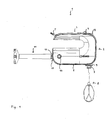
- a hand mixer 1 has according to Fig. 1 a housing 2 with a handle 3, in the rear region of a cylindrical rotary switch 4 is arranged for driving an arranged in the housing 2 electric motor.
- a bend protection 5 is provided for a not shown power cord.
- the handle 3 forms with the remaining part of the housing 2 to the back of the housing open engagement opening for holding the handle 3 with one hand.
- the housing bottom 6 there are two openings 7 through which a stirring tool, for example a pair of whisk 8, can be coupled from the outside to corresponding couplings arranged within the housing 2.
- a stirring tool for example a pair of whisk 8
- To facilitate insertion can protrude a short nozzle 9 on the housing.
- a handle 12 is provided for actuating a closure means for closing the opening 10.
- an actuating element 13 for ejecting the stirring tool and an actuating element 14 for ejecting the mixing tool are arranged on the housing 2.
- the hand mixer 1 corresponds to a Handrmixer invention. To illustrate the invention, the hand mixer 1 in Fig. 1 However, shown in a state in which both the stirring and the mixing tool are used, which is prevented by the inventive design of the hand mixer 1.
- Fig. 2 in a perspective view in which a side wall of the housing 2 is removed, it can be seen, the motor 15 via a worm gear 15 drives two clutches, with only the coupling 17 in Fig. 2 is visible.
- a beater 8 is used for driving by the motor 15; in the invisible coupling another beater is used.
- the beaters 8 are held by the couplings 17.
- an ejector 18 is actuated, which acts on the couplings 17 for releasing and ejecting the Beater 8.
- the ejector 18 can be actuated from an upper side of the housing 2 via an actuating element 12.
- a further clutch 20 is further drivable, which is designed for insertion and holding a mixing tool, which is driven by the motor 15 in the inserted state.
- the further coupling 20 is also associated with an ejection mechanism for releasing and ejecting the mixing tool, which can be actuated via an actuating element 13.
- the hand mixer 1 comprises a control device, not shown, which may in particular comprise operating switches for controlling the rotational speed of the motor 15.
- a closure slide 21 is slidably mounted near the housing bottom 6 in a longitudinal direction of the housing 2.
- the closure slide 21 comprises a lower plate 22 arranged close to the housing bottom, to which two closure flaps 23 bent downwards are formed, of which FIGS Fig. 2 only one is recognizable.
- the shutter 21 is in a rear position in which the flaps 23, the openings 7 in the housing bottom 6, through which the beater 8 can be inserted into the couplings 17, free.
- the closure slide 21 further comprises a bracket 24, which engages around the motor 14 laterally, and an upper plate 25 which carries an eyelet 26 with a slot 27.
- In the slot 27 engages a driver 28, which is held on a displaceable in the longitudinal direction of the housing 2 flexible belt 29.
- the ends of the slot 27 each form stops for the driver.
- the band 29 sets on hinged fasteners 30 at the top of a flap 31, which is arranged to close the opening 10 through which the mixing tool is inserted into the coupling 20.
- the closure flap 31 has a handle 12, via which a user can displace the closure flap 31.
- At the bottom of the flap 31 is an in Fig. 2 symbolically shown coil spring 32, which attaches with its other end to the housing bottom 6 and through which the flap 31 in the in Fig. 2 shown closed position is biased.
- the band 29 is biased, which is guided in its front region via deflection means 33 and is held in the upper region of the housing 2 fixed or longitudinally spring-loaded movable.
- the closure flap 31 is curved according to the shape of the housing 2 in the area concerned. For guiding the closure flap 31 along a curved path, corresponding grooves may be provided on the inside of the housing 2.
- the closure flap 31 may be designed to close the opening 10 substantially tightly, but may also be perforated, for example, in order to allow an air flow for cooling the motor 15.
- two erection aids 34 are arranged in the region of the opening 10, which enable a stable standing position of the hand mixer 1 on a flat surface.
- a mixing tool namely a quick-mix rod 11, used and can be driven by the motor 15 via the corresponding clutch 20.
- the shutter 31 is in an upper position, in which the opening 10 is released by a formed below the handle 12 opening of the shutter 31 for insertion of the mixing tool.
- coil spring 32 extends (in Fig. 3 not shown).
- the band 29 is displaced in its central region, in which the driver 28 is held, in the longitudinal direction of the housing 2 in a front position.
- the flexible band 29 allows the compensation of a change in height of the fastener 30 during the movement of the flap 31.
- the driver 28 which rests against the front stop within the slot 27, is moved over the eyelet 26 of the shutter 21 in a forward position, in the closing flaps 23 close the openings 7 for the stirring tool.
- the slot 27 different lengths of displacement of the shutter slide 21 and the shutter 31 can be compensated.
- the handle 12 is brought into a lower position. In this position, the opening 10 is closed for insertion of a mixing tool and the opening 7 is opened for insertion of the stirring tool. In this state, the beaters 8 can be inserted into the clutches 17 and driven by the motor 15 by operating an operating switch.
- a mixing tool such as a quick-mix rod 11
- the handle 12 from the in Fig. 2 shown lower position in an upper position in which the opening 10 is released and the quick-mix rod 11 can be inserted into the clutch 20.
- the belt 29 is moved to a front position, the driver 28 first reaches the front stop within the slot 27, then moves further forward and takes the shutter slide 21 with.
- the Shutter 21 with the flaps 23 is characterized in the in Fig. 3 shown moved forward position in which the openings 7 are closed. It is therefore not possible to use a stirring tool.
- a simultaneous insertion of a stirring tool and a mixing tool with increased safety can be prevented. Furthermore, inadvertent intervention by a user and / or contamination by the penetration of particles or liquids into an unused opening of the housing can also be avoided.
Landscapes
- Engineering & Computer Science (AREA)
- Mechanical Engineering (AREA)
- Food Science & Technology (AREA)
- Food-Manufacturing Devices (AREA)
Abstract
Description
Die Erfindung betrifft einen Handrührer mit einem Gehäuse, einer Antriebseinrichtung mit einem Motor, einer durch eine erste Öffnung des Gehäuses zugänglichen ersten Kupplungseinrichtung zum Ankuppeln eines Rührwerkzeugs an die Antriebseinrichtung und einer durch eine zweite Öffnung des Gehäuses zugänglichen zweiten Kupplungseinrichtung zum Ankuppeln eines Mixwerkzeugs an die Antriebseinrichtung.The invention relates to a hand-held stirrer having a housing, a drive device with a motor, a first coupling device accessible by a first opening of the housing for coupling a stirring tool to the drive device and a second coupling device accessible by a second opening of the housing for coupling a mixing tool to the drive device ,
Aus
Das Sicherheitselement wirkt derart mit einem Bedienungshebel zusammen, dass zum Betrieb des Mixansatzes der Bedienungshebel vom Benutzer gegen eine Federkraft gehalten werden muss, wobei der Bedienungshebel automatisch in eine Stoppstellung zurückkehrt, wenn das Gerät aus der Hand des Benutzers gleitet. Andererseits hält der Bedienungshebel beim Betrieb des Rühransatzes jede seiner Schaltstellungen, in die er vom Benutzer gebracht worden ist. Das Sicherungselement ist auch geeignet, entweder die Anwesenheit des Mixansatzes oder die Anwesenheit des Rühransatzes anzuzeigen. Eine Fehlbedienung durch gleichzeitiges Einsetzen des Rühr- und des Mixansatzes kann jedoch nicht genügend sicher ausgeschlossen werden. Das Problem einer Verschmutzung der jeweils nicht benutzten Kupplungsvorrichtung durch Eindringen von Partikeln oder Flüssigkeiten wird nicht diskutiert.The security element cooperates with an operating lever such that, for operation of the mix attachment, the operating lever must be held by the user against a spring force, the operating lever automatically returning to a stop position when the device slides out of the user's hand. On the other hand, the operating lever holds during operation of the Stirrup each his switching positions in which he has been brought by the user. The fuse element is also suitable, either indicate the presence of the mix batch or the presence of the stir batch. However, an incorrect operation by simultaneous use of the stirring and Mixansatzes can not be ruled out with sufficient certainty. The problem of contamination of each unused coupling device by penetration of particles or liquids is not discussed.
In
Gemäß
Der Erfindung liegt die Aufgabe zugrunde, einen Handrührer der eingangs genannten Art anzugeben, mit dem die Sicherheit auch für den Fall einer Fehlbedienung erhöht werden kann. Insbesondere soll ein gleichzeitiges Einsetzen eines Rührwerkzeugs und eines Mixwerkzeugs mit einer erhöhten Sicherheit verhindert werden können. Ferner soll möglichst auch ein unabsichtlicher Eingriff eines Benutzers und/oder eine Verschmutzung durch Eindringen von Partikeln oder Flüssigkeiten in die jeweils nicht benutzte Öffnung des Gehäuses vermieden werden können.The invention has for its object to provide a hand mixer of the type mentioned, with which the security can be increased even in the event of incorrect operation. In particular, a simultaneous insertion of a stirring tool and a mixing tool with increased security should be prevented. Furthermore, as far as possible unintentional engagement of a user and / or contamination by the penetration of particles or liquids in the respectively unused opening of the housing can be avoided.
Die Bezugszeichen in sämtlichen Ansprüchen haben keine einschränkende Wirkung, sondern sollen lediglich deren Lesbarkeit verbessern.The reference numbers in all claims have no limiting effect, but are only intended to improve their readability.
Die Lösung der gestellten Aufgabe gelingt durch einen Handrührer mit den Merkmalen des Anspruchs 1.The solution of the problem is achieved by a hand mixer with the features of
Ein erfindungsgemäßer Handrührer weist ein Gehäuse auf, das insbesondere einen Handgriff zum Halten des Handrührers bei der Benutzung durch einen Benutzer umfassen kann und das ansonsten beispielsweise annähernd prismatisch geformt sein kann. Innerhalb des Gehäuses ist eine Antriebseinrichtung aufgenommen, die einen elektrischen Motor und ggf. ein Getriebe umfasst. Die Antriebseinrichtung kann insbesondere eine Mehrzahl von durch den Motor ggf. über das Getriebe antreibbaren Wellen umfassen, die in unterschiedliche Richtungen gerichtete Drehachsen aufweisen können und mit unterschiedlichen Unter- bzw. Übersetzungen mit dem Motor verbunden sein können. Der Handrührer weist ferner eine erste Kupplungseinrichtung zum Ankuppeln eines Rührwerkzeugs an die Antriebseinrichtung auf, wobei die erste Kupplungseinrichtung durch eine erste Öffnung des Gehäuses von außen zugänglich ist, sowie eine zweite Kupplungseinrichtung zum Ankuppeln eines Mixwerkzeugs an die Antriebseinrichtung, wobei die zweite Kupplungseinrichtung durch eine zweite Öffnung des Gehäuses von außen zugänglich ist. Der Handrührer kann ferner Bedienelemente zum Ansteuern des Motors und/oder zum Auswerfen des Rühr- bzw. des Mixwerkzeugs aus der jeweiligen Kupplungseinrichtung aufweisen.A hand-held stirrer according to the invention comprises a housing, which may in particular comprise a handle for holding the hand-held stirrer when in use by a user, and which otherwise may be shaped, for example, approximately prismatically. Within the housing, a drive device is included, which includes an electric motor and possibly a transmission. The drive device may, in particular, comprise a plurality of shafts which can be driven by the motor, possibly via the gear, which may have axes of rotation directed in different directions and may be connected to the motor with different ratios or ratios. The manual agitator furthermore has a first coupling device for coupling a stirring tool to the drive device, wherein the first coupling device is accessible from the outside through a first opening of the housing, and a second coupling device for coupling a mixing tool to the drive device, wherein the second coupling device is provided by a second coupling device Opening of the housing is accessible from the outside. The hand mixer can also controls for driving the motor and / or for ejecting the stirring or the mixing tool from the respective coupling device.
Erfindungsgemäß weist der Handrührer erste und zweite Verschlussmittel zum Verschließen der ersten bzw. der zweiten Öffnung auf, die derart miteinander verbunden sind, dass entweder nur die erste oder nur die zweite Öffnung geöffnet ist. Die ersten und die zweiten Verschlussmittel wirken daher zum wechselweisen Öffnen und Verschließen der ersten oder der zweiten Öffnung zusammen, so dass dann, wenn die erste Öffnung geöffnet ist, die zweite Öffnung verschlossen ist und umgekehrt. Somit ist jeweils nur eine Öffnung geöffnet, so dass zu jedem Zeitpunkt nur in eine Öffnung ein Werkzeug in den Handrührer eingesetzt werden kann.According to the invention, the hand mixer has first and second closure means for closing the first and the second opening, which are connected to one another such that either only the first or only the second opening is opened. The first and second closure means therefore cooperate to alternately open and close the first or second openings so that, when the first opening is opened, the second opening is closed and vice versa. Thus, in each case only one opening is opened, so that at any time only in an opening a tool can be used in the hand mixer.
Hierdurch kann nicht nur besonders sicher verhindert werden, dass gleichzeitig ein Rührwerkzeug und ein Mixwerkzeug in die jeweilige Kupplungseinrichtung des Handrührers eingesetzt und mit der Antriebseinrichtung verbunden werden, sondern es ist auch der Vorteil erreichbar, dass ein versehentlicher Eingriff in die jeweils nicht benutzte Öffnung verhindert wird. Auf diese Weise ist eine besonders hohe Sicherheit gegen Fehlbedienungen erreichbar. Ferner ist der weitere Vorteil erreichbar, dass ein Eindringen von Partikeln, wie etwa Mehlstaub, sowie von Flüssigkeitsspritzern durch die Öffnungen in das Innere des Gehäuses, insbesondere in die Kupplungseinrichtungen, weitgehend vermieden werden kann. Hierdurch kann sowohl die Sicherheit bei der Benutzung des Handrührers als auch die Lebensdauer des Handrührers gesteigert werden.As a result, not only can it be particularly reliably prevented that at the same time a stirring tool and a mixing tool are inserted into the respective coupling device of the hand mixer and connected to the drive device, but it is also achievable the advantage that an accidental interference with the respective unused opening is prevented , In this way, a particularly high level of security against incorrect operation can be achieved. Furthermore, the further advantage can be achieved that penetration of particles, such as flour dust, as well as of liquid splashes through the openings in the interior of the housing, in particular in the coupling devices, can be largely avoided. As a result, both the safety when using the hand mixer and the life of the hand mixer can be increased.
Vorteilhafte Aus- und Weiterbildungen, welche einzeln oder in Kombination miteinander eingesetzt werden können, sind Gegenstand der abhängigen Ansprüche.Advantageous embodiments and developments, which can be used individually or in combination with each other, are the subject of the dependent claims.
Gemäß einer bevorzugten Ausführungsform der Erfindung umfasst das erste Verschlussmittel mindestens eine erste Verschlussklappe zum Verschließen der ersten Öffnung und das zweite Verschlussmittel mindestens eine zweite Verschlussklappe zum Verschließen der zweiten Öffnung. Die Verschlussklappen können jeweils insbesondere starr ausgebildet sein und innerhalb des Gehäuses verschiebbar gehalten sein, bevorzugt entlang der Innenseite einer Außenwand des Gehäuses. Hierdurch ist ein besonders sicheres Verschließen der ersten bzw. der zweiten Öffnung möglich. Insbesondere können die mindestens eine erste bzw. die mindestens eine zweite Verschlussklappe derart stabil ausgebildet sein, dass auch beim versehentlichen Ansetzen des Rühr- bzw. Mixwerkzeugs die jeweilige Öffnung sicher verschlossen bleibt und eine Beschädigung der Verschlussklappe vermieden wird.According to a preferred embodiment of the invention, the first closure means comprises at least one first closure flap for closing the first opening and the second closure means comprises at least one second closure flap for closing the second opening. The closure flaps may each be designed in particular rigidly and be held displaceably within the housing, preferably along the inside of an outer wall of the housing. As a result, a particularly secure closing of the first or the second opening is possible. In particular, the at least one first or the at least one second closure flap can be designed to be stable in such a way that the respective opening remains securely closed even when the mixing or mixing tool is accidentally attached and damage to the closure flap is avoided.
Vorzugsweise sind die mindestens eine erste und die mindestens eine zweite Verschlussklappe über ein auf Zug belastbares flexibles Verbindungsmittel, insbesondere über ein langerstrecktes flexible Verbindungsmittel, besonders bevorzugt über ein flexibles Band, miteinander verbunden. Ein solches flexibles Band kann beispielsweise aus Kunststoff oder aus einem textilen Material bestehen. Es kann aber auch etwa ein Seil oder ein Draht zur Verbindung der mindestens einen ersten mit der mindestens einen zweiten Verschlussklappe dienen. Das flexible Verbindungsmittel ist insbesondere nur auf Zug belastbar und ausreichend flexibel, um bei einer Führung über ein Umlenkmittel eine Umlenkung einer übertragenen Zugkraft zum Zusammenwirken der ersten und zweiten Verschlussmittel zu ermöglichen. Zur Führung des flexiblen Verbindungsmittels können Führungsflächen, Umlenkflächen, Umlenkrollen oder andere Führungs- und Umlenkmittel vorgesehen sein.Preferably, the at least one first and the at least one second closure flap are connected to one another via a flexible connecting means that can be loaded with tension, in particular via an elongated flexible connecting means, particularly preferably via a flexible band. Such a flexible band may for example consist of plastic or of a textile material. But it can also serve as a rope or a wire for connecting the at least one first with the at least one second flap. In particular, the flexible connecting means can only be subjected to tensile load and be sufficiently flexible to permit a deflection of a transmitted tensile force for the interaction of the first and second closure means in the case of a guide via a deflecting means. To guide the flexible connecting means guide surfaces, deflection surfaces, pulleys or other guiding and deflecting means may be provided.
Dadurch, dass die mindestens eine erste und die mindestens eine zweite Verschlussklappe über ein flexibles Verbindungsmittel miteinander verbunden sind, ist ein größtmögliches Maß an konstruktiver Gestaltungsfreiheit in der Anordnung und Ausbildung der Öffnungen zum Einsetzen des Rühr- bzw. des Mixwerkzeugs erreichbar. Insbesondere kann eine unter ergonomischen und unter Sicherheitsgesichtspunkten optimale Gestaltung, etwa eine versetzte oder winklige Anordnung, gewählt werden und auch bei einer solchen Anordnung ein Zusammenwirken der ersten und zweiten Verschlussmittel zum wechselseitigen Verschließen der ersten oder der zweiten Öffnung ermöglicht werden.Due to the fact that the at least one first and the at least one second closure flap are connected to one another via a flexible connection means, the greatest possible degree of constructional freedom in the arrangement and design of the openings for inserting the stirring or mixing tool is achievable. In particular, an ergonomic and safety-optimal design, such as a staggered or angled arrangement can be selected and also in such an arrangement, a cooperation of the first and second closure means for mutual closing of the first or the second opening are made possible.
In bevorzugter Weise ist das flexible Verbindungsmittel vorgespannt. Die Vorspannung kann durch eine Federkraft einer an dem flexiblen Verbindungsmittel angreifenden Feder, insbesondere einer Schraubenfeder, erzeugt werden. Es kann aber auch das flexible Verbindungsmittel selbst elastisch ausgebildet sein und unter Vorspannung im Handrührgerät eingebaut sein.Preferably, the flexible connection means is biased. The bias voltage can be generated by a spring force of an acting on the flexible connecting means spring, in particular a coil spring. But it can also be the flexible one Connecting means itself be designed to be elastic and installed under bias in the hand mixer.
Dadurch, dass das flexible Verbindungsmittel unter Vorspannung steht, können auf einfache Weise Bewegungen der Verschlussklappen in beide Richtungen übertragen werden. Auf diese Weise ist ein besonders einfacher und betriebssicherer Aufbau erreichbar.The fact that the flexible connecting means is biased, movements of the flaps can be transmitted in both directions in a simple manner. In this way, a particularly simple and reliable construction can be achieved.
Gemäß einer bevorzugten Ausführungsform der Erfindung ist mindestens eine der Verschlussklappen durch eine Feder vorgespannt. Insbesondere kann die Feder direkt an der Verschlussklappe angreifen, wobei das flexible Verbindungsmittel an einem dem Angriffspunkt der Feder gegenüberliegenden Punkt der Verschlussklappe an dieser angreift. Das flexible Verbindungsmittel kann beispielsweise dadurch an der Verschlussklappe angreifen, dass es mit einer Kleb-, Schraub- oder Nietverbindung daran befestigt ist oder auch etwa durch eine Öse der Verschlussklappe hindurch gezogen ist. Insbesondere kann die Feder an der zweiten Verschlussklappe, die zum Verschließen derjenigen Öffnung des Gehäuses vorgesehen ist, durch die der Mixansatz in die zweite Kupplungseinrichtung einsetzbar ist, angreifen. Hierdurch ist ein weiter vereinfachter konstruktiver Aufbau erreichbar.According to a preferred embodiment of the invention, at least one of the shutters is biased by a spring. In particular, the spring can act directly on the closure flap, wherein the flexible connecting means engages at a point opposite to the point of engagement of the spring of the closure flap. The flexible connection means can for example attack the closure flap by being attached thereto with an adhesive, screw or rivet connection or else pulled about through an eyelet of the closure flap. In particular, the spring on the second closure flap, which is provided for closing that opening of the housing through which the Mixansatz can be inserted into the second coupling device, attack. As a result, a further simplified structural design can be achieved.
Vorzugsweise ist die Verschlussklappe in eine Schließstellung vorgespannt. Sollte beispielsweise das flexible Verbindungsmittel reißen oder von einem Führungsmittel abgleiten, so wird die Verschlussklappe in eine Schließstellung gebracht. Hierdurch ist bei einem einfachen Aufbau eine weiter erhöhte Sicherheit erreichbar. Ein besonderer Sicherheitsgewinn ist dabei erreichbar, wenn die Verschlussklappe, die in Schließstellung vorgespannt ist, die zweite Verschlussklappe ist, da der Mixansatz üblicherweise mit einer besonders hohen Drehzahl betrieben wird und ein unabsichtlicher Eingriff in die zweite Kupplungseinrichtung daher mit einem besonders hohen Verletzungsrisiko verbunden wäre.Preferably, the closure flap is biased in a closed position. For example, if the flexible connecting means tear or slide off a guide means, the closure flap is brought into a closed position. As a result, a further increased security can be achieved with a simple structure. A particular gain in security is achievable when the closure flap, which is biased in the closed position, the second flap, since the Mixansatz is usually operated at a particularly high speed and unintentional intervention in the second coupling device would therefore be associated with a particularly high risk of injury.
Gemäß einer bevorzugten Ausführungsform der Erfindung ist die mindestens eine erste Verschlussklappe als Teil eines Verschlussschiebers ausgebildet, der innerhalb des Gehäuses verschiebbar ist. Der Verschlussschieber weist in vorteilhafter Weise eine Öse auf, in die ein Mitnehmer des flexiblen Verbindungsmittels eingreift. Die mindestens eine erste Verschlussklappe kann einstückig mit dem Verschlussschieber ausgebildet sein oder mit diesem durch Klebung, Verschraubung, Vernietung oder in einer anderen Weise verbunden sein. Der Mitnehmer kann mit dem flexiblen Verbindungsmittel, insbesondere mit einem flexiblen Band, durch Kleben, Klemmen, Schrauben, Nieten oder auf eine andere Weise verbunden sein. Das flexible Verbindungsmittel kann insbesondere mit einem ersten Ende an der zweiten Verschlussklappe angreifen, mit einem zweiten Ende innerhalb des Gehäuses beweglich gehalten oder, sofern das flexible Verbindungsmittel selbst elastisch ausgebildet ist, innerhalb des Gehäuses befestigt sein, und in einem mittleren Bereich den Mitnehmer tragen. Hierdurch wird auf konstruktiv besonders einfache Weise ein Zusammenwirken der mindestens einen ersten Verschlussklappe mit der mindestens einen zweiten Verschlussklappe ermöglicht.According to a preferred embodiment of the invention, the at least one first closure flap is formed as part of a closure slide, which is displaceable within the housing. The closure slide advantageously has an eyelet, in which engages a driver of the flexible connection means. The at least one first closure flap may be formed integrally with the closure slide or connected thereto by gluing, screwing, riveting or in some other way. The driver may be connected to the flexible connection means, in particular to a flexible band, by gluing, clamping, screwing, riveting or otherwise. In particular, the flexible connecting means may engage with a first end on the second closure flap, be movably supported with a second end within the enclosure, or, if the flexible connection means itself is resilient, secured within the enclosure and support the entrainment means in a central region. As a result, cooperation of the at least one first closure flap with the at least one second closure flap is made possible in a structurally particularly simple manner.
Vorzugsweise bildet die Öse ein sich in Verschieberichtung des Verschlussschiebers erstreckendes Langloch aus, innerhalb dessen der Mitnehmer über eine durch zwei Anschläge begrenzte Strecke beweglich ist. Insbesondere ist der Mitnehmer in dem Langloch geführt, wobei das Langloch eine Länge aufweist, die länger ist als die entsprechende Länge des Mitnehmers. Der Mitnehmer kann somit innerhalb des Langlochs je nach Verschieberichtung des Bands unterschiedliche Positionen zwischen den zwei Anschlägen einnehmen. Aufgrund der Reibung des Verschlussschiebers bei dessen Bewegung innerhalb des Gehäuses wird der Verschlussschieber insbesondere erst dann vom Mitnehmer mitgenommen, wenn der Mitnehmer bei einer Bewegung des flexiblen Verbindungsmittels einen Anschlag erreicht hat.Preferably, the eyelet forms an elongated hole extending in the direction of displacement of the closure slide, within which the driver is movable over a distance limited by two stops. In particular, the driver is guided in the slot, wherein the slot has a length which is longer than the corresponding length of the driver. The driver can thus occupy different positions between the two attacks within the slot depending on the direction of the tape. Due to the friction of the closure slide during its movement within the housing, the closure slide is only taken in particular by the driver when the driver has reached a stop during a movement of the flexible connecting means.
Hierdurch ist der weitere Vorteil erreichbar, dass eine derartige Verbindung der mindestens einen ersten Verschlussklappe und der mindestens einen zweiten Verschlussklappe miteinander erreicht werden kann, bei der die mindestens eine erste und die mindestens eine zweite Verschlussklappe unterschiedlich lange Verschiebewege aufweisen. Dies kann beispielsweise dann vorteilhaft sein, wenn die erste Öffnung eine andere Größe aufweist als die zweite Öffnung. So kann etwa die zweite Öffnung, die zum Durchführen eines Mixwerkzeugs ausgebildet ist, kreisförmig mit einem größeren Durchmesser ausgebildet sein, während die erste Öffnung zum Durchführen eines Rührwerkzeugs mit einem kleineren Durchmesser ausgebildet sein kann. Zum Verschließen der ersten Öffnung ist in diesem Fall ein geringerer Verschiebeweg der Verschlussklappe notwendig als zum Verschließen der zweiten Öffnung. In einem geringeren Maße können unterschiedlich lange Verschiebewege bei Verwendung eines elastischen Verbindungsmittels beispielsweise auch dadurch ausgeglichen werden, dass am Anbringungsort des Mitnehmers die Längung des Verbindungsmittels geringer sein kann als am ersten Ende des Verbindungsmittels, mit dem dieses an der mindestens einen zweiten Verschlussklappe ansetzt.As a result, the further advantage can be achieved that such a connection of the at least one first closing flap and the at least one second closing flap can be achieved, in which the at least one first and the at least one second closing flap have different lengths of displacement. This can be advantageous, for example, if the first opening has a different size than the second opening. For example, the second opening, which is designed to carry out a mixing tool, may be formed in a circle with a larger diameter, while the first opening may be designed to pass through a stirring tool with a smaller diameter. For closing the first opening, a smaller displacement path of the closure flap is necessary in this case than for closing the second opening. In one smaller dimensions can be compensated for different lengths of displacement paths when using an elastic connecting means, for example, that at the mounting location of the driver, the elongation of the connecting means may be less than at the first end of the connecting means with which this attaches to the at least one second flap.
Gemäß einer bevorzugten Ausführungsform wirkt das flexible Verbindungsmittel mit einem Steuerungselement zum Ansteuern des Motors zusammen. So kann beispielsweise eine unterschiedliche Ansteuerung des Motors hinsichtlich der Leistung und/oder hinsichtlich verfügbarer Schaltstufen vorgesehen sein, je nachdem, ob ein Rühr - oder ein Mixwerkzeug einsetzbar bzw. eingesetzt ist. Das flexible Verbindungsmittel kann beispielsweise mit einem ersten Ende an der zweiten Verschlussklappe ansetzen und mit einem zweiten Ende innerhalb einer Steuerungseinheit gehalten sein, wobei ein Steuerungselement je nach Position bzw. Spannung des flexiblen Verbindungsmittels unterschiedliche Betriebs- oder Bedienungsweisen ermöglichen kann. Hierdurch ist eine besonders einfache Bedienung bei einer möglichst vielseitigen Verwendbarkeit des Handrührers erreichbar.According to a preferred embodiment, the flexible connection means cooperates with a control element for driving the motor. Thus, for example, a different control of the motor with regard to the power and / or with regard to available switching stages can be provided, depending on whether a stirring or a mixing tool can be used or used. The flexible connection means may for example be attached to the second closure flap with a first end and be held with a second end within a control unit, wherein a control element may enable different operating or operating modes depending on the position or tension of the flexible connection means. As a result, a particularly simple operation with as versatile as possible usability of the hand mixer can be achieved.
Weiterhin ist es bevorzugt, dass die mindestens eine erste oder die mindestens eine zweite Verschlussklappe mit einer Handhabe zum Betätigen der ersten und der zweiten Verschlussmittel versehen ist. Hierdurch wird eine besonders einfache Bedienung ermöglicht, insbesondere ist aufgrund des Zusammenwirkens der Verschlussmittel zum abwechselnden Verschließen der ersten oder der zweiten Öffnung durch Betätigung der Handhabe eine Betätigung beider Verschlussmittel möglich. Es können auch sowohl mindestens eine erste als auch mindestens eine zweite Verschlussklappe jeweils eine solche Handhabe aufweisen. Dies ermöglicht es dem Benutzer, eine beliebige der Handhaben zu wählen, wodurch die Bedienung weiter vereinfacht wird.Furthermore, it is preferred that the at least one first or the at least one second closure flap is provided with a handle for actuating the first and the second closure means. In this way, a particularly simple operation is possible, in particular an actuation of both closure means is possible due to the interaction of the closure means for alternately closing the first or the second opening by actuating the handle. Both at least one first and at least one second closure flap may each have such a handle. This allows the user to select any of the handles, further simplifying operation.
Gemäß einer bevorzugten Ausführungsform der Erfindung definieren die erste und die zweite Öffnung näherungsweise eine erste und eine zweite Öffnungsebene, die nicht miteinander zusammenfallen, d.h. nicht in einer Ebene angeordnet sind, und insbesondere auch nicht parallel zueinander liegen. Durch die erste und die zweite Kupplungseinrichtung werden ferner eine erste und eine zweite Kupplungsrichtung zum Einsetzen der jeweiligen Werkzeuge in die betreffende Kupplungseinrichtung, die im Wesentlichen senkrecht zur jeweiligen Öffnungsebene stehen, definiert. Die erste und die zweite Kupplungsrichtung sind somit insbesondere nicht parallel zueinander gerichtet. Hierdurch wird die Handhabung die Handrührers erleichtert, da ein Rühr- und ein Mixwerkzeug in der Regel unterschiedliche Längen aufweisen, bei der Benutzung unterschiedlich gehalten werden und daher eine unterschiedliche Ausrichtung des Handgriffs des Handrührers zum jeweiligen Werkzeug vorteilhaft ist.According to a preferred embodiment of the invention, the first and the second opening define approximately a first and a second opening plane, which do not coincide with each other, ie are not arranged in a plane, and in particular also not parallel to each other. By the first and the second coupling means are further a first and a second coupling direction for insertion of the respective tools in the respective coupling device, which in Substantially perpendicular to the respective opening plane defined. The first and the second coupling direction are therefore in particular not directed parallel to one another. As a result, the handling of the hand mixer is facilitated, since a stirring and a mixing tool usually have different lengths, are held differently in use and therefore a different orientation of the handle of the hand mixer for each tool is advantageous.
Das Gehäuse kann im Bereich der Öffnungen eine gekrümmte Oberfläche aufweisen, so dass die erste und/oder die zweite Öffnung nicht exakt eine Ebene definieren. Dies kann etwa aus Sicherheits- oder Handhabungsgründen vorteilhaft sein. In diesem Fall kann die mindestens eine erste und/oder die mindestens eine zweite Verschlussklappe gekrümmt ausgebildet sein und entlang einer gekrümmten Bahn innerhalb des Gehäuses verschiebbar sein.The housing may have a curved surface in the region of the openings, so that the first and / or the second opening do not exactly define a plane. This can be advantageous for safety or handling reasons. In this case, the at least one first and / or the at least one second closure flap can be curved and can be displaced along a curved path within the housing.
Bevorzugt können die erste und die zweite Öffnungsebene näherungsweise senkrecht aufeinander stehen; auch die Kupplungsrichtungen stehen dann näherungsweise senkrecht aufeinander. In vorteilhafter Weise sind die erste und die zweite Öffnung an unterschiedlichen Seiten des Gehäuses angeordnet. So kann beispielsweise bei einem aus Fertigungs- und Ergonomiegründen näherungsweise prismatisch oder quaderförmig ausgebildeten Gehäuse das Rührwerkzeug von einer Unterseite einsetzbar sein, während das Mixwerkzeug von einer Rückseite einsetzbar ist. Hierdurch wird die Handhabung des Handrührers zur abwechselnden Benutzung eines Rühr- oder eines Mixwerkzeugs weiter erleichtert. Ferner ist hierdurch eine besonders einfache konstruktive Ausführung erreichbar.Preferably, the first and the second opening plane may be approximately perpendicular to each other; Also, the coupling directions are then approximately perpendicular to each other. Advantageously, the first and second openings are arranged on different sides of the housing. For example, in the case of an approximately prismatic or cuboid-shaped housing for production and ergonomic reasons, the stirring tool can be used from a lower side, while the mixing tool can be inserted from a rear side. As a result, the handling of the hand mixer for the alternate use of a stirring or a mixing tool is further facilitated. Furthermore, this is a particularly simple structural design achievable.
Vorzugsweise umfasst das Rühr- und/oder das Mixwerkzeug, insbesondere das Rührwerkzeug, mehrere zusammenwirkende Teilwerkzeuge. Die jeweilige Kupplungseinrichtung umfasst in diesem Falle mehrere Kupplungen für die jeweiligen Teilwerkzeuge. Beispielsweise kann das erste Werkzeug als ein Paar von Rührbesen oder Knethaken ausgebildet sein, während das Mixwerkzeug als Stabmixansatz ausgebildet sein kann. Hierdurch kann eine besonders vielseitige Verwendbarkeit des Handrührers erreicht werden.Preferably, the stirring and / or the mixing tool, in particular the stirring tool, comprises a plurality of cooperating sub-tools. The respective coupling device comprises in this case a plurality of couplings for the respective part tools. For example, the first tool may be formed as a pair of whisk or dough hook, while the mixing tool may be formed as a stick mix approach. As a result, a particularly versatile usability of the hand mixer can be achieved.
In bevorzugter Weise umfasst die erste und/oder die zweite Öffnung, insbesondere die erste Öffnung, mehrere Teilöffnungen. Die ersten und/oder die zweiten Verschlussmittel können dementsprechend eine Mehrzahl von Verschlussklappen aufweisen. Hierdurch ist eine besonders einfache konstruktive Ausgestaltung zum Antreiben von Rührwerkzeugen, die mehrere miteinander zusammenwirkende Teilwerkzeuge umfassen, erreichbar.Preferably, the first and / or the second opening, in particular the first opening, comprises a plurality of partial openings. The first and / or the second closure means may accordingly have a plurality of closure flaps. As a result, a particularly simple structural design for driving agitating tools comprising a plurality of cooperating sub-tools, accessible.
Weitere vorteilhafte Ausgestaltungen werden nachfolgend an Hand eines in den Zeichnungen dargestellten Ausführungsbeispiels, auf welches die Erfindung jedoch nicht beschränkt ist, näher beschrieben.Further advantageous embodiments will be described in more detail below with reference to an embodiment shown in the drawings, to which the invention is not limited.
Es zeigen schematisch:
-
Fig. 1 einen Handrührer in einer Seitenansicht; -
Fig. 2 ein Ausführungsbeispiel eines erfindungsgemäßen Handrührers in einer geöffneten perspektivischen Ansicht mit eingesetztem Rührwerkzeug; -
Fig. 3 das Ausführungsbeispiel des erfindungsgemäßen Handrührers in einer geöffneten perspektivischen Ansicht mit eingesetztem Mixwerkzeug.
-
Fig. 1 a hand mixer in a side view; -
Fig. 2 an embodiment of a hand mixer according to the invention in an open perspective view with inserted stirring tool; -
Fig. 3 the embodiment of the hand mixer according to the invention in an open perspective view with inserted mixing tool.
Bei der nachfolgenden Beschreibung eines Handrührers sowie einer bevorzugten Ausführungsform der vorliegenden Erfindung bezeichnen gleiche Bezugszeichen gleiche oder vergleichbare Komponenten. Der Übersichtlichkeit halber sind nicht in allen Figuren alle Bezugszeichen eingetragen.In the following description of a hand mixer and a preferred embodiment of the present invention, like reference characters designate like or similar components. For the sake of clarity, not all figures are entered in all figures.
Ein Handrührer 1 weist gemäß
Wie in
Wie in
Das Band 29 setzt über gelenkig ausgebildete Befestigungsmittel 30 am oberen Rand einer Verschlussklappe 31 an, die zum Verschließen der Öffnung 10, durch die das Mixwerkzeug in die Kupplung 20 einsetzbar ist, angeordnet ist. Die Verschlussklappe 31 weist eine Handhabe 12 auf, über die ein Benutzer die Verschlussklappe 31 verschieben kann. Am unteren Rand der Verschlussklappe 31 setzt eine in
Die Verschlussklappe 31 ist entsprechend der Form des Gehäuses 2 im betreffenden Bereich gekrümmt ausgebildet. Zur Führung der Verschlussklappe 31 entlang einer gekrümmten Bahn können entsprechende Nuten auf der Innenseite des Gehäuses 2 vorgesehen sein. Die Verschlussklappe 31 kann ausgebildet sein, um die Öffnung 10 weitgehend dicht zu verschließen, kann aber auch beispielsweise perforiert ausgebildet sein, um einen Luftzustrom zur Kühlung des Motors 15 zu ermöglichen. An der Rückseite des Gehäuses 2 sind im Bereich der Öffnung 10 zwei Aufstellhilfen 34 angeordnet, die auf einer ebenen Fläche eine stabile Standposition des Handrührers 1 ermöglichen.The
In
Zur Benutzung des Handrührers 1 mit einem Rührwerkzeug, beispielsweise den Rührbesen 8, wird die Handhabe 12 in eine untere Position gebracht. In dieser Position ist die Öffnung 10 zum Einsetzen eines Mixwerkzeugs verschlossen und die Öffnung 7 zum Einsetzen des Rührwerkzeugs geöffnet. In diesem Zustand können die Rührbesen 8 in die Kupplungen 17 eingesetzt und durch Betätigung eines Betriebsschalters vom Motor 15 angetrieben werden.To use the
Soll nun ein Mixwerkzeug, beispielsweise ein Schnellmixstab 11, angesetzt werden, so sind zunächst die Rührbesen 8 durch Betätigung des Auswerfers 18 auszuwerfen. Sodann ist die Handhabe 12 aus der in
Soll wieder mit einem Rührwerkzeug gearbeitet werden, so ist durch Betätigung des Auswerfers 21 der Schnellmixstab 11 vom Handrührer 1 zu lösen und die Handhabe 12 in die untere Position zu bringen. Hierdurch wird das Band 29 nach hinten verschoben, der Mitnehmer gelangt zunächst an seinen hinteren Anschlag innerhalb des Langlochs 27 und bewegt sich dann noch weiter nach hinten, so dass der Verschlussschieber 21 in seine in
Bei dem erfindungsgemäßen Handrührer kann ein gleichzeitiges Einsetzen eines Rührwerkzeugs und eines Mixwerkzeugs mit einer erhöhten Sicherheit verhindert werden. Ferner kann auch ein unabsichtlicher Eingriff eines Benutzers und/oder eine Verschmutzung durch Eindringen von Partikeln oder Flüssigkeiten in eine nicht benutzte Öffnung des Gehäuses vermieden werden.In the hand mixer according to the invention, a simultaneous insertion of a stirring tool and a mixing tool with increased safety can be prevented. Furthermore, inadvertent intervention by a user and / or contamination by the penetration of particles or liquids into an unused opening of the housing can also be avoided.
Die in der vorstehenden Beschreibung, den Ansprüchen und den Zeichnungen offenbarten Merkmale können sowohl einzeln als auch in beliebiger Kombination für die Verwirklichung der Erfindung in ihren verschiedenen Ausgestaltungen von Bedeutung sein.The features disclosed in the foregoing description, the claims and the drawings may be of importance both individually and in any combination for the realization of the invention in its various forms.
- 11
- HandrührerHandrührer
- 22
- Gehäusecasing
- 33
- Handgriffhandle
- 44
- Drehschalterrotary switch
- 55
- Knickschutzkink protection
- 66
- Gehäusebodencaseback
- 77
- Öffnungopening
- 88th
- Rührbesenwhisk
- 99
- StutzenSupport
- 1010
- Öffnungopening
- 1111
- Schnellmixstabquick blender
- 1212
- Handhabehandle
- 1313
- Betätigungselementactuator
- 1414
- Betätigungselementactuator
- 1515
- Motorengine
- 1616
- Schneckengetriebeworm gear
- 1717
- Kupplungclutch
- 1818
- Auswerferejector
- 1919
- Flügelradimpeller
- 2020
- Kupplungclutch
- 2121
- Verschlussschieberclosing slide
- 2222
- Untere PlatteLower plate
- 2323
- Verschlussklappeflap
- 2424
- Bügelhanger
- 2525
- Obere PlatteUpper plate
- 2626
- Öseeyelet
- 2727
- LanglochLong hole
- 2828
- Mitnehmertakeaway
- 2929
- Bandtape
- 3030
- Befestigungsmittelfastener
- 3131
- Verschlussklappeflap
- 3232
- Schraubenfedercoil spring
- 3333
- Umlenkmitteldeflecting
- 3434
- AufstellhilfeErecting
Claims (15)
Priority Applications (2)
| Application Number | Priority Date | Filing Date | Title |
|---|---|---|---|
| SI201230083T SI2550906T1 (en) | 2011-07-29 | 2012-07-19 | Hand mixer |
| PL12177001T PL2550906T3 (en) | 2011-07-29 | 2012-07-19 | Hand mixer |
Applications Claiming Priority (1)
| Application Number | Priority Date | Filing Date | Title |
|---|---|---|---|
| DE102011080133A DE102011080133A1 (en) | 2011-07-29 | 2011-07-29 | Handrührer |
Publications (2)
| Publication Number | Publication Date |
|---|---|
| EP2550906A1 true EP2550906A1 (en) | 2013-01-30 |
| EP2550906B1 EP2550906B1 (en) | 2014-07-09 |
Family
ID=46614297
Family Applications (1)
| Application Number | Title | Priority Date | Filing Date |
|---|---|---|---|
| EP12177001.0A Active EP2550906B1 (en) | 2011-07-29 | 2012-07-19 | Hand mixer |
Country Status (4)
| Country | Link |
|---|---|
| EP (1) | EP2550906B1 (en) |
| DE (1) | DE102011080133A1 (en) |
| PL (1) | PL2550906T3 (en) |
| SI (1) | SI2550906T1 (en) |
Cited By (1)
| Publication number | Priority date | Publication date | Assignee | Title |
|---|---|---|---|---|
| CN112403362A (en) * | 2019-08-20 | 2021-02-26 | 深圳市联创三金电器有限公司 | Fast-assembling quick-fetching mechanism and handheld stirring device with same |
Families Citing this family (1)
| Publication number | Priority date | Publication date | Assignee | Title |
|---|---|---|---|---|
| DE102017223672B4 (en) * | 2017-12-22 | 2021-08-12 | BSH Hausgeräte GmbH | Electromotive kitchen appliance with proppant |
Citations (4)
| Publication number | Priority date | Publication date | Assignee | Title |
|---|---|---|---|---|
| DE69600634T2 (en) | 1995-02-16 | 1999-03-18 | Moulinex Sa | ELECTRICALLY OPERATED HANDBAGS AND STIRRERS |
| DE60004240T2 (en) * | 1999-07-05 | 2004-04-15 | Seb S.A. | ELECTRICALLY POWERED HAND RACK AND STIRRER |
| DE60006695T2 (en) | 1999-09-16 | 2004-09-23 | Seb S.A. | ELECTRICALLY OPERATED STIRRING AND MIXING UNIT |
| EP1191870B1 (en) | 1999-06-17 | 2006-11-08 | Seb S.A. | Electric hand-operated rotary beater/mixer comprising a safety device |
-
2011
- 2011-07-29 DE DE102011080133A patent/DE102011080133A1/en not_active Ceased
-
2012
- 2012-07-19 PL PL12177001T patent/PL2550906T3/en unknown
- 2012-07-19 EP EP12177001.0A patent/EP2550906B1/en active Active
- 2012-07-19 SI SI201230083T patent/SI2550906T1/en unknown
Patent Citations (4)
| Publication number | Priority date | Publication date | Assignee | Title |
|---|---|---|---|---|
| DE69600634T2 (en) | 1995-02-16 | 1999-03-18 | Moulinex Sa | ELECTRICALLY OPERATED HANDBAGS AND STIRRERS |
| EP1191870B1 (en) | 1999-06-17 | 2006-11-08 | Seb S.A. | Electric hand-operated rotary beater/mixer comprising a safety device |
| DE60004240T2 (en) * | 1999-07-05 | 2004-04-15 | Seb S.A. | ELECTRICALLY POWERED HAND RACK AND STIRRER |
| DE60006695T2 (en) | 1999-09-16 | 2004-09-23 | Seb S.A. | ELECTRICALLY OPERATED STIRRING AND MIXING UNIT |
Cited By (1)
| Publication number | Priority date | Publication date | Assignee | Title |
|---|---|---|---|---|
| CN112403362A (en) * | 2019-08-20 | 2021-02-26 | 深圳市联创三金电器有限公司 | Fast-assembling quick-fetching mechanism and handheld stirring device with same |
Also Published As
| Publication number | Publication date |
|---|---|
| SI2550906T1 (en) | 2014-11-28 |
| PL2550906T3 (en) | 2014-12-31 |
| EP2550906B1 (en) | 2014-07-09 |
| DE102011080133A1 (en) | 2013-01-31 |
Similar Documents
| Publication | Publication Date | Title |
|---|---|---|
| DE3490450C2 (en) | Instrument for inserting surgical fasteners | |
| DE19508035C2 (en) | Power tool with removable additional handle | |
| EP2755804B1 (en) | Motor operated machine tool | |
| EP2429768B1 (en) | Setting tool | |
| DE202008005129U1 (en) | Vehicle door lock with mounting plate | |
| EP1800580B1 (en) | Handheld mixer switchable between short and long operation depending on the attached tool | |
| EP2746703B1 (en) | Door for a domestic refrigeration device with a handle that can be slid without dismantling and domestic refrigerator and method for positioning a handle | |
| DE202020107104U1 (en) | Furniture drive | |
| EP2550906B1 (en) | Hand mixer | |
| EP2732877B1 (en) | Piston stroke pipette with exchangeable displacer unit | |
| DE1529273C3 (en) | Multipurpose electric kitchen appliance | |
| EP2550905B1 (en) | Mélangeur manuel | |
| DE60004240T2 (en) | ELECTRICALLY POWERED HAND RACK AND STIRRER | |
| DE2802155A1 (en) | Hand held electric kitchen mixer - has gear frame with guide ducts for two drive carriages | |
| EP3623561B1 (en) | Driving carriage for a gate as well as a gate drive | |
| DE102007063076A1 (en) | Key for execution of closing process of doors, has blade that is introduced into lock and is coordinated on lock, where blade is connected with mechanism that executes closing process | |
| EP1884156B1 (en) | Hand-operated electrical machine tool and coupler for a hand-operated electrical machine tool | |
| EP0074486A1 (en) | Slide plate ventilation with a fan driven by a motor | |
| DE10234316B4 (en) | Mixing device with an electric drive motor and safety device | |
| EP3531871B1 (en) | Piece of furniture and method for opening a drawer and an inner drawer | |
| DE3527313A1 (en) | ELECTRICALLY POWERED HAIR DRYER | |
| DE102006030222B4 (en) | Hand stirrer with safety lock | |
| DE19607765A1 (en) | Security lock for a door | |
| EP1717067A1 (en) | Drive for a trailer coupling | |
| DE102008003419A1 (en) | Punching tool for use with punching tool plate for punching unit of punching and binding device, is made of flat oblong material piece and has cutting edge at front side and shaft running in longitudinal direction of punching tool |
Legal Events
| Date | Code | Title | Description |
|---|---|---|---|
| PUAI | Public reference made under article 153(3) epc to a published international application that has entered the european phase |
Free format text: ORIGINAL CODE: 0009012 |
|
| AK | Designated contracting states |
Kind code of ref document: A1 Designated state(s): AL AT BE BG CH CY CZ DE DK EE ES FI FR GB GR HR HU IE IS IT LI LT LU LV MC MK MT NL NO PL PT RO RS SE SI SK SM TR |
|
| AX | Request for extension of the european patent |
Extension state: BA ME |
|
| 17P | Request for examination filed |
Effective date: 20130730 |
|
| RBV | Designated contracting states (corrected) |
Designated state(s): AL AT BE BG CH CY CZ DE DK EE ES FI FR GB GR HR HU IE IS IT LI LT LU LV MC MK MT NL NO PL PT RO RS SE SI SK SM TR |
|
| RIC1 | Information provided on ipc code assigned before grant |
Ipc: A47J 43/08 20060101ALI20130814BHEP Ipc: A47J 43/07 20060101AFI20130814BHEP |
|
| GRAP | Despatch of communication of intention to grant a patent |
Free format text: ORIGINAL CODE: EPIDOSNIGR1 |
|
| INTG | Intention to grant announced |
Effective date: 20140217 |
|
| GRAS | Grant fee paid |
Free format text: ORIGINAL CODE: EPIDOSNIGR3 |
|
| GRAA | (expected) grant |
Free format text: ORIGINAL CODE: 0009210 |
|
| AK | Designated contracting states |
Kind code of ref document: B1 Designated state(s): AL AT BE BG CH CY CZ DE DK EE ES FI FR GB GR HR HU IE IS IT LI LT LU LV MC MK MT NL NO PL PT RO RS SE SI SK SM TR |
|
| REG | Reference to a national code |
Ref country code: GB Ref legal event code: FG4D Free format text: NOT ENGLISH |
|
| REG | Reference to a national code |
Ref country code: CH Ref legal event code: EP Ref country code: AT Ref legal event code: REF Ref document number: 676252 Country of ref document: AT Kind code of ref document: T Effective date: 20140715 |
|
| REG | Reference to a national code |
Ref country code: IE Ref legal event code: FG4D Free format text: LANGUAGE OF EP DOCUMENT: GERMAN |
|
| REG | Reference to a national code |
Ref country code: DE Ref legal event code: R096 Ref document number: 502012000972 Country of ref document: DE Effective date: 20140821 |
|
| REG | Reference to a national code |
Ref country code: NL Ref legal event code: VDEP Effective date: 20140709 |
|
| REG | Reference to a national code |
Ref country code: LT Ref legal event code: MG4D |
|
| REG | Reference to a national code |
Ref country code: PL Ref legal event code: T3 |
|
| PG25 | Lapsed in a contracting state [announced via postgrant information from national office to epo] |
Ref country code: FI Free format text: LAPSE BECAUSE OF FAILURE TO SUBMIT A TRANSLATION OF THE DESCRIPTION OR TO PAY THE FEE WITHIN THE PRESCRIBED TIME-LIMIT Effective date: 20140709 Ref country code: LT Free format text: LAPSE BECAUSE OF FAILURE TO SUBMIT A TRANSLATION OF THE DESCRIPTION OR TO PAY THE FEE WITHIN THE PRESCRIBED TIME-LIMIT Effective date: 20140709 Ref country code: NO Free format text: LAPSE BECAUSE OF FAILURE TO SUBMIT A TRANSLATION OF THE DESCRIPTION OR TO PAY THE FEE WITHIN THE PRESCRIBED TIME-LIMIT Effective date: 20141009 Ref country code: ES Free format text: LAPSE BECAUSE OF FAILURE TO SUBMIT A TRANSLATION OF THE DESCRIPTION OR TO PAY THE FEE WITHIN THE PRESCRIBED TIME-LIMIT Effective date: 20140709 Ref country code: GR Free format text: LAPSE BECAUSE OF FAILURE TO SUBMIT A TRANSLATION OF THE DESCRIPTION OR TO PAY THE FEE WITHIN THE PRESCRIBED TIME-LIMIT Effective date: 20141010 Ref country code: SE Free format text: LAPSE BECAUSE OF FAILURE TO SUBMIT A TRANSLATION OF THE DESCRIPTION OR TO PAY THE FEE WITHIN THE PRESCRIBED TIME-LIMIT Effective date: 20140709 Ref country code: PT Free format text: LAPSE BECAUSE OF FAILURE TO SUBMIT A TRANSLATION OF THE DESCRIPTION OR TO PAY THE FEE WITHIN THE PRESCRIBED TIME-LIMIT Effective date: 20141110 Ref country code: BG Free format text: LAPSE BECAUSE OF FAILURE TO SUBMIT A TRANSLATION OF THE DESCRIPTION OR TO PAY THE FEE WITHIN THE PRESCRIBED TIME-LIMIT Effective date: 20141009 |
|
| PG25 | Lapsed in a contracting state [announced via postgrant information from national office to epo] |
Ref country code: NL Free format text: LAPSE BECAUSE OF FAILURE TO SUBMIT A TRANSLATION OF THE DESCRIPTION OR TO PAY THE FEE WITHIN THE PRESCRIBED TIME-LIMIT Effective date: 20140709 Ref country code: IS Free format text: LAPSE BECAUSE OF FAILURE TO SUBMIT A TRANSLATION OF THE DESCRIPTION OR TO PAY THE FEE WITHIN THE PRESCRIBED TIME-LIMIT Effective date: 20141109 Ref country code: CY Free format text: LAPSE BECAUSE OF FAILURE TO SUBMIT A TRANSLATION OF THE DESCRIPTION OR TO PAY THE FEE WITHIN THE PRESCRIBED TIME-LIMIT Effective date: 20140709 Ref country code: HR Free format text: LAPSE BECAUSE OF FAILURE TO SUBMIT A TRANSLATION OF THE DESCRIPTION OR TO PAY THE FEE WITHIN THE PRESCRIBED TIME-LIMIT Effective date: 20140709 Ref country code: RS Free format text: LAPSE BECAUSE OF FAILURE TO SUBMIT A TRANSLATION OF THE DESCRIPTION OR TO PAY THE FEE WITHIN THE PRESCRIBED TIME-LIMIT Effective date: 20140709 Ref country code: LV Free format text: LAPSE BECAUSE OF FAILURE TO SUBMIT A TRANSLATION OF THE DESCRIPTION OR TO PAY THE FEE WITHIN THE PRESCRIBED TIME-LIMIT Effective date: 20140709 |
|
| REG | Reference to a national code |
Ref country code: CH Ref legal event code: PFA Owner name: BSH HAUSGERAETE GMBH, DE Free format text: FORMER OWNER: BSH BOSCH UND SIEMENS HAUSGERAETE GMBH, DE |
|
| REG | Reference to a national code |
Ref country code: HU Ref legal event code: AG4A Ref document number: E021801 Country of ref document: HU |
|
| RAP2 | Party data changed (patent owner data changed or rights of a patent transferred) |
Owner name: BSH HAUSGERAETE GMBH |
|
| REG | Reference to a national code |
Ref country code: DE Ref legal event code: R097 Ref document number: 502012000972 Country of ref document: DE |
|
| REG | Reference to a national code |
Ref country code: IE Ref legal event code: MM4A |
|
| PG25 | Lapsed in a contracting state [announced via postgrant information from national office to epo] |
Ref country code: EE Free format text: LAPSE BECAUSE OF FAILURE TO SUBMIT A TRANSLATION OF THE DESCRIPTION OR TO PAY THE FEE WITHIN THE PRESCRIBED TIME-LIMIT Effective date: 20140709 Ref country code: DK Free format text: LAPSE BECAUSE OF FAILURE TO SUBMIT A TRANSLATION OF THE DESCRIPTION OR TO PAY THE FEE WITHIN THE PRESCRIBED TIME-LIMIT Effective date: 20140709 Ref country code: IT Free format text: LAPSE BECAUSE OF FAILURE TO SUBMIT A TRANSLATION OF THE DESCRIPTION OR TO PAY THE FEE WITHIN THE PRESCRIBED TIME-LIMIT Effective date: 20140709 Ref country code: SK Free format text: LAPSE BECAUSE OF FAILURE TO SUBMIT A TRANSLATION OF THE DESCRIPTION OR TO PAY THE FEE WITHIN THE PRESCRIBED TIME-LIMIT Effective date: 20140709 Ref country code: MC Free format text: LAPSE BECAUSE OF FAILURE TO SUBMIT A TRANSLATION OF THE DESCRIPTION OR TO PAY THE FEE WITHIN THE PRESCRIBED TIME-LIMIT Effective date: 20140709 Ref country code: CZ Free format text: LAPSE BECAUSE OF FAILURE TO SUBMIT A TRANSLATION OF THE DESCRIPTION OR TO PAY THE FEE WITHIN THE PRESCRIBED TIME-LIMIT Effective date: 20140709 |
|
| PLBE | No opposition filed within time limit |
Free format text: ORIGINAL CODE: 0009261 |
|
| STAA | Information on the status of an ep patent application or granted ep patent |
Free format text: STATUS: NO OPPOSITION FILED WITHIN TIME LIMIT |
|
| REG | Reference to a national code |
Ref country code: DE Ref legal event code: R081 Ref document number: 502012000972 Country of ref document: DE Owner name: BSH HAUSGERAETE GMBH, DE Free format text: FORMER OWNER: BSH BOSCH UND SIEMENS HAUSGERAETE GMBH, 81739 MUENCHEN, DE Effective date: 20150409 |
|
| 26N | No opposition filed |
Effective date: 20150410 |
|
| REG | Reference to a national code |
Ref country code: SI Ref legal event code: SP73 Owner name: BSH HAUSGERAETE GMBH; DE Effective date: 20150529 |
|
| REG | Reference to a national code |
Ref country code: AT Ref legal event code: HC Ref document number: 676252 Country of ref document: AT Kind code of ref document: T Owner name: BSH HAUSGERAETE GMBH, DE Effective date: 20150528 |
|
| REG | Reference to a national code |
Ref country code: FR Ref legal event code: PLFP Year of fee payment: 4 |
|
| REG | Reference to a national code |
Ref country code: HU Ref legal event code: HC9C Owner name: BSH HAUSGERAETE GMBH, DE Free format text: FORMER OWNER(S): BSH BOSCH UND SIEMENS HAUSGERAETE GMBH, DE |
|
| PG25 | Lapsed in a contracting state [announced via postgrant information from national office to epo] |
Ref country code: IE Free format text: LAPSE BECAUSE OF NON-PAYMENT OF DUE FEES Effective date: 20140719 |
|
| REG | Reference to a national code |
Ref country code: FR Ref legal event code: CD Owner name: BSH HAUSGERATE GMBH, DE Effective date: 20151022 |
|
| REG | Reference to a national code |
Ref country code: CH Ref legal event code: PL |
|
| PG25 | Lapsed in a contracting state [announced via postgrant information from national office to epo] |
Ref country code: LI Free format text: LAPSE BECAUSE OF NON-PAYMENT OF DUE FEES Effective date: 20150731 Ref country code: SM Free format text: LAPSE BECAUSE OF FAILURE TO SUBMIT A TRANSLATION OF THE DESCRIPTION OR TO PAY THE FEE WITHIN THE PRESCRIBED TIME-LIMIT Effective date: 20140709 Ref country code: CH Free format text: LAPSE BECAUSE OF NON-PAYMENT OF DUE FEES Effective date: 20150731 |
|
| PG25 | Lapsed in a contracting state [announced via postgrant information from national office to epo] |
Ref country code: RO Free format text: LAPSE BECAUSE OF FAILURE TO SUBMIT A TRANSLATION OF THE DESCRIPTION OR TO PAY THE FEE WITHIN THE PRESCRIBED TIME-LIMIT Effective date: 20140709 |
|
| PG25 | Lapsed in a contracting state [announced via postgrant information from national office to epo] |
Ref country code: MT Free format text: LAPSE BECAUSE OF FAILURE TO SUBMIT A TRANSLATION OF THE DESCRIPTION OR TO PAY THE FEE WITHIN THE PRESCRIBED TIME-LIMIT Effective date: 20140709 |
|
| REG | Reference to a national code |
Ref country code: FR Ref legal event code: PLFP Year of fee payment: 5 |
|
| PG25 | Lapsed in a contracting state [announced via postgrant information from national office to epo] |
Ref country code: BE Free format text: LAPSE BECAUSE OF FAILURE TO SUBMIT A TRANSLATION OF THE DESCRIPTION OR TO PAY THE FEE WITHIN THE PRESCRIBED TIME-LIMIT Effective date: 20140731 Ref country code: LU Free format text: LAPSE BECAUSE OF NON-PAYMENT OF DUE FEES Effective date: 20140719 Ref country code: TR Free format text: LAPSE BECAUSE OF FAILURE TO SUBMIT A TRANSLATION OF THE DESCRIPTION OR TO PAY THE FEE WITHIN THE PRESCRIBED TIME-LIMIT Effective date: 20140709 |
|
| GBPC | Gb: european patent ceased through non-payment of renewal fee |
Effective date: 20160719 |
|
| PG25 | Lapsed in a contracting state [announced via postgrant information from national office to epo] |
Ref country code: GB Free format text: LAPSE BECAUSE OF NON-PAYMENT OF DUE FEES Effective date: 20160719 |
|
| REG | Reference to a national code |
Ref country code: FR Ref legal event code: PLFP Year of fee payment: 6 |
|
| PG25 | Lapsed in a contracting state [announced via postgrant information from national office to epo] |
Ref country code: MK Free format text: LAPSE BECAUSE OF FAILURE TO SUBMIT A TRANSLATION OF THE DESCRIPTION OR TO PAY THE FEE WITHIN THE PRESCRIBED TIME-LIMIT Effective date: 20140709 |
|
| REG | Reference to a national code |
Ref country code: FR Ref legal event code: PLFP Year of fee payment: 7 |
|
| PG25 | Lapsed in a contracting state [announced via postgrant information from national office to epo] |
Ref country code: AL Free format text: LAPSE BECAUSE OF FAILURE TO SUBMIT A TRANSLATION OF THE DESCRIPTION OR TO PAY THE FEE WITHIN THE PRESCRIBED TIME-LIMIT Effective date: 20140709 |
|
| PGFP | Annual fee paid to national office [announced via postgrant information from national office to epo] |
Ref country code: AT Payment date: 20220718 Year of fee payment: 11 |
|
| PGFP | Annual fee paid to national office [announced via postgrant information from national office to epo] |
Ref country code: SI Payment date: 20220708 Year of fee payment: 11 Ref country code: HU Payment date: 20220716 Year of fee payment: 11 Ref country code: FR Payment date: 20220725 Year of fee payment: 11 |
|
| PGFP | Annual fee paid to national office [announced via postgrant information from national office to epo] |
Ref country code: PL Payment date: 20230710 Year of fee payment: 12 Ref country code: DE Payment date: 20230731 Year of fee payment: 12 |
|
| REG | Reference to a national code |
Ref country code: AT Ref legal event code: MM01 Ref document number: 676252 Country of ref document: AT Kind code of ref document: T Effective date: 20230719 |
|
| PG25 | Lapsed in a contracting state [announced via postgrant information from national office to epo] |
Ref country code: AT Free format text: LAPSE BECAUSE OF NON-PAYMENT OF DUE FEES Effective date: 20230719 |
|
| PG25 | Lapsed in a contracting state [announced via postgrant information from national office to epo] |
Ref country code: HU Free format text: LAPSE BECAUSE OF NON-PAYMENT OF DUE FEES Effective date: 20230720 Ref country code: AT Free format text: LAPSE BECAUSE OF NON-PAYMENT OF DUE FEES Effective date: 20230719 |
|
| PG25 | Lapsed in a contracting state [announced via postgrant information from national office to epo] |
Ref country code: SI Free format text: LAPSE BECAUSE OF NON-PAYMENT OF DUE FEES Effective date: 20230720 |