EP1884156B1 - Hand-operated electrical machine tool and coupler for a hand-operated electrical machine tool - Google Patents
Hand-operated electrical machine tool and coupler for a hand-operated electrical machine tool Download PDFInfo
- Publication number
- EP1884156B1 EP1884156B1 EP07109680.4A EP07109680A EP1884156B1 EP 1884156 B1 EP1884156 B1 EP 1884156B1 EP 07109680 A EP07109680 A EP 07109680A EP 1884156 B1 EP1884156 B1 EP 1884156B1
- Authority
- EP
- European Patent Office
- Prior art keywords
- holder
- coupling
- power tool
- electric power
- portable electric
- Prior art date
- Legal status (The legal status is an assumption and is not a legal conclusion. Google has not performed a legal analysis and makes no representation as to the accuracy of the status listed.)
- Active
Links
- 230000008878 coupling Effects 0.000 claims description 30
- 238000010168 coupling process Methods 0.000 claims description 30
- 238000005859 coupling reaction Methods 0.000 claims description 30
- 244000025254 Cannabis sativa Species 0.000 claims description 10
- 238000011065 in-situ storage Methods 0.000 claims 1
- 230000007935 neutral effect Effects 0.000 description 2
- 241001494496 Leersia Species 0.000 description 1
- 238000007688 edging Methods 0.000 description 1
- 230000001960 triggered effect Effects 0.000 description 1
Images


Classifications
-
- A—HUMAN NECESSITIES
- A01—AGRICULTURE; FORESTRY; ANIMAL HUSBANDRY; HUNTING; TRAPPING; FISHING
- A01G—HORTICULTURE; CULTIVATION OF VEGETABLES, FLOWERS, RICE, FRUIT, VINES, HOPS OR SEAWEED; FORESTRY; WATERING
- A01G3/00—Cutting implements specially adapted for horticultural purposes; Delimbing standing trees
- A01G3/06—Hand-held edge trimmers or shears for lawns
- A01G3/067—Motor-driven shears for lawns
Definitions
- the invention relates to a hand-held power tool and a coupling of a hand-held power tool according to the preambles of the independent claims.
- a tool holder is designed to be pivotable.
- the pivoting of the tool is useful, for example, when cutting hard-to-reach branches or for hedge trims.
- a cutting head pivoted about a central axis of the device can be advantageous for edge cutting of a lawn.
- Such an elevator can be used with or without roles. If wheels are used in conjunction with an operator's handrail, they can be clipped to a device together with the operator's handrail. The disadvantage is that there is no possibility to twist a tool holder.
- a tool of the device such as a cutting head
- a tool of the device can be solved by loosening a locking slide and rotated by an angle of +/- 90 °.
- the additional operation of such a slider is relatively cumbersome.
- a hand-held power tool is based on a stick holder, a drive stick connectable to the stick holder and a tool holder. It is proposed that a coupling is arranged between the tool holder and the stick holder, wherein the coupling has a pivoting guide, the relative rotation between the tool holder and the stick holder.
- one of the two holders has two axially projecting, engaging in the coupling pin on the front side wherein one of the pins in a guided as said pivot guide guide feasible and the other connected to the coupling holder is pivotable about the other pin as a rotation axis.
- the proposed solution achieves an easy-to-use swivel mechanism which can be triggered without actuation of a button, a switch or the like.
- the tool holder is so with the clutch connected so that it can form a pivotal unit together with the coupling.
- the arranged in the tool holder tool, such as a pair of scissors or other cutting device is conveniently pivoted together with the pivoting unit.
- the coupling is formed at least from a plate-shaped base member.
- a pivoting guide of the coupling can be provided at least one guide groove, which is in engagement with a corresponding pin of the stick holder.
- the stick holder frontally two axially projecting, engaging in the coupling pin, wherein one of the pins in the guide groove feasible and connected to the coupling tool holder is pivotable about the other pin as a rotation axis.
- two elongate and X-shaped crossing guide grooves are formed, such as in the manner of two intersecting sickles.
- the axis of rotation of the pivoting movement is in each case arranged eccentrically with respect to a device center axis.
- the guide grooves are each formed diagonally on the base element.
- the guide grooves preferably have a radius of curvature which corresponds approximately to a pivot radius of the coupling about one of the pins as a fulcrum.
- the pins of the stick holder are inserted into the upper, diverging ends of the X-shaped guide grooves of the base member.
- the tool holder and the stick holder can be laterally rotated or pivoted about the coupling at an angle of at least 45 ° relative to each other about a central axis device by the coupling is guided with one of the guide grooves of the base member along one of the pins, and the other pin a Rotary axis forms.
- the Pivoting movement can be initiated by a force from the outside.
- the pivoting can take place both laterally in one direction and in the opposite direction, wherein an end position is advantageously rotatable in each case by +/- 90 ° relative to the initial position. It is of particular advantage that the tool arranged in the pivoted tool holder can be actuated at a right angle to the initial working position, which proves to be advantageous, for example, when edging a lawn and the like.
- the pivoting unit can also be pivoted to any intermediate position.
- the coupling comprises a plate-shaped locking element with a second pivoting guide which is at least partially congruent with the pivoting guide of the base element.
- the Schenk guide can again be formed as a guide, particularly preferably as two X-shaped crossing guide grooves, which are at least partially congruent with the guide grooves of the base member.
- the ends of the guide grooves may be formed so that locking means are formed for locking in an end position, wherein the pins engage in reaching the one of the end positions in the guide grooves.
- the pivotal unit can be pivoted defined again based on the guide formed by pins and guide grooves until achieving another desired position, for example in the initial position.
- a spring element can be arranged.
- the stick holder has connecting devices for the detachable connection of wheels.
- the wheels can simply be clipped to the stick holder, which considerably increases the ease of use.
- the power tool can be performed both on wheels and at the same time the tool holder is pivotable, the wheels remain horizontal.
- the device center axis is in working condition parallel to the working surface.
- the tool is arranged in the tool holder, that the wheels can at least partially run on the work surface, such as the lawn.
- a diameter of the wheels is formed so that the wheels are indeed close to the pivoted tool, but advantageously allows unhindered running of the wheels is made possible.
- the drive block contacts the wheels neither in the starting position nor in the pivoted end position.
- Fig. 1 is an exploded view of an embodiment of the invention, designed as grass shears hand-held power tool shown with a stick holder 10 and a fork-shaped tool holder 11.
- the stick holder 10 may be a in Fig. 1 Not shown drive 12 are connected.
- a tool not shown, for example, a cutting tool, can be clamped or locked.
- the coupling has a pivoting guide, which allows a relative rotation between the tool holder 11 and the stick holder 10.
- the coupling is connected by means of a fastening element 26 with the tool holder 11 so that a relative to the stick holder 10 pivotable unit is formed.
- the coupling comprises a substantially plate-shaped base element 14 and a locking element 15. Both elements 14, 15 each have a pivoting guide.
- the plate-shaped base member 14 are formed as a pivot guide two X-shaped crossing guide grooves 16, 18 which are in engagement with two corresponding pins 17, 19 of the stick holder 10.
- the pins 17, 19 are frontally from the stick holder 10 axially and engage in the clutch.
- the swivel mechanism will be explained in detail for the description of the figures Fig. 3 explained.
- the locking means 15 is arranged in the mounted state on the tool holder side of the base element 14 and connected together with the base member 14 via the fastening means 26 with the tool holder 11.
- the locking element 15 has a second pivoting guide formed from two guide grooves 23, 24, which is at least partially congruent with the pivoting guide of the base element 14.
- the fastening element has two recesses corresponding to the pins 17, 19.
- the stick holder 10, the sub-elements 14, 15 of the coupling and the tool holder 11 are flush with each other on the circumference.
- the base member 14 has at the bottom of a flat projection 27 which serves as a cover in the mounted state.
- two spring elements 28, 28 ' are arranged in the assembled state, two spring elements 28, 28 '.
- the stick holder 10 has laterally two connecting devices 21, 21 'for the detachable connection of wheels 22, 22', which in Fig. 2 is shown.
- Fig. 2 shows the power tool in the assembled state, wherein at the free end of the stick holder 10, a drive 12 is arranged.
- the floor 12 can also be designed as a telescopic pole to allow a flexible length adjustment.
- the representation in Fig. 2 shows the power tool in a non-pivoted starting position of the tool holder 11, wherein a device center axis 20 is arranged in the working state parallel to the work surface.
- FIG. 3 is a front view of a preferred embodiment of a coupling of a power tool shown, in Fig. 3a a neutral starting position is shown, and in Fig. 3b and 3c in each case in an opposite to an elevator holder by 90 ° pivoted end position in one direction and in the opposite direction.
- the fastening element 26, the locking element 15, the base member 14 and the stick holder 10 are arranged one behind the other in the image plane and connected by means of the pins 17, 19.
- the pivoting guide of the locking element 15 formed as guide grooves 23, 24 is at least partially congruent with the pivoting guide of the base element 14 formed as guide grooves 16, 18.
- the guide grooves 16 and 18 or 23 and 24 intersect each X-shaped, wherein the crossing point is offset relative to the central device axis 20 downwards in the direction of the projection 27.
- the guide grooves 16 and 18 or 23 and 24 are each curved outwardly, wherein the radius of curvature about a pivot radius of the pivotable unit about one of the pins 17, 19 corresponds.
- the guide grooves 16 and 18 or 23 and 24 are each formed like two intersecting sabers.
- the pivotable unit formed at least from the base element 14, the locking element 15 and the tool holder 11, not shown, is laterally pivotable relative to the stick holder 10.
- the pivoting movement to the right is carried out so that the pin 17 forms an axis of rotation and the pivotable unit is guided along the guide grooves 18, 24 such that the guide grooves 18, 24 run along the pin 19.
- the axis of rotation of the pivoting movement is arranged eccentrically with respect to the central device axis 20.
- By means of a formed as at the outer ends of the guide grooves 23, 24 of the locking element 15 bulges locking means 25 are formed.
- the pivotable unit engages. When swiveling back, an initial resistance must be overcome in order to return the position of the pivotable unit from the end position in the direction of the starting position.
- the pivot pins 17, 19 remain at the pivoting movements in each case with respect to the holder from which they protrude in place.
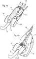
- Fig. 4 is shown a perspective view of an alternative, particularly preferred embodiment of the hand-held power tool in the form of grass shears.
- the grass shears comprises a stick holder 10, to which a driving floor 12 is connected, and which has laterally unrecognizable connecting devices, via which wheels 22, 22 'are clipped.
- a device body 13 In a device body 13, an unrecognizable drive unit and gear unit are arranged.
- the device body 13 is formed on its housing surface handlebar-like and facilitates manual triggering of the pivoting movement.
- Fig. 4a the grass shear is in a starting position
- Fig. 4b shown in a pivoted end position of the pivotable unit to the right, wherein the pivoting movement is executable as described above.
- a cutting tool 29 of the grass shear is arranged in the pivoted state vertical to the work surface and allows the edge cutting of a lawn.
- the cutting tool 29 is arranged within a wheel axis, so that the wheels 22, 22 'can at least partially run while the cutting tool 29 intersects corners / edges of the lawn.
- the drive floor 12 is connected to the stick holder 10 so that it does not come into contact with the wheels 22, 22 'either in the starting position or in the pivoted end position.
Description
Die Erfindung betrifft eine handgeführte Elektrowerkzeugmaschine sowie eine Kupplung einer handgeführten Elektrowerkzeugmaschine nach den Oberbegriffen der unabhängigen Ansprüche.The invention relates to a hand-held power tool and a coupling of a hand-held power tool according to the preambles of the independent claims.
Das Arbeiten bei handgeführten Elektrowerkzeugmaschinen kann teilweise dadurch erleichtert werden, dass ein Werkzeughalter verschwenkbar ausgebildet ist. Das Verschwenken des Werkzeugs erweist sich beispielsweise beim Schneiden von schwer zugänglichen Ästen oder zum Heckenstutzen als nützlich. Bei einer Grasschere kann ein um eine Gerätemittelachse verschwenkter Mähkopf zum Kantenschneiden eines Rasens vorteilhaft sein.Working with hand-held power tool machines can be partially facilitated by the fact that a tool holder is designed to be pivotable. The pivoting of the tool is useful, for example, when cutting hard-to-reach branches or for hedge trims. In a grass shears, a cutting head pivoted about a central axis of the device can be advantageous for edge cutting of a lawn.
Nach dem Stand der Technik ist es bekannt, einen für die geschilderte Schwenkbewegung erforderlichen manuellen Drehmechanismus über ein Kronengelenk zu arretieren, das an einem freien Ende eines mit dem Gerät verbindbaren Fahrstocks angeordnet sein kann. Als Fahrstock wird grundsätzlich ein zusätzlicher Griff verstanden, der beispielsweise in Verbindung mit Grasscheren verwendet wird. Mit aufgesteckter Grasschere ist es für den Benutzer möglich, in aufrechter Haltung in unebenem Gelände Gras zu schneiden. Ein Winkel des Drehmechanismus kann bei einem derartigen Fahrstock so verstellt werden, dass der Fahrstock aus dem Gerät herausgezogen, gedreht und wieder eingeschoben wird. Es ist auch ferner bekannt, die Arretierung über einen Rastknopf zu sichern, um ein ungewolltes Lösen des Fahrstocks zu verhindern. Der Verschwenkmechanismus des Werkzeughalters bei einer derartigen Vorrichtung ist relativ umständlich zu bedienen.According to the prior art, it is known to lock a required for the described pivoting movement manual rotary mechanism via a crown joint, which can be arranged at a free end of a connectable to the device drive block. As a driving stick is basically understood an additional handle, which is used for example in conjunction with grass shears. With attached grass shears, it is possible for the user to cut grass in an upright position on uneven terrain. An angle of the rotating mechanism can be adjusted in such a drive rack so that the drive rod is pulled out of the device, rotated and reinserted. It is also known to secure the lock via a detent button to prevent accidental release of the To prevent driving sticks. The pivoting mechanism of the tool holder in such a device is relatively cumbersome to use.
Ein derartiger Fahrstock kann mit oder ohne Rollen benutzt werden. Werden Räder in Verbindung mit einem Fahrstock verwendet, können diese zusammen mit dem Fahrstock an ein Gerät angeclipt werden. Nachteilig ist, dass dabei keine Möglichkeit besteht, einen Werkzeughalter zu verdrehen.Such an elevator can be used with or without roles. If wheels are used in conjunction with an operator's handrail, they can be clipped to a device together with the operator's handrail. The disadvantage is that there is no possibility to twist a tool holder.
Bei einer anderen handgeführten Elektrowerkzeugmaschine ist es bekannt, Räder aufzuclipen und einen Fahrstock mit dem Gerät zu verbinden. Ein Werkzeug des Geräts, beispielsweise ein Schneidkopf, kann durch Lösen eines Arretierschiebers gelöst und um einen Winkel von +/- 90° gedreht werden. Die zusätzliche Bedienung eines derartigen Schiebers ist relativ umständlich.In another hand-held power tool, it is known to clip wheels and connect a drive with the device. A tool of the device, such as a cutting head, can be solved by loosening a locking slide and rotated by an angle of +/- 90 °. The additional operation of such a slider is relatively cumbersome.
Eine andere handgeführte Elektrowerkzeugmaschine, die ein Verschwenken des Werkzeughalters ermöglicht, ist in der deutschen Patentschrift
Eine erfindungsgemäße handgeführte Elektrowerkzeugmaschine geht aus von einem Stockhalter, einen mit dem Stockhalter verbindbaren Fahrstock sowie einem Werkzeughalter. Es wird vorgeschlagen, dass zwischen dem Werkzeughalter und dem Stockhalter eine Kupplung angeordnet ist, wobei die Kupplung eine Schwenkführung aufweist, die eine relative Verdrehung zwischen dem Werkzeughalter und dem Stockhalter Dabei weist einer der beiden Halter stirnseitig zwei axial abstehende, in die Kupplung eingreifende Zapfen auf, wobei einer der Zapfen in einer als besagte Schwenkführung ausgeführte Führungsnut führbar und der andere mit der Kupplung verbundene Halter um den anderen Zapfen als Drehachse schwenkbar ist.A hand-held power tool according to the invention is based on a stick holder, a drive stick connectable to the stick holder and a tool holder. It is proposed that a coupling is arranged between the tool holder and the stick holder, wherein the coupling has a pivoting guide, the relative rotation between the tool holder and the stick holder Here, one of the two holders has two axially projecting, engaging in the coupling pin on the front side wherein one of the pins in a guided as said pivot guide guide feasible and the other connected to the coupling holder is pivotable about the other pin as a rotation axis.
Vorteilhafterweise wird mit der vorgeschlagenen Lösung ein einfach zu bedienender Schwenkmechanismus erzielt, der ohne Betätigung eines Knopfes, eines Schalters oder dgl. ausgelöst werden kann. Günstigerweise ist der Werkzeughalter so mit der Kupplung verbunden, dass er zusammen mit der Kupplung eine schwenkbare Einheit ausbilden kann. Das in dem Werkzeughalter angeordnete Werkzeug, beispielsweise eine Schere oder ein anderes Schneidgerät, wird günstigerweise zusammen mit der schwenkbaren Einheit verschwenkt.Advantageously, the proposed solution achieves an easy-to-use swivel mechanism which can be triggered without actuation of a button, a switch or the like. Conveniently, the tool holder is so with the clutch connected so that it can form a pivotal unit together with the coupling. The arranged in the tool holder tool, such as a pair of scissors or other cutting device is conveniently pivoted together with the pivoting unit.
In einer bevorzugten Ausführungsform ist die Kupplung wenigstens aus einem plattenförmigen Basiselement gebildet. Als Schwenkführung der Kupplung kann wenigstens eine Führungsnut vorgesehen sein, die mit einem korrespondierenden Zapfen des Stockhalters in Eingriff steht. Günstigerweise weist der Stockhalter stirnseitig zwei axial abstehende, in die Kupplung eingreifende Zapfen auf, wobei einer der Zapfen in der Führungsnut führbar und der mit der Kupplung verbundene Werkzeughalter um den anderen Zapfen als Drehachse schwenkbar ist. Um eine vorteilhafte Schwenkung der schwenkbaren Einheit in zwei Richtungen zu ermöglichen, sind besonders bevorzugt zwei längliche und sich X-förmig kreuzende Führungsnuten ausgebildet, etwa in der Art von zwei sich kreuzenden Sicheln. Die Drehachse der Schwenkbewegung ist dabei jeweils in Bezug auf eine Gerätemittelachse exzentrisch angeordnet. Besonders bevorzugt sind die Führungsnuten jeweils diagonal auf dem Basiselement ausgebildet. Die Führungsnuten weisen bevorzugt einen Krümmungsradius auf, der etwa einem Schwenkradius der Kupplung um jeweils einen der Zapfen als Drehpunkt entspricht.In a preferred embodiment, the coupling is formed at least from a plate-shaped base member. As a pivoting guide of the coupling can be provided at least one guide groove, which is in engagement with a corresponding pin of the stick holder. Conveniently, the stick holder frontally two axially projecting, engaging in the coupling pin, wherein one of the pins in the guide groove feasible and connected to the coupling tool holder is pivotable about the other pin as a rotation axis. In order to enable an advantageous pivoting of the pivotable unit in two directions, particularly preferably two elongate and X-shaped crossing guide grooves are formed, such as in the manner of two intersecting sickles. The axis of rotation of the pivoting movement is in each case arranged eccentrically with respect to a device center axis. Particularly preferably, the guide grooves are each formed diagonally on the base element. The guide grooves preferably have a radius of curvature which corresponds approximately to a pivot radius of the coupling about one of the pins as a fulcrum.
In einer Ausgangsposition sind die Zapfen des Stockhalters in den oberen, auseinanderklaffenden Enden der X-förmigen Führungsnuten des Basiselements eingeführt. Während der Verschwenkung können der Werkzeughalter und der Stockhalter über die Kupplung in einem Winkel von wenigstens 45° gegeneinander um eine Gerätemittelachse seitlich verdreht oder verschwenkt werden, indem die Kupplung mit einer der Führungsnuten des Basiselements entlang eines der Zapfen geführt wird, und der andere Zapfen eine Drehachse bildet. Die Schwenkbewegung kann über eine Krafteinwirkung von außen eingeleitet werden.In an initial position, the pins of the stick holder are inserted into the upper, diverging ends of the X-shaped guide grooves of the base member. During pivoting, the tool holder and the stick holder can be laterally rotated or pivoted about the coupling at an angle of at least 45 ° relative to each other about a central axis device by the coupling is guided with one of the guide grooves of the base member along one of the pins, and the other pin a Rotary axis forms. The Pivoting movement can be initiated by a force from the outside.
Besonders bevorzugt kann die Verschwenkung sowohl seitlich in eine Richtung als auch in Gegenrichtung erfolgen, wobei eine Endposition vorteilhafterweise jeweils um +/- 90° gegenüber der Anfangsposition verdrehbar ist. Dabei ist von besonderem Vorteil, dass das in den verschwenkten Werkzeughalter angeordnete Werkzeug in einem rechten Winkel zur Ausgangs-Arbeitsposition betätigt werden kann, was sich beispielsweise beim Kantenschneiden eines Rasens und dgl. als vorteilhaft erweist. Je nach Bedarf kann die schwenkbare Einheit auch in eine beliebige Zwischenposition geschwenkt werden.Particularly preferably, the pivoting can take place both laterally in one direction and in the opposite direction, wherein an end position is advantageously rotatable in each case by +/- 90 ° relative to the initial position. It is of particular advantage that the tool arranged in the pivoted tool holder can be actuated at a right angle to the initial working position, which proves to be advantageous, for example, when edging a lawn and the like. Depending on requirements, the pivoting unit can also be pivoted to any intermediate position.
In einer besonders bevorzugten Weiterbildung umfasst die Kupplung ein plattenförmiges Arretierelement mit einer zweiten Schwenkführung, die wenigstens bereichsweise deckungsungleich mit der Schwenkführung des Basiselements ist. Bevorzugt kann die Schenkführung wiederum als Führungsnut, besonders bevorzugt als zwei sich X-förmige kreuzende Führungsnuten ausgebildet sein, die zumindest bereichsweise deckungsungleich mit den Führungsnuten des Basiselements sind. Insbesondere können die Enden der Führungsnuten so ausgebildet sein, dass Arretiermittel zum Arretieren in einer Endposition ausgebildet sind, wobei die Zapfen beim Erreichen einer der Endpositionen in den Führungsnuten einrasten. Beim Zurückschwenken in die Ausgangsposition ist günstigerweise ein Anfangswiderstand zu überwinden, wodurch ein besonders bevorzugtes Arretiermittel ausgebildet wird. Nach Überwinden des Anfangswiderstands kann die schwenkbare Einheit anhand der durch Zapfen und Führungsnuten gebildeten Führung wieder definiert geschwenkt werden bis zum Erzielen einer anderen gewünschten Position, beispielsweise in der Anfangsposition. Zum Ausgleich von Relativbewegungen zwischen dem Basiselement und dem Arretierelement bzw. der Kupplung und dem Werkzeughalter kann ein Federelement angeordnet sein.In a particularly preferred development, the coupling comprises a plate-shaped locking element with a second pivoting guide which is at least partially congruent with the pivoting guide of the base element. Preferably, the Schenk guide can again be formed as a guide, particularly preferably as two X-shaped crossing guide grooves, which are at least partially congruent with the guide grooves of the base member. In particular, the ends of the guide grooves may be formed so that locking means are formed for locking in an end position, wherein the pins engage in reaching the one of the end positions in the guide grooves. When pivoting back to the starting position, an initial resistance is advantageously overcome, whereby a particularly preferred locking means is formed. After overcoming the initial resistance, the pivotal unit can be pivoted defined again based on the guide formed by pins and guide grooves until achieving another desired position, for example in the initial position. To compensate for relative movements between the base element and the locking element or the coupling and the tool holder, a spring element can be arranged.
In einer besonders bevorzugten Variante weist der Stockhalter Verbindungsvorrichtungen zur lösbaren Verbindung von Rädern auf. Die Räder können beispielsweise einfach an den Stockhalter angeclipt werden, womit der Bedienungskomfort erheblich erhöht wird. Von besonderem Vorteil ist dabei, dass die Elektrowerkzeugmaschine sowohl auf Rädern geführt werden können und gleichzeitig der Werkzeughalter verschwenkbar ist, wobei die Räder horizontal bleiben. Die Gerätemittelachse befindet sich dabei im Arbeitszustand parallel zur Arbeitsoberfläche.In a particularly preferred variant, the stick holder has connecting devices for the detachable connection of wheels. For example, the wheels can simply be clipped to the stick holder, which considerably increases the ease of use. It is particularly advantageous that the power tool can be performed both on wheels and at the same time the tool holder is pivotable, the wheels remain horizontal. The device center axis is in working condition parallel to the working surface.
Befindet sich die verschwenkte Einheit in einer der Endposition, d.h. um +/- 90° verschwenkt, ist das Werkzeug so in dem Werkzeughalter angeordnet, dass die Räder zumindest teilweise auf der Arbeitsoberfläche, beispielsweise dem Rasen, laufen können. Besonders bevorzugt ist ein Durchmesser der Räder so ausgebildet, dass sich die Räder zwar nahe am verschwenkten Werkzeug befinden, wobei jedoch vorteilhafterweise ein ungehindertes Laufen der Räder ermöglicht wird. Günstigerweise kontaktiert der Fahrstock die Räder weder in der Ausgangsposition noch in der verschwenkten Endposition.If the pivoted unit is in one of the final positions, i. pivoted by +/- 90 °, the tool is arranged in the tool holder, that the wheels can at least partially run on the work surface, such as the lawn. Particularly preferably, a diameter of the wheels is formed so that the wheels are indeed close to the pivoted tool, but advantageously allows unhindered running of the wheels is made possible. Conveniently, the drive block contacts the wheels neither in the starting position nor in the pivoted end position.
Insgesamt wird mit der vorgeschlagenen Lösung eine mit einer schwenkbaren Einheit ausgestattete Elektrowerkzeugmaschine zur Verfügung gestellt, die sich dadurch auszeichnet, dass sie besonders bedienungsfreundlich ist.Overall, provided with a pivotable unit power tool is provided with the proposed solution, which is characterized in that it is particularly easy to use.
Weitere Ausbildungsformen und Aspekte der Erfindung werden unabhängig von einer Zusammenfassung in den Patentansprüchen ohne Beschränkung der Allgemeinheit im Folgenden anhand einer Zeichnung näher erläutert.Further embodiments and aspects of the invention are explained in greater detail below with reference to a drawing, independently of a summary in the patent claims without limiting the generality.
Dabei zeigen:
- Fig. 1
- eine Ansicht einer bevorzugten Ausführungsform einer erfindungsgemäßen handgeführten Elektrowerkzeugmaschine in einer Explosionsdarstellung;
- Fig. 2
- eine perspektivische Darstellung der Elektrowerkzeugmaschine im montierten Zustand mit einem Fahrstock in einer Ausgangsposition;
- Fig. 3a,b,c
- eine Frontansicht einer bevorzugte Ausführungsform einer Kupplung in einer neutralen Ausgangsposition (
Fig. 3a ), in einer gegenüber einem Fahrstockhalter um 90° verschwenkten Endposition in einer Richtung (Fig. 3b ) und in einer anderen Richtung (Fig. 3c );und - Fig. 4a,b
- eine Darstellung einer bevorzugten Ausführungsform einer erfindungsgemäßen handgeführten Grasschere von oben in einer Ausgangsposition (
Fig. 4a ) und in einer verschwenkten Endposition (Fig. 4b ).
- Fig. 1
- a view of a preferred embodiment of a hand-held power tool according to the invention in an exploded view;
- Fig. 2
- a perspective view of the power tool in the assembled state with a drive rod in a starting position;
- Fig. 3a, b, c
- a front view of a preferred embodiment of a coupling in a neutral starting position (
Fig. 3a ), in a relative to an elevator holder by 90 ° pivoted end position in one direction (Fig. 3b ) and in another direction (Fig. 3c );and - Fig. 4a, b
- 1 is a representation of a preferred embodiment of a hand-held grass cutter according to the invention from above in an initial position (FIG.
Fig. 4a ) and in a pivoted end position (Fig. 4b ).
Gleiche Elemente werden in den Figuren gleich bezeichnet.Like elements are denoted the same in the figures.
In
Zwischen dem Werkzeughalter 11 und dem Stockhalter 10 ist eine Kupplung angeordnet. Die Kupplung weist erfindungsgemäß eine Schwenkführung auf, die eine relative Verdrehung zwischen dem Werkzeughalter 11 und dem Stockhalter 10 ermöglicht. Die Kupplung ist mittels eines Befestigungselements 26 so mit dem Werkzeughalter 11 verbunden, dass eine gegenüber dem Stockhalter 10 verschwenkbare Einheit ausgebildet wird.Between the
Die Kupplung umfasst ein im Wesentlichen plattenförmiges Basiselement 14 und ein Arretierelement 15. Beide Elemente 14, 15 weisen jeweils eine Schwenkführung auf. Bei dem plattenförmigen Basiselement 14 sind als Schwenkführung zwei sich X-förmig kreuzende Führungsnuten 16, 18 ausgebildet, die mit zwei korrespondierenden Zapfen 17, 19 des Stockhalters 10 in Eingriff stehen. Die Zapfen 17, 19 stehen stirnseitig vom Stockhalter 10 axial ab und greifen in die Kupplung ein. Der Schwenkmechanismus wird im Detail zur Figurenbeschreibung zu
Das Arretiermittel 15 ist im montierten Zustand auf der werkzeughalterseitigen Seite des Basiselements14 angeordnet und zusammen mit dem Basiselement 14 über das Befestigungsmittel 26 mit dem Werkzeughalter 11 verbunden. Das Arretierelement 15 weist eine zweite aus zwei Führungsnuten 23, 24 gebildete Schwenkführung auf, die wenigstens bereichsweise deckungsungleich mit der Schwenkführung des Basiselements 14 ist.The locking means 15 is arranged in the mounted state on the tool holder side of the
Das Befestigungselement weist zwei mit den Zapfen 17, 19 korrespondierende Ausnehmungen auf. Im verbundenen Zustand schließen der Stockhalter 10, die Teilelemente 14, 15 der Kupplung sowie der Werkzeughalter 11 am Umfang miteinander bündig ab. Das Basiselement 14 weist am unteren Rand einen flächigen Vorsprung 27 auf, der im montierten Zustand als Abdeckung dient. In zwei vertikal zur Arbeitsoberfläche, seitlich verlaufenden Ausnehmungen des Basiselements 14 sind im montierten Zustand zwei Federelemente 28, 28' angeordnet.The fastening element has two recesses corresponding to the
Der Stockhalter 10 weist seitlich zwei Verbindungsvorrichtungen 21, 21' auf zur lösbaren Verbindung von Rädern 22, 22', die in
In
In
In der Ausgangsposition greifen die Zapfen 17, 19 in die oberen, jeweils auseinanderklaffenden Enden der X-förmigen Führungsnuten 16, 18, 23, 24 ein. Die wenigstens aus dem Basiselement 14, dem Arretierelement 15 und dem nicht dargestellten Werkzeughalter 11 gebildete schwenkbare Einheit ist relativ zum Stockhalter 10 seitlich verschwenkbar.In the starting position, the
Die Schwenkbewegung nach rechts (sh.
Die Drehung in Gegenrichtung (
Die Drehzapfen 17, 19 bleiben bei den Schwenkbewegungen jeweils in Bezug auf den Halter von dem sie abstehen am Ort.The pivot pins 17, 19 remain at the pivoting movements in each case with respect to the holder from which they protrude in place.
In
Claims (10)
- Portable electric power tool, in particular grass shears, comprising at least one handle holder (10) and a tool holder (11), wherein a handle (12) is connectable to the handle holder (10), wherein a coupling is arranged between the tool holder (11) and the handle holder (10), wherein the coupling has a pivot guide that allows a relative rotation between the tool holder (11) and the handle holder (10), characterized in that one of the two holders (10, 11) has, at its end, two axially projecting pegs (17, 19) that engage in the coupling, wherein one of the pegs (17, 19) is guidable in a guide slot (16) embodied as said pivot guide and the other holder (10, 11), connected to the coupling, is pivotable about the other peg (17, 19) as axis of rotation.
- Portable electric power tool according to Claim 1, characterized in that the coupling is formed at least from a plate-form base element (14).
- Portable electric power tool according to Claim 1 or 2, characterized in that the at least one guide slot (16) is configured as pivot guide, said guide slot (16) being engaged with a corresponding peg (17) of the holder (10, 11).
- Portable electric power tool according to one of the preceding claims, characterized in that, during pivoting movements carried out by the coupling, the pegs (17, 19) remain in situ in each case with respect to the holder from which they project.
- Portable electric power tool according to one of the preceding claims, characterized in that two elongate guide slots (16, 18) that cross in an X-shaped manner are formed.
- Portable electric power tool according to one of the preceding claims, characterized in that the axis of rotation of the pivoting movement is arranged eccentrically with respect to an appliance central axis (20).
- Portable electric power tool according to one of the preceding claims, characterized in that the tool holder (11) and the handle holder (10) are pivotable laterally about the appliance central axis (20) at an angle of at least 45° to one another via the coupling.
- Portable electric power tool according to Claim 2, characterized in that the coupling comprises a plate-like locking element (15) having a second pivot guide (23, 24), which is at least regionally not congruent with the pivot guide of the base element (14).
- Portable electric power tool according to one of the preceding claims, characterized in that the handle holder (10) has connecting devices (21, 21') for releasably connecting wheels (22, 22').
- Portable electric power tool according to one of the preceding claims, characterized in that the handle holder (10) has, at its end, two axially projecting pegs (17, 19) that engage in the coupling.
Applications Claiming Priority (1)
| Application Number | Priority Date | Filing Date | Title |
|---|---|---|---|
| DE102006036634A DE102006036634A1 (en) | 2006-08-03 | 2006-08-03 | Hand-held power tool and clutch of a hand-held power tool |
Publications (2)
| Publication Number | Publication Date |
|---|---|
| EP1884156A1 EP1884156A1 (en) | 2008-02-06 |
| EP1884156B1 true EP1884156B1 (en) | 2019-05-15 |
Family
ID=38691848
Family Applications (1)
| Application Number | Title | Priority Date | Filing Date |
|---|---|---|---|
| EP07109680.4A Active EP1884156B1 (en) | 2006-08-03 | 2007-06-06 | Hand-operated electrical machine tool and coupler for a hand-operated electrical machine tool |
Country Status (4)
| Country | Link |
|---|---|
| US (1) | US20080030083A1 (en) |
| EP (1) | EP1884156B1 (en) |
| CN (1) | CN101116389B (en) |
| DE (1) | DE102006036634A1 (en) |
Families Citing this family (4)
| Publication number | Priority date | Publication date | Assignee | Title |
|---|---|---|---|---|
| PL2624680T3 (en) * | 2010-10-07 | 2017-04-28 | Husqvarna Ab | Garden cutting appliance |
| DE102012214714A1 (en) * | 2012-08-20 | 2014-02-20 | Robert Bosch Gmbh | Processing device for portable machine tool e.g. electric grass cutter of machine tool system for use in garden, has suspension unit that is releasably secured to tool receiving unit by connection unit |
| DE102012214715A1 (en) * | 2012-08-20 | 2014-02-20 | Robert Bosch Gmbh | processing device |
| EP3599311A1 (en) | 2018-07-25 | 2020-01-29 | TTI (Macao Commercial Offshore) Limited | Outdoor surface treating apparatus and associated accessory tool assembly |
Family Cites Families (20)
| Publication number | Priority date | Publication date | Assignee | Title |
|---|---|---|---|---|
| US2595413A (en) * | 1946-12-23 | 1952-05-06 | Chandler And Price Company | Curved platen printing press |
| US2795915A (en) * | 1954-09-02 | 1957-06-18 | Lawn Barber Corp | Lawn edger |
| US3490213A (en) * | 1968-03-13 | 1970-01-20 | Mcdonough Starlite Inc | Lawn edger and trimmer adjustment apparatus |
| DE6915406U (en) * | 1969-04-17 | 1969-10-09 | Riess Hans | LAWN EDGE CUTTER |
| US3824772A (en) * | 1972-01-25 | 1974-07-23 | Hahn Inc | Turf maintenance machine |
| US3816985A (en) * | 1972-01-25 | 1974-06-18 | Hahn Inc | Turf maintenance machine |
| DE2438360C2 (en) * | 1974-08-09 | 1982-06-16 | Wolf-Geräte GmbH, 5240 Betzdorf | Motor grass shears |
| AT387491B (en) * | 1974-08-09 | 1989-01-25 | Wolf Geraete Gmbh | ENGINE GRASS SHEARS |
| US4127938A (en) * | 1977-06-03 | 1978-12-05 | Slingerland Jr Henry H | Vegetation trimmer with cuttings catcher |
| US4268964A (en) * | 1979-07-02 | 1981-05-26 | Ambac Industries, Incorporated | Apparatus for cutting, trimming and edging vegetation and the like |
| DE3916145C1 (en) * | 1989-05-18 | 1990-05-23 | Wolf-Geraete Gmbh, 5240 Betzdorf, De | |
| DE3925752A1 (en) * | 1989-08-03 | 1991-02-07 | Wolf Geraete Gmbh | PRUNING SHEARS |
| US5042236A (en) * | 1990-02-08 | 1991-08-27 | The Toro Company | Cutting reel suspension with adjustable spring downloading |
| US5343680A (en) * | 1992-09-03 | 1994-09-06 | Deere & Company | Suspension mechanism for reel mowers |
| US5623817A (en) * | 1995-01-20 | 1997-04-29 | The Toro Company | Operating unit joint for turf maintenance equipment |
| US6006434A (en) * | 1997-09-30 | 1999-12-28 | Hoffco, Inc. | Quick-release component connector for lawn tool |
| US5970690A (en) * | 1997-10-24 | 1999-10-26 | Ransomes America Corporation | Leveling apparatus for a cutting head of a mower |
| US6324764B1 (en) * | 2000-03-31 | 2001-12-04 | Steven B. Watkins | Hedge trimmer assembly |
| US6412258B1 (en) * | 2000-08-31 | 2002-07-02 | Textron Inc. | Tractor-supported lawnmower having mowers movable up and down |
| CN2719010Y (en) * | 2004-05-08 | 2005-08-24 | 何海涛 | Telescopic pruning shears |
-
2006
- 2006-08-03 DE DE102006036634A patent/DE102006036634A1/en not_active Withdrawn
-
2007
- 2007-06-06 EP EP07109680.4A patent/EP1884156B1/en active Active
- 2007-07-30 US US11/830,040 patent/US20080030083A1/en not_active Abandoned
- 2007-08-02 CN CN2007101437171A patent/CN101116389B/en not_active Expired - Fee Related
Non-Patent Citations (1)
| Title |
|---|
| None * |
Also Published As
| Publication number | Publication date |
|---|---|
| CN101116389A (en) | 2008-02-06 |
| CN101116389B (en) | 2011-10-05 |
| EP1884156A1 (en) | 2008-02-06 |
| US20080030083A1 (en) | 2008-02-07 |
| DE102006036634A1 (en) | 2008-02-07 |
Similar Documents
| Publication | Publication Date | Title |
|---|---|---|
| DE4021277C2 (en) | Hand-held implement with adjustable handle | |
| EP3792009B1 (en) | Hand-guided appliance with a tool | |
| WO2006108804A1 (en) | Pliers | |
| DE202010013185U1 (en) | power tool | |
| DE102004061446A1 (en) | Razor for carrying a detachable blade unit | |
| EP2272437B1 (en) | Surgical spreading instrument | |
| EP1884156B1 (en) | Hand-operated electrical machine tool and coupler for a hand-operated electrical machine tool | |
| DE3105951A1 (en) | "POWER TOOL" | |
| DE10332918A1 (en) | thread cutter | |
| EP0434781B1 (en) | Electrically powered hand-held shears for lawns | |
| DE202016105276U1 (en) | Cutting tool, in particular hedge trimmer | |
| DE112022001852T5 (en) | Garden tool | |
| DE19926375A1 (en) | Motorized garden tools, in particular hedge trimmers | |
| EP2798931B1 (en) | Fan rake | |
| DE2839780A1 (en) | Hedge trimmer with removable cutter blades - has removable cover on active end of cutter blades fitted by bayonet-type slide catches | |
| DE202008012053U1 (en) | secateurs | |
| WO2016116179A1 (en) | Handle device | |
| EP1661447A1 (en) | Lawn trimmer | |
| DE202009002224U1 (en) | Edge cutter with gimbal handle | |
| EP0038014B1 (en) | Electrically driven instruments, especially garden instruments | |
| DE1553797C (en) | Secateurs, in particular lawn shears | |
| WO1990010594A1 (en) | Vehicle jack | |
| EP3420793B1 (en) | Device for adjusting the position of a spar of a moving device | |
| WO2009029970A1 (en) | Cutting apparatus with at least one moveable cutting head which can be driven by a motor | |
| DE202006018090U1 (en) | machine tool |
Legal Events
| Date | Code | Title | Description |
|---|---|---|---|
| PUAI | Public reference made under article 153(3) epc to a published international application that has entered the european phase |
Free format text: ORIGINAL CODE: 0009012 |
|
| AK | Designated contracting states |
Kind code of ref document: A1 Designated state(s): AT BE BG CH CY CZ DE DK EE ES FI FR GB GR HU IE IS IT LI LT LU LV MC MT NL PL PT RO SE SI SK TR |
|
| AX | Request for extension of the european patent |
Extension state: AL BA HR MK YU |
|
| 17P | Request for examination filed |
Effective date: 20080806 |
|
| 17Q | First examination report despatched |
Effective date: 20080904 |
|
| AKX | Designation fees paid |
Designated state(s): DE FR GB |
|
| GRAP | Despatch of communication of intention to grant a patent |
Free format text: ORIGINAL CODE: EPIDOSNIGR1 |
|
| INTG | Intention to grant announced |
Effective date: 20180822 |
|
| RIN1 | Information on inventor provided before grant (corrected) |
Inventor name: MUELLER-BOYSEN, ULRICH Inventor name: BANTLE, FLORIAN |
|
| GRAS | Grant fee paid |
Free format text: ORIGINAL CODE: EPIDOSNIGR3 |
|
| GRAA | (expected) grant |
Free format text: ORIGINAL CODE: 0009210 |
|
| AK | Designated contracting states |
Kind code of ref document: B1 Designated state(s): DE FR GB |
|
| REG | Reference to a national code |
Ref country code: GB Ref legal event code: FG4D Free format text: NOT ENGLISH |
|
| REG | Reference to a national code |
Ref country code: DE Ref legal event code: R096 Ref document number: 502007016680 Country of ref document: DE |
|
| REG | Reference to a national code |
Ref country code: DE Ref legal event code: R097 Ref document number: 502007016680 Country of ref document: DE |
|
| PLBE | No opposition filed within time limit |
Free format text: ORIGINAL CODE: 0009261 |
|
| STAA | Information on the status of an ep patent application or granted ep patent |
Free format text: STATUS: NO OPPOSITION FILED WITHIN TIME LIMIT |
|
| 26N | No opposition filed |
Effective date: 20200218 |
|
| PGFP | Annual fee paid to national office [announced via postgrant information from national office to epo] |
Ref country code: FR Payment date: 20200623 Year of fee payment: 14 |
|
| PGFP | Annual fee paid to national office [announced via postgrant information from national office to epo] |
Ref country code: GB Payment date: 20200625 Year of fee payment: 14 |
|
| REG | Reference to a national code |
Ref country code: DE Ref legal event code: R084 Ref document number: 502007016680 Country of ref document: DE |
|
| GBPC | Gb: european patent ceased through non-payment of renewal fee |
Effective date: 20210606 |
|
| PG25 | Lapsed in a contracting state [announced via postgrant information from national office to epo] |
Ref country code: GB Free format text: LAPSE BECAUSE OF NON-PAYMENT OF DUE FEES Effective date: 20210606 |
|
| PG25 | Lapsed in a contracting state [announced via postgrant information from national office to epo] |
Ref country code: FR Free format text: LAPSE BECAUSE OF NON-PAYMENT OF DUE FEES Effective date: 20210630 |
|
| PGFP | Annual fee paid to national office [announced via postgrant information from national office to epo] |
Ref country code: DE Payment date: 20230817 Year of fee payment: 17 |