EP2550435B1 - Plant for the production of energy based upon the organic rankine cycle. - Google Patents
Plant for the production of energy based upon the organic rankine cycle. Download PDFInfo
- Publication number
- EP2550435B1 EP2550435B1 EP11710150.1A EP11710150A EP2550435B1 EP 2550435 B1 EP2550435 B1 EP 2550435B1 EP 11710150 A EP11710150 A EP 11710150A EP 2550435 B1 EP2550435 B1 EP 2550435B1
- Authority
- EP
- European Patent Office
- Prior art keywords
- turbine
- plant
- production
- organic
- energy
- Prior art date
- Legal status (The legal status is an assumption and is not a legal conclusion. Google has not performed a legal analysis and makes no representation as to the accuracy of the status listed.)
- Active
Links
Images
Classifications
-
- F—MECHANICAL ENGINEERING; LIGHTING; HEATING; WEAPONS; BLASTING
- F01—MACHINES OR ENGINES IN GENERAL; ENGINE PLANTS IN GENERAL; STEAM ENGINES
- F01K—STEAM ENGINE PLANTS; STEAM ACCUMULATORS; ENGINE PLANTS NOT OTHERWISE PROVIDED FOR; ENGINES USING SPECIAL WORKING FLUIDS OR CYCLES
- F01K23/00—Plants characterised by more than one engine delivering power external to the plant, the engines being driven by different fluids
- F01K23/02—Plants characterised by more than one engine delivering power external to the plant, the engines being driven by different fluids the engine cycles being thermally coupled
- F01K23/06—Plants characterised by more than one engine delivering power external to the plant, the engines being driven by different fluids the engine cycles being thermally coupled combustion heat from one cycle heating the fluid in another cycle
- F01K23/08—Plants characterised by more than one engine delivering power external to the plant, the engines being driven by different fluids the engine cycles being thermally coupled combustion heat from one cycle heating the fluid in another cycle with working fluid of one cycle heating the fluid in another cycle
-
- F—MECHANICAL ENGINEERING; LIGHTING; HEATING; WEAPONS; BLASTING
- F01—MACHINES OR ENGINES IN GENERAL; ENGINE PLANTS IN GENERAL; STEAM ENGINES
- F01K—STEAM ENGINE PLANTS; STEAM ACCUMULATORS; ENGINE PLANTS NOT OTHERWISE PROVIDED FOR; ENGINES USING SPECIAL WORKING FLUIDS OR CYCLES
- F01K23/00—Plants characterised by more than one engine delivering power external to the plant, the engines being driven by different fluids
- F01K23/02—Plants characterised by more than one engine delivering power external to the plant, the engines being driven by different fluids the engine cycles being thermally coupled
- F01K23/04—Plants characterised by more than one engine delivering power external to the plant, the engines being driven by different fluids the engine cycles being thermally coupled condensation heat from one cycle heating the fluid in another cycle
-
- F—MECHANICAL ENGINEERING; LIGHTING; HEATING; WEAPONS; BLASTING
- F01—MACHINES OR ENGINES IN GENERAL; ENGINE PLANTS IN GENERAL; STEAM ENGINES
- F01K—STEAM ENGINE PLANTS; STEAM ACCUMULATORS; ENGINE PLANTS NOT OTHERWISE PROVIDED FOR; ENGINES USING SPECIAL WORKING FLUIDS OR CYCLES
- F01K7/00—Steam engine plants characterised by the use of specific types of engine; Plants or engines characterised by their use of special steam systems, cycles or processes; Control means specially adapted for such systems, cycles or processes; Use of withdrawn or exhaust steam for feed-water heating
- F01K7/02—Steam engine plants characterised by the use of specific types of engine; Plants or engines characterised by their use of special steam systems, cycles or processes; Control means specially adapted for such systems, cycles or processes; Use of withdrawn or exhaust steam for feed-water heating the engines being of multiple-expansion type
-
- F—MECHANICAL ENGINEERING; LIGHTING; HEATING; WEAPONS; BLASTING
- F22—STEAM GENERATION
- F22B—METHODS OF STEAM GENERATION; STEAM BOILERS
- F22B1/00—Methods of steam generation characterised by form of heating method
- F22B1/006—Methods of steam generation characterised by form of heating method using solar heat
-
- F—MECHANICAL ENGINEERING; LIGHTING; HEATING; WEAPONS; BLASTING
- F22—STEAM GENERATION
- F22B—METHODS OF STEAM GENERATION; STEAM BOILERS
- F22B1/00—Methods of steam generation characterised by form of heating method
- F22B1/02—Methods of steam generation characterised by form of heating method by exploitation of the heat content of hot heat carriers
- F22B1/16—Methods of steam generation characterised by form of heating method by exploitation of the heat content of hot heat carriers the heat carrier being hot liquid or hot vapour, e.g. waste liquid, waste vapour
- F22B1/167—Methods of steam generation characterised by form of heating method by exploitation of the heat content of hot heat carriers the heat carrier being hot liquid or hot vapour, e.g. waste liquid, waste vapour using an organic fluid
Description
- The present invention relates to a plant for the production of energy based upon the organic Rankine cycle (ORC), in particular a plant for the production of energy comprising a plurality of cascaded ORC systems that use particular turbines.
- As is known, ORC plants are systems generally used for simultaneous production of electrical and thermal energy, the latter being made available in the form of water at the temperature of 60 - 90°C. Organic Rankine cycles are similar to the cycles used by traditional steam turbines, except for the operating fluid, which, normally, is an organic fluid with high molecular mass.
- A typical ORC plant is substantially made up of a pump, a turbine, and some heat exchangers. The organic operating fluid is vaporized by using a heat source in the evaporator. The steam of the organic fluid expands in the turbine and is then condensed generally using a flow of water in a heat exchanger. The condensed liquid is finally sent via a pump into the evaporator thus closing the cycle. In order to increase the yield of the plant it is possible to envisage the use of a regenerator. In this case, the fluid leaving the turbine traverses a regenerator before being condensed and, once condensed, is pumped into the regenerator, where it is pre-heated by the fluid leaving the turbine, before being sent to the evaporator.
- Generally, these plants are used for the production of energy with waste fluids coming from a wide range of industrial and energy-generating processes (cogeneration engines and turbines, furnaces of all types, chimneys of petrochemical plants, sources of geothermal nature, etc.), characterized by a temperature jump that is potentially high but by flows that are on average limited or in any case variable in time or, otherwise, by high flows associated, however, to a low temperature level.
- The energy vector used for vaporization of the organic fluid is in general diathermic oil (mineral oil, or synthetic oil for temperatures above 300°C) or water, whereas for condensation water is used. The use of diathermic oil moreover prevents the need to use highpressure boilers.
- The operating fluid is generally constituted by an organic compound or by a mixture of organic compounds, characterized by a high molecular weight. The choice of the organic fluid to be used for optimizing the yield of the thermodynamic cycle is made according to the temperature of the heat source available. In addition, also the turbine must normally be designed according to the characteristics of the organic fluid and to the operating conditions.
- Consequently, it is evident that the application of ORC systems is subject to limits and critical aspects deriving from the thermal power available as primary source, from the temperature level/levels (quality of the source), and from the stability and/or relative variability in time of the thermal load.
- It is moreover evident that current ORC systems are far from flexible and far from adaptable to different operating conditions given that, as previously mentioned, both the choice of the organic operating fluid and the characteristics of the turbine are markedly dependent upon the operating conditions.
- Examples of ORC systems of known type are described in
US 6 035 643 andUS 5 860 279 . The purpose of the present invention is consequently to provide a plant for the production of electrical energy based upon the organic Rankine cycle (ORC) that will be able to eliminate or reduce the aforementioned drawbacks. - In particular, a purpose of the present invention is to provide a plant of an ORC type for the production of electrical energy that will enable maximization of the yield in terms of electrical energy produced.
- Another purpose of the present invention is to provide a plant of an ORC type for the production of electrical energy that will be readily adaptable to different operating conditions. Yet another purpose of the present invention is to provide a plant of an ORC type for the production of electrical energy that will enable optimal characteristics of yield to be maintained even during a drop inefficiency of the primary flow.
- A further purpose of the present invention is to provide a plant of an ORC type for the production of electrical energy that will present a small number of parts, and will be easy to produce at competitive costs.
- In accordance with the present invention, the above-mentioned purposes are achieved by a plant for the production of energy based upon the organic Rankine cycle (ORC), which is characterized in that it comprises a first ORC system comprising a first organic operating fluid circulating, in sequence, between a first evaporator in conditions of heat exchange with a heat source, a first expansion stage in a turbine operatively connected to a generator, a first evaporator/condenser, and a first pump for recirculating said first organic operating fluid to said first evaporator. A further peculiar characteristic of the plant according to the invention is represented by the fact that said turbine is a partializable turbine comprising means for partializing the incoming flowrate of said organic operating fluids, said means being designed to partialize said incoming flowrate to maintain the revolutions per minute of said turbine constant, said means for partializing the incoming flowrate of said organic operating fluids comprising a hydraulic device driven by the corresponding organic operating fluid. Preferably, the plant for the production of energy according to the invention comprises a second ORC system, which comprises a second organic operating fluid circulating, in sequence, between said first evaporator/condenser, a second expansion stage in a turbine operatively connected to a generator, a second evaporator/condenser, and a second pump for recirculating said second organic operating fluid to said first evaporator/condenser, said turbine comprising, for each of said stages, means for partializing the incoming flowrate of said organic fluids.
- The plant according to the invention enables a considerable series of advantages to be achieved as compared to the ORC systems of a known type.
- In practice, in the case of the multistage organic Rankine cycle, the system is characterized by a series of successive enthalpic jumps performed not by a single fluid within various rotor-stator assemblies of a turbine (e.g., the water vapour that expands at various levels of pressure in the stages of a turbine), but by a number of fluids, each operating on a number of pressure and temperature levels, within their own turbine, which is coupled, axially aligned or in parallel, to the turbine for the other fluids that together with it constitute the system. The plant hence comprises a so-called "primary" fluid, which interfaces with the heat source, and an appropriate number of secondary fluids, ordered in such a way that the condensation of the previous one causes evaporation of the next one, in order to recover the maximum possible amount of energy available to the source, yielding the minimum fraction thereof into the environment.
- The limit of quality of the source (e.g., low enthalpic level) obviously dictates the limits of application of the technology. The availability and the temperature of the cooling fluid define, instead, the lower-limit stage, enabling, with the use of organic fluids and binary mixtures for low-temperature applications, extension of the discharge from the last turbine to levels theoretically lower than thermal zero.
- By way of example, for the most frequent cases of high temperature and low flowrate of the power source it is preferable for the operating fluid of the primary circuit to have a rather high molecular weight so as to exploit to the full the high temperatures that can present at discharge (typically, 500-900°C). The flowrate of said fluid is, however, in this case limited by the thermal power effectively available, and this circumstance is a first limiting factor on the power produced by the primary fluid.
- A second factor, which is no less important, is the molecular weight itself of the fluid. A high molecular weight, which advantageously enables the high temperatures of the heat source to be pursued, proves a penalizing factor in terms of enthalpic jump in the turbine and condensation temperature. For example, if this fluid at the evaporator is able, with not excessively high pressures (20-40 bar), to vaporize at quite high temperatures (250-350°C), at the condenser, albeit with pressures far higher than 1 bar, still comes out at rather high temperatures, in the region of 160-250°C. Hence, with the first operating fluid, with a low flowrate, and a limited enthalpic jump in the turbine, a low power is normally obtained, in the region of 15% of the one available at discharge.
- However, the still significantly high temperatures of the primary fluid undergoing condensation, and the phase thereof selected for heat exchange with very high coefficients of transmission, enable use of a secondary operating fluid that will recover entirely or partially the heat of condensation of the first fluid, and will perform an altogether independent Rankine cycle, producing a further, significant amount of electric power. In fact, assuming the value of 15% referred to previously as yield of the primary cycle means that of 100 kW at input for the first fluid there remain 85 kW available for the second organic operating fluid. Choosing the latter with characteristics such as to be optimal for working at lower operating temperatures and with a range of pressures similar to those of the first fluid, said fluid will operate on lower isotherms, guaranteeing in any case a similar yield. Assuming then again a 15% recovery means that, out of 85 kW available, a further 12.75 kW are obtained, for a total of 27.75 kW, which is the theoretical yield of a plant that works with just two "cascaded" fluids.
- Hence, extrapolating the concept, there may be readily envisaged the possibility of using a third fluid, or in general "n" fluids, which, by working in cascaded fashion, i.e., as has been said, with the evaporation on the condensation of the previous one, optimize the entire, process limiting to a minimum the heat yielded by the last condensation, which is the one that is then discharged into the environment, and thus maximizing the total yield.
- In the plant for the production of energy according to the invention, said means for partializing the incoming flowrate of said organic operating fluids comprise, for each of said stages, a hydraulic device driven by the corresponding organic operating fluid.
- In addition, advantageously, said partializable turbine is a multistage turbine, with single shaft or separate shafts, axially aligned or with parallel axes.
- A preferred embodiment of the plant for the production of energy according to the present invention envisages that said heat source will comprise heat-accumulation means.
- For example, said heat-accumulation means can comprise a refractory-mass accumulation system or a molten-salt closed-circuit battery.
- A further preferred embodiment of the plant for the production of energy according to the present invention envisages that said heat source comprises means for integration of the available energy.
- For example, said means for integration of the available energy comprise a thermodynamic solar-energy system.
- A particular embodiment of the plant for the production of energy according to the present invention envisages the presence of a device for mechanical coupling between said turbine and said generator.
- Said device for mechanical coupling between said turbine and said generator can, for example, comprise a reducer, a flywheel governor, and a brake set between the shaft of said turbine and the shaft of said generator.
- An alternative embodiment of the plant for the production of energy according to the present invention envisages, instead, that said turbine is directly coupled to said generator, said plant further comprising electronic means for conversion of the output voltage of said generator.
- Further characteristics and advantages of the present invention will emerge from the description of preferred, though not exclusive, embodiments of a plant for the production of energy based upon the organic Rankine cycle (ORC), illustrated by way of non-limiting example in the annexed drawings, in which:
-
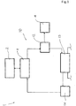
Figure 1 shows a diagram of a general embodiment of a plant according to the present invention; -
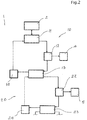
Figure 2 shows a diagram of a first particular embodiment of a plant according to the present invention; -
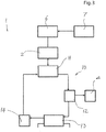
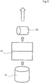
Figure 3 shows a diagram of a second particular embodiment of a plant according to the present invention; -
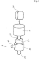
Figure 4 is a schematic representation of a first embodiment of the mechanical coupling between a turbine and a generator in a plant according to the present invention; and -
Figure 5 is a schematic representation of an embodiment of the coupling to the electrical mains of a plant according to the present invention. - With reference to the attached figures, a plant for the production of energy based upon the organic Rankine cycle (ORC) according to the present invention, designated as a whole by the reference number 1, in its more general embodiment illustrated in
Figure 1 , comprises at least onefirst ORC system 10. - Said
first ORC system 10 in turn comprises a first organic operating fluid that circulates, in sequence, between afirst evaporator 11 in conditions of heat exchange with a heat source 2, afirst expansion stage 12 in a turbine operatively connected to agenerator 4, a first evaporator/condenser 13 and afirst pump 14 for recirculating said first organic operating fluid to saidfirst evaporator 11. - Preferably, as illustrated in
Figure 2 , the plant 1 for the production of energy according to the present invention, comprises asecond ORC system 20, which in turn comprises a second organic operating fluid circulating, in sequence, between said first evaporator/condenser 13, asecond expansion stage 22 in a turbine operatively connected to a generator 5, a second evaporator/condenser 23, and asecond pump 24 for recirculating said second organic operating fluid to said first evaporator/condenser 13, said turbine comprising, for each of saidstages - Basically, as has already been mentioned, the plant comprises at least two organic operating fluids, which, working in cascaded fashion (namely, with the evaporation of the second fluid on the condensation of the first fluid), optimize the entire process, limiting to a minimum the heat yielded by the last condensation.
- In other words, using this scheme, the closed-circuit organic Rankine cycle uses the primary source of energy for converting the first fluid into steam, the expansion in the turbine converts this heat accumulated by the steam into kinetic energy, which in turn will become electrical energy. In the cascade the condenser becomes the primary source for the second fluid, and so forth for a possible third stage and subsequent stages.
- By applying the principle illustrated in the attached
Figure 2 , it is in fact possible to extend said concepts to a plant that comprises a third ORC system, which includes a third organic operating fluid that circulates, in sequence, between said second evaporator/condenser, a third expansion stage in a turbine operatively connected to a corresponding generator, a third evaporator/condenser, and a third pump for recirculating said first organic operating fluid to said second evaporator/condenser. In general, this principle can then be extended to a plant that comprises "n" further ORC systems. - One of the peculiar characteristics of the plant 1 according to the present invention is represented by the fact that said turbine is a partializable turbine and comprises means for partializing the incoming flowrate of said organic operating fluids. In particular, said partialization means are designed to partialize said inlet flowrate to maintain the r.p.m. of said turbine constant.
- It has in fact been seen that, using a turbine of the type described above, it is possible to maintain the optimal characteristics of yield even during a drop of efficiency of the primary flow. Thanks to the automatic partialization of the flowrate, the r.p.m. of the turbine is, in fact, kept constant, which is an extremely important aspect for achieving maximum yield.
- In practice, partialization of the turbine through the control of incoming flowrate in order to keep the r.p.m. of the shaft constant, enables the level of electrical yield to be kept constant irrespective of the load, thus contributing to the maximum exploitation of the source of thermal power in every condition that arises upstream.
- The application of a process of a cascaded type finds justification in the very nature of the heat exchange and of the characteristics of the power fluid. In fact, it is precisely the first exchanger of the system, the evaporator of the primary fluid with highest enthalpy, the one that is most critical given that it is interfaced with the waste fluids, which each time present low coefficients of heat exchange, high corrosiveness, and non-constancy of the flowrate.
- Using a cascaded system, it is possible to concentrate the process of heat recovery in this first exchanger, which constitutes the central element of the entire cycle both in terms of efficiency and in terms of costs.
- The subsequent condensers-evaporators are favoured by the cascaded functional logic and by the nature of the fluids adopted, both in the efficiency of interchange and in the nature of the design and manufacturing materials required, thus involving small surfaces and hence low costs. According to the invention, said means for partializing the incoming flowrate of said organic operating fluids comprise a hydraulic device driven by the corresponding organic operating fluid. In this way, the flowrate at inlet to said organic operating fluids is adjusted exploiting the variations of pressure of the organic fluids themselves.
- In addition, advantageously, said partializable turbine can be a multistage turbine, with single shaft or with separate shafts, axially aligned or with parallel axes.
- A particular embodiment of the plant 1 for the production of energy according to the present invention, illustrated in
Figure 3 , is characterized in that said heat source 2 comprises heat-accumulation means 6. - In the case where the plant of the present invention is applied to industrial processes with production of intermittent waste in the short period, there may arise in fact the need to stabilize the thermal flow at levels compatible with the stepwise regulation of the plant.
- There may consequently arise the following situations:
- expedience of limiting the load with re-use of part thereof for optimization of the consumption correlated to the basic production processes;
- expedience, if not strict need for regulation of the ORC unit downstream, of proceeding to a partial accumulation of the heat available to stabilize the thermal flow at homogeneous levels.
- By using the heat-accumulation means 6, which comprise, for example, a refractory-mass accumulation system or a molten-salt closed-circuit battery, it is possible to maintain an average thermal level guaranteed of the heat source 2, managing the situations described above in an optimal way.
- For low thermal powers a refractory-mass accumulation system with low impact from the economic and maintenance standpoints is preferable. In this case, the hot process fluid traverses the refractory material until its own thermal load is reduced to the value at input to the high-temperature evaporator. When the flowrate of the waste fluid is reduced and/or is about to cease, a closed-circuit circulation of hot air (or recirculation of the gas itself) is activated between the accumulation chamber and the evaporator. For applications of this type, the optimal accumulation temperature range is between 200°C and 400°C.
- For high powers, the accumulation system may conveniently be based upon a closed-circuit molten-salt battery, also according to the economic aspects of the investment required for the accumulation tank in the light of the effective thermal capacity that can be recovered and hence of the corresponding electrical production.
- The aggressiveness of the molten salts requires a limitation of the temperature of the mixtures (nitrates and nitrides of sodium, potassium and calcium) to values of 400-450°C to enable use of low-cost materials for heat exchangers and tanks. Furthermore, to prevent combination of the effects of aggressiveness of the salts with the source fluid it is expedient to use an intermediate vector fluid of a diathermic type. Finally, the choice of technologies of exchangers that ensure low loss of head for viscous fluids ('EM-Baffle®' technology, and the like) completes the requirements of the system.
- A further particular embodiment of the plant 1 for the production of energy according to the present invention, illustrated once again in
Figure 3 , envisages that said heat source 2 comprisesmeans 7 for integration of the available energy. - Both using the refractory-mass system and the molten-salt system, as likewise other accumulation systems, it is in fact possible to integrate the power available so as to ensure the enthalpic jump within the organic Rankine cycle. Said integration can be obtained through re-use of part of the electrical power produced for stabilizing the cycle and/or achieving maximum thermodynamic yield thereof. It is likewise possible to increase the absolute power thereof through the use of parallel sources according to the time of day and the demand. Specifically, technologies applied to the thermodynamic solar sector can, for example, be used to increase the available flowrate adequately during periods of peak demand.
- Coupling of the energy-integration means to the power-accumulation means ensures maximum flexibility of the entire cycle, duly exploiting the stepwise operation of the turbine, as illustrated previously in the case of cascaded multistage organic Rankine cycles. Both the accumulation means 6 and the integration means 7 can in fact be conveniently applied to plants comprising a plurality of organic Rankine cycles of the type illustrated in
Figure 2 . - The plant 1 for the production of energy according to the present invention can moreover comprise means for electrical transduction, namely, for the transformation of the kinetic energy developed by the turbine into electrical energy.
- For example, with reference to the attached
Figure 4 , the plant 1 for the production of energy according to the present invention can advantageously comprise a mechanical-coupling device 8 between said turbine and saidgenerator 4, 5. - Said mechanical-
coupling device 8 can, for example, comprise areducer 81 set between the shaft 84 of said turbine and the shaft 85 of saidgenerator 4, 5. Saidreducer 81 can, for example, be a reducer of an epicyclic type in such a way as to guarantee reduction of r.p.m. from the turbine to the generator (alternator), thus maintaining the right frequency for output the energy produced to the mains. - Furthermore, the
reducer 81 conveniently comprises all the elements (for example, a flywheel governor 82 and a brake 83) that will enable maintenance of the correct working points of the entire system. The connection with the mains can be made via a transformer 86 and/or other means for synchronization with said mains. - Alternatively, as illustrated in
Figure 5 , said turbine is directly coupled to saidgenerator 4, 5. For example, the turbine can be directly coupled to a (synchronous or asynchronous) motor, eliminating the entire mechanical block described previously. In this case, said device can be used in the four quadrants (Vxl > 0; Vxl < 0) both as motor for entering the transients of the turbine and exiting therefrom and as electric generator. - In this case, electronic means 9 are present, for example an AC/DC converter for continuous conversion of the high-frequency voltage (frequencies much higher than 50 Hz) given by the direct coupling with the turbine, as well as a DC/AC converter to obtain the right output voltage with the appropriate synchronism for output into the mains. Transformer means 91 may likewise be conveniently present.
- It is clear from the foregoing description that the plant for the production of energy according to the present invention fully achieves the pre-set task and purposes.
- The partialization of the turbine responds in fact to the scenarios of thermal load that can vary according to pre-defined steps, where alternative options of use of the power are available or, more directly, for adapting to reduction of the demand, whatever the origin of said reduction.
- Said application consequently constitutes an effective response, for example in the cases of cogeneration coupled to partializable generators, the cycle of which finds itself pursuing the load in steps (down to a minimum of less than 50% of the nominal size), and/or enabling an increase in the global production of electricity to destine the entire thermal load available to said production (e.g., absence of use or reduced use of hot water/steam in non-winter periods and non-primary interest in trigeneration).
- Coupling with a secondary heat source (e.g., solar concentration source) moreover enables exploitation of the turbine at its maximum level of power, reducing the primary consumption or simply increasing the global production of electricity in the periods of increasing demand.
- Finally, the accumulation of power enables balancing of the production in time and, once again, maximization of the production within the limit of the power effectively available, during periods of increasing demand.
- From the foregoing it may hence be stated that the plant for the production of energy according to the present invention, in particular when it combines cascaded organic Rankine cycles, downstream of an accumulation-integration plant, with partializable turbines, presents as ideal from the technical and economic standpoints for maximization of the yield of production of electrical energy from waste and/or sources of heat of medium-to-low absolute power of any nature.
- On the basis of the foregoing description, other characteristics, modifications, or improvements are possible and evident to the average person skilled in the sector. In practice, the materials, used as well as the contingent dimensions and shapes, may be any according to the requirements and the state of the art.
Claims (10)
- A plant (1) for the production of energy based upon the organic Rankine cycle (ORC), characterized in that it comprises a first ORC system (10) comprising a first organic operating fluid circulating, in sequence, between a first evaporator (11) in conditions of heat exchange with a heat source (2), a first expansion stage (12) in a turbine operatively connected to a generator (4), a first evaporator/condenser (13), and a first pump (14) for recirculating said first organic operating fluid to said first evaporator (11); said turbine being a partializable turbine and comprising means for partializing the incoming flowrate of said organic operating fluid, said means being able to partialize said inlet flowrate to maintain the revolutions per minute of said turbine constant, said means for partializing the incoming flowrate of said organic operating fluids comprising a hydraulic device driven by the organic operating fluid.
- The plant (1) for the production of energy according to Claim 1, characterized in that it comprises a second ORC system (20), comprising a second organic operating fluid circulating, in sequence, between said first evaporator/condenser (13), a second expansion stage (22) in a turbine operatively connected to a generator (5), a second evaporator/condenser (23), and a second pump (24) for recirculating said second organic operating fluid to said first evaporator/condenser (13), said turbine comprising, for each of said stages (12, 22), means for partializing the incoming flowrate of said organic fluids.
- The plant (1) for the production of energy according to Claim 1 or Claim 2, characterized in that said partializable turbine is a multistage turbine, with single shaft or with separate shafts, axially aligned or with parallel axes.
- The plant (1) for the production of energy according to one or more of the preceding claims, characterized in that said heat source (2) comprises heat-accumulation means (6).
- The plant (1) for the production of energy according to Claim 4, characterized in that said heat-accumulation means (6) comprise a refractory-mass accumulation system or a closed-circuit molten-salt battery.
- The plant (1) for the production of energy according to one or more of the preceding claims, characterized in that said heat source (2) comprises means (7) for integration of the available energy.
- The plant (1) for the production of energy according to Claim 6, characterized in that said means (7) for integration of the available energy comprise a thermodynamic solar-energy system.
- The plant (1) for the production of energy according to one or more of the preceding claims, characterized in that it comprises a device (8) for mechanical coupling between said turbine and said generator (4, 5).
- The plant (1) for the production of energy according to Claim 8, characterized in that said mechanical-coupling device (8) between said turbine and said generator (4, 5) comprises a reducer (81), a flywheel governor (82), and a brake (83) set between the shaft (84) of said turbine and the shaft (85) of said generator (4, 5).
- The plant (1) for the production of energy according to one or more of Claims 1 to 7, characterized in that said turbine is directly coupled to said generator (4, 5), said plant (1) comprising electronic means (9) for conversion of the output voltage of said generator (4, 5).
Priority Applications (1)
| Application Number | Priority Date | Filing Date | Title |
|---|---|---|---|
| PL11710150T PL2550435T3 (en) | 2010-03-25 | 2011-03-09 | Plant for the production of energy based upon the organic rankine cycle. |
Applications Claiming Priority (2)
| Application Number | Priority Date | Filing Date | Title |
|---|---|---|---|
| ITBG2010A000015A IT1400467B1 (en) | 2010-03-25 | 2010-03-25 | PLANT FOR ENERGY PRODUCTION BASED ON THE RANKINE CYCLE WITH ORGANIC FLUID. |
| PCT/EP2011/053527 WO2011117074A1 (en) | 2010-03-25 | 2011-03-09 | Plant for the production of energy based upon the organic rankine cycle. |
Publications (2)
| Publication Number | Publication Date |
|---|---|
| EP2550435A1 EP2550435A1 (en) | 2013-01-30 |
| EP2550435B1 true EP2550435B1 (en) | 2018-08-22 |
Family
ID=43607991
Family Applications (1)
| Application Number | Title | Priority Date | Filing Date |
|---|---|---|---|
| EP11710150.1A Active EP2550435B1 (en) | 2010-03-25 | 2011-03-09 | Plant for the production of energy based upon the organic rankine cycle. |
Country Status (12)
| Country | Link |
|---|---|
| US (1) | US20130014509A1 (en) |
| EP (1) | EP2550435B1 (en) |
| CN (1) | CN102834590B (en) |
| BR (1) | BR112012024305A8 (en) |
| CA (1) | CA2792680A1 (en) |
| DK (1) | DK2550435T3 (en) |
| EA (1) | EA035787B1 (en) |
| ES (1) | ES2696520T3 (en) |
| IT (1) | IT1400467B1 (en) |
| PL (1) | PL2550435T3 (en) |
| PT (1) | PT2550435T (en) |
| WO (1) | WO2011117074A1 (en) |
Families Citing this family (14)
| Publication number | Priority date | Publication date | Assignee | Title |
|---|---|---|---|---|
| CN107327327B (en) * | 2011-08-19 | 2020-04-17 | 科慕埃弗西有限公司 | Methods and compositions for organic rankine cycles producing mechanical energy from heat |
| CN103161529A (en) * | 2011-12-12 | 2013-06-19 | 邵再禹 | Closed circulation electricity generation method canceling working medium backwash pump |
| US8984884B2 (en) * | 2012-01-04 | 2015-03-24 | General Electric Company | Waste heat recovery systems |
| US9018778B2 (en) | 2012-01-04 | 2015-04-28 | General Electric Company | Waste heat recovery system generator varnishing |
| US9024460B2 (en) | 2012-01-04 | 2015-05-05 | General Electric Company | Waste heat recovery system generator encapsulation |
| CN102979588B (en) * | 2012-10-29 | 2015-03-11 | 昆明理工大学 | Photovoltaic and organic Rankine cycle coupling combined heat and power supply system |
| GB2521430A (en) | 2013-12-19 | 2015-06-24 | Ibm | Device and method for converting heat into mechanical energy |
| RU2560607C1 (en) * | 2014-04-07 | 2015-08-20 | Федеральное государственное бюджетное образовательное учреждение высшего профессионального образования "Казанский государственный энергетический университет" (ФГБОУ ВПО "КГЭУ") | Heat power plant operation mode |
| CN105179033B (en) * | 2015-08-12 | 2017-05-31 | 中国科学院工程热物理研究所 | The system and its operation method of a kind of utilization cryogenic cold energy storage electric energy |
| CN105114138B (en) * | 2015-08-12 | 2016-08-31 | 中国科学院工程热物理研究所 | A kind of low temperature energy-storing and power-generating system and operation method thereof |
| CN105641962B (en) * | 2016-03-15 | 2018-03-23 | 山东科灵节能装备股份有限公司 | Falling film evaporator and the organic Rankine cycle power generation system using the falling film evaporator |
| CN110131115A (en) * | 2019-05-31 | 2019-08-16 | 深圳大学 | The compound cascaded power generating system of middle low temperature underground heat ORC magnetic suspension |
| CN110159377A (en) * | 2019-05-31 | 2019-08-23 | 深圳大学 | In cryogenically hot working fluid cascade utilization ORC magnetic suspension generation system |
| CN111577417A (en) * | 2020-05-28 | 2020-08-25 | 中国船舶工业集团公司第七0八研究所 | Supercritical two-stage cascade Rankine cycle power generation system on FSRU |
Citations (1)
| Publication number | Priority date | Publication date | Assignee | Title |
|---|---|---|---|---|
| US2407982A (en) * | 1943-09-15 | 1946-09-24 | Westinghouse Electric Corp | Acceleration-responsive governor system |
Family Cites Families (14)
| Publication number | Priority date | Publication date | Assignee | Title |
|---|---|---|---|---|
| US2878785A (en) * | 1958-04-10 | 1959-03-24 | Gen Electric | Hydraulic speed governing system with reset relay |
| US4069669A (en) * | 1976-08-18 | 1978-01-24 | Pitkanen Alan R | Inertial turbine energy storage braking and power transmission system |
| ES8607515A1 (en) * | 1985-01-10 | 1986-06-16 | Mendoza Rosado Serafin | Process for mechanical power generation |
| US4903490A (en) * | 1988-10-14 | 1990-02-27 | Westinghouse Electric Corp. | Cam-driven valve system for steam turbines |
| NZ248730A (en) * | 1992-10-02 | 1996-03-26 | Ormat Ind Ltd | High pressure geothermal power plant with primary steam turbine and at least one power plant module having low pressure turbine |
| US5860279A (en) * | 1994-02-14 | 1999-01-19 | Bronicki; Lucien Y. | Method and apparatus for cooling hot fluids |
| US6035643A (en) * | 1998-12-03 | 2000-03-14 | Rosenblatt; Joel H. | Ambient temperature sensitive heat engine cycle |
| US6960839B2 (en) * | 2000-07-17 | 2005-11-01 | Ormat Technologies, Inc. | Method of and apparatus for producing power from a heat source |
| DE10355782B4 (en) * | 2003-11-26 | 2006-04-27 | Maxxtec Ag | Apparatus and method for carrying out a thermal cycle |
| US7665304B2 (en) * | 2004-11-30 | 2010-02-23 | Carrier Corporation | Rankine cycle device having multiple turbo-generators |
| US7942001B2 (en) * | 2005-03-29 | 2011-05-17 | Utc Power, Llc | Cascaded organic rankine cycles for waste heat utilization |
| CH697550B1 (en) * | 2005-03-30 | 2008-11-28 | Alstom Technology Ltd | Method for controlling a frequency converter. |
| US7775045B2 (en) * | 2005-10-31 | 2010-08-17 | Ormat Technologies, Inc. | Method and system for producing power from a source of steam |
| US20090179429A1 (en) * | 2007-11-09 | 2009-07-16 | Erik Ellis | Efficient low temperature thermal energy storage |
-
2010
- 2010-03-25 IT ITBG2010A000015A patent/IT1400467B1/en active
-
2011
- 2011-03-09 EA EA201290947A patent/EA035787B1/en not_active IP Right Cessation
- 2011-03-09 PL PL11710150T patent/PL2550435T3/en unknown
- 2011-03-09 PT PT11710150T patent/PT2550435T/en unknown
- 2011-03-09 US US13/636,827 patent/US20130014509A1/en not_active Abandoned
- 2011-03-09 CA CA2792680A patent/CA2792680A1/en not_active Abandoned
- 2011-03-09 ES ES11710150T patent/ES2696520T3/en active Active
- 2011-03-09 EP EP11710150.1A patent/EP2550435B1/en active Active
- 2011-03-09 WO PCT/EP2011/053527 patent/WO2011117074A1/en active Application Filing
- 2011-03-09 BR BR112012024305A patent/BR112012024305A8/en not_active Application Discontinuation
- 2011-03-09 CN CN201180015672.4A patent/CN102834590B/en not_active Expired - Fee Related
- 2011-03-09 DK DK11710150.1T patent/DK2550435T3/en active
Patent Citations (1)
| Publication number | Priority date | Publication date | Assignee | Title |
|---|---|---|---|---|
| US2407982A (en) * | 1943-09-15 | 1946-09-24 | Westinghouse Electric Corp | Acceleration-responsive governor system |
Also Published As
| Publication number | Publication date |
|---|---|
| EP2550435A1 (en) | 2013-01-30 |
| CA2792680A1 (en) | 2011-09-29 |
| IT1400467B1 (en) | 2013-06-11 |
| ITBG20100015A1 (en) | 2011-09-26 |
| ES2696520T3 (en) | 2019-01-16 |
| BR112012024305A2 (en) | 2016-05-24 |
| PT2550435T (en) | 2018-11-28 |
| US20130014509A1 (en) | 2013-01-17 |
| EA201290947A1 (en) | 2013-04-30 |
| WO2011117074A1 (en) | 2011-09-29 |
| BR112012024305A8 (en) | 2018-01-02 |
| CN102834590B (en) | 2015-05-20 |
| EA035787B1 (en) | 2020-08-11 |
| DK2550435T3 (en) | 2018-12-10 |
| PL2550435T3 (en) | 2019-02-28 |
| CN102834590A (en) | 2012-12-19 |
Similar Documents
| Publication | Publication Date | Title |
|---|---|---|
| EP2550435B1 (en) | Plant for the production of energy based upon the organic rankine cycle. | |
| US9322295B2 (en) | Thermal energy storage unit with steam and gas turbine system | |
| EP2182179B1 (en) | Thermoelectric energy storage system and method for storing thermoelectric energy | |
| CN1317486C (en) | Integrated micro combined heat and power system | |
| EP2241737B1 (en) | Thermoelectric energy storage system having two thermal baths and method for storing thermoelectric energy | |
| AU2010326107B2 (en) | Utilizing steam and/or hot water generated using solar energy | |
| EP2751395B1 (en) | Cascaded power plant using low and medium temperature source fluid | |
| EP2930319B1 (en) | Rankine cycle device operation method | |
| WO2011045282A2 (en) | Thermoelectric energy storage system having an internal heat exchanger and method for storing thermoelectric energy | |
| WO2011147701A1 (en) | Thermoelectric energy storage system and method for storing thermoelectric energy | |
| US20170002695A1 (en) | Organic rankine binary cycle power generation system | |
| AU2008349706A1 (en) | Method for operating a thermodynamic circuit, as well as a thermodynamic circuit | |
| AU2013231164B2 (en) | An organic rankine cycle for mechanical drive applications | |
| US11274575B2 (en) | Gas turbine plant and operation method therefor | |
| WO2011030285A1 (en) | Method and apparatus for electrical power production | |
| JP2016061227A (en) | Cooling facility, combined cycle plant including the same, and cooling method | |
| RU2722436C2 (en) | Cascade cycle and method of regenerating waste heat | |
| JP5527513B2 (en) | Fluid machine drive system | |
| Sung et al. | An organic Rankine cycle for two different heat sources: steam and hot water | |
| EP4083393A1 (en) | Cogenerative organic rankine cycle with vapor extraction from the turbine | |
| Nandal | Energy, Exergy, and Losses in Components of a Coal Thermal Power Plant | |
| PL229331B1 (en) | System for cogeneration of electrical energy and heating of water, powered from renewable energy sources |
Legal Events
| Date | Code | Title | Description |
|---|---|---|---|
| PUAI | Public reference made under article 153(3) epc to a published international application that has entered the european phase |
Free format text: ORIGINAL CODE: 0009012 |
|
| 17P | Request for examination filed |
Effective date: 20120926 |
|
| AK | Designated contracting states |
Kind code of ref document: A1 Designated state(s): AL AT BE BG CH CY CZ DE DK EE ES FI FR GB GR HR HU IE IS IT LI LT LU LV MC MK MT NL NO PL PT RO RS SE SI SK SM TR |
|
| DAX | Request for extension of the european patent (deleted) | ||
| RAP1 | Party data changed (applicant data changed or rights of an application transferred) |
Owner name: NRG GREEN & RECOVERY POWER SYSTEMS SPA |
|
| RIN1 | Information on inventor provided before grant (corrected) |
Inventor name: NRG GREEN & RECOVERY POWER SYSTEMS SPA |
|
| 17Q | First examination report despatched |
Effective date: 20151207 |
|
| GRAP | Despatch of communication of intention to grant a patent |
Free format text: ORIGINAL CODE: EPIDOSNIGR1 |
|
| STAA | Information on the status of an ep patent application or granted ep patent |
Free format text: STATUS: GRANT OF PATENT IS INTENDED |
|
| INTG | Intention to grant announced |
Effective date: 20180528 |
|
| GRAS | Grant fee paid |
Free format text: ORIGINAL CODE: EPIDOSNIGR3 |
|
| GRAA | (expected) grant |
Free format text: ORIGINAL CODE: 0009210 |
|
| STAA | Information on the status of an ep patent application or granted ep patent |
Free format text: STATUS: THE PATENT HAS BEEN GRANTED |
|
| AK | Designated contracting states |
Kind code of ref document: B1 Designated state(s): AL AT BE BG CH CY CZ DE DK EE ES FI FR GB GR HR HU IE IS IT LI LT LU LV MC MK MT NL NO PL PT RO RS SE SI SK SM TR |
|
| REG | Reference to a national code |
Ref country code: GB Ref legal event code: FG4D |
|
| RIN1 | Information on inventor provided before grant (corrected) |
Inventor name: NASINI, ERNESTO Inventor name: ROTTOLI, MARCO Inventor name: PERICO, COSTANZO |
|
| REG | Reference to a national code |
Ref country code: CH Ref legal event code: EP |
|
| REG | Reference to a national code |
Ref country code: AT Ref legal event code: REF Ref document number: 1032778 Country of ref document: AT Kind code of ref document: T Effective date: 20180915 |
|
| REG | Reference to a national code |
Ref country code: IE Ref legal event code: FG4D |
|
| REG | Reference to a national code |
Ref country code: DE Ref legal event code: R096 Ref document number: 602011051266 Country of ref document: DE |
|
| REG | Reference to a national code |
Ref country code: PT Ref legal event code: SC4A Ref document number: 2550435 Country of ref document: PT Date of ref document: 20181128 Kind code of ref document: T Free format text: AVAILABILITY OF NATIONAL TRANSLATION Effective date: 20181115 Ref country code: NL Ref legal event code: FP |
|
| REG | Reference to a national code |
Ref country code: DK Ref legal event code: T3 Effective date: 20181203 |
|
| REG | Reference to a national code |
Ref country code: LT Ref legal event code: MG4D |
|
| REG | Reference to a national code |
Ref country code: ES Ref legal event code: FG2A Ref document number: 2696520 Country of ref document: ES Kind code of ref document: T3 Effective date: 20190116 |
|
| PG25 | Lapsed in a contracting state [announced via postgrant information from national office to epo] |
Ref country code: NO Free format text: LAPSE BECAUSE OF FAILURE TO SUBMIT A TRANSLATION OF THE DESCRIPTION OR TO PAY THE FEE WITHIN THE PRESCRIBED TIME-LIMIT Effective date: 20181122 Ref country code: IS Free format text: LAPSE BECAUSE OF FAILURE TO SUBMIT A TRANSLATION OF THE DESCRIPTION OR TO PAY THE FEE WITHIN THE PRESCRIBED TIME-LIMIT Effective date: 20181222 Ref country code: RS Free format text: LAPSE BECAUSE OF FAILURE TO SUBMIT A TRANSLATION OF THE DESCRIPTION OR TO PAY THE FEE WITHIN THE PRESCRIBED TIME-LIMIT Effective date: 20180822 Ref country code: SE Free format text: LAPSE BECAUSE OF FAILURE TO SUBMIT A TRANSLATION OF THE DESCRIPTION OR TO PAY THE FEE WITHIN THE PRESCRIBED TIME-LIMIT Effective date: 20180822 Ref country code: GR Free format text: LAPSE BECAUSE OF FAILURE TO SUBMIT A TRANSLATION OF THE DESCRIPTION OR TO PAY THE FEE WITHIN THE PRESCRIBED TIME-LIMIT Effective date: 20181123 Ref country code: FI Free format text: LAPSE BECAUSE OF FAILURE TO SUBMIT A TRANSLATION OF THE DESCRIPTION OR TO PAY THE FEE WITHIN THE PRESCRIBED TIME-LIMIT Effective date: 20180822 Ref country code: BG Free format text: LAPSE BECAUSE OF FAILURE TO SUBMIT A TRANSLATION OF THE DESCRIPTION OR TO PAY THE FEE WITHIN THE PRESCRIBED TIME-LIMIT Effective date: 20181122 Ref country code: LT Free format text: LAPSE BECAUSE OF FAILURE TO SUBMIT A TRANSLATION OF THE DESCRIPTION OR TO PAY THE FEE WITHIN THE PRESCRIBED TIME-LIMIT Effective date: 20180822 |
|
| REG | Reference to a national code |
Ref country code: AT Ref legal event code: MK05 Ref document number: 1032778 Country of ref document: AT Kind code of ref document: T Effective date: 20180822 |
|
| PG25 | Lapsed in a contracting state [announced via postgrant information from national office to epo] |
Ref country code: AL Free format text: LAPSE BECAUSE OF FAILURE TO SUBMIT A TRANSLATION OF THE DESCRIPTION OR TO PAY THE FEE WITHIN THE PRESCRIBED TIME-LIMIT Effective date: 20180822 Ref country code: HR Free format text: LAPSE BECAUSE OF FAILURE TO SUBMIT A TRANSLATION OF THE DESCRIPTION OR TO PAY THE FEE WITHIN THE PRESCRIBED TIME-LIMIT Effective date: 20180822 Ref country code: LV Free format text: LAPSE BECAUSE OF FAILURE TO SUBMIT A TRANSLATION OF THE DESCRIPTION OR TO PAY THE FEE WITHIN THE PRESCRIBED TIME-LIMIT Effective date: 20180822 |
|
| PG25 | Lapsed in a contracting state [announced via postgrant information from national office to epo] |
Ref country code: EE Free format text: LAPSE BECAUSE OF FAILURE TO SUBMIT A TRANSLATION OF THE DESCRIPTION OR TO PAY THE FEE WITHIN THE PRESCRIBED TIME-LIMIT Effective date: 20180822 Ref country code: RO Free format text: LAPSE BECAUSE OF FAILURE TO SUBMIT A TRANSLATION OF THE DESCRIPTION OR TO PAY THE FEE WITHIN THE PRESCRIBED TIME-LIMIT Effective date: 20180822 Ref country code: AT Free format text: LAPSE BECAUSE OF FAILURE TO SUBMIT A TRANSLATION OF THE DESCRIPTION OR TO PAY THE FEE WITHIN THE PRESCRIBED TIME-LIMIT Effective date: 20180822 |
|
| REG | Reference to a national code |
Ref country code: DE Ref legal event code: R097 Ref document number: 602011051266 Country of ref document: DE |
|
| PG25 | Lapsed in a contracting state [announced via postgrant information from national office to epo] |
Ref country code: SK Free format text: LAPSE BECAUSE OF FAILURE TO SUBMIT A TRANSLATION OF THE DESCRIPTION OR TO PAY THE FEE WITHIN THE PRESCRIBED TIME-LIMIT Effective date: 20180822 Ref country code: SM Free format text: LAPSE BECAUSE OF FAILURE TO SUBMIT A TRANSLATION OF THE DESCRIPTION OR TO PAY THE FEE WITHIN THE PRESCRIBED TIME-LIMIT Effective date: 20180822 |
|
| PLBE | No opposition filed within time limit |
Free format text: ORIGINAL CODE: 0009261 |
|
| STAA | Information on the status of an ep patent application or granted ep patent |
Free format text: STATUS: NO OPPOSITION FILED WITHIN TIME LIMIT |
|
| 26N | No opposition filed |
Effective date: 20190523 |
|
| PG25 | Lapsed in a contracting state [announced via postgrant information from national office to epo] |
Ref country code: SI Free format text: LAPSE BECAUSE OF FAILURE TO SUBMIT A TRANSLATION OF THE DESCRIPTION OR TO PAY THE FEE WITHIN THE PRESCRIBED TIME-LIMIT Effective date: 20180822 |
|
| PG25 | Lapsed in a contracting state [announced via postgrant information from national office to epo] |
Ref country code: MC Free format text: LAPSE BECAUSE OF FAILURE TO SUBMIT A TRANSLATION OF THE DESCRIPTION OR TO PAY THE FEE WITHIN THE PRESCRIBED TIME-LIMIT Effective date: 20180822 |
|
| REG | Reference to a national code |
Ref country code: CH Ref legal event code: PL |
|
| PG25 | Lapsed in a contracting state [announced via postgrant information from national office to epo] |
Ref country code: LU Free format text: LAPSE BECAUSE OF NON-PAYMENT OF DUE FEES Effective date: 20190309 |
|
| PG25 | Lapsed in a contracting state [announced via postgrant information from national office to epo] |
Ref country code: LI Free format text: LAPSE BECAUSE OF NON-PAYMENT OF DUE FEES Effective date: 20190331 Ref country code: CH Free format text: LAPSE BECAUSE OF NON-PAYMENT OF DUE FEES Effective date: 20190331 Ref country code: IE Free format text: LAPSE BECAUSE OF NON-PAYMENT OF DUE FEES Effective date: 20190309 |
|
| PG25 | Lapsed in a contracting state [announced via postgrant information from national office to epo] |
Ref country code: TR Free format text: LAPSE BECAUSE OF FAILURE TO SUBMIT A TRANSLATION OF THE DESCRIPTION OR TO PAY THE FEE WITHIN THE PRESCRIBED TIME-LIMIT Effective date: 20180822 |
|
| PG25 | Lapsed in a contracting state [announced via postgrant information from national office to epo] |
Ref country code: MT Free format text: LAPSE BECAUSE OF NON-PAYMENT OF DUE FEES Effective date: 20190309 |
|
| PGFP | Annual fee paid to national office [announced via postgrant information from national office to epo] |
Ref country code: PT Payment date: 20210222 Year of fee payment: 11 Ref country code: CZ Payment date: 20210225 Year of fee payment: 11 |
|
| PG25 | Lapsed in a contracting state [announced via postgrant information from national office to epo] |
Ref country code: CY Free format text: LAPSE BECAUSE OF FAILURE TO SUBMIT A TRANSLATION OF THE DESCRIPTION OR TO PAY THE FEE WITHIN THE PRESCRIBED TIME-LIMIT Effective date: 20180822 |
|
| PGFP | Annual fee paid to national office [announced via postgrant information from national office to epo] |
Ref country code: PL Payment date: 20210219 Year of fee payment: 11 Ref country code: BE Payment date: 20210329 Year of fee payment: 11 Ref country code: DK Payment date: 20210329 Year of fee payment: 11 |
|
| PG25 | Lapsed in a contracting state [announced via postgrant information from national office to epo] |
Ref country code: HU Free format text: LAPSE BECAUSE OF FAILURE TO SUBMIT A TRANSLATION OF THE DESCRIPTION OR TO PAY THE FEE WITHIN THE PRESCRIBED TIME-LIMIT; INVALID AB INITIO Effective date: 20110309 |
|
| PGFP | Annual fee paid to national office [announced via postgrant information from national office to epo] |
Ref country code: NL Payment date: 20210326 Year of fee payment: 11 |
|
| PG25 | Lapsed in a contracting state [announced via postgrant information from national office to epo] |
Ref country code: MK Free format text: LAPSE BECAUSE OF FAILURE TO SUBMIT A TRANSLATION OF THE DESCRIPTION OR TO PAY THE FEE WITHIN THE PRESCRIBED TIME-LIMIT Effective date: 20180822 |
|
| REG | Reference to a national code |
Ref country code: DK Ref legal event code: EBP Effective date: 20220331 |
|
| PG25 | Lapsed in a contracting state [announced via postgrant information from national office to epo] |
Ref country code: PT Free format text: LAPSE BECAUSE OF NON-PAYMENT OF DUE FEES Effective date: 20220909 Ref country code: CZ Free format text: LAPSE BECAUSE OF NON-PAYMENT OF DUE FEES Effective date: 20220309 |
|
| REG | Reference to a national code |
Ref country code: NL Ref legal event code: MM Effective date: 20220401 |
|
| REG | Reference to a national code |
Ref country code: BE Ref legal event code: MM Effective date: 20220331 |
|
| PG25 | Lapsed in a contracting state [announced via postgrant information from national office to epo] |
Ref country code: NL Free format text: LAPSE BECAUSE OF NON-PAYMENT OF DUE FEES Effective date: 20220401 |
|
| PG25 | Lapsed in a contracting state [announced via postgrant information from national office to epo] |
Ref country code: BE Free format text: LAPSE BECAUSE OF NON-PAYMENT OF DUE FEES Effective date: 20220331 |
|
| PG25 | Lapsed in a contracting state [announced via postgrant information from national office to epo] |
Ref country code: DK Free format text: LAPSE BECAUSE OF NON-PAYMENT OF DUE FEES Effective date: 20220331 |
|
| PGFP | Annual fee paid to national office [announced via postgrant information from national office to epo] |
Ref country code: FR Payment date: 20230327 Year of fee payment: 13 |
|
| PGFP | Annual fee paid to national office [announced via postgrant information from national office to epo] |
Ref country code: IT Payment date: 20230320 Year of fee payment: 13 Ref country code: GB Payment date: 20230327 Year of fee payment: 13 Ref country code: DE Payment date: 20230329 Year of fee payment: 13 |
|
| P01 | Opt-out of the competence of the unified patent court (upc) registered |
Effective date: 20230420 |
|
| PGFP | Annual fee paid to national office [announced via postgrant information from national office to epo] |
Ref country code: ES Payment date: 20230403 Year of fee payment: 13 |
|
| PG25 | Lapsed in a contracting state [announced via postgrant information from national office to epo] |
Ref country code: PL Free format text: LAPSE BECAUSE OF NON-PAYMENT OF DUE FEES Effective date: 20220309 |