EP2550199B1 - An einer taumelscheibe montierter permanentmagnet-generator - Google Patents
An einer taumelscheibe montierter permanentmagnet-generator Download PDFInfo
- Publication number
- EP2550199B1 EP2550199B1 EP20110759964 EP11759964A EP2550199B1 EP 2550199 B1 EP2550199 B1 EP 2550199B1 EP 20110759964 EP20110759964 EP 20110759964 EP 11759964 A EP11759964 A EP 11759964A EP 2550199 B1 EP2550199 B1 EP 2550199B1
- Authority
- EP
- European Patent Office
- Prior art keywords
- swashplate
- rotating
- magnet
- electrical
- rotating ring
- Prior art date
- Legal status (The legal status is an assumption and is not a legal conclusion. Google has not performed a legal analysis and makes no representation as to the accuracy of the status listed.)
- Not-in-force
Links
- 238000004804 winding Methods 0.000 claims description 12
- 238000000034 method Methods 0.000 claims description 10
- 230000005465 channeling Effects 0.000 claims description 4
- 230000008901 benefit Effects 0.000 description 4
- 230000004907 flux Effects 0.000 description 4
- 238000011161 development Methods 0.000 description 3
- 230000018109 developmental process Effects 0.000 description 3
- 238000012986 modification Methods 0.000 description 3
- 230000004048 modification Effects 0.000 description 3
- 238000012360 testing method Methods 0.000 description 2
- RZVHIXYEVGDQDX-UHFFFAOYSA-N 9,10-anthraquinone Chemical compound C1=CC=C2C(=O)C3=CC=CC=C3C(=O)C2=C1 RZVHIXYEVGDQDX-UHFFFAOYSA-N 0.000 description 1
- 229910000640 Fe alloy Inorganic materials 0.000 description 1
- 239000000956 alloy Substances 0.000 description 1
- 238000004891 communication Methods 0.000 description 1
- 238000004590 computer program Methods 0.000 description 1
- 239000004020 conductor Substances 0.000 description 1
- 238000010276 construction Methods 0.000 description 1
- 238000007796 conventional method Methods 0.000 description 1
- 238000003745 diagnosis Methods 0.000 description 1
- 238000007689 inspection Methods 0.000 description 1
- 238000012423 maintenance Methods 0.000 description 1
- 239000000463 material Substances 0.000 description 1
- 238000012544 monitoring process Methods 0.000 description 1
- 238000012546 transfer Methods 0.000 description 1
Images


Classifications
-
- B—PERFORMING OPERATIONS; TRANSPORTING
- B64—AIRCRAFT; AVIATION; COSMONAUTICS
- B64C—AEROPLANES; HELICOPTERS
- B64C27/00—Rotorcraft; Rotors peculiar thereto
- B64C27/54—Mechanisms for controlling blade adjustment or movement relative to rotor head, e.g. lag-lead movement
- B64C27/58—Transmitting means, e.g. interrelated with initiating means or means acting on blades
- B64C27/59—Transmitting means, e.g. interrelated with initiating means or means acting on blades mechanical
- B64C27/605—Transmitting means, e.g. interrelated with initiating means or means acting on blades mechanical including swash plate, spider or cam mechanisms
-
- B—PERFORMING OPERATIONS; TRANSPORTING
- B64—AIRCRAFT; AVIATION; COSMONAUTICS
- B64D—EQUIPMENT FOR FITTING IN OR TO AIRCRAFT; FLIGHT SUITS; PARACHUTES; ARRANGEMENT OR MOUNTING OF POWER PLANTS OR PROPULSION TRANSMISSIONS IN AIRCRAFT
- B64D41/00—Power installations for auxiliary purposes
-
- Y—GENERAL TAGGING OF NEW TECHNOLOGICAL DEVELOPMENTS; GENERAL TAGGING OF CROSS-SECTIONAL TECHNOLOGIES SPANNING OVER SEVERAL SECTIONS OF THE IPC; TECHNICAL SUBJECTS COVERED BY FORMER USPC CROSS-REFERENCE ART COLLECTIONS [XRACs] AND DIGESTS
- Y02—TECHNOLOGIES OR APPLICATIONS FOR MITIGATION OR ADAPTATION AGAINST CLIMATE CHANGE
- Y02T—CLIMATE CHANGE MITIGATION TECHNOLOGIES RELATED TO TRANSPORTATION
- Y02T50/00—Aeronautics or air transport
- Y02T50/40—Weight reduction
Definitions
- the present application relates generally to swashplates, and more specifically, to a swashplate having an alternator.
- a swashplate is a device that translates flight control input to the rotary system.
- Alternators are adapted to convert mechanical energy into electrical energy, which in turn is channeled to one or more electrical subsystems.
- the alternator is an effective means for converting mechanical energy from the aircraft engine to electrical energy for powering the aircraft electrical subsystems.
- the aircraft alternator is typically positioned near the engine, which creates problems when channeling the electrical energy to one or more electrical subsystems located on rotary system due to the continuous swashplate rotation.
- Slip ring and/or other suitable devices are typically used when transferring the electrical energy through the rotary system.
- WO2005/100154 A1 discloses a rotor for mounting on a helicopter drive shaft, comprising a hub for location on the shaft and a plurality of blades mounted to and extending out from the hub, wherein a pitch angle of at least one of the blades is controllable with respect to each other blade by an electrical stepper motor mechanism arranged at the hub. Also disclosed is a method for determining a pitch angle of the blades of the rotor, a computer program arranged to, when loaded onto a computing system, utilise an algorithm for determining blade pitch angle values for the blades, an alternator for providing power to motors that control the pitch of the blades and a control method for implementation by a computer in controlling the pitch of the blades in real time.
- US5646467 discloses an axial air gap motor comprising a housing having a first endplate and an opposed second endplate, a stator assembly mounted within the housing, and a rotor assembly rotatable mounted within the housing.
- the rotor assembly includes an annular disc shaped armature, wherein the armature includes a front facing surface and a rear facing surface.
- the stator assembly includes a first magnetic permeable flux return plate secured to the first endplate and a magnet assembly secured to the first flux return plate.
- the magnet assembly is positioned between the first flux return plate and the front facing surface of said armature for directing a magnetic field to said armature in a direction normal to a plane of said armature.
- the stator further including a magnetic permeable second flux return plate secured to the second endplate.
- the swashplate system of the present application overcomes common disadvantages associated with conventional methods and devices for transferring electrical energy from the alternator to one or more electrical subsystems positioned on a rotary system. Illustrative embodiments are described below. It will of course be appreciated that in the development of any actual embodiment, numerous implementation-specific decisions will be made to achieve the developer's specific goals, such as compliance with system-related and business-related constraints, which will vary from one implementation to another. Moreover, it will be appreciated that such a development effort might be complex and time-consuming, but would nevertheless be a routine undertaking for those of ordinary skill in the art having the benefit of this disclosure.
- Rotary aircraft 101 comprises one or more of a rotor system 103 having rotors 105 operably associated with a swatchplate system 107.
- Swatchplate system 107 is adapted to selectively pitch and pivot rotors 105, which in turn changes the aerodynamic performance of aircraft 101.
- swashplate system 107 is adapted to provide the same maneuverability, i.e., rotation, pivoting, tilting, and/or other movements about the rotor shaft as conventional swatchplate systems commonly known in the art.
- the simplified depiction of swashplate system 107 should not be narrowly construed as having the exact geometric contouring as shown in the drawings, unless specified, but should be construed as having the necessary contouring, size, and other geometric profiling to perform the necessary operation as a conventional swatchplate.
- the necessary components such as bearings, bolts, liners, and other necessary components of a swashplate system are not shown in order to quickly and easily describe the swashplate system of the present application; however, it should be understood that the swashplate system of the present invention includes all necessary components to operate as a swashplate, as conventionally known in the art, although not shown in the drawings.
- swashplate system 107 is used with a rotary aircraft, i.e., a helicopter; however, it should be appreciated that the swashplate system could easily be adapted for use with a tilt-wing aircraft, in lieu of the preferred embodiment. Also, swashplate system 107 is utilized with the main rotor system of the rotary aircraft; however, it should be appreciated that the swashplate system could easily be adapted for use with other rotor systems, including the tail rotor system, as well as aircraft having multiple main rotors such as a tandem rotary aircraft. It will be appreciated that swashplate system 107 eliminates dedicated wires passing through the mast; and also eliminates the need for a slip-ring, which greatly reduces added weight to aircraft 101.
- Aircraft 101 is further provided with an alternator subsystem 109 adapted to convert mechanical energy from rotor system 103 to electrical energy and transfer the electric energy to one or more electrical subsystems 111 and/or other power consuming devices operably associated with rotary aircraft 101.
- alternator subsystem 109 creates and provides electrical energy to one or more electrical subsystems associated with rotor system 103; however, it should be appreciated that alternator subsystem 109 could easily be adapted to provide electrical energy to one or more electrical subsystems carried by aircraft 101.
- alternator system 109 could be adapted to provide electrical energy to an electrical subsystem located within the aircraft fuselage.
- Electrical subsystem 111 is preferably a sensor selectively positioned on one or more components of rotor system 103 for providing real time monitoring of the rotary system.
- the sensors enable easy and rapid diagnosis of rotor system 103, which in turn reduces aircraft downtime and associated costs due to routine maintenance inspections.
- alternative embodiments of electrical subsystem 111 could include different electrical devices in lieu of the preferred embodiment.
- alternative embodiments could include lights, warning devices, and/or other suitable devices operably associated with rotary system 103.
- Swashplate system 107 comprises one or more of an inner ring 201 and an outer ring 203. It should be understood that outer ring 203 is adapted to rotate about rotary shaft 205, while inner ring 201 remains stationary about shaft 205.
- alternator subsystem 109 comprises rotating and non-rotating components carried by and coupled to outer ring 203 and inner ring 201, respectively. Further illustration and description of alternator subsystem 109 is provided below.
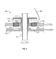
- Figure 3 shows a cross-sectional side view of the swashplate system 107 of Figure 2 taken at III-III.
- Alternator subsystem 109 preferably comprises one or more of first non-rotating magnet member 301, an opposing non-rotating magnet member 303, and a rotating winding member 305 disposed therebetween.
- Non-rotating members 301 and 303 securely attach to a portion 307 of inner ring 201 via an attachment means 309, i.e., a bolt, while rotating member 305 securely attaches to outer ring 203 via an attachment means 311, i.e., a bolt.
- portion 307 is an upper bearing guide, which is supported by inner ring 201. It will be appreciated that alternative embodiments could include other devices or structures, either supported by or attached to inner ring 201, which are adapted to couple to non-rotating members 301 and 303.
- Non-rotating member 301 is provided with one or more magnets 313; and likewise, non-rotating member 303 is provided with one or more opposing magnets 315 selectively positioned in polar opposite to magnets 313.
- the space between non-rotating members 301 and 303 preferably remains at a small distance to increase the efficiency of alternator subsystem 109. In the preferred embodiment, the space is about 0.050 inch; however, alternative embodiments could include different lengths depending on the desired application.
- magnets 313 and magnets 315 are arranged such that the magnet poles are in an alternating orientation, i.e. north and then south, in relation to each other.
- magnets 313 and magnet 315 are manufactured with about an inch square in length and with a thickness of about 0.5 inch; however, these lengths and thicknesses can vary depending on the desired application.
- Winding member 305 is provided with one or more coils of wire 317 selectively positioned between magnets 313 and magnets 315 such that a side of coils 317 faces magnets 313 and the opposing side of coils 317 faces magnets 315.
- Coils 317 comprise a base 319 for holding a length of a metallic wire 321.
- winding member 305 comprises eighteen coils 317 of conductive wire 321; however, the number of coils could vary in alternative embodiments depending on the desired performance. It should be understood that an electrical current is created within coils 317 upon passing through the magnetic field. Thereafter, the electrical current is channeled to one or more electrical subsystems 111.
- Winding member 305 is further provided with an optional rectifier 323 attached to a side surface 325 and conductively coupled to wire 321 and a wire 327. It should be understood that in some embodiments rectifier 323 is not required. Wire 327 is conductively coupled to electrical subsystem 111, thereby providing channeling means for transferring electrical energy alternator system 109 to electrical subsystem 111. Winding member 305 preferably rotates at approximately 400 RPM; however, it will be appreciated that rotor systems generally have unique RPM speeds, thus creating different electrical voltage output to electrical subsystem 111.
- Swashplate system 107 is preferably configured as a 3-phase system, but may also be configured in a variety of phases depending on the arrangement of magnets, coils, and related circuitry.
- Alternator subsystem 109 allows for electrical energy to be produced using an existing rotating and non-rotating interface. Alternator subsystem 109 creates sufficient electrical power for powering one or more electrical subsystems 111. It will be appreciated that electrical subsystems 111 could be adapted with associated electrical devices that enables wireless communication with other electrical subsystems either carried by or detached from rotary aircraft 101. For example, an electrical subsystem could include a transmitter for relaying real time data to receiver carried by the aircraft fuselage, which transmits real time data of the aircraft performance to the pilot. It should also be appreciated that if alternator subsystem 109 is properly constructed and assembled, the lack of direct contact between the non-rotating members and rotating member enables alternator system 109 to have an unlimited service life.
- alternator subsystem 109 includes coils sandwiched between a first and second set of magnets; however, it should be appreciated that alternator subsystem 109 could include additional coils and magnets to modify the electrical output of alternator subsystem 109.
- an alternative embodiment could include a magnet, coil, magnet, magnet, coil, and magnet sandwiched configuration or a magnet, coil, magnet, coil, and magnet sandwiched configuration.
- the aircraft engine (not shown) rotates a rotor shaft 205, which in turn rotates rotors 105.
- One or more driver links operably associated with rotors 105 rotate outer ring 203, which in turn rotates winding member 305.
- An electrical voltage is created as coils 317 of winding member 305 pass through the magnetic field created by magnets 313 and 315 of non-rotating members 301 and 303, respectively. Thereafter, the electrical voltage is channeled through wire 321 to rectifier 323. Rectifier 323 conditions and rectifies the electrical voltage, which in turn is channeled to electrical subsystem 111 via wire 327.
- Non-rotating magnet member 301 comprises one or more of base 401, outer ring 403 protruding from base 401, and an inner structure 405 protruding from base 401; all components being associated for supporting and securing magnets 313 in a fixed position.
- the planar surface 402 of base 401 is positioned relatively parallel to a top surface 329 of non-rotating inner ring 201.
- member 301 is further provided with a metallic plate 407 attached to base 401 and situated between a surface of base 401 and a surface of magnets 313.
- plate 407 is composed of an iron alloy material; however, alternative embodiments could include different suitable materials in lieu of the preferred embodiment.
- the preferred embodiment also includes 16 magnets 313; however, alternative embodiments could include more or less magnets depending on the preferred electrical outcome of alternator subsystem 109 and preferred phase.
- non-rotating magnet member 303 is substantially similar in form and function to member 301 and preferably include the same features as member 301.
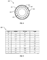
- Swashplate system 107 has been successfully tested and Figure 5 shows a table 501 comprising data taken during the testing.
- alternator system 109 creates approximately 26.68 volts at 68.8 watts (10 ohm load) at 100% rotor RPM. It should be appreciated that swashplate system 107 could easily be modified to produce a different electrical outcome by changing alternator subsystem 109, for example, providing more or less magnets, coils, and/or adding additional circuitry such as transformers.
- Swashplate system 601 is substantially similar in function to swashplate system 107. It should be understood that the features of swashplate system 107 could easily be incorporated in swashplate system 601; and likewise, the features of swashplate system 601 could interchangeable be incorporated in swashplate system 107.
- Swashplate system 601 comprises one or more of an inner ring 603 and an outer ring 605. It should be understood that outer ring 605 is adapted to rotate about rotary shaft 607, while inner ring 603 remains stationary about shaft 607. In the exemplary embodiment, the coils and magnets are carried by the rings in lieu of positioning an alternator subsystem thereabove, as shown in the foregoing figures and described above in detail with reference to the preferred embodiment.
- Inner ring 603 includes a portion 609 substantially similar to form and function to portion 307 of swashplate system 107. Portion 609 rigidly attaches to a support structure 611, thus holding support structure 611 in a relatively fixed position. Inner ring 603 is further provided with one or more magnets 613, either partially or fully disposed therein; and likewise, structure 611 is provided with one or more magnets 615 also either partially or fully disposed therein. Like swashplate system 107, the magnets of swashplate 601 are oriented and positioned to create a magnetic field for a coil to pass therethrough. Outer ring 605 comprises one or more coils 617 preferably extending through the thickness of outer ring 605. It should be understood that coils 617 are substantially similar in function to coils 317.
- the aircraft engine (not shown) rotates a rotor shaft 607, which in turn rotates the rotors.
- One or more driver links operably associated with the rotors rotate outer ring 605, which in turn rotates coils 617.
- An electrical voltage is created as coils 617 rotate within the magnetic field.
- the electrical voltage is channeled through wire 619 to an optional rectifier 621.
- Rectifier 621 conditions and rectifies the electrical voltage created by the magnets and coil, which in turn is channeled to electrical subsystem 111 via wire 623.
- Box 703 depicts the first step, which includes providing a swashplate having a rotating outer ring and a non-rotating inner ring.
- creating a magnetic field by providing a first magnet and an opposing second magnet, wherein the magnets are supported by the non-rotating inner ring, as depicted in box 705.
- an electrical current is created by passing a coil of wire through the magnetic field, wherein the coil of wire is supported by the outer ring, as depicted in box 707.
- the next step includes rectifying the electric current with a rectifier, as depicted in box 709.
- the last step includes channeling the electric current to an electrical subsystem via a conductor, i.e., a wire, as depicted in box 711.
Landscapes
- Engineering & Computer Science (AREA)
- Aviation & Aerospace Engineering (AREA)
- Mechanical Engineering (AREA)
- Synchronous Machinery (AREA)
- Connection Of Motors, Electrical Generators, Mechanical Devices, And The Like (AREA)
Claims (12)
- Drehflügelflugzeug-Taumelscheibensystem (107), aufweisend:eine Taumelscheibe mit:einem äußeren, rotierenden Ring (203);einem inneren, nicht-rotierenden Ring (201) mit einer Oberseite; undein Drehstromgenerator-Teilsystem, das von der Taumelscheibe getragen wird, wobei das Teilsystem aufweist:ein erstes nicht-rotierendes Magnetelement (301) mit einem ersten Magneten (313), wobei das erste nicht-rotierende Magnetelement wirkmäßig mit dem inneren, nicht-rotierenden Ring (201) der Taumelscheibe verbunden ist;ein zweites nicht-rotierendes Magnetelement (303) mit einem zweiten Magneten (315), wobei das zweite nicht-rotierende Magnetelement (303) wirkmäßig mit dem inneren nicht-rotierenden Ring (201) der Taumelscheibe verbunden ist; undein Wicklungselement (305) mit einer Drahtspule (317), wobei das Wicklungselement wirkmäßig mit dem äußeren rotierenden Ring (203) verbunden ist, wobei das Wicklungselement (305) so gestaltet ist, dass es zwischen dem ersten nicht-rotierenden Element (301) und dem zweiten nicht-rotierenden Element (303) hindurch verläuft;wobei der erste Magnet und der zweite Magnet selektiv so positioniert sind, dass zwischen ihnen ein Magnetfeld erzeugt wird; undwobei die Drahtspule (317), während der Ring (203) rotiert, durch das Magnetfeld hindurch geht, wodurch wiederum ein elektrischer Strom innerhalb der Drahtspule erzeugt wird.
- Taumelscheibensystem (107) nach Anspruch 1, ferner aufweisend:einen Gleichrichter (323), der von dem Wicklungselement (305) getragen wird;wobei der Gleichrichter (323) dafür ausgelegt ist, den elektrischen Strom gleichzurichten.
- Taumelscheibensystem (107) nach Anspruch 1, ferner aufweisend:eine Lagerführung (307), die wirkmäßig mit dem inneren, nicht-rotierenden Ring (201) verbunden ist;wobei das erste nicht-rotierende Magnetelement (301) und das zweite Magnetelement (303) über eine Befestigungseinrichtung an der Lagerführung festgelegt sind.
- Taumelscheibensystem (107) nach Anspruch 1, ferner aufweisend:eine Metallplatte (407), die an einer Oberfläche des ersten nicht-rotierenden Magnetelements (301) befestigt ist und zwischen der Oberfläche des ersten nicht-rotierenden Magnetelements (301) und einer Oberfläche des ersten Magneten (313) angeordnet ist.
- Taumelscheibensystem (107) nach Anspruch 1, wobei das erste nicht-rotierende Magnetelement (301) aufweist:eine Basis (401) mit einer Oberfläche;wobei die Oberfläche der Basis (401) relativ parallel zur Oberseite der Oberfläche des inneren nicht-rotierenden Rings (201) ausgerichtet ist.
- Taumelscheibensystem (107) nach Anspruch 5, wobei das erste nicht-rotierende Magnetelement (301) ferner aufweist:einen äußeren Ring (403), der von der Oberfläche der Basis (401) vorsteht; undeine Innenstruktur (405), die von der Oberfläche der Basis (401) vorsteht;wobei der äußere Ring (403) und die Innenstruktur (405) den Magneten sicher in einer relativ festgelegten Position tragen.
- Taumelscheibensystem (107) nach Anspruch 1, ferner aufweisend:ein elektrisches Teilsystem (111), das leitend mit der Drahtspule verbunden ist;wobei das Drehstromgenerator-Teilsystem, während sich der äußere Ring dreht, elektrischen Strom zum elektrischen Teilsystem liefert.
- Taumelscheibensystem (107) nach Anspruch 7, wobei das elektrische Teilsystem (111) ein Sensor ist, der wirkmäßig mit einem Rotorsystem verbunden ist.
- Taumelscheibensystem (107) nach Anspruch 7, wobei das elektrische Teilsystem (111) ein Licht ist, das wirkmäßig mit einem Rotorsystem verbunden ist.
- Verfahren (701) zum Erzeugen eines elektrischen Stroms mit einem Taumelscheibensystem, wobei das Taumelscheibensystem einen äußeren rotierenden Ring und einen inneren rotierenden Ring aufweist und wobei das Verfahren umfasst:Bereitstellen (703) des Drehflügelflugzeug-Taumelscheibensystems nach Anspruch 1;Erzeugen (705) eines Magnetfelds mit einem ersten Magneten und einem zweiten Magneten, die wirkmäßig mit dem nicht-rotierenden Ring verbunden sind;Bereitstellen einer Drahtspule, die wirkmäßig mit dem äußeren rotierenden Ring verbunden ist;Rotierenlassen des rotierenden Rings; undErzeugen (707) des elektrischen Stroms innerhalb der Drahtspule durch Führen der Drahtspule durch den ersten Magneten und den zweiten Magneten, die das Magnetfeld erzeugen, während der rotierende Ring rotiert.
- Verfahren nach Anspruch 10, ferner umfassend:Gleichrichten (709) des elektrischen Stroms mit einem Gleichrichter.
- Verfahren nach Anspruch 10, ferner umfassend:Leiten (711) des elektrischen Stroms zu einem elektrischen System, das leitungstechnisch mit der Drahtspule verbunden ist.
Applications Claiming Priority (2)
| Application Number | Priority Date | Filing Date | Title |
|---|---|---|---|
| US31664510P | 2010-03-23 | 2010-03-23 | |
| PCT/US2011/029134 WO2011119458A1 (en) | 2010-03-23 | 2011-03-21 | Swashplate-mounted permanent magnet alternator |
Publications (3)
| Publication Number | Publication Date |
|---|---|
| EP2550199A1 EP2550199A1 (de) | 2013-01-30 |
| EP2550199A4 EP2550199A4 (de) | 2013-07-24 |
| EP2550199B1 true EP2550199B1 (de) | 2014-03-12 |
Family
ID=44673544
Family Applications (1)
| Application Number | Title | Priority Date | Filing Date |
|---|---|---|---|
| EP20110759964 Not-in-force EP2550199B1 (de) | 2010-03-23 | 2011-03-21 | An einer taumelscheibe montierter permanentmagnet-generator |
Country Status (5)
| Country | Link |
|---|---|
| US (1) | US9024505B2 (de) |
| EP (1) | EP2550199B1 (de) |
| CN (1) | CN102811905B (de) |
| CA (1) | CA2792877C (de) |
| WO (1) | WO2011119458A1 (de) |
Families Citing this family (11)
| Publication number | Priority date | Publication date | Assignee | Title |
|---|---|---|---|---|
| EP2629407B1 (de) | 2012-02-17 | 2014-12-24 | Bell Helicopter Textron Inc. | Elektrischer Generator einer rotierenden Struktur |
| US8878374B2 (en) * | 2013-02-13 | 2014-11-04 | Bell Helicopter Textron Inc. | Brushless alternator for helicopter transmission install |
| US9296471B2 (en) * | 2013-10-06 | 2016-03-29 | The Boeing Company | Swing wing tip system, assembly and method with dual load path structure |
| DE102016212090A1 (de) | 2016-07-04 | 2018-01-04 | Airbus Defence and Space GmbH | Elektrische Energieerzeugungsvorrichtung für ein Luftfahrzeug sowie Verfahren zur Erzeugung elektrischer Energie in einem Luftfahrzeug |
| EP3284672B1 (de) | 2016-08-17 | 2019-06-26 | Airbus Defence and Space GmbH | Taumelscheibensystem und rotorsystem für einen helikopter |
| EP3342707B1 (de) * | 2016-12-30 | 2019-03-06 | Leonardo S.P.A. | Schwebeflugfähiges luftfahrzeug mit hauptrotor |
| EP3342706B1 (de) | 2016-12-30 | 2019-03-06 | Leonardo S.P.A. | Rotor für ein zum schwebeflug fähiges luftfahrzeug und zugehöriges verfahren |
| EP3342705B1 (de) * | 2016-12-30 | 2019-07-24 | Leonardo S.P.A. | Rotor für ein schwebeflugfähiges luftfahrzeug |
| US10994840B1 (en) | 2017-08-16 | 2021-05-04 | United States Of America As Represented By The Secretary Of The Air Force | Thrust vectoring control of a cyclorotor |
| EP4039587A1 (de) | 2021-02-03 | 2022-08-10 | AIRBUS HELICOPTERS DEUTSCHLAND GmbH | Taumelscheibenanordnung mit integriertem elektromotor |
| CN115014489B (zh) * | 2022-05-18 | 2024-03-19 | 杭州沛澜航空科技有限公司 | 无人直升机飞行重量测量方法及装置 |
Family Cites Families (18)
| Publication number | Priority date | Publication date | Assignee | Title |
|---|---|---|---|---|
| US4066890A (en) | 1976-09-24 | 1978-01-03 | The United States Of America As Represented By The Secretary Of The Army | Rotor tip light control |
| US4188556A (en) * | 1977-07-18 | 1980-02-12 | Acr Electronics, Inc. | Electro-mechanical machine |
| GB2090214B (en) * | 1980-08-13 | 1984-09-12 | Mckrill Nigel Howard | Controlling helicopter rotors |
| US5015187A (en) | 1990-02-28 | 1991-05-14 | Byron Hatfield | Helicopter remote control system |
| JP3623269B2 (ja) * | 1994-04-15 | 2005-02-23 | コールモージェン・コーポレーション | アキシャル・エアギャップ・モータ |
| US6048172A (en) | 1998-03-06 | 2000-04-11 | International Technologies (Lasers) Ltd. | Autonomous helicopter blade end lighting device |
| US6664689B2 (en) * | 2001-08-06 | 2003-12-16 | Mitchell Rose | Ring-shaped motor core with toroidally-wound coils |
| JP2003106250A (ja) | 2001-09-28 | 2003-04-09 | Eisuke Fujimoto | 学習用風力発電機 |
| BE1014724A6 (nl) * | 2002-03-25 | 2004-03-02 | Rostyne Alexander Van De | Inrichting voor de besturing van een helikopter. |
| US20050046195A1 (en) | 2003-08-28 | 2005-03-03 | Kousoulis Theodore P. | Motor vehicle with wind generator device |
| WO2005100154A1 (en) * | 2004-04-13 | 2005-10-27 | Wavefront Technology Pty Ltd | System for rotor head and rotor blade |
| GB0412085D0 (en) * | 2004-05-29 | 2004-06-30 | Univ Durham | Axial-flux, permanent magnet electrical machine |
| TWM299219U (en) * | 2005-12-02 | 2006-10-11 | Ming-Huang Lin | Improved electricity generator structure |
| US7218025B1 (en) | 2005-05-20 | 2007-05-15 | Contiempo Energy, Llc | Rotational magnetic electrical generating device |
| US7854590B2 (en) * | 2007-03-12 | 2010-12-21 | Bell Helicopter Textron Inc. | Rotor blade visual lights |
| EP2003054B1 (de) | 2007-06-15 | 2009-12-16 | Saab Ab | Vorrichtung zur Stromversorgung |
| US8178992B1 (en) * | 2010-11-23 | 2012-05-15 | Moshe Meller | Axial flux alternator with air gap maintaining arrangement |
| US8026626B1 (en) * | 2010-11-23 | 2011-09-27 | Moshe Meller | Axial flux alternator with air gap maintaining arrangement |
-
2011
- 2011-03-21 EP EP20110759964 patent/EP2550199B1/de not_active Not-in-force
- 2011-03-21 CA CA 2792877 patent/CA2792877C/en active Active
- 2011-03-21 CN CN201180014944.9A patent/CN102811905B/zh not_active Expired - Fee Related
- 2011-03-21 US US13/576,575 patent/US9024505B2/en active Active
- 2011-03-21 WO PCT/US2011/029134 patent/WO2011119458A1/en not_active Ceased
Also Published As
| Publication number | Publication date |
|---|---|
| EP2550199A4 (de) | 2013-07-24 |
| CA2792877C (en) | 2014-11-18 |
| CN102811905B (zh) | 2015-12-02 |
| WO2011119458A1 (en) | 2011-09-29 |
| US20120299428A1 (en) | 2012-11-29 |
| US9024505B2 (en) | 2015-05-05 |
| EP2550199A1 (de) | 2013-01-30 |
| CN102811905A (zh) | 2012-12-05 |
| CA2792877A1 (en) | 2011-09-29 |
Similar Documents
| Publication | Publication Date | Title |
|---|---|---|
| EP2550199B1 (de) | An einer taumelscheibe montierter permanentmagnet-generator | |
| EP2610176B1 (de) | Elektrischantrieb eines Heckrotors eines Hubschraubers | |
| CN112550730B (zh) | 用于螺旋桨发动机的电动马达 | |
| US10150567B2 (en) | Rotor systems for rotorcraft | |
| CN102395781B (zh) | 风能设备和用于调节转子叶片的驱动装置 | |
| EP3046232A1 (de) | Einteiliger endwicklungsträger mit integriertem schmiermittelverteiler | |
| CN103108803B (zh) | 直升飞机的尾桨的驱动装置 | |
| EP2836704B1 (de) | Windturbine mit vertikaler achse | |
| EP2432683B1 (de) | Träger einer propellereinheit für ein schiff | |
| RU2566590C2 (ru) | Электроснабжение для устройств, поддерживаемых ротором авиационного двигателя | |
| US20130127284A1 (en) | Aircraft | |
| US20200130824A1 (en) | Device for directly controlling a blade by means of an electromechanical actuator | |
| KR102806115B1 (ko) | 역회전 차동 전기 모터 어셈블리 | |
| US20180323737A1 (en) | Scalable electric generator | |
| US7453180B2 (en) | Rotary disk energy storage and pulse power supply | |
| CA2794077C (en) | Electrical powered tail rotor of a helicopter | |
| US10075035B2 (en) | Segmented dual radial gap brushless PMDC motor/generator | |
| CN114394243A (zh) | 一种太阳能无人机磁悬浮推进系统 | |
| CN121269100B (zh) | 螺旋桨除冰装置、除冰控制方法以及飞行器 | |
| US20220289369A1 (en) | Swashplate assembly with integrated electric motor | |
| US20210152053A1 (en) | Electric propellor drive and vehicle using the same | |
| US11691745B1 (en) | Systems and methods for locking an electric propulsion system | |
| WO2025125830A1 (en) | An electromagnetic propulsion system for aerial vehicles | |
| CN121395737A (zh) | 一种无轴盘式二维磁环磁约束无刷电机 | |
| CN119524952A (zh) | 一种磁驱双齿辊破碎机及其控制方法 |
Legal Events
| Date | Code | Title | Description |
|---|---|---|---|
| PUAI | Public reference made under article 153(3) epc to a published international application that has entered the european phase |
Free format text: ORIGINAL CODE: 0009012 |
|
| 17P | Request for examination filed |
Effective date: 20120906 |
|
| AK | Designated contracting states |
Kind code of ref document: A1 Designated state(s): AL AT BE BG CH CY CZ DE DK EE ES FI FR GB GR HR HU IE IS IT LI LT LU LV MC MK MT NL NO PL PT RO RS SE SI SK SM TR |
|
| RIN1 | Information on inventor provided before grant (corrected) |
Inventor name: MAST, JAMES Inventor name: BAIS, CHRISTOS Inventor name: DOYLE, JORDAN |
|
| DAX | Request for extension of the european patent (deleted) | ||
| A4 | Supplementary search report drawn up and despatched |
Effective date: 20130620 |
|
| RIC1 | Information provided on ipc code assigned before grant |
Ipc: B64C 27/605 20060101AFI20130614BHEP Ipc: B64D 41/00 20060101ALI20130614BHEP |
|
| GRAP | Despatch of communication of intention to grant a patent |
Free format text: ORIGINAL CODE: EPIDOSNIGR1 |
|
| INTG | Intention to grant announced |
Effective date: 20131112 |
|
| GRAS | Grant fee paid |
Free format text: ORIGINAL CODE: EPIDOSNIGR3 |
|
| GRAA | (expected) grant |
Free format text: ORIGINAL CODE: 0009210 |
|
| AK | Designated contracting states |
Kind code of ref document: B1 Designated state(s): AL AT BE BG CH CY CZ DE DK EE ES FI FR GB GR HR HU IE IS IT LI LT LU LV MC MK MT NL NO PL PT RO RS SE SI SK SM TR |
|
| REG | Reference to a national code |
Ref country code: GB Ref legal event code: FG4D |
|
| REG | Reference to a national code |
Ref country code: CH Ref legal event code: EP |
|
| REG | Reference to a national code |
Ref country code: AT Ref legal event code: REF Ref document number: 656106 Country of ref document: AT Kind code of ref document: T Effective date: 20140315 |
|
| REG | Reference to a national code |
Ref country code: IE Ref legal event code: FG4D |
|
| REG | Reference to a national code |
Ref country code: DE Ref legal event code: R096 Ref document number: 602011005381 Country of ref document: DE Effective date: 20140424 |
|
| REG | Reference to a national code |
Ref country code: NL Ref legal event code: VDEP Effective date: 20140312 |
|
| PG25 | Lapsed in a contracting state [announced via postgrant information from national office to epo] |
Ref country code: LT Free format text: LAPSE BECAUSE OF FAILURE TO SUBMIT A TRANSLATION OF THE DESCRIPTION OR TO PAY THE FEE WITHIN THE PRESCRIBED TIME-LIMIT Effective date: 20140312 Ref country code: NO Free format text: LAPSE BECAUSE OF FAILURE TO SUBMIT A TRANSLATION OF THE DESCRIPTION OR TO PAY THE FEE WITHIN THE PRESCRIBED TIME-LIMIT Effective date: 20140612 |
|
| REG | Reference to a national code |
Ref country code: AT Ref legal event code: MK05 Ref document number: 656106 Country of ref document: AT Kind code of ref document: T Effective date: 20140312 |
|
| REG | Reference to a national code |
Ref country code: LT Ref legal event code: MG4D |
|
| PG25 | Lapsed in a contracting state [announced via postgrant information from national office to epo] |
Ref country code: FI Free format text: LAPSE BECAUSE OF FAILURE TO SUBMIT A TRANSLATION OF THE DESCRIPTION OR TO PAY THE FEE WITHIN THE PRESCRIBED TIME-LIMIT Effective date: 20140312 Ref country code: CY Free format text: LAPSE BECAUSE OF FAILURE TO SUBMIT A TRANSLATION OF THE DESCRIPTION OR TO PAY THE FEE WITHIN THE PRESCRIBED TIME-LIMIT Effective date: 20140312 Ref country code: SE Free format text: LAPSE BECAUSE OF FAILURE TO SUBMIT A TRANSLATION OF THE DESCRIPTION OR TO PAY THE FEE WITHIN THE PRESCRIBED TIME-LIMIT Effective date: 20140312 |
|
| PG25 | Lapsed in a contracting state [announced via postgrant information from national office to epo] |
Ref country code: HR Free format text: LAPSE BECAUSE OF FAILURE TO SUBMIT A TRANSLATION OF THE DESCRIPTION OR TO PAY THE FEE WITHIN THE PRESCRIBED TIME-LIMIT Effective date: 20140312 Ref country code: RS Free format text: LAPSE BECAUSE OF FAILURE TO SUBMIT A TRANSLATION OF THE DESCRIPTION OR TO PAY THE FEE WITHIN THE PRESCRIBED TIME-LIMIT Effective date: 20140312 Ref country code: LV Free format text: LAPSE BECAUSE OF FAILURE TO SUBMIT A TRANSLATION OF THE DESCRIPTION OR TO PAY THE FEE WITHIN THE PRESCRIBED TIME-LIMIT Effective date: 20140312 |
|
| PG25 | Lapsed in a contracting state [announced via postgrant information from national office to epo] |
Ref country code: RO Free format text: LAPSE BECAUSE OF FAILURE TO SUBMIT A TRANSLATION OF THE DESCRIPTION OR TO PAY THE FEE WITHIN THE PRESCRIBED TIME-LIMIT Effective date: 20140312 Ref country code: BE Free format text: LAPSE BECAUSE OF FAILURE TO SUBMIT A TRANSLATION OF THE DESCRIPTION OR TO PAY THE FEE WITHIN THE PRESCRIBED TIME-LIMIT Effective date: 20140312 Ref country code: BG Free format text: LAPSE BECAUSE OF FAILURE TO SUBMIT A TRANSLATION OF THE DESCRIPTION OR TO PAY THE FEE WITHIN THE PRESCRIBED TIME-LIMIT Effective date: 20140612 Ref country code: EE Free format text: LAPSE BECAUSE OF FAILURE TO SUBMIT A TRANSLATION OF THE DESCRIPTION OR TO PAY THE FEE WITHIN THE PRESCRIBED TIME-LIMIT Effective date: 20140312 Ref country code: CZ Free format text: LAPSE BECAUSE OF FAILURE TO SUBMIT A TRANSLATION OF THE DESCRIPTION OR TO PAY THE FEE WITHIN THE PRESCRIBED TIME-LIMIT Effective date: 20140312 Ref country code: IS Free format text: LAPSE BECAUSE OF FAILURE TO SUBMIT A TRANSLATION OF THE DESCRIPTION OR TO PAY THE FEE WITHIN THE PRESCRIBED TIME-LIMIT Effective date: 20140712 Ref country code: NL Free format text: LAPSE BECAUSE OF FAILURE TO SUBMIT A TRANSLATION OF THE DESCRIPTION OR TO PAY THE FEE WITHIN THE PRESCRIBED TIME-LIMIT Effective date: 20140312 |
|
| REG | Reference to a national code |
Ref country code: CH Ref legal event code: PL |
|
| PG25 | Lapsed in a contracting state [announced via postgrant information from national office to epo] |
Ref country code: SK Free format text: LAPSE BECAUSE OF FAILURE TO SUBMIT A TRANSLATION OF THE DESCRIPTION OR TO PAY THE FEE WITHIN THE PRESCRIBED TIME-LIMIT Effective date: 20140312 Ref country code: PL Free format text: LAPSE BECAUSE OF FAILURE TO SUBMIT A TRANSLATION OF THE DESCRIPTION OR TO PAY THE FEE WITHIN THE PRESCRIBED TIME-LIMIT Effective date: 20140312 Ref country code: ES Free format text: LAPSE BECAUSE OF FAILURE TO SUBMIT A TRANSLATION OF THE DESCRIPTION OR TO PAY THE FEE WITHIN THE PRESCRIBED TIME-LIMIT Effective date: 20140312 Ref country code: AT Free format text: LAPSE BECAUSE OF FAILURE TO SUBMIT A TRANSLATION OF THE DESCRIPTION OR TO PAY THE FEE WITHIN THE PRESCRIBED TIME-LIMIT Effective date: 20140312 |
|
| REG | Reference to a national code |
Ref country code: DE Ref legal event code: R097 Ref document number: 602011005381 Country of ref document: DE |
|
| PG25 | Lapsed in a contracting state [announced via postgrant information from national office to epo] |
Ref country code: PT Free format text: LAPSE BECAUSE OF FAILURE TO SUBMIT A TRANSLATION OF THE DESCRIPTION OR TO PAY THE FEE WITHIN THE PRESCRIBED TIME-LIMIT Effective date: 20140714 |
|
| REG | Reference to a national code |
Ref country code: IE Ref legal event code: MM4A |
|
| PLBE | No opposition filed within time limit |
Free format text: ORIGINAL CODE: 0009261 |
|
| STAA | Information on the status of an ep patent application or granted ep patent |
Free format text: STATUS: NO OPPOSITION FILED WITHIN TIME LIMIT |
|
| PG25 | Lapsed in a contracting state [announced via postgrant information from national office to epo] |
Ref country code: CH Free format text: LAPSE BECAUSE OF NON-PAYMENT OF DUE FEES Effective date: 20140331 Ref country code: MC Free format text: LAPSE BECAUSE OF FAILURE TO SUBMIT A TRANSLATION OF THE DESCRIPTION OR TO PAY THE FEE WITHIN THE PRESCRIBED TIME-LIMIT Effective date: 20140312 Ref country code: DK Free format text: LAPSE BECAUSE OF FAILURE TO SUBMIT A TRANSLATION OF THE DESCRIPTION OR TO PAY THE FEE WITHIN THE PRESCRIBED TIME-LIMIT Effective date: 20140312 Ref country code: LI Free format text: LAPSE BECAUSE OF NON-PAYMENT OF DUE FEES Effective date: 20140331 Ref country code: IE Free format text: LAPSE BECAUSE OF NON-PAYMENT OF DUE FEES Effective date: 20140321 |
|
| 26N | No opposition filed |
Effective date: 20141215 |
|
| PG25 | Lapsed in a contracting state [announced via postgrant information from national office to epo] |
Ref country code: RS Free format text: LAPSE BECAUSE OF FAILURE TO SUBMIT A TRANSLATION OF THE DESCRIPTION OR TO PAY THE FEE WITHIN THE PRESCRIBED TIME-LIMIT Effective date: 20140903 |
|
| REG | Reference to a national code |
Ref country code: DE Ref legal event code: R097 Ref document number: 602011005381 Country of ref document: DE Effective date: 20141215 |
|
| PG25 | Lapsed in a contracting state [announced via postgrant information from national office to epo] |
Ref country code: SI Free format text: LAPSE BECAUSE OF FAILURE TO SUBMIT A TRANSLATION OF THE DESCRIPTION OR TO PAY THE FEE WITHIN THE PRESCRIBED TIME-LIMIT Effective date: 20140312 |
|
| PG25 | Lapsed in a contracting state [announced via postgrant information from national office to epo] |
Ref country code: MT Free format text: LAPSE BECAUSE OF FAILURE TO SUBMIT A TRANSLATION OF THE DESCRIPTION OR TO PAY THE FEE WITHIN THE PRESCRIBED TIME-LIMIT Effective date: 20140312 |
|
| REG | Reference to a national code |
Ref country code: FR Ref legal event code: PLFP Year of fee payment: 6 |
|
| PG25 | Lapsed in a contracting state [announced via postgrant information from national office to epo] |
Ref country code: SM Free format text: LAPSE BECAUSE OF FAILURE TO SUBMIT A TRANSLATION OF THE DESCRIPTION OR TO PAY THE FEE WITHIN THE PRESCRIBED TIME-LIMIT Effective date: 20140312 |
|
| PG25 | Lapsed in a contracting state [announced via postgrant information from national office to epo] |
Ref country code: GR Free format text: LAPSE BECAUSE OF FAILURE TO SUBMIT A TRANSLATION OF THE DESCRIPTION OR TO PAY THE FEE WITHIN THE PRESCRIBED TIME-LIMIT Effective date: 20140613 |
|
| PG25 | Lapsed in a contracting state [announced via postgrant information from national office to epo] |
Ref country code: TR Free format text: LAPSE BECAUSE OF FAILURE TO SUBMIT A TRANSLATION OF THE DESCRIPTION OR TO PAY THE FEE WITHIN THE PRESCRIBED TIME-LIMIT Effective date: 20140312 Ref country code: LU Free format text: LAPSE BECAUSE OF NON-PAYMENT OF DUE FEES Effective date: 20140321 Ref country code: HU Free format text: LAPSE BECAUSE OF FAILURE TO SUBMIT A TRANSLATION OF THE DESCRIPTION OR TO PAY THE FEE WITHIN THE PRESCRIBED TIME-LIMIT; INVALID AB INITIO Effective date: 20110321 |
|
| REG | Reference to a national code |
Ref country code: FR Ref legal event code: PLFP Year of fee payment: 7 |
|
| REG | Reference to a national code |
Ref country code: FR Ref legal event code: PLFP Year of fee payment: 8 |
|
| PG25 | Lapsed in a contracting state [announced via postgrant information from national office to epo] |
Ref country code: MK Free format text: LAPSE BECAUSE OF FAILURE TO SUBMIT A TRANSLATION OF THE DESCRIPTION OR TO PAY THE FEE WITHIN THE PRESCRIBED TIME-LIMIT Effective date: 20140312 |
|
| PG25 | Lapsed in a contracting state [announced via postgrant information from national office to epo] |
Ref country code: AL Free format text: LAPSE BECAUSE OF FAILURE TO SUBMIT A TRANSLATION OF THE DESCRIPTION OR TO PAY THE FEE WITHIN THE PRESCRIBED TIME-LIMIT Effective date: 20140312 |
|
| PGFP | Annual fee paid to national office [announced via postgrant information from national office to epo] |
Ref country code: FR Payment date: 20230327 Year of fee payment: 13 |
|
| PGFP | Annual fee paid to national office [announced via postgrant information from national office to epo] |
Ref country code: IT Payment date: 20230321 Year of fee payment: 13 Ref country code: GB Payment date: 20230327 Year of fee payment: 13 Ref country code: DE Payment date: 20230329 Year of fee payment: 13 |
|
| P01 | Opt-out of the competence of the unified patent court (upc) registered |
Effective date: 20230602 |
|
| REG | Reference to a national code |
Ref country code: DE Ref legal event code: R119 Ref document number: 602011005381 Country of ref document: DE |
|
| GBPC | Gb: european patent ceased through non-payment of renewal fee |
Effective date: 20240321 |
|
| PG25 | Lapsed in a contracting state [announced via postgrant information from national office to epo] |
Ref country code: DE Free format text: LAPSE BECAUSE OF NON-PAYMENT OF DUE FEES Effective date: 20241001 |
|
| PG25 | Lapsed in a contracting state [announced via postgrant information from national office to epo] |
Ref country code: GB Free format text: LAPSE BECAUSE OF NON-PAYMENT OF DUE FEES Effective date: 20240321 |
|
| PG25 | Lapsed in a contracting state [announced via postgrant information from national office to epo] |
Ref country code: FR Free format text: LAPSE BECAUSE OF NON-PAYMENT OF DUE FEES Effective date: 20240331 |
|
| PG25 | Lapsed in a contracting state [announced via postgrant information from national office to epo] |
Ref country code: GB Free format text: LAPSE BECAUSE OF NON-PAYMENT OF DUE FEES Effective date: 20240321 Ref country code: FR Free format text: LAPSE BECAUSE OF NON-PAYMENT OF DUE FEES Effective date: 20240331 Ref country code: DE Free format text: LAPSE BECAUSE OF NON-PAYMENT OF DUE FEES Effective date: 20241001 |
|
| PG25 | Lapsed in a contracting state [announced via postgrant information from national office to epo] |
Ref country code: IT Free format text: LAPSE BECAUSE OF NON-PAYMENT OF DUE FEES Effective date: 20240321 |