EP2549286B1 - Navigationssystem für die Erkundung und / oder Überwachung unbekannter und / oder schwieriger Umgebungen - Google Patents
Navigationssystem für die Erkundung und / oder Überwachung unbekannter und / oder schwieriger Umgebungen Download PDFInfo
- Publication number
- EP2549286B1 EP2549286B1 EP12176982.2A EP12176982A EP2549286B1 EP 2549286 B1 EP2549286 B1 EP 2549286B1 EP 12176982 A EP12176982 A EP 12176982A EP 2549286 B1 EP2549286 B1 EP 2549286B1
- Authority
- EP
- European Patent Office
- Prior art keywords
- node
- nodes
- hierarchical level
- hierarchical
- radio interface
- Prior art date
- Legal status (The legal status is an assumption and is not a legal conclusion. Google has not performed a legal analysis and makes no representation as to the accuracy of the status listed.)
- Active
Links
Images


Classifications
-
- G—PHYSICS
- G01—MEASURING; TESTING
- G01S—RADIO DIRECTION-FINDING; RADIO NAVIGATION; DETERMINING DISTANCE OR VELOCITY BY USE OF RADIO WAVES; LOCATING OR PRESENCE-DETECTING BY USE OF THE REFLECTION OR RERADIATION OF RADIO WAVES; ANALOGOUS ARRANGEMENTS USING OTHER WAVES
- G01S5/00—Position-fixing by co-ordinating two or more direction or position line determinations; Position-fixing by co-ordinating two or more distance determinations
- G01S5/02—Position-fixing by co-ordinating two or more direction or position line determinations; Position-fixing by co-ordinating two or more distance determinations using radio waves
- G01S5/0284—Relative positioning
- G01S5/0289—Relative positioning of multiple transceivers, e.g. in ad hoc networks
Definitions
- the present invention relates to a navigation system for exploring and/or monitoring unknown and/or difficult (or inaccessible) environments, such as:
- unmanned or remotely-controlled vehicles for example robots, which are configured to move in said environments and to acquire data on the surrounding environment during movement, are currently used.
- unmanned ground vehicles called rovers are used.
- a robot/rover is often assigned objectives to be reached, which are expressed in terms of position. For example, a robot/rover can receive commands that tell it to reach a specific position, to explore a specific area, to return in proximity to a predefined landmark, etc.
- estimation of the position of a robot/rover and the accuracy, or reliability, of this estimation are linked to long-range navigation for the construction of global maps of the environment explored/monitored, for finding the trajectories or paths that the robot/rover must follow and for enabling mission supervision.
- the spatial consistency of the maps generated is essential for efficient and robust operation of the robot/rover and it is the very knowledge of the position of the robot/rover that guarantees this consistency.
- GNSSs Global Navigation Satellite Systems
- Galileo Galileo
- GPS Global Navigation Satellite Systems
- GLONASS Global Navigation Satellite Systems
- a constellation of artificial satellites of GNSS type that enable localization of a rover.
- motion estimation methods can be used to measure acceleration, speed and displacements between two known positions integrating raw data (odometry, inertial navigation, visual motion estimation, etc.).
- the error on the position estimation obtained increases over time, regardless of the type of movement.
- position refinement methods enable the position of a robot or rover to be estimated (or an initial position estimation to be corrected) using environmental models.
- These models can describe environmental features useful for localization of the robot/rover, for example landmarks, and/or represent with continuity the geometry of the terrain, such as digital elevation models (DEMs).
- DEMs digital elevation models
- absolute localization methods aim at localizing a robot or rover with respect to an initial global model of the environment that can, for example, be constructed on the basis of images acquired by satellites or of digital models of the terrain determined on the basis of said images.
- Mobile Ad-hoc NETworks adapting to dynamically changing mobile ad-hoc network environments and providing location-aware capability
- US 2007/115895 A1 discloses a hybrid MANET and a method of operating the same, including a mobile network node and a plurality of static network nodes randomly distributed over a coverage area with a predetermined density.
- the static network nodes form a static infrastructure backbone of the hybrid MANET.
- Position information of the static network nodes either through position awareness or triangulation with reference to other static nodes, enhances the network function.
- the method tracks mobile node position with a minimum of overhead because of the fixed infrastructure of static nodes.
- the infrastructure can self-heal by placing excess static nodes in a hibernating state, and activating those in response to the failure of a nearby static node.
- the Applicant has conducted an in-depth study on the navigation systems currently used in exploration/monitoring missions in unknown/difficult environments and, at the end of this study, felt the need to develop an innovative navigation system for unknown and/or difficult environments that operates more reliably and is more robust than those currently known and that consequently can be advantageously used for the navigation of a robot/rover in these environments, for exploring these environments and for monitoring these environments.
- the object of the present invention is that of providing a navigation system of the above-stated type.
- the present invention concerns a navigation system for exploring and/or monitoring unknown and/or difficult environments, comprising:
- the primary node and the secondary nodes are configured to form a hierarchical communication and localization network in which:
- the unmanned vehicle comprises a vehicle control unit that includes a respective predefined radiocommunication interface and a respective ultra-wideband radio interface and that is configured to receive data from the mission control module using the respective predefined radiocommunication interface.
- the mission control module comprises a respective predefined radiocommunication interface and is configured to send mission data concerning the exploration and/or monitoring mission and navigation data concerning the local reference coordinate system and the overall integrity state of the hierarchical communication and localization network to the vehicle control unit using the respective predefined radiocommunication interface.
- vehicle control unit is further configured to:
- a preferred embodiment of the present invention concerns a navigation system for a rover operating on an extraterrestrial planet.
- said navigation system comprises:
- the operation of the navigation system according to the preferred embodiment of the present invention will be described in detail presenting the various functionalities of each component of said system.
- the various functionalities of each component of the navigation system will often be described, for the sake of description simplicity, as implemented by the component as a whole, for example hereinafter the functionalities implemented by the lander as a whole and the functionalities implemented by the rover as a whole will often be described.
- the lander can advantageously comprise:
- each rover in order to implement the respective functionalities, can advantageously comprise:
- the lander and the wireless devices are configured to form a hierarchical communication and localization network that operates as localization system for the rover.
- the lander calculates, as will be explained in detail hereinafter, a local reference system on the basis of the distance, or ranging, measurements that each wireless device calculates with respect to the wireless devices with which said wireless device is able to establish a wireless communication through the short-range radio interface based on UWB technology (cooperative positioning).
- the rover is considered as a "dynamic node" of the hierarchical communication and localization network and can recover its position in the local reference system both by calculating its position autonomously and by receiving information and data from the data processing unit of the lander.
- the lander operates as primary node of the hierarchical communication and localization network and represents the origin of the local reference system.
- the rover communicates, through the short-range radio interface based on UWB technology, with the wireless devices in order to determine its position in the local reference system.
- the position of the rover is determined in the local reference system and, if the lander is referenced on a global reference system, for example a planetary reference system, then the position of the rover can also be calculated in the global reference system.
- the communication protocol used by the wireless devices makes it possible to:
- the communication protocol used by the wireless devices enables each wireless device to communicate with the lander through a routing mechanism that uses intermediate wireless devices ("multi-hop" routing mechanism) in the case in which the lander is out of the direct communication range of the short-range radio interface based on UWB technology of said wireless device.
- the navigation system implements a centralized calculation concept in order to minimize the energy consumption of the wireless devices.
- the data processing unit of the lander carries out calculations that are more onerous in terms of calculation power required, such as:
- the data processing unit of the lander can advantageously also provide an auxiliary/supplementary calculation of the position of the rover on the basis of the signals that the rover receives from the wireless devices, for example in the case in which the rover requires to save energy or in the case in which the computational resources of the rover must be diverted to other tasks.
- the navigation system uses two different radio communication channels:
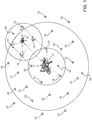
- Figure 1 schematically shows examples of radiocommunications based on the two above-stated radio channels.
- Figure 1 shows:
- some wireless devices 13 may also be outside the third radio coverage area 16, i.e. beyond the coverage limit provided by the second radio channel.
- This condition does not represent an anomaly as the navigation system is capable of using these wireless devices 13 both for normal operations (those that take place in the coverage range of the second radio channel), and as a security system for emergency conditions in the case in which the rover 12 is located outside the range of the second radio channel (for example, due to errors in the processing of commands or due to a decrease in the transmission power of the lander 11 and/or of the rover 12).
- the wireless devices are deployed on the surface of the extraterrestrial planet during the descent of the lander on the extraterrestrial planet.
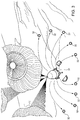
- Figure 2 shows, schematically and purely by way of example, entry of the lander into the atmosphere of the extraterrestrial planet, and descent and landing of the lander on the extraterrestrial planet.
- Figure 2 shows:
- the wireless devices are preferably released during the descent of the lander on the extraterrestrial planet at different heights in such a manner as to cover a ground area of the dimension necessary for the exploration mission of the rover.
- the ground area covered by the wireless devices is the operating area, or service area, wherein the navigation system provides its capacities to determine the position of the rover.
- the network of the wireless devices can advantageously be expanded through further wireless devices released by the rover during its movement on the surface of the extraterrestrial planet in order to extend and improve the coverage, performances and integrity of the localization and navigation service. Therefore, to summarize, deployment of the wireless devices, which determines the service area and the performances of the navigation system, can be implemented:
- Figure 3 shows, schematically and purely by way of example, the release of wireless devices during the descent of the lander on the extraterrestrial planet, in particular in a step of descent comprised between the second step 22 and the fourth step 24 shown in Figure 2 .
- Figure 3 shows:
- deployment of the wireless devices during the EDL steps determines the service area of the navigation system. Therefore, in carrying out this deployment it is important to take into account the geometric distribution of the wireless devices and their mutual distance on the surface of the extraterrestrial planet.
- the expected distance of the wireless devices from the vertical of the position of the lander during the EDL steps can advantageously be preliminarily determined during the mission planning step in order to define the service area of the navigation system and the density of the wireless devices.
- said wireless devices could advantageously be released during the EDL steps of the lander as follows:
- the lander After the wireless devices have been deployed on the surface of the extraterrestrial planet during the EDL steps of the lander and after the lander has landed and has terminated all the preliminary operations (for example after it has deployed the solar panels used to produce energy), the lander starts, autonomously or in response to one or more commands received remotely (for example from a control station on Earth or from a space station orbiting around the extraterrestrial planet), a initialization step aimed at defining the hierarchical communication and localization network formed by the lander and by the wireless devices.
- commands received remotely for example from a control station on Earth or from a space station orbiting around the extraterrestrial planet
- the generation and transmission of control messages in the hierarchical communication and localization network is based on a hierarchical system structured in several levels identified by a natural number comprised between 0 and MAX_LEVEL wherein the smaller the number, the greater the authority of the messages transmitted.
- the lander represents the level-0 node, while all the wireless devices, before initialization, are advantageously preconfigured to a level equal to MAX_LEVEL.
- the lander i.e. the level-0 node of the hierarchical communication and localization network, carries out a search of the wireless devices adjacent thereto on the first radio channel, i.e. on the radio channel based on UWB technology.
- adjacency is defined in terms of "radio visibility”.
- two nodes of the hierarchical communication and localization network are said to be adjacent if and only if a wireless communication based on the use of short-range UWB technology, i.e. based on the use of the first radio channel, can be established between them.
- the search for radio devices adjacent to the lander consists in the lander sending in broadcast an activation message (i.e. addressed to all).
- the wireless devices that are able to receive the activation message reply to the lander and start to carry out distance (i.e. ranging) measurements from the lander.
- These wireless devices help to determine level 1 of the hierarchical communication and localization network.
- the ranging measurements continue for a preset time, at the end of which the wireless devices whose distances comply with predetermined parameters of statistical stability of the ranging measurements are determined; these wireless devices become the level-1 nodes of the hierarchical communication and localization network.
- Figure 4 schematically shows an example of communication protocol that can be used according to a preferred embodiment of the present invention to activate and configure as level-1 node a wireless device adjacent to the lander.
- Figure 4 shows a temporal diagram of the messages exchanged on the first radio channel between the lander (indicated with 41) and a wireless device (indicated with 42) adjacent thereto.
- Figure 4 schematically shows:
- the wireless devices identified as level-1 nodes carry out ranging measurements with all the other active wireless devices (which in this step comprise only the lander and the level-1 wireless devices).
- the measurements thus carried out are sent to the lander which uses them to determine the geometry, i.e. the topology, of the local reference system.
- the lander uses them to determine the geometry, i.e. the topology, of the local reference system.
- the lander uses them to determine the geometry, i.e. the topology, of the local reference system.
- at least two active level-1 wireless devices are necessary, while to determine a local three-dimensional reference system a larger minimum number of measurements are required.
- the first step in determination of a local two-dimensional Cartesian reference system is the selection of a node (i.e. of a wireless device) that enables the axis of the abscissae, i.e. the x-axis, of the two-dimensional Cartesian reference system to be fixed.
- This x-axis is identified by the hypothetical segment that joins the lander and the wireless device selected.
- this node has the coordinates (d(L,k),0), where d(L,k) represents the distance from the lander L of the wireless device k selected to fix the x-axis.
- the axis of the ordinates, i.e. the y-axis, of the two-dimensional Cartesian reference system is also automatically determined.
- the selection criterion of the wireless device used to fix the x-axis of the local two-dimensional Cartesian reference system is based on the use of statistical information gathered during the initialization step of level 1 of the hierarchical communication and localization network.
- the node i.e. the wireless device
- the following parameters can be considered: the difference between the minimum and the maximum distance measured, and statistics of the first and of the second order (mean and variance) on the ranging measurements taken between the element (i.e. the wireless device) considered, the lander and all the other adjacent wireless devices.
- Another parameter that can be considered is the number of wireless devices adjacent to the node considered.
- the object of this evaluation is to select a node that guarantees the greatest stability in the measurements (minimization of propagation of measurement errors) and that is in communication with the largest possible number of other nodes. This information implicitly provides indications on the stability on the ground of the node and the quality of the signal (multipath, line of sight (LOS), etc.).
- the lander uses the measurements taken in the initialization step of level 1 to calculate the coordinates of the remaining nodes.
- the coordinates are calculated incrementally adding, one by one, the level-1 nodes to which coordinates have not yet been assigned in the local two-dimensional Cartesian reference system.
- the lander calculates the coordinates of the level-1 nodes on the basis of the coordinates of the level-1 nodes with coordinates that have already been determined and of the ranging measurements taken in the initialization step of level 1.
- the lander is the node with coordinates (0,0), i.e. it represents the origin of the local two-dimensional Cartesian reference system.
- Figure 5 schematically shows calculation of the coordinates of a generic level-1 node (i.e. wireless device) j on the basis of the coordinates of the lander L and of the node k selected to fix the x-axis of the local reference system, of the distance of the node k from the lander L calculated in the initialization step of level 1, of the distance of the node j from the lander L calculated in the initialization step of level 1 and of the distance of the node k from the node j calculated in the initialization step of level 1.
- a generic level-1 node i.e. wireless device
- Figure 5 shows:
- ⁇ arccos d L j 2 + d L k 2 ⁇ d j k 2 2 ⁇ d L k .
- the procedure to define the local reference system described above for the two-dimensional case can, as previously said, also be used to define a local three-dimensional reference system.
- at least three active level-1 wireless devices are necessary in order to determine a local three-dimensional reference system.
- the precision and reliability of calculation of the third dimension i.e. of the vertical coordinates, can be improved using a data fusion technique based on data supplied by sensors coupled to the wireless devices (and if necessary also to the lander), such as (in the case in which the extraterrestrial planet has an atmosphere and the atmospheric behaviour of said extraterrestrial planet is known) barometric altimeters, and/or through digital models of the terrain of the extraterrestrial planet obtained through radar acquisitions, satellite ranging systems, etc..
- the lander has defined the local reference system and calculated the coordinates of all the level-1 wireless devices, the same procedure is repeated for the subsequent levels, i.e. for the nodes that could not be reached by the lander during the first step.
- the level-1 nodes start the same procedure started by the lander, i.e. they transmit in broadcast an activation message.
- the primary difference is that the information collected is sent by the level-1 nodes to the lander, where it is processed.
- each level-1 node carries out ranging measurements with all the nodes adjacent thereto not yet activated (i.e. whose level identification number has not yet been assigned or is set to the maximum value MAX_LEVEL). The measurements taken are then transferred from the level-1 nodes to the lander which uses them to determine the nodes to be activated, which are, therefore, assigned the identification number of level 2.
- a ranging measurement session is carried out by the newly activated nodes, to which all the currently activated nodes reply, i.e., in this step, the level-2 and level-1 nodes.
- These measurements are sent by each level-2 wireless device, using a routing mechanism that involves at least one respective level-1 node, to the lander that uses them to determine the coordinates of the newly activated wireless devices.
- each communication device i.e. each node to which a respective level l has been assigned (with 1 ⁇ l ⁇ MAX_LEVEL)
- can communicate directly on the first radio channel i.e. on the radio channel based on UWB technology
- the wireless devices i.e. the nodes
- the level-1 nodes are in direct communication with the lander
- the level-2 nodes and those of the subsequent levels cannot communicate directly with the lander and, in order to reach it, they must therefore use a routing protocol that relies on other network nodes.
- a preferred solution to the problem of identification of the routing path from any one node toward the lander involves the use of the same incremental approach used for activation and initialization of the nodes of the hierarchical communication and localization network.
- the process is based on identification of at least one level l-1 reference node (where l indicates the level of the node for which communication with the lander is to be guaranteed) which operates as a gateway for communications with the lander.
- the reference node that acts as a gateway for communications with the lander is the lander itself.
- the level-1 nodes can act as a gateway to the lander for the level-2 nodes.
- the level-2 nodes can operate as a gateway to the lander for the level-3 nodes, and so forth.
- each level l-1 node therefore, is in direct or indirect communication with the lander.
- Each level l-1 node then repeats the activation procedure and sends an activation message in broadcast.
- the nodes in standby mode i.e. that have not yet initialized, that correctly decode the activation message save the address of the sender in a vector as potential gateway to be selected for routing the communication to the lander.
- the senders belonging to level l-1, have already completed the initialization procedure, and therefore they must be in direct or indirect communication with the lander, i.e., even if they are not in direct communication with the lander, they know a way of routing information to the lander.
- routing methods can advantageously be implemented in the hierarchical communication and localization network both alternatively to the method described above, and as back-up methods.
- the most suitable routing method can advantageously be selected as a function of specific parameters of the mission in which the navigation system is used (for example as a function of the density of the nodes, of the duty-cycle, of the frequency with which the system must update the local reference system, etc.).
- variants of known routing algorithms for wireless communication device networks can be considered.
- the system can advantageously solve problems of access to the radio channel typical of a UWB multi-hop network by assigning transmission codes, or, more in general, the access parameters to the physical channel, according to the launch step of the wireless device and/or its initialization.
- the state of the navigation system can be summarized as follows:
- the rover can determine a gateway table of its own if it requires to use the hierarchical communication and localization network to communicate with the lander, as its point of access to this network can be any one of the wireless devices adjacent to the rover in the position in which it is located at the time.
- each wireless device, active and operating constitutes a valid access point to the hierarchical communication and localization network. Therefore, the rover can communicate with the lander through the hierarchical communication and localization network using an adjacent wireless device as access point to this network.
- the rover moves inside the operating area and periodically carries out ranging measurements with the wireless devices adjacent thereto. Using these measurements together with the information on the topology of the hierarchical communication and localization network transmitted by the lander, the rover calculates its position inside the operating area with respect to the local reference system.
- the drive system of the rover must take into account the proximity information of the wireless devices to avoid colliding with them.
- a significant displacement of the position of the wireless devices could require calculation of a new local reference system. Therefore, the rover is advantageously configured to avoid colliding with the wireless devices (for example by stopping and/or recalculating the trajectory along which it is moving) on the basis of its position, of information on the topology of the hierarchical communication and localization network transmitted by the lander and of the ranging measurements carried out by said rover.
- the wireless devices are used intrinsically as radio beacons, i.e.
- the lander periodically activates a verification procedure of the state of integrity of the navigation system, in particular of the hierarchical communication and localization network, in such a manner as to:
- the information relating to the state of integrity of the navigation system is transmitted from the lander to the rover which can modify its behaviour as a function of said state of integrity (for example it can reduce speed, it can wait for more stable conditions to perform activities that require high reliability of the position information, etc.) up to the limit case in which the lander communicates to the rover the need to re-initialize the hierarchical communication and localization network. Therefore, the rover is advantageously configured to modify its operating behaviour (for example by stopping) if the state of integrity of the navigation system does not satisfy predetermined conditions.
- the navigation system is capable of providing positioning with accuracy below one metre and is configured also to implement monitoring and control functionalities.
- the impossibility of forecasting and counteracting any environmental variations (sand storms, tectonic activity, instability of the terrain) and any faults in the wireless devices (power supply anomalies due to contingent weather conditions, circuit errors, etc.) are compensated by modules for self-monitoring and determining the state of integrity of the navigation system, i.e. of the hierarchical communication and localization network.
- the integrity information is made available to the rovers so as to be used in combination with their "operating plans" (for example, some operating steps could require specific accuracy or reliability).
- the central mission control system can even decide to stop the rovers until the nominal operating conditions of the navigation system are restored.
- the navigation system provides this monitoring of the state of integrity through its primary functionality, i.e. through automatic calculation of the topology of the hierarchical communication and localization network and through determination of the local reference system.
- the local reference system represents the most important high level requirement for each navigation system.
- the first operating step established for the navigation system according to the preferred embodiment of the present invention is the determination of the local reference system and of the position of each wireless device in this local reference system.
- the local reference system depends on the position of each wireless device and, therefore, cannot be assumed as static.
- the greatest strength of the integrity system of the navigation system is the use of its primary functionality not only for preliminary initialization, but also as continuous service for the supply of differential information concerning the accuracy and validity of the local reference system. This information is disseminated to the wireless devices and to the rovers in order to enable them to perform and implement specific actions dependent on their specific state.
- the navigation system according to the preferred embodiment of the present invention a system with great flexibility and configurability.
- the autonomous mechanism for determining the topology of the hierarchical communication and localization network is low cost and represents a simple and direct manner of returning the whole system toward a steady state, thus enabling major fault recovery primarily re-using the operating functions.
- the number of wireless devices depends on the dimension of the operating area and on the UWB communication radius between two wireless devices and, naturally, also on the loading capacity of the lander.
- the UWB communication distance between two wireless devices depends on the usable transmission power and on the duration established for the mission.
- the ability of the navigation system to simultaneously transfer information and determine the position enables high flexibility in the definition of specialized instances of the system to cover a wide range of possible application scenarios. In any case, the functionalities and basic performances of the navigation system are guaranteed regardless of the specific specialization and adaptation to a specific mission.
- the primary functionalities and characteristics and some indicative performances of the navigation system are indicated in the following.
- the navigation system can advantageously be configured to perform a weighted calculation of the levels of integrity as a function of the mission priorities.
- the accuracy of the positioning in the plane is a function of the accuracy in determining the coordinates of the wireless devices, of the accuracy of the ranging measurements taken by the rovers, of the distance of the rover from the lander (the measurement errors propagate as the level of the wireless devices increases) and of the geometrical distribution of the wireless devices adjacent to the rover (Dilution Of Precision - DOP).
- an accuracy on the ranging measurements 10 cm and a geometric DOP (Geometric Dilution Of Precision - GDOP), i.e.
- the dilution of precision due to the geometric configuration of the nodes constant less than 4.5, it is possible to obtain positioning accuracies of less than one metre (1-sigma).
- the height positioning accuracy depends on the characteristics of the operating context and on the availability of additional information.
- the accuracy of the ranging measurements depends on the number of measurements taken, on the distance of the wireless devices, on the bandwidth of the first radio channel, on the electromagnetic background conditions, i.e. on the signal-to-noise ratio (SNR), and on the line of sight (LOS) conditions.
- SNR signal-to-noise ratio
- LOS line of sight
- the present invention can advantageously be used to make localization and/or navigation in, and/or exploration and/or monitoring of, any unknown and/or difficult (i.e. inaccessible) environment, such as:
Landscapes
- Physics & Mathematics (AREA)
- Engineering & Computer Science (AREA)
- General Physics & Mathematics (AREA)
- Radar, Positioning & Navigation (AREA)
- Remote Sensing (AREA)
- Position Fixing By Use Of Radio Waves (AREA)
- Burglar Alarm Systems (AREA)
- Navigation (AREA)
Claims (13)
- Navigationssystem für die Erkundung und/oder Überwachung einer Umgebung, das aufweist:- einen Primärknoten, der eine jeweilige Ultrabreitbandfunkschnittstelle aufweist;- mehrere Sekundärknoten (13), die derart konstruiert sind, dass sie in der Umgebung eingesetzt werden, wobei jeder Sekundärknoten (13) eine jeweilige Ultrabreitbandfunkschnittstelle umfasst;wobei der Primärknoten und die Sekundärknoten (13) konfiguriert sind, um ein hierarchisches Kommunikations- und Ortsbestimmungsnetzwerk zu bilden, in dem:- der Primärknoten mit einer primären Hierarchieebene verbunden ist und jeder Sekundärknoten (13) mit einer jeweiligen sekundären Hierarchieebene verbunden ist, die niedriger als die primäre Hierarchieebene ist;- jeder Knoten konfiguriert ist, um Nachrichten unter Verwendung der jeweiligen Ultrabreitbandfunkschnittstelle durch das hierarchische Kommunikations- und Ortsbestimmungsnetzwerk zu senden und zu empfangen;- jeder Sekundärknoten (13) konfiguriert ist, um- unter Verwendung der jeweiligen Ultrabreitbandfunkschnittstelle Entfernungsmessungen in Bezug auf und zusammen mit anderen Sekundärknoten (13), die mit der gleichen sekundären Hierarchieebene verbunden sind, mit welcher der genannte Sekundärknoten (13) verbunden ist, und in Bezug auf und zusammen mit anderen Knoten, die mit Hierarchieebenen verbunden sind, die benachbart zu der sekundären Hierarchieebene sind, mit der der genannte Sekundärknoten (13) verbunden ist, auszuführen, und- an den Primärknoten entfernungsbezogene Nachrichten zu senden, die die Abstandsmessungen betreffen, die von dem Sekundärknoten (13) ausgeführt werden;- der Primärknoten konfiguriert ist, um- unter Verwendung der jeweiligen Ultrabreitbandfunkschnittstelle Entfernungsmessungen in Bezug auf und zusammen mit Sekundärknoten (13), die mit einer sekundären Hierarchieebene unmittelbar unter der primären Hierarchieebene verbunden sind, auszuführen,- auf der Basis der Entfernungsmessungen, die von dem Primärknoten ausgeführt werden, und den entfernungsbezogenen Nachrichten, die von den Sekundärknoten (13) empfangen werden, ein lokales Bezugskoordinatensystem zu berechnen, das die Positionen der Sekundärknoten (13) in Bezug auf den Primärknoten anzeigt;- ein Einsatzsteuermodul (11), das mit dem Primärknoten gekoppelt ist und konstruiert ist, um in der Umgebung angeordnet zu werden und eine Erkundung und/oder Überwachung in der Umgebung zu steuern;- ein unbemanntes Fahrzeug (12), das betriebsfähig ist, um den Erkundungs- und/oder Überwachungseinsatz in der Umgebung auszuführen;- wobei
das unbemannte Fahrzeug (12) eine Fahrzeugsteuereinheit aufweist, die eine jeweilige vordefinierte Funkkommunikationsschnittstelle und eine jeweilige Ultrabreitbandfunkschnittstelle umfasst, die konfiguriert ist, um unter Verwendung der jeweiligen vordefinierten Funkkommunikationsschnittstelle Daten von dem Einsatzsteuermodul (11) zu empfangen;- wobei die Fahrzeugsteuereinheit ferner konfiguriert ist, umwobei das Navigationssystem dadurch gekennzeichnet ist, dass:- unter Verwendung der jeweiligen Ultrabreitbandfunkschnittstelle Entfernungsmessungen in Bezug auf und zusammen mit einem oder mehreren Knoten des hierarchischen Kommunikations- und Ortsbestimmungsnetzwerks auszuführen,- auf der Basis der Navigationsdaten, die von dem Einsatzsteuermodul (11) empfangen werden, und der Entfernungsmessungen, die von der Fahrzeugsteuereinheit ausgeführt werden, eine Position des unbemannten Fahrzeugs (12) in dem lokalen Bezugskoordinatensystem zu berechnen, und- das unbemannte Fahrzeug (12) in der Umgebung auf der Basis der Navigationsdaten, die von dem Einsatzsteuermodul (11) empfangen werden, und der Entfernungsmessungen, die von der Fahrzeugsteuereinheit ausgeführt werden, und der Position des unbemannten Fahrzeugs (12) in dem lokalen Bezugskoordinatensystem zu lenken;- jeder Sekundärknoten (13) konfiguriert ist, um dem Primärknoten integritätsbezogene Nachrichten zu senden, die einen jeweiligen Zustand der Betriebsintegrität des Sekundärknotens (13) anzeigen;- der Primärknoten konfiguriert ist, um auf der Basis der integritätsbezogenen Nachrichten, die von den Sekundärknoten (13) empfangen werden, die Entfernungsmessungen, die von dem Primärknoten ausgeführt werden, und der entfernungsbezogenen Nachrichten, die von den Sekundärknoten (13) empfangen werden, einen Gesamtintegritätszustand des hierarchischen Kommunikations- und Ortsbestimmungsnetzwerks zu bestimmen, wobei der Gesamtintegritätszustand des hierarchischen Kommunikations- und Ortsbestimmungsnetzwerks die Zustände der Betriebsintegrität der Sekundärknoten (13) und der Zuverlässigkeitsniveaus und der Genauigkeit der Positionen der Sekundärknoten (13) in dem lokalen Bezugskoordinatensystem anzeigen; und- das Einsatzsteuermodul (11) eine jeweilige vordefinierte Funkkommunikationsschnittstelle aufweist und konfiguriert ist, um Einsatzdaten, welche den Erkundungs- und/oder Überwachungseinsatz betreffen, und Navigationsdaten, die das lokale Bezugskoordinatensystem und den Gesamtintegritätszustand des hierarchischen Kommunikations- und Ortsbestimmungsnetzwerks betreffen, unter Verwendung der jeweiligen vordefinierten Funkkommunikationsschnittstelle an die Fahrzeugsteuereinheit zu senden. - Navigationssystem nach Anspruch 1, wobei jeder Sekundärknoten (13) konfiguriert ist, um:- unter Verwendung der jeweiligen Ultrabreitbandfunkschnittstelle anfängliche Entfernungsmessungen in Bezug auf und zusammen mit anderen Sekundärknoten (13), die mit der gleichen sekundären Hierarchieebene verbunden sind, mit welcher der genannte Sekundärknoten (13) verbunden ist, und in Bezug auf und zusammen mit anderen Knoten, die mit Hierarchieebenen verbunden sind, die benachbart zu der sekundären Hierarchieebene sind, mit der der genannte Sekundärknoten (13) verbunden ist, auszuführen;- unter Verwendung der jeweiligen Ultrabreitbandfunkschnittstelle aktuelle Entfernungsmessungen in Bezug auf und zusammen mit anderen Sekundärknoten (13), die mit der gleichen sekundären Hierarchieebene verbunden sind, mit welcher der Sekundärknoten (13) verbunden ist, und in Bezug auf und zusammen mit anderen Knoten, die mit Hierarchieebenen benachbart zu der sekundären Hierarchieebene, mit welcher der genannte Sekundärknoten verbunden ist, regelmäßig auszuführen;- anfängliche entfernungsbezogene Nachrichten, welche die anfänglichen Entfernungsmessungen betreffen, die von dem Sekundärknoten (13) ausgeführt werden, und aktuelle entfernungsbezogene Nachrichten, welche die aktuellen Entfernungsmessungen betreffen, die von dem Sekundärknoten (13) regelmäßig ausgeführt werden, an den Primärknoten zu senden;und wobei der Primärknoten konfiguriert ist, um:- unter Verwendung der jeweiligen Ultrabreitbandfunkschnittstelle anfängliche Entfernungsmessungen in Bezug auf und zusammen mit den Sekundärknoten (13), die mit der sekundären Hierarchieebene unmittelbar unter der primären Hierarchieebene verbunden sind, auszuführen;- unter Verwendung der jeweiligen Ultrabreitbandfunkschnittstelle aktuelle Entfernungsmessungen in Bezug auf und zusammen mit den Sekundärknoten (13), die mit der sekundären Hierarchieebene unmittelbar unter der primären Hierarchieebene verbunden sind, regelmäßig auszuführen;- auf der Basis der anfänglichen Entfernungsmessungen, die von dem Primärknoten ausgeführt werden, und den anfänglichen entfernungsbezogenen Nachrichten, die von den Sekundärknoten (13) empfangen werden, das lokale Bezugskoordinatensystem zu berechnen; und- das lokale Bezugskoordinatensystem auf der Basis der aktuellen Entfernungsmessungen, die von dem Primärknoten regelmäßig ausgeführt werden, und den aktuellen entfernungsbezogenen Nachrichten, die von den Sekundärknoten (13) empfangen werden, zu aktualisieren.
- Navigationssystem nach Anspruch 2, wobei jeder Sekundärknoten (13) konfiguriert ist, um:- einen jeweiligen Anfangszustand der Betriebsintegrität zu bestimmen;- einen jeweiligen aktuellen Zustand der Betriebsintegrität regelmäßig zu bestimmen; und- eine anfängliche integritätsbezogene Nachricht, die den jeweiligen Anfangszustand der Betriebsintegrität anzeigt, und aktuelle integritätsbezogene Nachrichten, die den jeweiligen aktuellen Zustand der Betriebsintegrität anzeigen, an den Primärknoten zu senden;und wobei der Primärknoten konfiguriert ist, um- den Gesamtintegritätszustand des hierarchischen Kommunikations- und Ortsbestimmungsnetzwerks auf der Basis der anfänglichen integritätsbezogenen Nachrichten, die von den Sekundärknoten (13) empfangen werden, der anfänglichen Entfernungsmessungen, die von dem Primärknoten ausgeführt werden, und der anfänglichen entfernungsbezogenen Nachrichten, die von den Sekundärknoten (13) empfangen werden, zu bestimmen; und- den Gesamtintegritätszustand des hierarchischen Kommunikations- und Ortsbestimmungsnetzwerks auf der Basis der aktuellen integritätsbezogenen Nachrichten, die von den Sekundärknoten (13) empfangen werden, der aktuellen Entfernungsmessungen, die von dem Primärknoten regelmäßig ausgeführt werden, und der aktuellen entfernungsbezogenen Nachrichten, die von den Sekundärknoten (13) empfangen werden, zu aktualisieren.
- Navigationssystem nach einem der vorhergehenden Ansprüche, wobei der Primärknoten konfiguriert ist, um:- unter Verwendung der jeweiligen Ultrabreitbandfunkschnittstelle in Bezug auf und zusammen mit ersten spezifischen Sekundärknoten (13), die Kandidaten dafür sind, mit einer sekundären Hierarchieebene unmittelbar unter der primären Hierarchieebene verbunden zu werden, vorläufige Entfernungsmessungen auszuführen; und- auf der Basis der vorläufigen Entfernungsmessungen, die von dem Primärknoten ausgeführt werden, einen oder mehrere der ersten spezifischen Sekundärknoten (13) mit der sekundären Hierarchieebene unmittelbar unter der primären Hierarchieebene zu verbinden;wobei jeder der gegebenen Sekundärknoten (13), der mit einer ersten gegebenen sekundären Hierarchieebene verbunden ist, konfiguriert ist, um:- unter Verwendung der jeweiligen Ultrabreitbandfunkschnittstelle vorläufige Entfernungsmessungen in Bezug auf und zusammen mit zweiten spezifischen Sekundärknoten (13), die Kandidaten dafür sind, mit einer zweiten gegebenen sekundären Hierarchieebene unmittelbar unter der ersten gegebenen sekundären Hierarchieebene verbunden zu werden, auszuführen; und- vorläufige entfernungsbezogene Nachrichten, die die vorläufigen Entfernungsmessungen betreffen, die von dem gegebenen Sekundärknoten (13) ausgeführt werden, an den Primärknoten zu senden;und wobei der Primärknoten konfiguriert ist, um auf der Basis der vorläufigen entfernungsbasierten Nachrichten, die von den gegebenen Sekundärknoten (13) empfangen werden, einen oder mehrere der genannten zweiten spezifischen Sekundärknoten mit der zweiten gegebenen sekundären Hierarchieebene zu verbinden.
- Navigationssystem nach Anspruch 4, wobei der Primärknoten konfiguriert ist, um durch die jeweilige Ultrabreitbandfunkschnittstelle Meldungsnachrichten zu übertragen, von denen jede an einen oder mehrere spezifische Sekundärknoten (13) adressiert ist und eine sekundäre Hierarchieebene anzeigt, mit welcher der/die spezifische/n Sekundärknoten durch den Primärknoten verbunden wurde/n;
und wobei jeder Sekundärknoten (13) konfiguriert ist, um:- wenn er durch die jeweilige Ultrabreitbandfunkschnittstelle eine an den Sekundärknoten (13) adressierte Meldungsnachricht empfängt, eine jeweilige sekundäre Hierarchieebene, die in der empfangen Meldungsnachricht angezeigt wird, einzunehmen; und- wenn er durch die jeweilige Ultrabreitbandfunkschnittstelle eine Meldungsnachricht empfängt, die an einen oder mehrere andere Sekundärknoten (13) adressiert ist und eine sekundäre Hierarchieebene anzeigt, die niedriger als die sekundäre Hierarchieebene ist, mit der der genannte Sekundärknoten (13) verbunden ist, die empfangene Meldungsnachricht durch die jeweilige Ultrabreitbandfunkschnittstelle erneut zu übertragen, indem er diese an einen oder mehrere Sekundärknoten (13) routet, der/die mit einer Hierarchieebene unter der sekundären Hierarchieebene verbunden ist/sind, mit welcher der Sekundärknoten verbunden ist. - Navigationssystem nach einem der vorhergehenden Ansprüche, wobei jeder Sekundärknoten (13) konfiguriert ist, um:- die integritätsbezogenen Nachrichten, die den jeweiligen Zustand der Betriebsintegrität betreffen, und die entfernungsbezogenen Nachrichten, die die Entfernungsmessungen betreffen, die von dem Sekundärknoten (13) ausgeführt werden, durch Übertragen der Nachrichten durch die jeweilige Ultrabreitbandfunkschnittstelle an den Primärknoten zu senden; und- wenn er durch die jeweilige Ultrabreitbandfunkschnittstelle eine entfernungsbezogene Nachricht oder eine integritätsbezogene Nachricht empfängt, die von einem anderen Sekundärknoten (13) gesendet wird, der mit einer sekundären Hierarchieebene verbunden ist, die niedriger als die sekundäre Hierarchieebene ist, mit der der genannte Sekundärknoten (13) verbunden ist, die empfangene entfernungsbezogene Nachricht oder die empfangene integritätsbezogene Nachricht durch die jeweilige Ultrabreitbandfunkschnittstelle erneut zu übertragen, indem er diese an einen oder mehrere Knoten routet, der/die mit einer Hierarchieebene über der sekundären Hierarchieebene verbunden ist/sind, mit welcher der Sekundärknoten (13) verbunden ist.
- Navigationssystem nach einem der vorhergehenden Ansprüche, wobei die Fahrzeugsteuereinheit konfiguriert ist, um unter Verwendung der jeweiligen vordefinierten Funkkommunikationsschnittstelle erste Ortsbestimmungsdaten, die die Entfernungsmessungen betreffen, die von der Fahrzeugsteuereinheit ausgeführt werden, an das Einsatzsteuermodul (11) zu senden;
wobei das Einsatzsteuermodul (11) konfiguriert ist, um:- auf der Basis der ersten Ortsbestimmungsdaten, die von der Fahrzeugsteuereinheit empfangen werden, eine Position des unbemannten Fahrzeugs in dem lokalen Bezugskoordinatensystem zu berechnen; und- die zweiten Ortsbestimmungsdaten bezüglich der Position des unbemannten Fahrzeugs (12) in dem lokalen Bezugskoordinatensystem unter Verwendung der jeweiligen vordefinierten Funkkommunikationsschnittstelle an die Fahrzeugsteuereinheit zu senden;und wobei die Fahrzeugsteuereinheit konfiguriert ist, um das unbemannte Fahrzeug (12) in der Umgebung auch auf der Basis der zweiten Ortsbestimmungsdaten, die von dem zweiten Einsatzsteuermodul (11) empfangen werden, zu lenken. - Navigationssystem nach Anspruch 7, wobei die Fahrzeugsteuereinheit konfiguriert ist, um die ersten Ortsbestimmungsdaten auch unter Verwendung der jeweiligen Ultrabreitbandfunkschnittstelle an das Einsatzsteuermodul (11) zu senden; und wobei das Einsatzsteuermodul (11) konfiguriert ist, um die ersten Ortsbestimmungsdaten von der Fahrzeugsteuereinheit zu empfangen und die zweiten Ortsbestimmungsdaten auch unter Verwendung des Primärknotens durch das hierarchische Kommunikations- und Ortsbestimmungsnetzwerk an die Fahrzeugsteuereinheit zu senden.
- Navigationssystem nach einem der vorhergehenden Ansprüche, wobei das Einsatzsteuermodul (11) konfiguriert ist, um die Einsatzdaten und die Navigationsdaten auch unter Verwendung des Primärknotens über das hierarchische Kommunikations- und Ortsbestimmungsnetzwerk an die Fahrzeugsteuereinheit zu senden; und wobei die Fahrzeugsteuereinheit konfiguriert ist, um die Einsatzdaten und die Navigationsdaten auch unter Verwendung der jeweiligen Ultrabreitbandfunkschnittstelle über das hierarchische Kommunikations- und Ortsbestimmungsnetzwerk von dem Einsatzsteuermodul (11) zu empfangen.
- Navigationssystem nach einem der vorhergehenden Ansprüche, wobei die Fahrzeugsteuereinheit konfiguriert ist, um:- das unbemannte Fahrzeug (12) zu stoppen, wenn der Gesamtintegritätszustand des hierarchischen Kommunikations- und Ortsbestimmungsnetzwerks vorgegebene Bedingungen nicht erfüllt; und- auf der Basis der Position des unbemannten Fahrzeugs (12) in dem lokalen Bezugskoordinatensystem von den Navigationsdaten, die von dem Einsatzsteuermodul (11) empfangen werden, und den Entfernungsmessungen, die von der Fahrzeugsteuereinheit ausgeführt werden, zu verhindern, dass das unbemannte Fahrzeug (12) mit den Knoten des hierarchischen Kommunikations- und Ortsbestimmungsnetzwerks zusammenstößt.
- Navigationssystem nach einem der vorhergehenden Ansprüche, wobei wenigstens ein Sekundärknoten (13) einen oder mehrere Sensoren aufweist, die konstruiert sind, um die Umgebung betreffende Daten zu erfassen, und konfiguriert ist, um die erfassten Daten an den Primärknoten zu senden.
- Navigationssystem nach einem der vorhergehenden Ansprüche, wobei das unbemannte Fahrzeug (12) einen oder mehrere Sensoren aufweist, die konstruiert sind, um die Umgebung betreffende Daten zu erfassen, und wobei die Fahrzeugsteuereinheit konfiguriert ist, um die von dem/den Sensor/en erfassten Daten unter Verwendung der jeweiligen vordefinierten Funkkommunikationsschnittstelle an das Einsatzsteuermodul (11) zu senden.
- System nach Anspruch 12, wobei die Fahrzeugsteuereinheit konfiguriert ist, um die von dem/den Sensor/en erfassten Daten auch unter Verwendung der jeweiligen Ultrabreitbandfunkschnittstelle über das hierarchische Kommunikations- und Ortsbestimmungsnetzwerk an das Einsatzsteuermodul (11) zu senden.
Priority Applications (1)
| Application Number | Priority Date | Filing Date | Title |
|---|---|---|---|
| PL12176982T PL2549286T3 (pl) | 2011-07-18 | 2012-07-18 | System nawigacji do eksplorowania i/lub monitorowania nieznanych i/lub trudnych środowisk |
Applications Claiming Priority (1)
| Application Number | Priority Date | Filing Date | Title |
|---|---|---|---|
| IT000645A ITTO20110645A1 (it) | 2011-07-18 | 2011-07-18 | Sistemi di localizzazione, navigazione, esplorazione e monitoraggio per ambienti sconosciuti e/o difficili |
Publications (2)
| Publication Number | Publication Date |
|---|---|
| EP2549286A1 EP2549286A1 (de) | 2013-01-23 |
| EP2549286B1 true EP2549286B1 (de) | 2017-01-04 |
Family
ID=44720994
Family Applications (1)
| Application Number | Title | Priority Date | Filing Date |
|---|---|---|---|
| EP12176982.2A Active EP2549286B1 (de) | 2011-07-18 | 2012-07-18 | Navigationssystem für die Erkundung und / oder Überwachung unbekannter und / oder schwieriger Umgebungen |
Country Status (6)
| Country | Link |
|---|---|
| US (1) | US8473118B2 (de) |
| EP (1) | EP2549286B1 (de) |
| DK (1) | DK2549286T3 (de) |
| ES (1) | ES2619948T3 (de) |
| IT (1) | ITTO20110645A1 (de) |
| PL (1) | PL2549286T3 (de) |
Families Citing this family (18)
| Publication number | Priority date | Publication date | Assignee | Title |
|---|---|---|---|---|
| US20120029812A1 (en) * | 2010-07-29 | 2012-02-02 | King Abdul Aziz City For Science And Technology | Method and system for automatically planning and scheduling a remote sensing satellite mission |
| US8787832B2 (en) * | 2011-10-11 | 2014-07-22 | Microsoft Corporation | Dynamic range wireless communications access point |
| US10725478B2 (en) * | 2013-07-02 | 2020-07-28 | The Boeing Company | Robotic-mounted monument system for metrology systems |
| CN107364434A (zh) | 2013-09-03 | 2017-11-21 | 梅特罗姆铁路公司 | 铁路车辆信号执行和分离控制 |
| US11814088B2 (en) | 2013-09-03 | 2023-11-14 | Metrom Rail, Llc | Vehicle host interface module (vHIM) based braking solutions |
| KR20150084112A (ko) * | 2014-01-13 | 2015-07-22 | 한국전자통신연구원 | 교차로에서의 차량 제어 시스템 및 방법 |
| US10324476B2 (en) * | 2014-10-02 | 2019-06-18 | Robotic Research, Llc | Robotic swarm localization using ranging radios |
| CN104864865B (zh) * | 2015-06-01 | 2017-09-22 | 济南大学 | 一种面向室内行人导航的ahrs/uwb无缝组合导航方法 |
| DE102016205140A1 (de) * | 2015-11-04 | 2017-05-04 | Volkswagen Aktiengesellschaft | Verfahren und Regelungssysteme zur Bestimmung einer Verkehrslücke zwischen zwei Fahrzeugen für einen Fahrstreifenwechsel für ein Fahrzeug |
| US10452078B2 (en) | 2017-05-10 | 2019-10-22 | General Electric Company | Self-localized mobile sensor network for autonomous robotic inspection |
| US10877162B2 (en) * | 2017-05-12 | 2020-12-29 | Skypersonic Inc. | Terrestrial based positioning systems and methods |
| US11403814B2 (en) | 2017-08-04 | 2022-08-02 | Walmart Apollo, Llc | Systems, devices, and methods for generating a dynamic three dimensional communication map |
| US11349589B2 (en) | 2017-08-04 | 2022-05-31 | Metrom Rail, Llc | Methods and systems for decentralized rail signaling and positive train control |
| US11269326B2 (en) * | 2018-03-07 | 2022-03-08 | Mile Auto, Inc. | Monitoring and tracking mode of operation of vehicles to determine services |
| US10723317B2 (en) * | 2018-12-19 | 2020-07-28 | Fca Us Llc | Vehicle passive entry protocol with ultra wide band ranging |
| CN110672105B (zh) * | 2019-11-22 | 2021-04-20 | 北京理工大学 | 一种小天体接近段双探测器高精度协同光学导航方法 |
| CN115033829B (zh) * | 2022-05-09 | 2024-08-06 | 北京机电工程研究所 | 基于二维点集的物面类型识别方法 |
| US20240085511A1 (en) * | 2022-09-09 | 2024-03-14 | Samsung Electronics Co., Ltd. | System and method for determining uwb beacon pole locations for extended service areas of a robot |
Family Cites Families (10)
| Publication number | Priority date | Publication date | Assignee | Title |
|---|---|---|---|---|
| US6445344B1 (en) * | 1999-11-16 | 2002-09-03 | Northrop Grumman Corporation | Local area positioning system |
| US6728545B1 (en) * | 2001-11-16 | 2004-04-27 | Meshnetworks, Inc. | System and method for computing the location of a mobile terminal in a wireless communications network |
| US7239277B2 (en) * | 2004-04-12 | 2007-07-03 | Time Domain Corporation | Method and system for extensible position location |
| AR055163A1 (es) * | 2005-09-13 | 2007-08-08 | Iwics Inc | Determinacion de la posicion de estaciones moviles en una red inalambrica |
| US8125964B2 (en) * | 2005-11-18 | 2012-02-28 | Telcordia Licensing Company, Llc | Framework for hybrid ad-hoc networks |
| EP1821116B1 (de) * | 2006-02-15 | 2013-08-14 | Sony Deutschland Gmbh | Relative 3D-Positionierung in einem Ad-hoc-Netzwerk auf Distanzbasis |
| WO2009083014A1 (en) * | 2007-12-27 | 2009-07-09 | Nokia Corporation | Maintaining the integrity of configuration information of a network of access points for use in positioning an apparatus |
| GB2460406B (en) * | 2008-05-27 | 2012-09-12 | Thales Holdings Uk Plc | Method and system for determining the geometry of a plurality of nodes |
| US8352112B2 (en) * | 2009-04-06 | 2013-01-08 | GM Global Technology Operations LLC | Autonomous vehicle management |
| ES2688233T3 (es) * | 2011-06-10 | 2018-10-31 | Airbus Defence and Space GmbH | Sistema de navegación de campo próximo |
-
2011
- 2011-07-18 IT IT000645A patent/ITTO20110645A1/it unknown
-
2012
- 2012-07-18 US US13/551,796 patent/US8473118B2/en active Active
- 2012-07-18 DK DK12176982.2T patent/DK2549286T3/en active
- 2012-07-18 ES ES12176982.2T patent/ES2619948T3/es active Active
- 2012-07-18 EP EP12176982.2A patent/EP2549286B1/de active Active
- 2012-07-18 PL PL12176982T patent/PL2549286T3/pl unknown
Non-Patent Citations (1)
| Title |
|---|
| None * |
Also Published As
| Publication number | Publication date |
|---|---|
| US20130046420A1 (en) | 2013-02-21 |
| PL2549286T3 (pl) | 2017-06-30 |
| EP2549286A1 (de) | 2013-01-23 |
| ES2619948T3 (es) | 2017-06-27 |
| DK2549286T3 (en) | 2017-03-13 |
| US8473118B2 (en) | 2013-06-25 |
| ITTO20110645A1 (it) | 2013-01-19 |
Similar Documents
| Publication | Publication Date | Title |
|---|---|---|
| EP2549286B1 (de) | Navigationssystem für die Erkundung und / oder Überwachung unbekannter und / oder schwieriger Umgebungen | |
| Günay et al. | Vehicular Ad Hoc Network (VANET) Localization Techniques: A Survey: FB Günay et al. | |
| JP6872798B2 (ja) | 位置特定信号の伝送をスケジュールし、自己位置特定装置を動作する方法およびシステム | |
| Delafontaine et al. | Drone-aided localization in LoRa IoT networks | |
| CN106093858A (zh) | 一种基于uwb、rfid、ins多源联合定位技术的定位系统及定位方法 | |
| US12546848B2 (en) | Hyper-accurate object-positioning system and method of self-localization using same | |
| CN111479233B (zh) | 一种基于uwb技术的矿井无人车探测及位置反馈系统 | |
| Bijjahalli et al. | A novel vehicle-based GNSS integrity augmentation system for autonomous airport surface operations | |
| Ragothaman et al. | Multipath-optimal UAV trajectory planning for urban UAV navigation with cellular signals | |
| Lee et al. | Integrity-based path planning strategy for urban autonomous vehicular navigation using GPS and cellular signals | |
| CN115184863A (zh) | 定位方法、装置、电子设备及存储介质 | |
| Gramling et al. | Interoperable services to mitigate lunar position, navigation, and timing challenges | |
| Munafò et al. | Enhancing AUV localization using underwater acoustic sensor networks: Results in long baseline navigation from the COLLAB13 sea trial | |
| Cisek et al. | Ultra-wide band Real time Location Systems: Practical implementation and UAV performance evaluation | |
| EP4609529A1 (de) | Kommunikation mit mehreren satellitennetzwerken | |
| CN114510024A (zh) | 多机器人协同控制方法及系统 | |
| Zekavat et al. | Wireless positioning systems: Operation, application, and comparison | |
| LeMaster et al. | Mars navigation system utilizes GPS | |
| LeMaster et al. | Field demonstration of a Mars navigation system utilizing GPS pseudolite transceivers | |
| Fantin | UWB localization system for partially GPS-denied robotic applications | |
| Igual et al. | Demonstration and evaluation of precise positioning for connected and automated mobility services | |
| LeMaster et al. | A local-area GPS pseudolite-based Mars Navigation System | |
| RU2836625C1 (ru) | Способ навигации с интеграцией систем и средств обеспечения сквозного позиционирования повышенной точности и устойчивости к помехам | |
| Asgari | Drone Navigation in GNSS-denied Environments Using Custom, Low-cost Radio Beacon Systems | |
| Chaudhary et al. | AGL: A UWB Technology for Precise Positioning and Navigation in the Edge Spaces. |
Legal Events
| Date | Code | Title | Description |
|---|---|---|---|
| PUAI | Public reference made under article 153(3) epc to a published international application that has entered the european phase |
Free format text: ORIGINAL CODE: 0009012 |
|
| AK | Designated contracting states |
Kind code of ref document: A1 Designated state(s): AL AT BE BG CH CY CZ DE DK EE ES FI FR GB GR HR HU IE IS IT LI LT LU LV MC MK MT NL NO PL PT RO RS SE SI SK SM TR |
|
| AX | Request for extension of the european patent |
Extension state: BA ME |
|
| 17P | Request for examination filed |
Effective date: 20130605 |
|
| RBV | Designated contracting states (corrected) |
Designated state(s): AL AT BE BG CH CY CZ DE DK EE ES FI FR GB GR HR HU IE IS IT LI LT LU LV MC MK MT NL NO PL PT RO RS SE SI SK SM TR |
|
| GRAP | Despatch of communication of intention to grant a patent |
Free format text: ORIGINAL CODE: EPIDOSNIGR1 |
|
| INTG | Intention to grant announced |
Effective date: 20160719 |
|
| GRAS | Grant fee paid |
Free format text: ORIGINAL CODE: EPIDOSNIGR3 |
|
| GRAA | (expected) grant |
Free format text: ORIGINAL CODE: 0009210 |
|
| AK | Designated contracting states |
Kind code of ref document: B1 Designated state(s): AL AT BE BG CH CY CZ DE DK EE ES FI FR GB GR HR HU IE IS IT LI LT LU LV MC MK MT NL NO PL PT RO RS SE SI SK SM TR |
|
| REG | Reference to a national code |
Ref country code: GB Ref legal event code: FG4D |
|
| REG | Reference to a national code |
Ref country code: CH Ref legal event code: EP |
|
| REG | Reference to a national code |
Ref country code: AT Ref legal event code: REF Ref document number: 859769 Country of ref document: AT Kind code of ref document: T Effective date: 20170115 |
|
| REG | Reference to a national code |
Ref country code: IE Ref legal event code: FG4D |
|
| REG | Reference to a national code |
Ref country code: DE Ref legal event code: R096 Ref document number: 602012027301 Country of ref document: DE |
|
| REG | Reference to a national code |
Ref country code: DK Ref legal event code: T3 Effective date: 20170309 |
|
| REG | Reference to a national code |
Ref country code: NL Ref legal event code: FP |
|
| REG | Reference to a national code |
Ref country code: RO Ref legal event code: EPE |
|
| REG | Reference to a national code |
Ref country code: CH Ref legal event code: NV Representative=s name: HEPP WENGER RYFFEL AG, CH |
|
| REG | Reference to a national code |
Ref country code: SE Ref legal event code: TRGR |
|
| REG | Reference to a national code |
Ref country code: LT Ref legal event code: MG4D |
|
| REG | Reference to a national code |
Ref country code: AT Ref legal event code: MK05 Ref document number: 859769 Country of ref document: AT Kind code of ref document: T Effective date: 20170104 |
|
| REG | Reference to a national code |
Ref country code: ES Ref legal event code: FG2A Ref document number: 2619948 Country of ref document: ES Kind code of ref document: T3 Effective date: 20170627 |
|
| REG | Reference to a national code |
Ref country code: FR Ref legal event code: PLFP Year of fee payment: 6 |
|
| PG25 | Lapsed in a contracting state [announced via postgrant information from national office to epo] |
Ref country code: LT Free format text: LAPSE BECAUSE OF FAILURE TO SUBMIT A TRANSLATION OF THE DESCRIPTION OR TO PAY THE FEE WITHIN THE PRESCRIBED TIME-LIMIT Effective date: 20170104 Ref country code: NO Free format text: LAPSE BECAUSE OF FAILURE TO SUBMIT A TRANSLATION OF THE DESCRIPTION OR TO PAY THE FEE WITHIN THE PRESCRIBED TIME-LIMIT Effective date: 20170404 Ref country code: GR Free format text: LAPSE BECAUSE OF FAILURE TO SUBMIT A TRANSLATION OF THE DESCRIPTION OR TO PAY THE FEE WITHIN THE PRESCRIBED TIME-LIMIT Effective date: 20170405 Ref country code: IS Free format text: LAPSE BECAUSE OF FAILURE TO SUBMIT A TRANSLATION OF THE DESCRIPTION OR TO PAY THE FEE WITHIN THE PRESCRIBED TIME-LIMIT Effective date: 20170504 Ref country code: HR Free format text: LAPSE BECAUSE OF FAILURE TO SUBMIT A TRANSLATION OF THE DESCRIPTION OR TO PAY THE FEE WITHIN THE PRESCRIBED TIME-LIMIT Effective date: 20170104 |
|
| PG25 | Lapsed in a contracting state [announced via postgrant information from national office to epo] |
Ref country code: RS Free format text: LAPSE BECAUSE OF FAILURE TO SUBMIT A TRANSLATION OF THE DESCRIPTION OR TO PAY THE FEE WITHIN THE PRESCRIBED TIME-LIMIT Effective date: 20170104 Ref country code: PT Free format text: LAPSE BECAUSE OF FAILURE TO SUBMIT A TRANSLATION OF THE DESCRIPTION OR TO PAY THE FEE WITHIN THE PRESCRIBED TIME-LIMIT Effective date: 20170504 Ref country code: LV Free format text: LAPSE BECAUSE OF FAILURE TO SUBMIT A TRANSLATION OF THE DESCRIPTION OR TO PAY THE FEE WITHIN THE PRESCRIBED TIME-LIMIT Effective date: 20170104 Ref country code: AT Free format text: LAPSE BECAUSE OF FAILURE TO SUBMIT A TRANSLATION OF THE DESCRIPTION OR TO PAY THE FEE WITHIN THE PRESCRIBED TIME-LIMIT Effective date: 20170104 Ref country code: BG Free format text: LAPSE BECAUSE OF FAILURE TO SUBMIT A TRANSLATION OF THE DESCRIPTION OR TO PAY THE FEE WITHIN THE PRESCRIBED TIME-LIMIT Effective date: 20170404 |
|
| REG | Reference to a national code |
Ref country code: DE Ref legal event code: R097 Ref document number: 602012027301 Country of ref document: DE |
|
| PG25 | Lapsed in a contracting state [announced via postgrant information from national office to epo] |
Ref country code: CZ Free format text: LAPSE BECAUSE OF FAILURE TO SUBMIT A TRANSLATION OF THE DESCRIPTION OR TO PAY THE FEE WITHIN THE PRESCRIBED TIME-LIMIT Effective date: 20170104 Ref country code: SK Free format text: LAPSE BECAUSE OF FAILURE TO SUBMIT A TRANSLATION OF THE DESCRIPTION OR TO PAY THE FEE WITHIN THE PRESCRIBED TIME-LIMIT Effective date: 20170104 Ref country code: EE Free format text: LAPSE BECAUSE OF FAILURE TO SUBMIT A TRANSLATION OF THE DESCRIPTION OR TO PAY THE FEE WITHIN THE PRESCRIBED TIME-LIMIT Effective date: 20170104 |
|
| PLBE | No opposition filed within time limit |
Free format text: ORIGINAL CODE: 0009261 |
|
| STAA | Information on the status of an ep patent application or granted ep patent |
Free format text: STATUS: NO OPPOSITION FILED WITHIN TIME LIMIT |
|
| PG25 | Lapsed in a contracting state [announced via postgrant information from national office to epo] |
Ref country code: SM Free format text: LAPSE BECAUSE OF FAILURE TO SUBMIT A TRANSLATION OF THE DESCRIPTION OR TO PAY THE FEE WITHIN THE PRESCRIBED TIME-LIMIT Effective date: 20170104 |
|
| 26N | No opposition filed |
Effective date: 20171005 |
|
| PG25 | Lapsed in a contracting state [announced via postgrant information from national office to epo] |
Ref country code: SI Free format text: LAPSE BECAUSE OF FAILURE TO SUBMIT A TRANSLATION OF THE DESCRIPTION OR TO PAY THE FEE WITHIN THE PRESCRIBED TIME-LIMIT Effective date: 20170104 |
|
| REG | Reference to a national code |
Ref country code: IE Ref legal event code: MM4A |
|
| PG25 | Lapsed in a contracting state [announced via postgrant information from national office to epo] |
Ref country code: IE Free format text: LAPSE BECAUSE OF NON-PAYMENT OF DUE FEES Effective date: 20170718 |
|
| PG25 | Lapsed in a contracting state [announced via postgrant information from national office to epo] |
Ref country code: LU Free format text: LAPSE BECAUSE OF NON-PAYMENT OF DUE FEES Effective date: 20170718 |
|
| REG | Reference to a national code |
Ref country code: FR Ref legal event code: PLFP Year of fee payment: 7 |
|
| PGFP | Annual fee paid to national office [announced via postgrant information from national office to epo] |
Ref country code: PL Payment date: 20180628 Year of fee payment: 7 |
|
| PG25 | Lapsed in a contracting state [announced via postgrant information from national office to epo] |
Ref country code: MT Free format text: LAPSE BECAUSE OF NON-PAYMENT OF DUE FEES Effective date: 20170718 |
|
| PGFP | Annual fee paid to national office [announced via postgrant information from national office to epo] |
Ref country code: RO Payment date: 20180713 Year of fee payment: 7 |
|
| PGFP | Annual fee paid to national office [announced via postgrant information from national office to epo] |
Ref country code: SE Payment date: 20180731 Year of fee payment: 7 Ref country code: DK Payment date: 20180725 Year of fee payment: 7 Ref country code: FI Payment date: 20180720 Year of fee payment: 7 Ref country code: CH Payment date: 20180726 Year of fee payment: 7 |
|
| PG25 | Lapsed in a contracting state [announced via postgrant information from national office to epo] |
Ref country code: MC Free format text: LAPSE BECAUSE OF FAILURE TO SUBMIT A TRANSLATION OF THE DESCRIPTION OR TO PAY THE FEE WITHIN THE PRESCRIBED TIME-LIMIT Effective date: 20170104 Ref country code: HU Free format text: LAPSE BECAUSE OF FAILURE TO SUBMIT A TRANSLATION OF THE DESCRIPTION OR TO PAY THE FEE WITHIN THE PRESCRIBED TIME-LIMIT; INVALID AB INITIO Effective date: 20120718 |
|
| PG25 | Lapsed in a contracting state [announced via postgrant information from national office to epo] |
Ref country code: CY Free format text: LAPSE BECAUSE OF NON-PAYMENT OF DUE FEES Effective date: 20170104 |
|
| PG25 | Lapsed in a contracting state [announced via postgrant information from national office to epo] |
Ref country code: MK Free format text: LAPSE BECAUSE OF FAILURE TO SUBMIT A TRANSLATION OF THE DESCRIPTION OR TO PAY THE FEE WITHIN THE PRESCRIBED TIME-LIMIT Effective date: 20170104 |
|
| REG | Reference to a national code |
Ref country code: DK Ref legal event code: EBP Effective date: 20190731 |
|
| REG | Reference to a national code |
Ref country code: FI Ref legal event code: MAE |
|
| REG | Reference to a national code |
Ref country code: CH Ref legal event code: PL |
|
| REG | Reference to a national code |
Ref country code: SE Ref legal event code: EUG |
|
| PG25 | Lapsed in a contracting state [announced via postgrant information from national office to epo] |
Ref country code: TR Free format text: LAPSE BECAUSE OF FAILURE TO SUBMIT A TRANSLATION OF THE DESCRIPTION OR TO PAY THE FEE WITHIN THE PRESCRIBED TIME-LIMIT Effective date: 20170104 |
|
| REG | Reference to a national code |
Ref country code: BE Ref legal event code: MM Effective date: 20190731 |
|
| PG25 | Lapsed in a contracting state [announced via postgrant information from national office to epo] |
Ref country code: FI Free format text: LAPSE BECAUSE OF NON-PAYMENT OF DUE FEES Effective date: 20190718 Ref country code: RO Free format text: LAPSE BECAUSE OF NON-PAYMENT OF DUE FEES Effective date: 20190718 Ref country code: SE Free format text: LAPSE BECAUSE OF NON-PAYMENT OF DUE FEES Effective date: 20190719 |
|
| PG25 | Lapsed in a contracting state [announced via postgrant information from national office to epo] |
Ref country code: LI Free format text: LAPSE BECAUSE OF NON-PAYMENT OF DUE FEES Effective date: 20190731 Ref country code: CH Free format text: LAPSE BECAUSE OF NON-PAYMENT OF DUE FEES Effective date: 20190731 Ref country code: BE Free format text: LAPSE BECAUSE OF NON-PAYMENT OF DUE FEES Effective date: 20190731 |
|
| PG25 | Lapsed in a contracting state [announced via postgrant information from national office to epo] |
Ref country code: AL Free format text: LAPSE BECAUSE OF FAILURE TO SUBMIT A TRANSLATION OF THE DESCRIPTION OR TO PAY THE FEE WITHIN THE PRESCRIBED TIME-LIMIT Effective date: 20170104 Ref country code: DK Free format text: LAPSE BECAUSE OF NON-PAYMENT OF DUE FEES Effective date: 20190731 |
|
| REG | Reference to a national code |
Ref country code: ES Ref legal event code: FD2A Effective date: 20201130 |
|
| PG25 | Lapsed in a contracting state [announced via postgrant information from national office to epo] |
Ref country code: ES Free format text: LAPSE BECAUSE OF NON-PAYMENT OF DUE FEES Effective date: 20190719 |
|
| PG25 | Lapsed in a contracting state [announced via postgrant information from national office to epo] |
Ref country code: PL Free format text: LAPSE BECAUSE OF NON-PAYMENT OF DUE FEES Effective date: 20190718 |
|
| P01 | Opt-out of the competence of the unified patent court (upc) registered |
Effective date: 20230518 |
|
| PGFP | Annual fee paid to national office [announced via postgrant information from national office to epo] |
Ref country code: NL Payment date: 20240725 Year of fee payment: 13 |
|
| PGFP | Annual fee paid to national office [announced via postgrant information from national office to epo] |
Ref country code: GB Payment date: 20240724 Year of fee payment: 13 |
|
| PGFP | Annual fee paid to national office [announced via postgrant information from national office to epo] |
Ref country code: DE Payment date: 20250728 Year of fee payment: 14 |
|
| PGFP | Annual fee paid to national office [announced via postgrant information from national office to epo] |
Ref country code: IT Payment date: 20250627 Year of fee payment: 14 |
|
| PGFP | Annual fee paid to national office [announced via postgrant information from national office to epo] |
Ref country code: FR Payment date: 20250725 Year of fee payment: 14 |
|
| REG | Reference to a national code |
Ref country code: NL Ref legal event code: MM Effective date: 20250801 |
|
| GBPC | Gb: european patent ceased through non-payment of renewal fee |
Effective date: 20250718 |
|
| PG25 | Lapsed in a contracting state [announced via postgrant information from national office to epo] |
Ref country code: GB Free format text: LAPSE BECAUSE OF NON-PAYMENT OF DUE FEES Effective date: 20250718 |
|
| PG25 | Lapsed in a contracting state [announced via postgrant information from national office to epo] |
Ref country code: NL Free format text: LAPSE BECAUSE OF NON-PAYMENT OF DUE FEES Effective date: 20250801 |