EP2549213A2 - Shelf for a storage device and storage device for temperature control and storing of beverage bottles - Google Patents
Shelf for a storage device and storage device for temperature control and storing of beverage bottles Download PDFInfo
- Publication number
- EP2549213A2 EP2549213A2 EP12401129A EP12401129A EP2549213A2 EP 2549213 A2 EP2549213 A2 EP 2549213A2 EP 12401129 A EP12401129 A EP 12401129A EP 12401129 A EP12401129 A EP 12401129A EP 2549213 A2 EP2549213 A2 EP 2549213A2
- Authority
- EP
- European Patent Office
- Prior art keywords
- struts
- shelf
- support
- storage cabinet
- cabinet according
- Prior art date
- Legal status (The legal status is an assumption and is not a legal conclusion. Google has not performed a legal analysis and makes no representation as to the accuracy of the status listed.)
- Granted
Links
- 238000003860 storage Methods 0.000 title claims description 69
- 235000013361 beverage Nutrition 0.000 title claims description 7
- 230000007246 mechanism Effects 0.000 claims abstract description 33
- 235000014101 wine Nutrition 0.000 claims description 24
- 239000011521 glass Substances 0.000 claims description 17
- 230000035622 drinking Effects 0.000 claims description 8
- 238000013016 damping Methods 0.000 claims description 7
- 239000004744 fabric Substances 0.000 claims description 6
- 239000010985 leather Substances 0.000 claims description 5
- 239000000463 material Substances 0.000 claims description 5
- 238000002360 preparation method Methods 0.000 claims description 4
- 230000001143 conditioned effect Effects 0.000 claims description 3
- 238000010276 construction Methods 0.000 claims description 3
- 239000013013 elastic material Substances 0.000 claims description 2
- 230000000694 effects Effects 0.000 claims 2
- 238000000605 extraction Methods 0.000 claims 1
- 239000004753 textile Substances 0.000 claims 1
- 230000000295 complement effect Effects 0.000 abstract 2
- 239000002184 metal Substances 0.000 description 3
- 238000000465 moulding Methods 0.000 description 3
- 239000000243 solution Substances 0.000 description 3
- 230000004888 barrier function Effects 0.000 description 2
- 230000008901 benefit Effects 0.000 description 2
- 230000008859 change Effects 0.000 description 2
- 238000004519 manufacturing process Methods 0.000 description 2
- 238000010521 absorption reaction Methods 0.000 description 1
- 230000004308 accommodation Effects 0.000 description 1
- 239000002390 adhesive tape Substances 0.000 description 1
- 235000013405 beer Nutrition 0.000 description 1
- 235000008429 bread Nutrition 0.000 description 1
- 235000019993 champagne Nutrition 0.000 description 1
- 235000013351 cheese Nutrition 0.000 description 1
- 238000001816 cooling Methods 0.000 description 1
- 230000008878 coupling Effects 0.000 description 1
- 238000010168 coupling process Methods 0.000 description 1
- 238000005859 coupling reaction Methods 0.000 description 1
- 238000011161 development Methods 0.000 description 1
- 230000018109 developmental process Effects 0.000 description 1
- 238000005516 engineering process Methods 0.000 description 1
- 235000013305 food Nutrition 0.000 description 1
- 238000001746 injection moulding Methods 0.000 description 1
- 230000010354 integration Effects 0.000 description 1
- 230000035515 penetration Effects 0.000 description 1
- 229920001296 polysiloxane Polymers 0.000 description 1
- 235000020095 red wine Nutrition 0.000 description 1
- 125000006850 spacer group Chemical group 0.000 description 1
- 235000015040 sparkling wine Nutrition 0.000 description 1
- 239000000021 stimulant Substances 0.000 description 1
- 238000005496 tempering Methods 0.000 description 1
- 235000020097 white wine Nutrition 0.000 description 1
- 239000002023 wood Substances 0.000 description 1
Images


Classifications
-
- F—MECHANICAL ENGINEERING; LIGHTING; HEATING; WEAPONS; BLASTING
- F25—REFRIGERATION OR COOLING; COMBINED HEATING AND REFRIGERATION SYSTEMS; HEAT PUMP SYSTEMS; MANUFACTURE OR STORAGE OF ICE; LIQUEFACTION SOLIDIFICATION OF GASES
- F25D—REFRIGERATORS; COLD ROOMS; ICE-BOXES; COOLING OR FREEZING APPARATUS NOT OTHERWISE PROVIDED FOR
- F25D25/00—Charging, supporting, and discharging the articles to be cooled
- F25D25/02—Charging, supporting, and discharging the articles to be cooled by shelves
- F25D25/024—Slidable shelves
-
- F—MECHANICAL ENGINEERING; LIGHTING; HEATING; WEAPONS; BLASTING
- F25—REFRIGERATION OR COOLING; COMBINED HEATING AND REFRIGERATION SYSTEMS; HEAT PUMP SYSTEMS; MANUFACTURE OR STORAGE OF ICE; LIQUEFACTION SOLIDIFICATION OF GASES
- F25D—REFRIGERATORS; COLD ROOMS; ICE-BOXES; COOLING OR FREEZING APPARATUS NOT OTHERWISE PROVIDED FOR
- F25D31/00—Other cooling or freezing apparatus
- F25D31/006—Other cooling or freezing apparatus specially adapted for cooling receptacles, e.g. tanks
- F25D31/007—Bottles or cans
-
- F—MECHANICAL ENGINEERING; LIGHTING; HEATING; WEAPONS; BLASTING
- F25—REFRIGERATION OR COOLING; COMBINED HEATING AND REFRIGERATION SYSTEMS; HEAT PUMP SYSTEMS; MANUFACTURE OR STORAGE OF ICE; LIQUEFACTION SOLIDIFICATION OF GASES
- F25D—REFRIGERATORS; COLD ROOMS; ICE-BOXES; COOLING OR FREEZING APPARATUS NOT OTHERWISE PROVIDED FOR
- F25D2325/00—Charging, supporting or discharging the articles to be cooled, not provided for in other groups of this subclass
- F25D2325/021—Shelves with several possible configurations
-
- F—MECHANICAL ENGINEERING; LIGHTING; HEATING; WEAPONS; BLASTING
- F25—REFRIGERATION OR COOLING; COMBINED HEATING AND REFRIGERATION SYSTEMS; HEAT PUMP SYSTEMS; MANUFACTURE OR STORAGE OF ICE; LIQUEFACTION SOLIDIFICATION OF GASES
- F25D—REFRIGERATORS; COLD ROOMS; ICE-BOXES; COOLING OR FREEZING APPARATUS NOT OTHERWISE PROVIDED FOR
- F25D2331/00—Details or arrangements of other cooling or freezing apparatus not provided for in other groups of this subclass
- F25D2331/80—Type of cooled receptacles
- F25D2331/808—Glasses
-
- F—MECHANICAL ENGINEERING; LIGHTING; HEATING; WEAPONS; BLASTING
- F25—REFRIGERATION OR COOLING; COMBINED HEATING AND REFRIGERATION SYSTEMS; HEAT PUMP SYSTEMS; MANUFACTURE OR STORAGE OF ICE; LIQUEFACTION SOLIDIFICATION OF GASES
- F25D—REFRIGERATORS; COLD ROOMS; ICE-BOXES; COOLING OR FREEZING APPARATUS NOT OTHERWISE PROVIDED FOR
- F25D2331/00—Details or arrangements of other cooling or freezing apparatus not provided for in other groups of this subclass
- F25D2331/80—Type of cooled receptacles
- F25D2331/809—Holders
Definitions
- the invention relates to a shelf for a storage cabinet for storage and temperature control of beverage bottles and / or other cylindrical container, in particular for the conditioned and / or tempered storage of wine bottles according to the preamble of claim 1 and a storage cabinet according to claim 24.
- support grates are used for the storage of wine bottles, which have a frame formed from transverse and longitudinal struts. Serving the edition of wine bottles supporting struts are arranged in this frame in the longitudinal direction parallel to each other and inextricably linked to the frame.
- the support grates formed in this way are releasably and removably mounted on a telescopic rail mechanism arranged in the device.
- a disadvantage of these supporting grates is that the rigid arrangement of the support struts does not allow optimal and adapted to different bottle shapes support option. In addition, it is difficult here to provide additional accessories or provide other uses. Furthermore, a standing storage of the bottles in the storage cabinet without additional holding mechanisms is hardly possible in these supporting grates.
- the support struts here consist of so-called rods that can be used detachably and at selectable distances from each other in the frame.
- the connection between the transverse struts of the frame and the support struts should be made by using individual mounting pins in holes of the cross struts, which can engage in blind holes of the support struts.
- the training described here for receiving the support struts in the frame is difficult to handle in the production and assembly and in practical use for the user. Therefore, no practical implementation has been known for the solution proposed here.
- the invention thus raises the problem of avoiding the disadvantages described above and to provide a shelf of the aforementioned type in which the adjustability of the support struts can be realized in a simple manner and with simple means. Furthermore, a flexible application of different uses is to be achieved and it should open up additional applications within the refrigerator.
- a marking aid provided according to the invention at least on the rear cross member of the shelf facilitates the user e.g. the restoration of the standard setting for the supporting struts to be used.
- the user Once the user has previously changed the spacing of the support struts or completely removed some of the support struts, he can restore the distance dimensioned for the storage of wine bottles in the form of Bordeaux bottles for optimum capacity utilization.
- marking elements can be attached, which specify specific distances for the support struts to be used for receiving other bottle shapes or specific distances for the insert elements to be used.
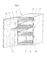
- a cooling device 1 or storage cabinet for accommodating bottles 18, in particular wine bottles, is shown with the door 20 open and with a partially pulled-out shelf 9 mounted on a telescopic rail mechanism 8.
- the fixed inside the refrigerator 1 attached shelves 22 divide the interior of the device in climates I, II III, where different temperatures can be adjusted to z. B. to adjust the appropriate temperatures for the storage of sparkling wine or champagne and red and white wine.
- the shelf 9 is formed in the embodiment shown as a frame-like support grate 2 for receiving the stored goods on the longitudinally arranged support struts 5.
- the shelf can be converted by the integration of various insert elements for different applications as well as for the provision of accessories, whereby the shelf can also be used as a so-called enjoyment preparation segment.
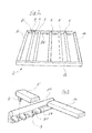
- the Fig. 2 shows the present invention formed support grid 2 in a single view.
- five support struts 5 are here used in any arrangement and with different, lateral distances.
- the tops of the support struts 5 in the inserted state are slightly below the level of the transverse struts 11, 12 and at the same level with the longitudinal struts 13, 14 of the support grid 2.
- formed on the cross struts 11, 12 barrier edges, which should prevent a possible sliding of the wine bottles from the support grid 2.
- connection means 3 which are already clearly recognizable in this drawing in the transverse strut 11, form a type of engagement contour which cooperates with pin-like engagement elements 4 attached to the support struts 5.
- the connecting means 3 are inserted according to the invention in this embodiment as a one-piece, strand-shaped profile element in a groove 27 in the transverse strut. It is also already evident here that the engagement contours formed in the profile element are designed as inwardly open engagement openings 31.
- connection technology between the support struts 5 and the cross braces 11, 12 is in this embodiment illustratively from the Fig. 3 out.
- the transverse struts 11, 12 are formed for releasable arrangement of the support struts 5 with connecting means 3, which are a series of side by side arranged engagement openings 31 have.
- the engagement openings 31 are formed open both from above and on the side facing the interior of the support grid.
- pin-like engagement elements 4 engage in the penetration.
- the engagement openings 31 are therefore designed to be open inwardly, so dimensional tolerances and also a change in length in the existing wooden supporting struts 5 can be compensated.
- the arranged on the cross braces 11,12 connecting means 3 are here preferably made of an elastic material such. B. made of plastic.
- the arranged on the cross braces connecting means 3 are formed as a one-piece, strand-shaped profile element, which is inserted into a groove 27 milled in the transverse strut 11, 12 groove. Such a profile element can be z. B. inexpensively in the plastic injection molding process.
- a support strut 5 is shown, which has on its underside at both ends depending on an engagement element 4 in the form of a pin.
- the pins 4 can be inserted into the corresponding holes 31 of the engagement contour 3. This creates a releasable connection between the frame 2 and the support strut 5, wherein a change in position of the support strut 5 within the frame 2 in a variety of arrangements is very easy.
- pin-like pin 4 are frusto-conical or conical in an advantageous embodiment, which facilitates threading into the through openings 31. Furthermore, it is ensured by this form that the pin 4 can fix sufficiently tightly in the openings. These pins 4 are also preferably made of plastic. It would of course also be possible to use a metal pin.
- the pin-like engagement elements 4 are inserted into arranged on the underside of the support struts 5 blind holes.
- a plurality of support struts 5 can be used in any number adjacent to each other or with different distances from each other in the frame 2.
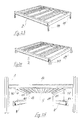
- FIG. 4 is a support grid 2 with fully equipped support struts 5 to see how it is offered in the factory delivery condition.
- the distances between the support struts 5 are chosen so that wine bottles can be stored in the Bordeaux bottle shape in an optimal position and with optimal absorption capacity on the support grid.
- In the usual standardized dimensions of a wine cabinet as shown here within the frame twelve supporting struts 5 are used.
- the frame of the support grid 2 is shown in a sectional view shown in detail, emerge from the structural features of this support grate 2.
- the lateral longitudinal struts 13,14 of the support grid 2 are formed with a rectangular profile to provide in the outwardly angled region a receiving space for a part of the telescopic rail mechanism 8 and to allow a suitable shape for cooperation with the telescopic rail mechanism 8.
- the front cross member 12 is slightly wider, so that it protrudes from the front with its upper edge as well as with its lower edge beyond the level of the longitudinal edges 13, 14 protrudes. This ensures that a barrier edge is formed in the upper region, which prevents the unwanted slipping of lying on the support grid 2 bottles.
- transverse strut 12 obscures the view into the receiving space 66 of the longitudinal struts 13, 14, so that the telescopic rail mechanism 8 engaging therein can not visually interfere.
- the connecting means 3 positively and non-positively fit into the transverse struts 11, 12.
- FIG. 6 From the FIG. 6 is a support grid 2 in a further embodiment, in which the front and the rear cross member 11, 12 and the lateral longitudinal struts 13, 14 also form a frame, in the longitudinally oriented support struts 5 can be arranged detachably and adjustably, as in the drawing is indicated by the symbolically shown arrow.
- the connecting means 3 are mounted in the interior of the frame with a kind of engagement contour, which consists in the present example of a directed towards the inside of the frame rail 33.
- a kind of engagement contour which consists in the present example of a directed towards the inside of the frame rail 33.
- this rail 33 numerous, each opening into an opening 31 slots 32 are recessed at the same distance.
- the opening 31 and the slots 32 are formed according to the invention as being open from above and open towards the interior engagement openings 31.
- the rail with the engagement contours 3 can be attached either as a separate part below or on the inside of the transverse struts 11, 12.
- the preferably made of wood cross struts 11, 12 may be formed with the connecting means 3 but also as a one-piece molding.
- engaging apertures 31 is meant that the pin-like engaging element attached to the support struts 5 can dip into an opening of the connecting means 3 when inserted into the frame from above, and that there is some play between the engaging apertures 31 and the engaging elements 4 is, whereby a tolerance compensation and compensation due to the material expansion of the existing wooden support struts 5 can take place.
- the spacing of the engagement openings 31 in the connecting means 3 of the transverse struts 11, 12 is also tuned here with the width of the support struts 5 and the arrangement of the corresponding engagement elements 4, that the support struts 5 at any distance from each other or directly adjacent to each other in the frame can be used ,
- a support grid 2 is shown, in which the rear cross member 11 is provided with an attachment 6 in order to create an inclined support possibility for the wine bottles to be stored.
- This attachment 6 also has the connecting means 3 according to the invention.
- 11 not shown here means are provided on the attachment part 6 and the rear cross member, which allow an easily detachable and connectable coupling of these parts.
- the attachment 6 and the rear cross struts 11 may also be integrally formed.
- a further embodiment of a support grid 2 is shown, in which recesses are incorporated in the front, slightly wider transverse strut 12 of the frame at the top, can be inserted into the accessories 40, such. B. spout, bottle opener, etc.
- accessories 40 such. B. spout, bottle opener, etc.
- this area As an alternative would also be considered to form this area as a separate part, which could be placed or coupled to the front cross member 12.
- the Fig. 9 shows a support grid 2, which is covered with a fabric 50 - here preferably made of leather.
- a fabric 50 - here preferably made of leather.
- support struts 5 can be trough-shaped receptacles, for example, for the storage of wine bottles form, as can be seen clearly from the drawing.
- Such an embodiment could come in particular for a higher quality equipment or for particularly fine wines in question.
- a fabric made of leather there are also versions that made of another suitable material, such as here z. B. consist of a mesh material 51 ( Fig. 10 ).
- FIGS. 11 to 14 show applications of special applications that can be used in the supporting grate 2 according to the invention.
- FIG. 11 u. 12 variants are shown, in which an insert 10 below its support floor 53 has a drawer 54 which is mounted extendable in a corresponding extension device 55.
- This additional part can be dimensioned so that only a part ( Fig. 8 ) or the entire part ( Figure 9 ) of the support grid is filled.
- FIGS. 13 and 14 show a support grid 2, in which an insert 10 partially or completely with a glass plate 56 can be flush in shape in the support grid 2, can be used.
- hangers that form a kind of side rail 57 and are also intended as a handle for the handling of this insert 10.
- the inserts 10, as exemplified by the FIGS. 11 to 14 emerge, may be designed in their construction such that they rest on the support struts 5 and / or on the longitudinal struts 13, 14. But it is also possible that the inserts 10 come only on the attached to the cross braces 11, 12 connecting means 3 for support.
- FIG. 15 is shown in a partial view of a grate 5 in a wine cabinet in the partially pulled out state.
- wine bottles 18 are stored laterally and in the middle of an insert 10 is inserted on the drinking glasses 60 or in addition also bottles can be parked.
- a suitable insert 10 is in FIG. 16 shown as a detail.
- the differently dimensioned trough-shaped recesses 60 and 61 in the support base 53 are used to hold drinking glasses and / or bottles or even a decanter vessel.
- the handles 62 are used for removable handling of this insert 10th
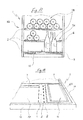
- Fig. 17 shows a partial view of the inside of the wine cabinet and illustrates in conjunction with Fig. 18 the variable and flexible uses of the supporting grid 2 according to the invention.
- FIG. 18 Shelf 9 A peculiarity of in the FIG. 18 Shelf 9 shown in detail is that here between the frame of the support grid 2 and a support strut 5, an insert 10 is inserted.
- This insert 10 can be used as a storage for objects or as a work surface for the preparation of consumption of drinks and food, such. Cheese and bread.
- the insert 10 can be used as a removable tray, wherein the structure 42 shown in the drawing can perform the function of a rail or as a handle.
- the supporting grid 2 can also be designed here such that the surfaces of the longitudinal struts 13, 14 forming the frame of the supporting grid 2 and the supporting struts 5 are aligned with the same height level.
- inserts 10 can rest with their lateral support areas on the support struts and / or the longitudinal struts 13, 14 of the frame.
- the inserts come to rest within the frame on the inwardly projecting connecting means 3.
- Fig. 19 an insert 10 which can be coupled to the supporting grid 2 is shown, which is designed as an accessory in the form of a bottle holder 64.
- This insert may be provided on the underside of its support floor 53 to improve the stability on the support struts 5 with an anti-slip material. If this is not sufficient, the support base 53 can be fastened to the support struts 5 in a suitable manner via locking means (not shown here).
- FIG. 20 Another embodiment of an insert 10 is in the FIG. 20 shown.
- the insert 10 is used as a recording box or as a box for receiving and maintaining various utensils.
- the insert 10 consists of a box 58 which can be closed by a cover 23.
- a negative contour is present for each of the three objects 15, 16, 17 shown, so that the objects are held fixed in position in the insert 10.
- each grip recesses 25 in the area of the objects 15, 16, 17 are also present.
- the insert is placed laterally on two support struts 5, which in the FIG. 10 only hinted at.
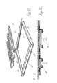
- FIGS. 21 and 22 show a further interesting embodiment and useful functionality of the support struts 5.
- 5 receiving devices 65 are mounted for the hanging storage of drinking glasses 7 below the support struts.
- the recording devices 65 are formed as simple angle profiles.
- the supporting grates 2 mounted on the telescopic rail mechanism 8 can be equipped with damping means 44.
- the arranged on the support grid 5 damping means 44 are formed for engagement in the telescopic rail mechanism 8 as struts.
- the example according to Fig. 24 is provided to attach to the support grid molded silicone elements that can engage positively in corresponding receptacles of the telescopic rail mechanism 8.
- Fig. 25 is shown a simple solution in which as damping means 44, an elastic molding 45, for example a rubber part, is provided which can engage in openings 46, 47 of the longitudinal struts 13, 14 and which can be slipped onto the support pins 81 of the telescopic rail 8.
- the openings 47 on one of the longitudinal struts 13, 14 are oval or formed as a slot to facilitate the placement of the support grid 2 on the telescopic rail 8.
- FIG. 26 To illustrate the mechanics of the telescopic rail mechanism 8 within the storage cabinet 1 and to cover in a visually appealing manner, a cover 19 is placed here on the telescopic rail mechanism 8.
- This cross-sectionally approximately U-shaped cover 19 is made of plastic and is placed on the telescopic rail mechanism 8.
- the telescopic rail mechanism 8 is in turn mounted in this case on a raised contour 26 of the storage cabinet, which forms a kind of mounting bracket for the telescopic rail mechanism 8.
- the fixation of the cover 19 on the telescopic rail mechanism 8 or on the inner wall of the storage cabinet 1 can take place via corresponding clamping or latching connection elements.
- the fixing can be effected by cooperating by magnetic force holding elements on the telescopic rail mechanism 8 or on the inner wall of the storage cabinet 1.
- magnetic elements 83 are glued to the inside of the cover 19, which provide with the metal part 82 of the telescopic rail mechanism 8 for the sufficient fixation of the cover 19 on the telescopic rail mechanism 8.
- a particularly useful additional device is achieved by the design of the shelf with marking elements 43, as shown by the FIGS. 27 to 29 is explained.
- FIGS. 27 and 28 In the clipping representations of the FIGS. 27 and 28 the support grid 2 is shown once with and once without the support struts 5.
- the marking elements 43 indicated on the connecting means 3 point out to the user where the supporting struts 5 are in the standard setting (FIG. Fig. 28 ) must be placed.
- These marking elements 43 serve primarily to find predetermined positions for the placement of the support struts. Furthermore, the standard or factory setting with the optimal average distance between adjacent support struts 5 can be restored to allow the storage of as many bottles as possible according to the Bordeaux bottle standard on a support grid.
- the marking elements 43 are arranged for receiving the support struts 5 in various forms. This can be realized by a label, engravings, color design and by additional marking carrier such as adhesive tape or the like.
Abstract
Description
Die Erfindung betrifft einen Fachboden für einen Vorratsschrank zur Lagerung und Temperierung von Getränkeflaschen und/oder andere zylindrische Behälter, insbesondere zur klimatisierten und/oder temperierten Lagerung von Weinflaschen gemäß dem Oberbegriff des Anspruchs 1 sowie einen Vorratsschrank gemäß Anspruch 24.The invention relates to a shelf for a storage cabinet for storage and temperature control of beverage bottles and / or other cylindrical container, in particular for the conditioned and / or tempered storage of wine bottles according to the preamble of
Es sind Vorratsschränke der vorgenannten Art auf dem Markt, die sich z.B. als Weintemperierschränke zunehmender Beliebtheit erfreuen. Diese Vorratsschränke zur klimatisierten und/oder temperierten Getränkelagerung sind beispielsweise für Weinliebhaber von Bedeutung, die darauf bedacht sind, ihre Weine oder verschiedene Weinsorten exakt bei den erforderlichen Lagertemperaturen aufzubewahren. Darüber hinaus ist es jedoch mit einem derartigen Vorratsschrank möglich, auch andere Getränkesorten wie Bier, Wein, Whisk(e)y gemeinsam oder sortiert zu lagern. Bekannte Vorratsschränke verfügen hierzu über mehrere Klimazonen, in denen unterschiedliche Temperaturen eingeregelt werden können.There are storage cabinets of the aforementioned type on the market, which are e.g. as Weintemperierschrank enjoy increasing popularity. These storage cabinets for air-conditioned and / or tempered beverage storage are important for wine lovers, for example, who are anxious to keep their wines or different types of wine exactly at the required storage temperatures. In addition, however, it is possible with such a storage cabinet, other types of drinks such as beer, wine, Whisk (e) y stored together or sorted. Known storage cabinets have this several climate zones in which different temperatures can be adjusted.
In einer weit verbreiteten Ausführungsform von Weintemperierschränken werden für die Lagerung der Weinflaschen Tragroste aus Holz verwendet, die einen aus Quer- und Längsstreben gebildeten Rahmen aufweisen. Die der Auflage von Weinflaschen dienenden Tragstreben sind in diesem Rahmen in Längsrichtung parallel nebeneinander angeordnet und mit dem Rahmen unlösbar verbunden. Die so gebildeten Tragroste sind dabei auf einem im Gerät angeordneten Teleskopschienenmechanismus lösbar und herausziehbar gelagert. Nachteilig bei diesen Tragrosten ist es, dass die starre Anordnung der Tragstreben keine optimale und an unterschiedliche Flaschenformen angepasste Auflagemöglichkeit erlaubt. Außerdem bereitet es hier Schwierigkeiten zusätzliches Zubehör bereitzuhalten oder andere Nutzungsmöglichkeiten vorzusehen. Weiterhin ist bei diesen Tragrosten eine stehende Lagerung der Flaschen im Vorratsschrank ohne zusätzliche Haltemechanismen kaum möglich.In a widespread embodiment of wine tempering cabinets wooden support grates are used for the storage of wine bottles, which have a frame formed from transverse and longitudinal struts. Serving the edition of wine bottles supporting struts are arranged in this frame in the longitudinal direction parallel to each other and inextricably linked to the frame. The support grates formed in this way are releasably and removably mounted on a telescopic rail mechanism arranged in the device. A disadvantage of these supporting grates is that the rigid arrangement of the support struts does not allow optimal and adapted to different bottle shapes support option. In addition, it is difficult here to provide additional accessories or provide other uses. Furthermore, a standing storage of the bottles in the storage cabinet without additional holding mechanisms is hardly possible in these supporting grates.
Um hier Abhilfe zu schaffen und in diesem Zusammenhang eine flexible Handhabung zu ermöglichen, wurde bereits in der
Eine weitere Ausführungsform eines Kühlgerätes mit herausziehbaren Tragrosten und einer Verstellbarkeit der Tragstreben geht aus der
Der Erfindung stellt sich somit das Problem, die vorbeschriebenen Nachteile zu vermeiden und einen Fachboden der Eingangs genannten Art zu schaffen, bei dem die Verstellbarkeit der Tragstreben in einfacher Weise und mit einfachen Mitteln realisiert werden kann. Ferner soll eine flexible Anwendung von unterschiedlichen Nutzungsmöglichkeiten erreicht werden und es sollen sich zusätzliche Einsatzmöglichkeiten innerhalb des Kühlgerätes eröffnen.The invention thus raises the problem of avoiding the disadvantages described above and to provide a shelf of the aforementioned type in which the adjustability of the support struts can be realized in a simple manner and with simple means. Furthermore, a flexible application of different uses is to be achieved and it should open up additional applications within the refrigerator.
Erfindungsgemäß wird dieses Problem durch einen Fachboden mit den Merkmalen des uanbhängigen Patentanspruchs 1 gelöst. Vorteilhafte Ausgestaltungen und Weiterbildungen der Erfindung ergeben sich aus den nachfolgenden Unteransprüchen. Ein mit dem erfindungsgemäßen Fachboden ausgerüsteter Vorratsschrank ergibt sich aus Anspruch 24.According to the invention this problem is solved by a shelf with the features of
Mit der neuen, erfindungsgemäßen Konzeption des Fachbodens lässt sich mit einfachen und kostengünstig herstellbaren Mitteln eine ebenfalls in der Handhabung äußerst einfache Verstellmöglichkeit der Tragstreben innerhalb des Rahmens realisieren.With the new conception of the shelf according to the invention can be realized with simple and inexpensive to produce means also in handling extremely simple adjustment of the support struts within the frame.
Die mit der Erfindung erreichbaren Vorteile bestehen weiterhin darin, dass sich durch einfaches Umrüsten neben der liegenden auch die stehende Lagerung von Flaschen verwirklichen lässt.The achievable with the invention advantages continue to be that can be realized by simply retooling in addition to the lying and the standing storage of bottles.
Außerdem können in dem neuartigen Fachboden unterschiedliche Einsätze in einfacher Weise integriert werden und es eröffnen sich dadurch zusätzliche Nutzungsmöglichkeiten für die Genussvorbereitung.In addition, different inserts can be integrated in a simple manner in the novel shelf, thereby opening up additional possibilities for use in preparing for enjoyment.
Auch die Bereithaltung von Zubehör im Zusammenhang mit dem Verzehr der Getränke kann hier in unterschiedlichsten Ausführungen ermöglicht werden.The provision of accessories in connection with the consumption of the drinks can be made possible here in various designs.
Weiterhin ist es von besonderem Vorteil, dass sich mit dem erfindungsgemäßen Fachboden eine ziemlich vibrationsfreie Lagerung von Flaschen erreichen lässt, was bekanntlich insbesondere für kostbare Weine von erheblicher Bedeutung ist.Furthermore, it is of particular advantage that can achieve a fairly vibration-free storage of bottles with the shelf according to the invention, which is known, especially for precious wines of considerable importance.
Eine erfindungsgemäß zumindest an der hinteren Querstrebe des Fachbodens vorgesehene Markierungshilfe erleichtert dem Benutzer z.B. die Wiederherstellung der Standardeinstellung für die einzusetzenden Tragstreben. Nachdem der Benutzer die Abstände der Tragstreben vorher einmal verändert oder einen Teil der Tragstreben ganz entfernt hatte, kann er zur optimalen Kapazitätsausnutzung das auf die Lagerung von Weinflaschen in der Form von Bordeauxflaschen ausgerichtete Abstandsmaß wieder herstellen. Ferner können Markierungselemente angebracht sein, die bestimmte Abstände für die einzusetzenden Tragstreben zur Aufnahme anderer Flaschenformen oder bestimmte Abstände für die einzusetzenden Einsatzelemente vorgeben.A marking aid provided according to the invention at least on the rear cross member of the shelf facilitates the user e.g. the restoration of the standard setting for the supporting struts to be used. Once the user has previously changed the spacing of the support struts or completely removed some of the support struts, he can restore the distance dimensioned for the storage of wine bottles in the form of Bordeaux bottles for optimum capacity utilization. Furthermore, marking elements can be attached, which specify specific distances for the support struts to be used for receiving other bottle shapes or specific distances for the insert elements to be used.
Insgesamt ergibt sich mit dem erfindungsgemäßen Fachboden eine hohe Flexibilität in der Anwendung des Tragrostes und vielfältige Nutzungsmöglichkeiten in Verbindung mit dem Genuss von weinartigen Getränken.Overall, with the shelf according to the invention a high flexibility in the application of the support grate and a variety of uses in conjunction with the enjoyment of wine-like drinks.
Ein Ausführungsbeispiel der Erfindung ist in den Zeichnungen rein schematisch dargestellt und wird nachfolgend näher beschrieben. Es zeigt:
- Figur 1:
- eine perspektivische Ansicht eines Kühlgerätes zur klimatisierten und/oder temperierten Getränkelagerung;
- Figur 2:
- ein erfindungsgemäßer Tragrost in Einzeldarstellung in einer perspektivischen Ansicht;
- Figur 3:
- in perspektivischer Ansicht und Explosionsdarstellung und in einem Ausschnitt im Detail eine erste Ausführungsform für den Einsatz der Tragstreben in einem Tragrost gemäß
Fig. 2 ; - Figur 4:
- ein erfindungsgemäßer Tragrost in Einzeldarstellung in einer perspektivischen Ansicht und mit komplett bestückten Tragstreben;
- Figur 5:
- den erfindungsgemäßen Tragrost ausschnittsweise in einer perspektivischen Schnittdarstellung;
- Figur 6:
- eine zweite Ausführungsform eines Tragrostes und der Verbindungsmittel für die Aufnahme der Tragstreben in dem Tragrost in einer perspektivischen Explosionsdarstellung;
- Figur 7:
- eine Ausführungsvariante des Tragrostes in perspektivischer Ansicht mit einer Zusatzvorrichtung zur Höhenverstellung der Tragstreben;
- Figur 8:
- eine Ausführungsvariante des Tragrostes in einer speziellen Ausgestaltung zur Aufnahme von Zubehör in perspektivischer Ansicht;
- Figur 9:
- eine Ausführungsvariante des Tragrostes mit der Bespannung einer Stoffbahn aus Leder in perspektivischer Ansicht;
- Figur 10:
- eine Ausführungsvariante des Tragrostes mit einer geflechtartigen Bespannung in perspektivischer Ansicht;
Figur 11, 12:- zwei Ausführungsvarianten des Tragrostes mit einem Einsatz und einer daran befestigten Schublade in perspektivischer Ansicht und in Explosionsdarstellung;
Figur 13, 14:- zwei Ausführungsvarianten des Tragrostes mit einem Einsatz in Form einer Glasscheibe als Abstell- und Arbeitsfläche in perspektivischer Ansicht;
- Figur 15:
- in einer Teilansicht einen Tragrost in perspektivischer Ansicht zur Aufnahme von Flaschen und Trinkgläser;
- Figur 16:
- in perspektivischer Einzeldarstellung einen Einsatz mit Mulden zur stehenden Aufnahme von Gläsern und einer Weinflasche oder eines Dekanters;
- Figur 17:
- in einer Teildarstellung in Vorderansicht das Innere eines Kühlgerätes mit liegend und stehend gelagerten Flaschen;
- Figur 18:
- eine Ausführungsvariante des Tragrostes in perspektivischer Darstellung mit einem eingesetzten Einsatzelement;
- Figur 19:
- in perspektivischer Darstellung den Tragrost mit einem Einsatz zur Halterung einer Getränkeflasche;
- Figur 20:
- in perspektivischer Darstellung ein zwischen zwei Tragstreben eingesetztes Einsatzelement zur Aufnahme von Zubehör, mit Blick in einen verschließbaren Einsatz;
- Figur 21:
- in perspektivischer Ansicht einen Tragrost und in Explosionsdarstellung mit speziell ausgebildeten Tragstreben, zur Aufnahme von Gläsern;
- Figur 22:
- ausschnittsweise in vereinfachter Schnittdarstellung die gemäß
Figur 20 ausgebildeten Tragstreben mit eingehängten Gläsern; Figur 23,24:- in perspektivischer Ansicht einen Tragrost mit an den Verbindungsmitteln zum Teleskopschienenmechanismus angebrachten Dämpfungselementen;
- Figur 25:
- in perspektivischer Teilansicht und in Explosionsdarstellung einen Tragrost in Verbindung mit dem Teleskopschienenmechanismus;
- Figur 26:
- ausschnittsweise in perspektivischer Teilansicht den auf der Innenseite des Vorratsschrankes angeordneten Teil der Auszugsschiene für den Teleskopschienenmechanismus;
Figur 27, 28:- ausschnittsweise in einer Teilansicht und in vereinfachter Prinzipskizze einen Tragrost mit positionierten Tragstreben in der Werkseinstellung und Markierungshilfen;
- Figur 29:
- ausschnittsweise in perspektivischer Ansicht und in Explosionsdarstellung einen Tragrost mit angebrachten Markierungshilfen.
- FIG. 1:
- a perspective view of a refrigerator for air-conditioned and / or tempered beverage storage;
- FIG. 2:
- an inventive support grid in an individual representation in a perspective view;
- FIG. 3:
- in a perspective view and exploded view and in a detail in detail a first embodiment of the use of the support struts in a support grid according to
Fig. 2 ; - FIG. 4:
- an inventive support grid in an individual view in a perspective view and with fully equipped support struts;
- FIG. 5:
- the support grid according to the invention fragmentary in a perspective sectional view;
- FIG. 6:
- a second embodiment of a support grid and the connecting means for receiving the support struts in the support grid in an exploded perspective view;
- FIG. 7:
- a variant of the support grid in perspective view with an additional device for height adjustment of the support struts;
- FIG. 8:
- a variant of the support grid in a special embodiment for receiving accessories in perspective view;
- FIG. 9:
- a variant of the support grid with the covering of a fabric made of leather in perspective view;
- FIG. 10:
- a variant of the support grid with a braided fabric in perspective view;
- FIGS. 11, 12:
- two embodiments of the support grid with an insert and a drawer attached thereto in a perspective view and in exploded view;
- FIGS. 13, 14:
- two embodiments of the support grid with an insert in the form of a glass as a storage and working surface in a perspective view;
- FIG. 15:
- in a partial view of a supporting grid in perspective view for receiving bottles and drinking glasses;
- FIG. 16:
- in perspective detail representation an insert with hollows for standing recording of glasses and a wine bottle or a decanter;
- FIG. 17:
- in a partial view in front view of the interior of a refrigerator with lying and standing upright bottles;
- FIG. 18:
- a variant of the support grid in perspective view with an inserted insert element;
- FIG. 19:
- in a perspective view of the support grid with an insert for holding a beverage bottle;
- FIG. 20:
- in perspective view an inserted between two support struts insert element for receiving accessories, with a view into a lockable insert;
- FIG. 21:
- in a perspective view of a support grid and in exploded view with specially trained support struts, for holding glasses;
- FIG. 22:
- partially in simplified sectional view according to
FIG. 20 trained support struts with hinged glasses; - Figure 23,24:
- in perspective view a supporting grid with attached to the connecting means to the telescopic rail mechanism damping elements;
- FIG. 25:
- in a perspective partial view and in exploded view a supporting grid in connection with the telescopic rail mechanism;
- FIG. 26:
- partially in perspective partial view of the arranged on the inside of the storage cabinet part of the pull-out rail for the telescopic rail mechanism;
- FIGS. 27, 28:
- partial view in a partial view and in a simplified schematic sketch a support grid with positioned support struts in the factory setting and marking aids;
- FIG. 29:
- partially in perspective view and in exploded view a carrying grid with attached marking aids.
In der
Die fest im Inneren des Kühlgerätes 1 angebrachten Trennböden 22 teilen den Innenraum des Gerätes in Klimazonen I, II III, in denen unterschiedliche Temperaturen eingeregelt werden können, um z. B. die geeigneten Temperaturen für die Lagerung von Sekt oder Champagner sowie Rot- und Weißwein einstellen zu können.The fixed inside the
Der Fachboden 9 ist in der gezeigten Ausführung als rahmenartiger Tragrost 2 zur Aufnahme des Lagergutes auf den in Längsrichtung angeordneten Tragstreben 5 ausgebildet. Nachfolgend wird noch näher darauf eingegangen, wie sich der Fachboden durch die Integration diverser Einsatzelemente für unterschiedliche Anwendungsfälle sowie für die Bereithaltung von Zubehör umrüsten lässt, wodurch sich der Fachboden auch als ein so genanntes Genussvorbereitungssegment nutzen lässt.The
Die
Wie in der Zeichnung zu sehen ist, liegen die Oberseiten der Tragstreben 5 im eingesetzten Zustand etwas unterhalb des Niveaus der Querstreben 11, 12 und auf gleichem Niveau mit den Längsstreben 13, 14 des Tragrostes 2. Durch diese Anordnung bilden sich an den Querstreben 11, 12 Barrierekanten, die ein mögliches Abgleiten der Weinflaschen von dem Tragrost 2 verhindern sollen.As can be seen in the drawing, the tops of the support struts 5 in the inserted state are slightly below the level of the transverse struts 11, 12 and at the same level with the
Die in dieser Zeichnung in der Querstrebe 11 bereits gut erkennbaren Verbindungsmittel 3 bilden eine Art Eingriffskontur, die mit an den Tragstreben 5 angebrachten zapfenartige Eingriffselemente 4 zusammenwirken.The connection means 3, which are already clearly recognizable in this drawing in the
Die Verbindungsmittel 3 sind bei dieser Ausführungsform erfindungsgemäß als einteiliges, strangförmiges Profilelement in einer Nut 27 in der Querstrebe eingefügt. Ebenfalls ist hier bereits ersichtlich, dass die in dem Profilelement gebildeten Eingriffskonturen als nach innen offene Eingriffsöffnungen 31 ausgebildet sind.The connecting means 3 are inserted according to the invention in this embodiment as a one-piece, strand-shaped profile element in a
Die Art und Weise der Verbindungstechnik zwischen den Tragstreben 5 und den Querstreben 11, 12 geht bei dieser Ausführungsform anschaulich aus der
Bei dieser Ausführungsform sind die Querstreben 11, 12 zur lösbaren Anordnung der Tragstreben 5 mit Verbindungsmitteln 3 ausgebildet, die eine Reihe von nebeneinander angeordneten Eingriffsöffnungen 31 aufweisen. Die Eingriffsöffnungen 31 sind dabei sowohl von oben als auch auf der zum Inneren des Tragrostes gerichteten Seite offen ausgebildet. In diese Eingriffsöffnungen 31 können die an den Tragstreben 5 angeordneten, stiftartigen Eingriffselemente 4 im Durchgriff eingreifen. Die Eingriffsöffnungen 31 sind deshalb nach innen offen gestaltet, damit Maßtoleranzen und auch eine Längenveränderung bei den aus Holz bestehenden Tragstreben 5 ausgeglichen werden können.In this embodiment, the transverse struts 11, 12 are formed for releasable arrangement of the support struts 5 with connecting
Die an den Querstreben 11,12 angeordneten Verbindungsmittel 3 sind hier vorzugsweise aus einem elastischen Material, wie z. B. aus Kunststoff ausgebildet. In bevorzugter Ausführung sind die an den Querstreben angeordneten Verbindungsmittel 3 als einteiliges, strangförmiges Profilelement ausgebildet, welches in eine in der Querstrebe 11, 12 eingefräste Nut 27 einsetzbar ist. Ein derartiges Profilelement lässt sich z. B. kostengünstig im Kunststoffspritzverfahren herstellen.The arranged on the cross braces 11,12 connecting
Anstelle eines Kunststoffteils käme auch der Einsatz eines im Stanzverfahren herzustellenden Blechteils in Betracht.Instead of a plastic part, the use of a sheet metal part to be produced by stamping would also be considered.
Beispielhaft ist in der
Die an den Tragstreben 5 angeordneten, stiftartigen Zapfen 4 sind in einer vorteilhaften Ausgestaltung kegelstumpfförmig bzw. konisch ausgebildet, was das Einfädeln in die Durchgriffsöffnungen 31 erleichtert. Weiterhin wird durch diese Form dafür gesorgt, dass sich die Zapfen 4 hinreichend festklemmend in den Öffnungen fixieren können. Diese Zapfen 4 sind ebenfalls vorzugsweise aus Kunststoff hergestellt. Möglich wäre es natürlich auch, einen Metallstift zu verwenden. Die stiftartigen Eingriffselemente 4 sind in an der Unterseite der Tragstreben 5 angeordnete Sackbohrungen eingesetzt.The arranged on the support struts 5, pin-
Anhand der Darstellung der
In der
In der
Aus der
Entlang der Querstreben 11, 12 sind im Innern des Rahmens die Verbindungsmittel 3 mit einer Art Eingriffskontur angebracht, die im vorliegenden Beispiel aus einer zum Innen des Rahmens gerichteten Schiene 33 besteht. In dieser Schiene 33 sind mit gleichem Abstand zahlreiche, jeweils in eine Öffnung 31 mündende Schlitze 32 eingelassen. Die Öffnung 31 und die Schlitze 32 sind dabei erfindungsgemäß als von oben offene und zum Inneren hin offene Eingriffsöffnungen 31 ausgebildet.Along the transverse struts 11, 12, the connecting
Auch mit einer derartigen Ausbildung der Verbindungsmittel 3 und den Eingriffskonturen ist es in einfacher Weise möglich, verschiedene Tragstreben 5 in den Rahmen des Tragrostes 2 lösbar und verstellbar einzusetzen.Even with such a design of the connecting
Die Schiene mit den Eingriffskonturen 3 kann entweder als separates Teil unterhalb oder auf der Innenseite der Querstreben 11, 12 befestigt werden. Die vorzugsweise aus Holz gefertigten Querstreben 11, 12 können mit den Verbindungsmittel 3 aber auch als einteiliges Formteil ausgebildet sein.The rail with the
Mit dem Begriff "Eingriffsöffnungen 31" ist zu verstehen, dass das an den Tragstreben 5 angebrachte stiftartige Eingriffselement beim Einsetzen in den Rahmen von oben in eine Öffnung des Verbindungsmittels 3 eintauchen kann, und dass ein gewisses Spiel zwischen den Eingriffsöffnungen 31 und den Eingriffselementen 4 vorhanden ist, wodurch ein Toleranzausgleich und ein Ausgleich aufgrund der Materialausdehnung der aus Holz bestehenden Tragstreben 5 stattfinden kann.By the term "engaging
Der Abstand der Eingriffsöffnungen 31 in den Verbindungsmitteln 3 der Querstreben 11, 12 ist auch hier derart mit der Breite der Tragstreben 5 und der Anordnung der korrespondieren Eingriffselemente 4 abgestimmt, dass die Tragstreben 5 in einem beliebigen Abstand zueinander oder direkt aneinander anliegend im Rahmen einsetzbar sind.The spacing of the
In der
In der
Die
Die
In den
In einer anderen Ausgestaltung könnten auch unterhalb der Tragstreben 5 und/oder der Längsstreben 13, 14 des Tragrostes 2 Auszugsvorrichtungen 55 für die herausziehbare Anordnung eines Schubkastens 29 befestigt sein, was eine individuelle und flexible Gestaltung hinsichtlich der Größe der Schubkästen 54 ermöglicht.In another embodiment could also be below the support struts 5 and / or the
Die Ausführungsformen gemäß
Die Einsätze 10, wie sie beispielhaft aus den
In der
Ein hierfür geeigneter Einsatz 10 ist in
Die
Im Bereich der unteren Klimazone III sind hier drei übereinander angeordnete Tragroste 2 gezeigt, wobei im mittleren Tragrost 2 durch Weglassung einiger Tragstreben 5 eine Öffnung 24 entstanden ist, durch die die auf dem unteren Tragrost 2 stehend gelagerten Flaschen 18 hindurchragen können. Im unteren Tragrost 2 sind unterhalb dieser Öffnung mehrere, unmittelbar nebeneinander angeordnete Tragstreben 5 eingesetzt, so dass hier die Abstellfläche für die stehende Lagerung der Flaschen 18 gebildet ist. Daneben ist in diesem Tragrost 2 noch die Anordnung eines Einsatzes 10 zu sehen, worauf nachstehend noch näher eingegangen wird. Die übrigen Flaschen 18 innerhalb dieser Klimazone III des Vorratsschrankes 1 sind wie gezeigt in herkömmlicher Weise liegend gelagert.In the area of the lower climate zone III three
Eine Besonderheit des in der
Neben diesem Einsatz sind mehrere unmittelbar nebeneinander angeordnete Tragstreben 5 in dem Tragrost 2 eingesetzt, so dass sich hier eine weitere Abstellfläche z. B. für Flaschen und andere Gegenstände ergibt. In dem Bereich neben dieser Abstellfläche können weitere Tragstreben 5 oder andere Einsätze je nach Bedarf vorgesehen werden. Es kann aber auch - wie in
Um die vorstehend beschriebenen Funktionalitäten zu ermöglichen und variable Einsatzmöglichkeiten zu schaffen kann der Tragrost 2 auch hier so ausgebildet sein, dass die Oberflächen der den Rahmen des Tragrostes 2 bildenden Längstreben 13, 14 sowie die Tragstreben 5 auf das gleiche Höhenniveau ausgerichtet sind. Somit können Einsätze 10 mit ihren seitlichen Abstützbereichen auf den Tragstreben und/oder den Längstreben 13, 14 des Rahmens aufliegen. Weiterhin ist es auch möglich, dass die Einsätze innerhalb des Rahmens auf den nach Innen abstehenden Verbindungsmitteln 3 zur Auflage kommen.In order to enable the above-described functionalities and to create variable fields of application, the supporting
Sollten die Längstreben 13, 14 oder die Tragstreben auf der Oberseite mit einem unterschiedlichen Niveau ausgerichtet sein, wären diese Höhenunterschiede natürlich durch hier nicht näher gezeigte Abstandselemente auszugleichen.If the
In
Eine andere Ausführungsvariante eines Einsatzes 10 ist in der
Im hier gezeigten Beispiel besteht der Einsatz 10 aus einem Kasten 58, der durch einen Deckel 23 verschließbar ist. In dem Kasten ist für jeden der drei dargestellten Gegenstände 15, 16, 17 je eine negative Kontur vorhanden, so dass die Gegenstände lagefixiert in dem Einsatz 10 aufgenommen sind. Zur Erleichterung der Entnahme der Gegenstände 15, 16, 17 aus dem Einsatz 10 sind darüber hinaus jeweils Griffmulden 25 im Bereich der Gegenstände 15, 16, 17 vorhanden. Der Einsatz ist hierbei seitlich auf zwei Tragstreben 5 aufgesetzt, was in der
Die
Aus den
In der
Die
In einer vorteilhaften Ausgestaltung kann die Fixierung durch mittels Magnetkraft zusammenwirkende Halteelemente an dem Teleskopschienenmechanismus 8 oder der an der Innenwand des Vorratsschrankes 1 bewirkt werden. Bei der in
Eine besonders nützliche Zusatzeinrichtung wird durch die Ausgestaltung des Fachbodens mit Markierungselementen 43 erzielt, wie dies anhand der
In den Ausschnittsdarstellungen der
Diese Markierungselemente 43 dienen in erster Linie dazu, vorbestimmte Positionen für die Platzierung der Tragstreben zu finden. Weiterhin kann die Standard- bzw. Werkseinstellung mit dem optimalen Durchschnittsabstand benachbarter Tragstreben 5 wieder hergestellt werden, um die Lagerung möglichst vieler Flaschen gemäß dem Bordeauxflaschen-Standard auf einem Tragrost zu ermöglichen.These marking
In der
- 1.1.
- Vorratsschrankpantry
- 2.Second
- Tragrostsupport grid
- 3.Third
- Verbindungsmittel (Eingriffskonturen)Connecting means (engagement contours)
- 31.31st
- Eingriffsöffnungenengagement openings
- 32.32nd
- Schlitzeslots
- 33.33rd
- Schienerail
- 4.4th
- Eingriffselement (zapfenartig)Engaging element (peg-like)
- 5.5th
- Tragstrebesupporting strut
- 6.6th
- Aufsatzteilattachment
- 7.7th
- Trinkgläserdrinking glasses
- 8.8th.
- TeleskopschienenmechanismusTelescopic rail mechanism
- 8181
- Tragzapfensupporting journal
- 8282
- Teil des TeleskopschienenmechanismusPart of the telescopic rail mechanism
- 8383
- Magnetelementemagnetic elements
- 9.9th
- Fachboden (Genussvorbereitungssegment)Shelf (pleasure preparation segment)
- 10.10th
- Einsatzcommitment
- 11.11th
- Querstrebe, hintenCross strut, rear
- 12.12th
- Querstrebe, vorneCross strut, front
- 13.13th
- Längsstrebe, linksLongitudinal strut, left
- 14.14th
- Längsstrebe, rechtsLongitudinal strut, right
- 15.15th
- Gegenstandobject
- 16.16th
- Gegenstandobject
- 17.17th
- Gegenstandobject
- 18.18th
- Flaschebottle
- 19.19th
- Abdeckungcover
- 20.20th
- Türdoor
- 21.21st
- Sichtfensterwindow
- 22.22nd
- Trennbodenseparating base
- 23.23rd
- Deckelcover
- 24.24th
- Öffnungopening
- 25.25th
- Griffmuldegrip
- 26.26th
- Konturcontour
- 27.27th
- Nutgroove
- 28.28th
- Auszugsvorrichtungextracting device
- 29.29th
- Schubkastendrawer
- 40.40th
- ZubehörteileAccessories
- 43.43rd
- Markierungselementemarkers
- 4444
- Dämpfungsmitteldamping means
- 4545
- Formteilmolding
- 4646
- Öffnungenopenings
- 4747
- Öffnungen, LanglochOpenings, oblong hole
- 5050
- Stoffbahn/LederFabric / leather
- 5151
- Geflechtweave
- 5252
- Ausnehmungen, muldenförmigRecesses, trough-shaped
- 5353
- Tragbodensupport base
- 5454
- Schubkastendrawer
- 5555
- Auszugsvorrichtungextracting device
- 5656
- Glasplatteglass plate
- 5757
- Reling (Bügel)Railing
- 5858
- Kastenbox
- 6060
- Ausnehmungenrecesses
- 6161
- Ausnehmungenrecesses
- 6262
- Handgriff, DekBrettHandle, DekBrett
- 6363
- Aufbau, (Reling, Handgriff)Construction, (railing, handle)
- 6464
- Flaschenhalterungbottle holder
- 6565
- Aufnahmevorrichtungcradle
- 6666
- Aufnahmeraumaccommodation space
- I, II, IIII, II, III
- Klimazone des VorratsschrankesClimate zone of the storage cupboard
Claims (24)
einen rahmenartigen Tragrost zur Aufnahme des Lagergutes sowie zur Aufnahme von im Zusammenhang mit dem Lagergut stehendes Zubehör,
einen aus Quer- und Längsstreben gebildeten Rahmen mit innerhalb des Rahmens über Verbindungsmittel lösbar und verstellbar angeordneten Tragstreben,
und wobei der Tragrost im Zusammenwirken mit einem Teleskopschienenmechanismus im Vorratsschrank herausziehbar angeordnet ist,
dadurch gekennzeichnet,
dass die Querstreben (11, 12) zur lösbaren Anordnung der Tragstreben (5) mit Verbindungsmitteln (3) ausgebildet sind, die eine Reihe von nebeneinander angeordneten Eingriffsöffnungen (31) aufweisen, in die an den Tragstreben (5) angeordnete, stiftartige Eingriffselemente (4) eingreifen.Shelf for a storage cabinet for storage and temperature control of beverage bottles and / or other cylindrical containers, in particular for the conditioned and / or tempered storage of wine bottles, comprising
a frame-like support grate for receiving the stored goods and for receiving associated with the stored goods accessories,
a frame formed from transverse and longitudinal struts with support struts detachably and adjustably arranged within the frame via connecting means,
and wherein the support grid is arranged in the storage cabinet in cooperation with a telescopic rail mechanism,
characterized,
in that the transverse struts (11, 12) are designed to detachably arrange the support struts (5) with connecting means (3) having a series of adjacent engagement openings (31) in which pin-like engagement elements (4) arranged on the support struts (5) ) intervene.
dadurch gekennzeichnet,
dass die Eingriffsöffnungen (31) einen Bereich aufweisen, in dem die Eingriffselemente (4) fixierend oder klemmend aufgenommen werden und dass daran anschließend ein Öffnungsbereich ausgebildet ist, der für einen Toleranzausgleich für die eingesetzten Tragstreben (5) bewirkt.Shelf for a storage cabinet according to claim 1,
characterized,
in that the engagement openings (31) have a region in which the engagement elements (4) are received in a fixing or clamping manner and that subsequently an opening region is formed which effects a tolerance compensation for the support struts (5).
dadurch gekennzeichnet,
dass die Eingriffsöffnungen (31) auf der zum Inneren des Tragrostes (2) gerichteten Seite offen ausgebildet sind.Shelf for a storage cabinet according to claim 1 or 2,
characterized,
in that the engagement openings (31) are open on the side facing the interior of the support grid (2).
dadurch gekennzeichnet,
dass die an den Querstreben (11, 12) angeordneten Verbindungsmittel (3) als einteiliges, strangförmiges Profilelement ausgebildet sind und in eine in den Querstreben (11, 12) eingefrästen Nut eingesetzt sind.Shelf for a storage cabinet according to one or more of the preceding claims 1 to 3,
characterized,
that the transverse struts (11, 12) are arranged connection means (3) are formed as one-piece, strand-like profile element and milled in a in the cross braces (11, 12) are inserted groove.
dadurch gekennzeichnet,
dass die an den Querstreben (11, 12) angeordneten Verbindungsmittel (3) aus einem elastischen Material, vorzugsweise aus Kunststoff ausgebildet sind.Shelf for a storage cabinet according to claim 4,
characterized,
in that the connecting means (3) arranged on the transverse struts (11, 12) are formed from an elastic material, preferably from plastic.
dadurch gekennzeichnet,
dass die an den Tragstreben (5) angeordneten, stiftartigen Eingriffselemente (4) kegelstumpfförmig oder konisch ausgebildet sind und in an der Unterseite der Tragstreben (5) angeordnete Sackbohrungen eingesetzt sind.Shelf for a storage cabinet according to one or more of the preceding claims 1 to 5,
characterized,
in that the pin-like engagement elements (4) arranged on the support struts (5) are frusto-conical or conical and are used in blind bores arranged on the underside of the support struts (5).
dadurch gekennzeichnet,
dass der Abstand der Eingriffsöffnungen (31) in den Verbindungsmitteln (3) der Querstreben (11, 12) derart mit der Breite der Tragstreben (5) und der Anordnung der korrespondieren Eingriffselemente (4) abgestimmt ist, dass die Tragstreben (5) in einem bestimmten Standardabstand, in einem beliebigen Abstand zueinander oder aneinander anliegend im Tragrost (2) einsetzbar sind.Shelf for a storage cabinet according to one or more of the preceding claims 1 to 6,
characterized,
that the distance of the engaging openings (31) in the connecting means (3) of the transverse struts (11, 12) is tuned to the width of the supporting struts (5) and the arrangement of the corresponding engaging elements (4), that the support struts (5) in a certain standard distance, at any distance from each other or adjacent to each other in the support grid (2) can be used.
dadurch gekennzeichnet,
dass die vordere Querstrebe (12) des Tragrostes (2) breiter ausgeführt ist als die hintere Querstrebe (11) und an der Oberseite Ausnehmungen aufweist, in die Zubehörteile (40) einlegbar sind.Shelf for a storage cabinet according to one or more of the preceding claims 1 to 7,
characterized,
in that the front transverse strut (12) of the supporting grid (2) is made wider than the rear transverse strut (11) and has recesses on the upper side, into which accessories (40) can be inserted.
dadurch gekennzeichnet,
dass der Tragrost (2) und die darin angeordneten Tragstreben (5) derart ausgebildet sind, dass Einsatzelemente (10) zur Aufnahme von Zubehör oder Zusatzvorrichtungen, Arbeitsflächen zur Genussvorbereitung oder als Stellflächen für Flaschen und/oder Gläser in dem Fachboden (2) integrierbar sind, wobei die Abstützbereiche der Einsatzelemente (10) auf den Tragstreben (5) und/oder den Querstreben (11, 12) und/oder den Längsstreben (13, 14) des rahmenförmigen Tragrostes (2) und/oder auf den an den Querstreben angeordneten Verbindungsmitteln (3) zur Auflage kommen können.Shelf for a storage cabinet according to one or more of the preceding claims 1 to 7,
characterized,
that the support grid (2) and disposed therein supporting struts (5) are formed such that the insert elements (10) are integrated to accommodate accessories or auxiliary devices, work surfaces for enjoyment preparation or as shelves for bottles and / or glasses in the shelf (2) in which the support regions of the insert elements (10) are arranged on the support struts (5) and / or the transverse struts (11, 12) and / or the longitudinal struts (13, 14) of the frame-shaped support grate (2) and / or on the cross struts Connection means (3) can come to rest.
dadurch gekennzeichnet,
dass das Einsatzelement (10) einen Tragboden (53) aufweist, an dessen Unterseite ein herausziehbarer Schubkasten (54) angeordnet ist.Shelf for a storage cabinet according to claim 9,
characterized,
in that the insert element (10) has a support bottom (53), on the underside of which a pull-out drawer (54) is arranged.
dadurch gekennzeichnet,
dass das Einsatzelement (10) von einer Glasplatte (56) gebildet wird, und dass die Glasplatte (56) an ihrer Oberseite im seitlichen Bereich einen bügelförmigen Aufbau in Form einer Reling (57) aufweist, die auch als Handgriff zur Handhabung des Einsatzelementes (10) dient.Shelf for a storage cabinet according to claim 9,
characterized,
in that the insert element (10) is formed by a glass plate (56), and that the glass plate (56) has a bow-shaped construction in the form of a rail (57) on its upper side in the lateral region, which is also used as a handle for handling the insert element (10 ) serves.
dadurch gekennzeichnet,
dass das Einsatzelement (10) von einem Tragboden (53) gebildet wird, in dem muldenförmige Ausnehmungen (60) und (61) zur Aufnahme von Flaschen (18) oder sonstigen Gefäßen und/oder zur Aufnahme von Trinkgläsern (7) angeordnet sind,
und dass an der Oberseite im seitlichen Bereich des Tragbodens (53) Handgriffe (62) angebracht sind.Shelf for a storage cabinet according to claim 9,
characterized,
in that the insert element (10) is formed by a support base (53) in which trough-shaped recesses (60) and (61) for accommodating bottles (18) or other vessels and / or for holding drinking glasses (7) are arranged,
and that at the top in the lateral region of the support base (53) handles (62) are mounted.
dadurch gekennzeichnet,
dass das Einsatzelement (10) als ein mit einem Deckel (23) ausgerüsteter Kasten (58) zur Aufnahme von Zubehörteilen (15, 16, 17) ausgebildet ist, die in den Zubehörteilen angepassten Ausnehmungen einlegbar sind und wobei an den Ausnehmungen Griffmulden (25) gebildet sind.Shelf for a storage cabinet according to claim 9,
characterized,
in that the insert element (10) is designed as a box (58) equipped with a lid (23) for accommodating accessories (15, 16, 17) which can be inserted into recesses adapted in the accessories and wherein recessed grips (25) are provided on the recesses. are formed.
dadurch gekennzeichnet,
dass unterhalb der Tragstreben und/oder der Längsstreben des Rahmens Auszugsvorrichtungen (28) für die herausziehbare Anordnung eines Schubkastens (29) befestigt sind.Shelf for a storage cabinet according to one or more of the preceding claims 1 to 8,
characterized,
that below the support struts and / or the longitudinal struts of the frame extraction devices (28) for the pull-out arrangement of a drawer (29) are attached.
dadurch gekennzeichnet,
dass unterhalb der Tragstreben (5) Aufnahmevorrichtungen (65) in Form von Profilwinkeln derart angebracht sind, dass zwei dieser Profilwinkel eine Aufnahmevorrichtung (65) für die hängende Aufnahme von Trinkgläsern bilden.Shelf for a storage cabinet according to one or more of the preceding claims 1 to 8,
characterized,
that below the support struts (5) receiving devices (65) are mounted in the form of profile angles such that two of these profile angle form a receiving device (65) for the hanging recording of drinking glasses.
dadurch gekennzeichnet,
dass in dem Tragrost (2) beabstandete Tragstreben (5) eingesetzt sind, wodurch eine aus Textil, Geflechtmaterial oder Leder bestehende Stoffbahn (30) im Rahmen des Tragrostes (2) und in Verbindung mit den Tragstreben (5) derart eingespannt ist, dass zwischen den Tragstreben (5) für die Aufnahme von Flaschen angepasste Mulden gebildet werden.Shelf for a storage cabinet according to one or more of the preceding claims 1 to 8,
characterized,
that in the support grid (2) spaced supporting struts (5) are inserted, whereby a textile, mesh material or leather existing fabric web (30) in the framework of the support grid (2) and in connection with the support struts (5) is clamped such that formed between the support struts (5) for receiving bottles adapted wells.
dadurch gekennzeichnet,
dass im Bereich der Querstreben (11, 12) und/oder der dieser zugeordneten Verbindungsmittel (3) zur lösbaren Aufnahme der Tragstreben (5) Markierungselemente (43) angebracht sind.Shelf for a storage cabinet according to one or more of the preceding claims 1 to 8,
characterized,
that in the region of the transverse struts (11, 12) and / or associated therewith connecting means (3) for releasably receiving the support struts (5) marking elements (43) are mounted.
dadurch gekennzeichnet,
dass die Markierungselemente (43) als Eingravierungen auf den Verbindungsmitteln (3) ausgebildet sind.Shelf for a storage cabinet according to claim 17,
characterized,
in that the marking elements (43) are formed as engravings on the connecting means (3).
dadurch gekennzeichnet,
dass an der Verbindungsstelle zwischen den Tragrosten (2) und dem Teleskopschienenmechanismus (8) Dämpfungsmittel (44) angeordnet sind.Shelf for a storage cabinet according to one or more of the preceding claims 1 to 18,
characterized,
in that damping means (44) are arranged at the connection point between the supporting grates (2) and the telescopic rail mechanism (8).
dadurch gekennzeichnet,
dass als Dämpfungsmittel (44) ein elastisches, hohlprofilartiges Formteil (45) vorgesehen ist, welches auf am Teleskopschienenmechanismus (8) angeordnete Tragzapfen (81) aufgestülpt werden kann und welches beim Aufsetzen des Tragrostes (2) auf den Teleskopschienenmechanismus (8) in an den Längsstreben (13, 14) angeordnete Öffnungen (46, 47) eingreift.Shelf for a storage cabinet according to claim 19,
characterized,
in that as the damping means (44) an elastic, hollow profile-like shaped part (45) is provided, which can be slipped open on the support pin (81) arranged on the telescopic rail mechanism (8) and which on the telescopic rail mechanism (8) in place on the telescopic rail mechanism (8) Longitudinal struts (13, 14) arranged openings (46, 47) engages.
dadurch gekennzeichnet,
dass die Öffnungen (46, 47) auf einer Seite der Längsstreben (13, 14) als Rundloch und auf der anderen Seite oval oder als Langloch ausgebildet sind.Shelf for a storage cabinet according to claim 20,
characterized,
that the openings (46, 47) on one side of the longitudinal struts (13, 14) are formed as a round hole and on the other side oval or as a slot.
dadurch gekennzeichnet,
dass die seitlichen Längsstreben (13, 14) des Tragrostes (2) aus einem Winkelprofil bestehen, derart, dass der nach außen gerichtete Winkelbereich einen Aufnahmeraum (66) bildet, in den ein Teil des Teleskopschienenmechanismus (8) eingreift.Shelf for a storage cabinet according to one or more of the preceding claims,
characterized,
in that the lateral longitudinal struts (13, 14) of the supporting grid (2) consist of an angular profile such that the outwardly directed angular area forms a receiving space (66) in which a part of the telescopic rail mechanism (8) engages.
dadurch gekennzeichnet,
dass der im Vorratsschrank (1) befestigte Teleskopschienenmechanismus (8) mit einer aufsteckbaren Abdeckvorrichtung (19) versehen ist, die über Klemm- oder Rastverbindungselemente oder mittels Magnetkraft zusammenwirkende Halteelemente an dem Teleskopschienenmechanismus (8) oder der an der Innenwand des Vorratsschrankes (1) die Fixierung der Abdeckvorrichtung (19) bewirken.Shelf for a storage cabinet according to one or more of the preceding claims,
characterized,
in that the telescopic rail mechanism (8) fastened in the storage cabinet (1) is provided with an attachable covering device (19) which holds clamping elements or magnetic elements cooperating with magnetic force on the telescopic rail mechanism (8) or on the inner wall of the storage cabinet (1) Fixation of the cover (19) effect.
dadurch gekennzeichnet,
dass das Gerät über wenigstens einen Fachboden (9) mit den Merkmalen gemäß einem oder mehreren der Ansprüche 1 bis 23 verfügt.Storage cabinet for holding bottles and other cylindrical containers, in particular for the conditioned and / or tempered storage of wine bottles,
characterized,
in that the device has at least one shelf (9) with the features according to one or more of claims 1 to 23.
Applications Claiming Priority (1)
| Application Number | Priority Date | Filing Date | Title |
|---|---|---|---|
| DE102011052080A DE102011052080A1 (en) | 2011-07-22 | 2011-07-22 | Storage cupboard for air conditioned and / or tempered drinks storage |
Publications (3)
| Publication Number | Publication Date |
|---|---|
| EP2549213A2 true EP2549213A2 (en) | 2013-01-23 |
| EP2549213A3 EP2549213A3 (en) | 2017-10-11 |
| EP2549213B1 EP2549213B1 (en) | 2020-02-05 |
Family
ID=46545307
Family Applications (1)
| Application Number | Title | Priority Date | Filing Date |
|---|---|---|---|
| EP12401129.7A Active EP2549213B1 (en) | 2011-07-22 | 2012-06-29 | Shelf for a storage device and storage device for temperature control and storing of beverage bottles |
Country Status (2)
| Country | Link |
|---|---|
| EP (1) | EP2549213B1 (en) |
| DE (1) | DE102011052080A1 (en) |
Cited By (6)
| Publication number | Priority date | Publication date | Assignee | Title |
|---|---|---|---|---|
| AT15937U1 (en) * | 2017-02-01 | 2018-10-15 | Marco Retzlaff Dr | fridge |
| DE102017124158A1 (en) | 2017-10-17 | 2019-04-18 | Miele & Cie. Kg | Glass holder for a storage cabinet, in particular wine tempering cabinet |
| DE102019102123A1 (en) | 2018-02-19 | 2019-08-22 | BSH Hausgeräte GmbH | Shelf for a storage cabinet and storage cupboard for storage and temperature control of beverage bottles |
| DE102018133039A1 (en) | 2018-12-20 | 2020-06-25 | Miele & Cie. Kg | Storage device for a pantry |
| US20220390167A1 (en) * | 2019-12-23 | 2022-12-08 | Whirlpool Corporation | Side wall attachment system for extractable wine shelves |
| US11723459B2 (en) | 2021-05-04 | 2023-08-15 | Electrolux Home Products, Inc. | Shelf system for a beverage cabinet |
Families Citing this family (4)
| Publication number | Priority date | Publication date | Assignee | Title |
|---|---|---|---|---|
| DE102015118078A1 (en) | 2015-10-23 | 2017-04-27 | Miele & Cie. Kg | Modular shelf for a refrigerator |
| DE102016116216B4 (en) | 2016-08-31 | 2018-05-17 | Miele & Cie. Kg | Frame device for a temperature control, frame system with a frame device and temperature control device with a frame device and / or a frame system |
| DE102017130070A1 (en) | 2017-12-15 | 2019-06-19 | Miele & Cie. Kg | Storage cupboard with receiving device |
| DE102022112045A1 (en) | 2022-05-13 | 2023-11-16 | Miele & Cie. Kg | Storage cabinet for storing and temperature control of refrigerated goods |
Citations (2)
| Publication number | Priority date | Publication date | Assignee | Title |
|---|---|---|---|---|
| DE10145143A1 (en) | 2001-09-13 | 2003-04-03 | Bsh Bosch Siemens Hausgeraete | Cooling device for bottles |
| DE202009018017U1 (en) | 2009-03-02 | 2010-12-09 | Miele & Cie. Kg | Refrigerator with a shelf for bottles and other cylindrical containers |
Family Cites Families (7)
| Publication number | Priority date | Publication date | Assignee | Title |
|---|---|---|---|---|
| ATE190034T1 (en) * | 1991-06-24 | 2000-03-15 | Juergens Walter | SHELF SYSTEM WITH HUNG GRATES |
| AT917U1 (en) * | 1995-09-21 | 1996-07-25 | Herbert Hollenstein Gmbh | DRAWER-LIKE DRAWER FOR BOTTLE STORAGE |
| CH694924A5 (en) * | 2001-01-23 | 2005-09-15 | Forster Ag Hermann | Cabinet for storing wine has inner area adjusted to specified temperature by cooling device and subdivided into chambers by adjustable partition |
| DE10260182A1 (en) * | 2002-12-20 | 2004-07-01 | BSH Bosch und Siemens Hausgeräte GmbH | Storage for a cooling device, in particular bottle storage for a bottle storage refrigerator |
| US7377125B2 (en) * | 2004-10-20 | 2008-05-27 | Cold Fusion Industries, Llc | Walk-in refrigerator/freezers and wine coolers for home use |
| DE102005021848A1 (en) * | 2005-04-13 | 2006-10-19 | Liebherr-Hausgeräte Ochsenhausen GmbH | Upright refrigerator or freezer has at least one shelf which extends only over part of inside width and extends by support and pull out holder |
| DE202007015309U1 (en) | 2007-03-01 | 2008-08-07 | Liebherr-Hausgeräte Lienz Gmbh | Carrying rack and refrigerator and / or freezer with a support grid |
-
2011
- 2011-07-22 DE DE102011052080A patent/DE102011052080A1/en not_active Withdrawn
-
2012
- 2012-06-29 EP EP12401129.7A patent/EP2549213B1/en active Active
Patent Citations (2)
| Publication number | Priority date | Publication date | Assignee | Title |
|---|---|---|---|---|
| DE10145143A1 (en) | 2001-09-13 | 2003-04-03 | Bsh Bosch Siemens Hausgeraete | Cooling device for bottles |
| DE202009018017U1 (en) | 2009-03-02 | 2010-12-09 | Miele & Cie. Kg | Refrigerator with a shelf for bottles and other cylindrical containers |
Cited By (7)
| Publication number | Priority date | Publication date | Assignee | Title |
|---|---|---|---|---|
| AT15937U1 (en) * | 2017-02-01 | 2018-10-15 | Marco Retzlaff Dr | fridge |
| DE102017124158A1 (en) | 2017-10-17 | 2019-04-18 | Miele & Cie. Kg | Glass holder for a storage cabinet, in particular wine tempering cabinet |
| DE102019102123A1 (en) | 2018-02-19 | 2019-08-22 | BSH Hausgeräte GmbH | Shelf for a storage cabinet and storage cupboard for storage and temperature control of beverage bottles |
| DE102018133039A1 (en) | 2018-12-20 | 2020-06-25 | Miele & Cie. Kg | Storage device for a pantry |
| US20220390167A1 (en) * | 2019-12-23 | 2022-12-08 | Whirlpool Corporation | Side wall attachment system for extractable wine shelves |
| US11774171B2 (en) * | 2019-12-23 | 2023-10-03 | Whirlpool Corporation | Side wall attachment system for extractable wine shelves |
| US11723459B2 (en) | 2021-05-04 | 2023-08-15 | Electrolux Home Products, Inc. | Shelf system for a beverage cabinet |
Also Published As
| Publication number | Publication date |
|---|---|
| DE102011052080A1 (en) | 2013-01-24 |
| EP2549213A3 (en) | 2017-10-11 |
| EP2549213B1 (en) | 2020-02-05 |
Similar Documents
| Publication | Publication Date | Title |
|---|---|---|
| EP2549213B1 (en) | Shelf for a storage device and storage device for temperature control and storing of beverage bottles | |
| EP2765886B1 (en) | Device for storing utensils, especially tools | |
| EP2549218B1 (en) | Additional device for a supply cabinet for storing, cooling and tempering drinks | |
| DE202005006862U1 (en) | Bottomless drawer | |
| DE102012105757B4 (en) | Additional device for a storage cabinet and storage cabinet with additional device for air-conditioned and / or tempered beverage storage | |
| DE102006061152A1 (en) | The refrigerator | |
| DE102014108579A1 (en) | Storage cupboard for air conditioned and / or tempered drinks storage | |
| EP2548478B1 (en) | Rack for a cupboard and cupboard for refrigerated and/or tempered drinks storage | |
| DE202011001402U1 (en) | Drawer or drawer insert | |
| DE202013003374U1 (en) | Pull-out device for cabinet extensions | |
| EP2844108B1 (en) | Holding device for a supporting element of a cabinet, such as a refrigerator, a freezer or a cabinet for storing wine | |
| DE8018254U1 (en) | ASSORTMENT BOX SHELF | |
| EP0553453B1 (en) | Support for domestic stands or holders | |
| DE202012003776U1 (en) | abstract | |
| EP2980513B1 (en) | Cooling shelf for a refrigeration device | |
| DE102011052088A1 (en) | Storage cupboard for air conditioned and / or tempered drinks storage | |
| DE102012001374A1 (en) | Cooling and freezing apparatus i.e. refrigerator, has tray bottom and drawer provided at cooled inner space, where tray bottom and drawer are components of common component that is not firmly arranged in inner space | |
| EP2250931B1 (en) | Cupboard setup device | |
| DE10242519B4 (en) | Drawer or the like | |
| DE102011052087B4 (en) | Larder for air-conditioned and / or temperature-controlled beverage storage | |
| DE10241489A1 (en) | Telescopic system and pull-out for a food rack | |
| DE102010007430A1 (en) | cupboard drawer | |
| DE102010030580A1 (en) | Closed household cold apparatus i.e. refrigerator, has two cams provided at inside walls of apparatus, cooling containers connected to stand and cams, and guide placed at lateral holding member and integrated to side walls of containers | |
| WO2009124864A2 (en) | Refrigerating appliance comprising a door tray | |
| EP1457136A2 (en) | Drawer |
Legal Events
| Date | Code | Title | Description |
|---|---|---|---|
| PUAI | Public reference made under article 153(3) epc to a published international application that has entered the european phase |
Free format text: ORIGINAL CODE: 0009012 |
|
| AK | Designated contracting states |
Kind code of ref document: A2 Designated state(s): AL AT BE BG CH CY CZ DE DK EE ES FI FR GB GR HR HU IE IS IT LI LT LU LV MC MK MT NL NO PL PT RO RS SE SI SK SM TR |
|
| AX | Request for extension of the european patent |
Extension state: BA ME |
|
| PUAL | Search report despatched |
Free format text: ORIGINAL CODE: 0009013 |
|
| AK | Designated contracting states |
Kind code of ref document: A3 Designated state(s): AL AT BE BG CH CY CZ DE DK EE ES FI FR GB GR HR HU IE IS IT LI LT LU LV MC MK MT NL NO PL PT RO RS SE SI SK SM TR |
|
| AX | Request for extension of the european patent |
Extension state: BA ME |
|
| RIC1 | Information provided on ipc code assigned before grant |
Ipc: F25D 25/02 20060101AFI20170904BHEP Ipc: F25D 31/00 20060101ALI20170904BHEP |
|
| STAA | Information on the status of an ep patent application or granted ep patent |
Free format text: STATUS: REQUEST FOR EXAMINATION WAS MADE |
|
| 17P | Request for examination filed |
Effective date: 20171121 |
|
| RBV | Designated contracting states (corrected) |
Designated state(s): AL AT BE BG CH CY CZ DE DK EE ES FI FR GB GR HR HU IE IS IT LI LT LU LV MC MK MT NL NO PL PT RO RS SE SI SK SM TR |
|
| STAA | Information on the status of an ep patent application or granted ep patent |
Free format text: STATUS: EXAMINATION IS IN PROGRESS |
|
| 17Q | First examination report despatched |
Effective date: 20190619 |
|
| GRAP | Despatch of communication of intention to grant a patent |
Free format text: ORIGINAL CODE: EPIDOSNIGR1 |
|
| STAA | Information on the status of an ep patent application or granted ep patent |
Free format text: STATUS: GRANT OF PATENT IS INTENDED |
|
| INTG | Intention to grant announced |
Effective date: 20190930 |
|
| GRAS | Grant fee paid |
Free format text: ORIGINAL CODE: EPIDOSNIGR3 |
|
| GRAA | (expected) grant |
Free format text: ORIGINAL CODE: 0009210 |
|
| STAA | Information on the status of an ep patent application or granted ep patent |
Free format text: STATUS: THE PATENT HAS BEEN GRANTED |
|
| AK | Designated contracting states |
Kind code of ref document: B1 Designated state(s): AL AT BE BG CH CY CZ DE DK EE ES FI FR GB GR HR HU IE IS IT LI LT LU LV MC MK MT NL NO PL PT RO RS SE SI SK SM TR |
|
| REG | Reference to a national code |
Ref country code: GB Ref legal event code: FG4D Free format text: NOT ENGLISH |
|
| REG | Reference to a national code |
Ref country code: AT Ref legal event code: REF Ref document number: 1230207 Country of ref document: AT Kind code of ref document: T Effective date: 20200215 |
|
| REG | Reference to a national code |
Ref country code: DE Ref legal event code: R096 Ref document number: 502012015745 Country of ref document: DE |
|
| REG | Reference to a national code |
Ref country code: IE Ref legal event code: FG4D Free format text: LANGUAGE OF EP DOCUMENT: GERMAN |
|
| REG | Reference to a national code |
Ref country code: CH Ref legal event code: EP |
|
| REG | Reference to a national code |
Ref country code: NL Ref legal event code: MP Effective date: 20200205 |
|
| PG25 | Lapsed in a contracting state [announced via postgrant information from national office to epo] |
Ref country code: FI Free format text: LAPSE BECAUSE OF FAILURE TO SUBMIT A TRANSLATION OF THE DESCRIPTION OR TO PAY THE FEE WITHIN THE PRESCRIBED TIME-LIMIT Effective date: 20200205 Ref country code: NO Free format text: LAPSE BECAUSE OF FAILURE TO SUBMIT A TRANSLATION OF THE DESCRIPTION OR TO PAY THE FEE WITHIN THE PRESCRIBED TIME-LIMIT Effective date: 20200505 Ref country code: RS Free format text: LAPSE BECAUSE OF FAILURE TO SUBMIT A TRANSLATION OF THE DESCRIPTION OR TO PAY THE FEE WITHIN THE PRESCRIBED TIME-LIMIT Effective date: 20200205 Ref country code: PT Free format text: LAPSE BECAUSE OF FAILURE TO SUBMIT A TRANSLATION OF THE DESCRIPTION OR TO PAY THE FEE WITHIN THE PRESCRIBED TIME-LIMIT Effective date: 20200628 |
|
| REG | Reference to a national code |
Ref country code: LT Ref legal event code: MG4D |
|
| PG25 | Lapsed in a contracting state [announced via postgrant information from national office to epo] |
Ref country code: GR Free format text: LAPSE BECAUSE OF FAILURE TO SUBMIT A TRANSLATION OF THE DESCRIPTION OR TO PAY THE FEE WITHIN THE PRESCRIBED TIME-LIMIT Effective date: 20200506 Ref country code: BG Free format text: LAPSE BECAUSE OF FAILURE TO SUBMIT A TRANSLATION OF THE DESCRIPTION OR TO PAY THE FEE WITHIN THE PRESCRIBED TIME-LIMIT Effective date: 20200505 Ref country code: IS Free format text: LAPSE BECAUSE OF FAILURE TO SUBMIT A TRANSLATION OF THE DESCRIPTION OR TO PAY THE FEE WITHIN THE PRESCRIBED TIME-LIMIT Effective date: 20200605 Ref country code: SE Free format text: LAPSE BECAUSE OF FAILURE TO SUBMIT A TRANSLATION OF THE DESCRIPTION OR TO PAY THE FEE WITHIN THE PRESCRIBED TIME-LIMIT Effective date: 20200205 Ref country code: LV Free format text: LAPSE BECAUSE OF FAILURE TO SUBMIT A TRANSLATION OF THE DESCRIPTION OR TO PAY THE FEE WITHIN THE PRESCRIBED TIME-LIMIT Effective date: 20200205 Ref country code: HR Free format text: LAPSE BECAUSE OF FAILURE TO SUBMIT A TRANSLATION OF THE DESCRIPTION OR TO PAY THE FEE WITHIN THE PRESCRIBED TIME-LIMIT Effective date: 20200205 |
|
| PG25 | Lapsed in a contracting state [announced via postgrant information from national office to epo] |
Ref country code: NL Free format text: LAPSE BECAUSE OF FAILURE TO SUBMIT A TRANSLATION OF THE DESCRIPTION OR TO PAY THE FEE WITHIN THE PRESCRIBED TIME-LIMIT Effective date: 20200205 |
|
| PG25 | Lapsed in a contracting state [announced via postgrant information from national office to epo] |
Ref country code: DK Free format text: LAPSE BECAUSE OF FAILURE TO SUBMIT A TRANSLATION OF THE DESCRIPTION OR TO PAY THE FEE WITHIN THE PRESCRIBED TIME-LIMIT Effective date: 20200205 Ref country code: SK Free format text: LAPSE BECAUSE OF FAILURE TO SUBMIT A TRANSLATION OF THE DESCRIPTION OR TO PAY THE FEE WITHIN THE PRESCRIBED TIME-LIMIT Effective date: 20200205 Ref country code: SM Free format text: LAPSE BECAUSE OF FAILURE TO SUBMIT A TRANSLATION OF THE DESCRIPTION OR TO PAY THE FEE WITHIN THE PRESCRIBED TIME-LIMIT Effective date: 20200205 Ref country code: EE Free format text: LAPSE BECAUSE OF FAILURE TO SUBMIT A TRANSLATION OF THE DESCRIPTION OR TO PAY THE FEE WITHIN THE PRESCRIBED TIME-LIMIT Effective date: 20200205 Ref country code: RO Free format text: LAPSE BECAUSE OF FAILURE TO SUBMIT A TRANSLATION OF THE DESCRIPTION OR TO PAY THE FEE WITHIN THE PRESCRIBED TIME-LIMIT Effective date: 20200205 Ref country code: ES Free format text: LAPSE BECAUSE OF FAILURE TO SUBMIT A TRANSLATION OF THE DESCRIPTION OR TO PAY THE FEE WITHIN THE PRESCRIBED TIME-LIMIT Effective date: 20200205 Ref country code: CZ Free format text: LAPSE BECAUSE OF FAILURE TO SUBMIT A TRANSLATION OF THE DESCRIPTION OR TO PAY THE FEE WITHIN THE PRESCRIBED TIME-LIMIT Effective date: 20200205 Ref country code: LT Free format text: LAPSE BECAUSE OF FAILURE TO SUBMIT A TRANSLATION OF THE DESCRIPTION OR TO PAY THE FEE WITHIN THE PRESCRIBED TIME-LIMIT Effective date: 20200205 |
|
| REG | Reference to a national code |
Ref country code: DE Ref legal event code: R097 Ref document number: 502012015745 Country of ref document: DE |
|
| PLBE | No opposition filed within time limit |
Free format text: ORIGINAL CODE: 0009261 |
|
| STAA | Information on the status of an ep patent application or granted ep patent |
Free format text: STATUS: NO OPPOSITION FILED WITHIN TIME LIMIT |
|
| 26N | No opposition filed |
Effective date: 20201106 |
|
| PG25 | Lapsed in a contracting state [announced via postgrant information from national office to epo] |
Ref country code: MC Free format text: LAPSE BECAUSE OF FAILURE TO SUBMIT A TRANSLATION OF THE DESCRIPTION OR TO PAY THE FEE WITHIN THE PRESCRIBED TIME-LIMIT Effective date: 20200205 |
|
| REG | Reference to a national code |
Ref country code: CH Ref legal event code: PL |
|
| PG25 | Lapsed in a contracting state [announced via postgrant information from national office to epo] |
Ref country code: PL Free format text: LAPSE BECAUSE OF FAILURE TO SUBMIT A TRANSLATION OF THE DESCRIPTION OR TO PAY THE FEE WITHIN THE PRESCRIBED TIME-LIMIT Effective date: 20200205 Ref country code: SI Free format text: LAPSE BECAUSE OF FAILURE TO SUBMIT A TRANSLATION OF THE DESCRIPTION OR TO PAY THE FEE WITHIN THE PRESCRIBED TIME-LIMIT Effective date: 20200205 |
|
| PG25 | Lapsed in a contracting state [announced via postgrant information from national office to epo] |
Ref country code: LU Free format text: LAPSE BECAUSE OF NON-PAYMENT OF DUE FEES Effective date: 20200629 |
|
| REG | Reference to a national code |
Ref country code: BE Ref legal event code: MM Effective date: 20200630 |
|
| PG25 | Lapsed in a contracting state [announced via postgrant information from national office to epo] |
Ref country code: CH Free format text: LAPSE BECAUSE OF NON-PAYMENT OF DUE FEES Effective date: 20200630 Ref country code: IE Free format text: LAPSE BECAUSE OF NON-PAYMENT OF DUE FEES Effective date: 20200629 Ref country code: LI Free format text: LAPSE BECAUSE OF NON-PAYMENT OF DUE FEES Effective date: 20200630 |
|
| PG25 | Lapsed in a contracting state [announced via postgrant information from national office to epo] |
Ref country code: BE Free format text: LAPSE BECAUSE OF NON-PAYMENT OF DUE FEES Effective date: 20200630 |
|
| REG | Reference to a national code |
Ref country code: AT Ref legal event code: MM01 Ref document number: 1230207 Country of ref document: AT Kind code of ref document: T Effective date: 20200629 |
|
| PG25 | Lapsed in a contracting state [announced via postgrant information from national office to epo] |
Ref country code: AT Free format text: LAPSE BECAUSE OF NON-PAYMENT OF DUE FEES Effective date: 20200629 |
|
| PG25 | Lapsed in a contracting state [announced via postgrant information from national office to epo] |
Ref country code: MT Free format text: LAPSE BECAUSE OF FAILURE TO SUBMIT A TRANSLATION OF THE DESCRIPTION OR TO PAY THE FEE WITHIN THE PRESCRIBED TIME-LIMIT Effective date: 20200205 Ref country code: CY Free format text: LAPSE BECAUSE OF FAILURE TO SUBMIT A TRANSLATION OF THE DESCRIPTION OR TO PAY THE FEE WITHIN THE PRESCRIBED TIME-LIMIT Effective date: 20200205 |
|
| PG25 | Lapsed in a contracting state [announced via postgrant information from national office to epo] |
Ref country code: MK Free format text: LAPSE BECAUSE OF FAILURE TO SUBMIT A TRANSLATION OF THE DESCRIPTION OR TO PAY THE FEE WITHIN THE PRESCRIBED TIME-LIMIT Effective date: 20200205 Ref country code: AL Free format text: LAPSE BECAUSE OF FAILURE TO SUBMIT A TRANSLATION OF THE DESCRIPTION OR TO PAY THE FEE WITHIN THE PRESCRIBED TIME-LIMIT Effective date: 20200205 |
|
| P01 | Opt-out of the competence of the unified patent court (upc) registered |
Effective date: 20230529 |
|
| PGFP | Annual fee paid to national office [announced via postgrant information from national office to epo] |
Ref country code: FR Payment date: 20230622 Year of fee payment: 12 Ref country code: DE Payment date: 20230630 Year of fee payment: 12 |
|
| PGFP | Annual fee paid to national office [announced via postgrant information from national office to epo] |
Ref country code: TR Payment date: 20230615 Year of fee payment: 12 |
|
| PGFP | Annual fee paid to national office [announced via postgrant information from national office to epo] |
Ref country code: IT Payment date: 20230620 Year of fee payment: 12 Ref country code: GB Payment date: 20230620 Year of fee payment: 12 |
|
| REG | Reference to a national code |
Ref country code: DE Ref legal event code: R084 Ref document number: 502012015745 Country of ref document: DE |