EP2548830A2 - Spinning winder - Google Patents
Spinning winder Download PDFInfo
- Publication number
- EP2548830A2 EP2548830A2 EP12173797A EP12173797A EP2548830A2 EP 2548830 A2 EP2548830 A2 EP 2548830A2 EP 12173797 A EP12173797 A EP 12173797A EP 12173797 A EP12173797 A EP 12173797A EP 2548830 A2 EP2548830 A2 EP 2548830A2
- Authority
- EP
- European Patent Office
- Prior art keywords
- yarn
- yarns
- guide
- fulcrum
- guides
- Prior art date
- Legal status (The legal status is an assumption and is not a legal conclusion. Google has not performed a legal analysis and makes no representation as to the accuracy of the status listed.)
- Granted
Links
Images




Classifications
-
- B—PERFORMING OPERATIONS; TRANSPORTING
- B65—CONVEYING; PACKING; STORING; HANDLING THIN OR FILAMENTARY MATERIAL
- B65H—HANDLING THIN OR FILAMENTARY MATERIAL, e.g. SHEETS, WEBS, CABLES
- B65H67/00—Replacing or removing cores, receptacles, or completed packages at paying-out, winding, or depositing stations
- B65H67/04—Arrangements for removing completed take-up packages and or replacing by cores, formers, or empty receptacles at winding or depositing stations; Transferring material between adjacent full and empty take-up elements
- B65H67/044—Continuous winding apparatus for winding on two or more winding heads in succession
- B65H67/048—Continuous winding apparatus for winding on two or more winding heads in succession having winding heads arranged on rotary capstan head
-
- B—PERFORMING OPERATIONS; TRANSPORTING
- B65—CONVEYING; PACKING; STORING; HANDLING THIN OR FILAMENTARY MATERIAL
- B65H—HANDLING THIN OR FILAMENTARY MATERIAL, e.g. SHEETS, WEBS, CABLES
- B65H54/00—Winding, coiling, or depositing filamentary material
- B65H54/02—Winding and traversing material on to reels, bobbins, tubes, or like package cores or formers
- B65H54/10—Winding and traversing material on to reels, bobbins, tubes, or like package cores or formers for making packages of specified shapes or on specified types of bobbins, tubes, cores, or formers
- B65H54/20—Winding and traversing material on to reels, bobbins, tubes, or like package cores or formers for making packages of specified shapes or on specified types of bobbins, tubes, cores, or formers forming multiple packages
-
- B—PERFORMING OPERATIONS; TRANSPORTING
- B65—CONVEYING; PACKING; STORING; HANDLING THIN OR FILAMENTARY MATERIAL
- B65H—HANDLING THIN OR FILAMENTARY MATERIAL, e.g. SHEETS, WEBS, CABLES
- B65H57/00—Guides for filamentary materials; Supports therefor
- B65H57/14—Pulleys, rollers, or rotary bars
-
- B—PERFORMING OPERATIONS; TRANSPORTING
- B65—CONVEYING; PACKING; STORING; HANDLING THIN OR FILAMENTARY MATERIAL
- B65H—HANDLING THIN OR FILAMENTARY MATERIAL, e.g. SHEETS, WEBS, CABLES
- B65H2601/00—Problem to be solved or advantage achieved
- B65H2601/10—Ensuring correct operation
- B65H2601/12—Compensating; Taking-up
- B65H2601/121—Wear
-
- B—PERFORMING OPERATIONS; TRANSPORTING
- B65—CONVEYING; PACKING; STORING; HANDLING THIN OR FILAMENTARY MATERIAL
- B65H—HANDLING THIN OR FILAMENTARY MATERIAL, e.g. SHEETS, WEBS, CABLES
- B65H2701/00—Handled material; Storage means
- B65H2701/30—Handled filamentary material
- B65H2701/31—Textiles threads or artificial strands of filaments
- B65H2701/313—Synthetic polymer threads
- B65H2701/3132—Synthetic polymer threads extruded from spinnerets
Definitions
- the present invention relates to a spinning winder for winding yarns spun out from a spinning unit onto bobbins.
- a spinning winder recited in Patent Literature 1 Japanese Unexamined Patent Publication No. 2000-272835 is arranged so that yarns spun out from a spinning machine are distributed, via a pair of godet rollers, one by one to respective distribution guides (traversal fulcrum guides) that are aligned along the axial directions of a bobbin holder.
- the yarns distributed to the distribution guides are bended at the distribution guides, conveyed to bobbins attached to the bobbin holder, and wound onto the bobbins.
- Patent Literature 2 PCT Application Entering National Phase in Japan No. 2005-534825 .
- the distribution guides rotate in accordance with the running of the yarns.
- the damage to the yarn is restrained by this arrangement, even if the godet rollers are positioned low and the bending angle of the yarn is large at the distribution guide.
- Patent Literature 2 is disadvantageous in that, when the distribution guides are rotatably supported, because the distribution guides rapidly rotate as the yarns rapidly run, frequent maintenance is required to restrain the components such as bearings provided between the distribution guides and their supporting axes from being worn away.
- each distribution guide receives torque from the driving unit and hence a force generated by the torque is exerted to the yarn contacting the distribution guide. Because the magnitude of the torque that the distribution guide receives from the driving unit is determined by the number of revolution of the distribution guide, more or less the same degree of force is exerted to the yarn, irrespective of the thickness or the like of the yarn. Therefore, a large force is exerted from the distribution guide to the yarn when the yarn is thin, and the yarn may be seriously damaged.
- An object of the present invention is to provide a spinning winder in which damage on a bended yarn is minimized irrespective of the thickness of the yarn when the bending angle of the yarn is large at a distribution guide and frequent maintenance is unnecessary.
- a spinning winder includes: a winding spindle to which a plurality of bobbins are attached in series along an axis and which winds a plurality of yarns spun out from a spinning unit onto the bobbins; and a plurality of distribution guides that bend the yarns spun out from the spinning unit and distribute the yarns to the respective bobbins attached to the winding spindle, curvature radii of the distribution guides at sliding surfaces on which the yarns slide being not shorter than 3mm and not longer than 8mm.
- the damage on the yarn is restrained even if the yarn is bended to some degree at the distribution guide, because the curvature radius of the distribution guide at the sliding surface on which the yarn slides is arranged to be within the range of 3mm to 8mm. This makes it possible to increase the bending angle of the yarn at the distribution guide while restraining the height of the spinning winder. Furthermore, because the distribution guide does not rotate while the yarn is running, the yarn is not damaged by a large force exerted from the rotating distribution guide to the yarn, and frequent maintenance of the distribution guide is unnecessary.
- the spinning winder of the first aspect is arranged so that a bending angle of each of the yarns at each of the distribution guides is not larger than 30 degrees.
- the damage on the yarn is restrained by keeping the curvature radius of the distribution guide at the sliding surface on which the yarn slides to be not shorter than 3mm and not longer than 8mm.
- the spinning winder of the second aspect further includes a sliding position change mechanism for changing sliding positions where the yarns slide on the corresponding distribution guides.
- the treatment on that part of the distribution guide for facilitating smooth sliding of the yarn becomes ineffective.
- the life of the distribution guide is elongated according to the present invention because the sliding position between the distribution guide and the yarn is changeable.
- the spinning winder of the third aspect is arranged so that the distribution guides are columns having outer circumferences on which the yarns slide, and the sliding position change mechanism is provided with a guide rotation mechanism that changes the sliding positions by rotating the distribution guides about their axes.
- the sliding position between the distribution guide and the yarn is changed by rotating the distribution guide about its axis.
- the spinning winder of the fourth aspect is arranged so that the guide rotation mechanism includes: an endless belt that is mounted on the distribution guides to connect the distribution guides with one another; and a belt driving unit for driving the belts.
- the sliding positions between the distribution guides connected with one another by the belt and the yarns are changed altogether by simply driving a single belt driving unit.
- the spinning winder of one of the first to fifth aspects is arranged so that the distribution guides extend in a predetermined direction that intersects with axial directions of the winding spindle, and the sliding position change mechanism is provided with a guide movement mechanism that changes the sliding positions by moving the distribution guides in the predetermined direction.
- the sliding position between the distribution guide and the yarn is changed by moving the distribution guide in the predetermined direction.
- the spinning winder of one of first to sixth aspects further includes a restraining means for restraining the yarns threaded on the distribution guides from moving in directions orthogonal to a running direction of the yarns at parts where the yarns slides on the distribution guides.
- the damage on the yarn is restrained even if the yarn is bended to some degree at the distribution guide, because the curvature radius of the distribution guide at the sliding surface on which the yarn slides is arranged to be within the range of 3mm to 8mm. This makes it possible to increase the bending angle of the yarn at the distribution guide while restraining the height of the spinning winder. Furthermore, because the distribution guide does not rotate while the yarn is running, the yarn is not damaged by a large force exerted from the rotating distribution guide to the yarn, and frequent maintenance of the distribution guide is unnecessary.
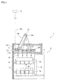
- a spinning winder 1 includes a winding unit 3, a frame-shaped frame 14 provided to be further than the winding unit 3 for the viewer of Fig. 1 , two godet rollers 11 and 12 that receive a plurality of yarns 10 supplied from a spinning machine 2, and a plurality of fulcrum guides 13 (distribution guides) that distribute the yarns 10 wound on the godet roller 12 on the downstream side to bobbins B attached to a bobbin holder 7 of the winding unit 3, respectively, and function as fulcrums at the time of traversal by a traverse guide 8.
- the spinning winder 1 serially supplies the yarns 10, which are spun out from the spinning machine 2, to the winding unit 3 below by the two godet rollers 11 and 12 while aligning the yarns 10 in the directions orthogonal to the plane of Fig. 1 , and winds the yarns 10 by the winding unit 3.
- the winding unit 3 will be discussed.
- the winding unit 3 is provided below the spinning machine 2, and forms packages P by winding the yarns 10 supplied from the spinning machine 2 via the two godet rollers 11 and 12 onto the respective bobbins B.
- This winding unit 3 includes components such as: a main body frame 5; a disc-shaped turret 6 which is rotatably provided on the main body frame 5, two bobbin holders 7 (winding spindles) each of which is supported by the turret 6 at one end and to each of which a plurality of bobbins B are attached in series along an axis 7a; a plurality of traverse guides 8 that are provided above the respective bobbins B attached to the bobbin holder 7 and traverse the yarns 10 that are to be wound onto the bobbins B; and a contact roller 9 which is arranged to be vertically movable with respect to the main body frame 5 and contacts or move away from the bobbins B attached to the bobbin holder 7.
- the winding unit 3 rotates the bobbin holder 7 by an unillustrated drive motor so as to rotate the bobbins B attached to this bobbin holder 7 and winds the yarns 10 onto the respective rotating bobbins B.
- the yarn 10 wound onto the bobbin B is, immediately before being wound, traversed in the axial directions of the bobbin B by the traverse guide 8 which is capable of reciprocating in the axial directions of the bobbin B, with the later-described fulcrum guide 13 functioning as a fulcrum.
- the contact roller 9 rotates while imparting a predetermined contact pressure to the package P when the yarn is wound onto the bobbin B, so that the package P is properly shaped.
- the two godet rollers 11 and 12 are rotatably supported by the frame 14, above the main body frame 5 of the winding unit 3.
- the axes 11a and 12a of these rollers are orthogonal to the axis 7a of the bobbin holder 7.
- the godet rollers 11 and 12 are drive rollers driven by an unillustrated drive motor.
- the godet roller 11 is provided immediately below the spinning machine 2.
- the godet roller 12 is provided above the godet roller 11 and is deviated from the godet roller 11 in the axial direction of the bobbin holder 7.
- the godet roller 12 is movable, by an elevation mechanism 16 such as a linear motor, between a yarn winding position (indicated by full lines in Fig. 1 ) above the substantial center of the fulcrum guides 13 in their alignment directions and a yarn threading position (indicated by two-dot chain lines in Fig. 1 ) which is close to the godet roller 11 below as compared to the yarn winding position.
- an elevation mechanism 16 such as a linear motor
- the fulcrum guides 13 are provided below the downstream-side godet roller 12 at the yarn winding position and above the traverse guides 8. These fulcrum guides 13 are aligned immediately above the respective traverse guides 8 and the respective bobbins B attached to the bobbin holder 7, along the axis 7a of the bobbin holder 7 and at the same intervals as the centers of the respective bobbins B in the axial directions.
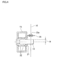
- Each of the fulcrum guides 13 is, as shown in Fig. 2 to Fig. 4 , a column with a radius R of not shorter than 3mm and not longer than 8mm and extends in horizontal directions orthogonal to the axial directions of the bobbin holder 7 (i.e., in predetermined directions intersecting with the axis of the bobbin holder 7).
- the yarn 10 supplied from the godet roller 12 is threaded on the outer circumference of the fulcrum guide 13.
- the curvature radius of the fulcrum guide 13 is not shorter than 3mm and not longer than 8mm at the sliding surface on which the yarn 10 slides.
- the fulcrum guides 13 are made of, for example, a ceramic material, and are attached to the guide supporting members 21 at the base end portions, as shown in Fig. 2 to Fig. 4 . Furthermore, on guide supporting members 21 corresponding to two neighboring fulcrum guides 13 among the fulcrum guides 13, a belt 22 is mounted. In addition to this, a pulley 23 is provided to oppose a guide supporting member 21 neighboring a guide supporting member 21 corresponding to one of the outermost two fulcrum guides 13 (i.e., the rightmost guide supporting member 21 in Fig. 3 ), and a belt 22 is also mounted on the guide supporting member 21 and the pulley 23. The pulley 23 is connected to a motor 24.
- the guide supporting members 21 connected to one another by the belts 22 and the fulcrum guides 13 attached to the guide supporting members 21 rotate about their axes.
- the sliding position at which the yarn 10 slides on each fulcrum guide 13 is changed. That is to say, according to the present embodiment, the belts 22, the pulley 23, and the motor 24 constitute a guide rotation mechanism of the present invention, which constitutes a sliding position change mechanism of the present invention.
- the outer circumference of the fulcrum guide 13, on which the yarn 10 slides is treated to facilitate smooth sliding of the yarn 10, in order to reduce the friction with the yarn 10.
- the treatment on the fulcrum guide 13 becomes ineffective after the yarn 10 slides on a particular part of the outer circumference of the fulcrum guide 13 for a long time.
- the present embodiment is arranged, as described above, so that the sliding position between the fulcrum guide 13 and the yarn 10 is changeable by rotating the fulcrum guide 13, with the result that the life of the fulcrum guide 13 is extended.
- the sliding position between the fulcrum guide 13 and the yarn 10 is changed in such a way that, for example, the fulcrum guide 13 is rotated for a predetermined angle each time the spinning winder 1 is driven for a predetermined period.
- the guide supporting members 21 and the pulley 23 attached to the motor 24 are connected with one another by the belts 22. For this reason, as the motor 24 is driven, the pulley 23 and the fulcrum guides 13 rotate and hence the sliding positions between the yarns 10 and the fulcrum guides 13 are changed at once.
- a restraining guide 25 is provided immediately above the respective fulcrum guides 13.
- the restraining guide 25 extends along the axial directions of the bobbin holder 7 and has a slit 25a which is open at the edge which is on the back side in Fig. 2 .
- the yarn 10 threaded on the fulcrum guide 13 is arranged to pass through the slit 25a.
- the walls of the slit 25a therefore restrain the yarn 10 from moving in the axial directions (predetermined directions) of the fulcrum guide 13. This makes it possible to prevent the yarn 10 from dropping off from the fulcrum guide 13.
- the yarns 10 supplied from the spinning machine 2 are transported downward and then wound onto the godet roller 11 to be aligned along the axis 11a. Thereafter, the yarns 10 wound onto the godet roller 11 obliquely run while being kept to be in parallel to each other, and are passed to the godet roller 12 which is at the yarn winding position.
- the yarns 10 wound onto the godet roller 12 are threaded on the respective fulcrum guides 13, are bended at the fulcrum guides 13, and are transported downward toward the winding unit 3.
- the yarn 10 When the yarn 10 is bended at the fulcrum guide 13, as shown in Fig. 5 , the yarn 10 receives a contact pressure F from the fulcrum guide 13. This contact pressure increases as the winding angle ⁇ of the yarn 10 with respect to the fulcrum guide 13 (i.e., bending angle of the yarn 10) increases. The higher the contact pressure F is, the more the yarn 10 is damaged.
- the winding angle ⁇ is decreased as the position of the godet roller 12 that supplies the yarn 10 to the fulcrum guide 13 is arranged to be higher. For this reason, when the winding angle ⁇ is decreased (to not larger than 15 degrees, for example) by arranging the godet roller 12 at a high position, the contact pressure F that the yarn 10 receives from the fulcrum guide 13 is reduced and the damage on the yarn 10 is reduced. However, arranging the godet roller 12 at a high position leads to the increase in size of the apparatus.
- the number of yarns 10 supplied from the spinning machine 2 is large in recent apparatuses.
- the fulcrum guides 13 on the outer sides in the axial directions of the bobbin holder 7 are significantly far from the godet roller 12, and hence the winding angle ⁇ of the yarn 10 is large at each of these fulcrum guides 13 on the outer sides.
- the decrease in the winding angle ⁇ is achieved by providing the godet roller 12 at a high position, the position of the godet roller 12 gets higher as the number of the yarns 10 increases, with the result that the apparatus is significantly enlarged in size.
- the curvature radius of the fulcrum guide 13 with respect to the yarn 10 is long because the fulcrum guide 13 is arranged to be a column whose outer circumference functions as a sliding surface on which the yarn 10 slides so that the contact pressure F that the yarn 10 receives from the fulcrum guide 13 is small.
- the part of the yarn 10 sliding on the fulcrum guide 13 is elongated as the radius R of the fulcrum guide 13 (i.e., the curvature radius of the yarn 10 at the sliding surface) increases. For this reason, when the radius R of the fulcrum guide 13 is too long, the damage on the yarn 10 on account of the sliding on the fulcrum guide 13 is serious.
- the minimization of the damage on the yarn 10 requires the radius R of the fulcrum guide 13 (i.e., the curvature radius of the yarn 10 at the sliding surface) to fall within a suitable range in consideration of the contact pressure F applied from the fulcrum guide 13 to the yarn 10 and the length of the part of the yarn 10 sliding on the fulcrum guide 13.
- the present embodiment is arranged so that the radius R of the column-shaped fulcrum guide 13 is arranged to be not shorter than 3mm and not longer than 8mm in order to minimize the damage on the yarn 10. With this, even if the godet roller 12 is positioned low and the winding angle ⁇ is large, the damage on the yarn 10 at the fulcrum guide 13 is minimized as described below.
- Fig. 6 shows a result of measurement of the yarn property of the yarn 10 on the downstream of the fulcrum guide 13, when the yarn Y supplied from the godet roller 12 was distributed by using fulcrum guides 13 with various radii R.
- the yarn property indicates a ratio between a tensile stress at break of the yarn 10 in case where the yarn 10 is not bended is stretched and a tensile stress at break of the yarn 10 in case where the yarn 10 which is bended is stretched.
- the yarn 10 is a multi-filament yarn which is a polyester FDY of 150 denier, and the winding angle ⁇ of the yarn 10 at the fulcrum guide 13 is 30 degrees, the running speed of the yarn 10 is 4800m/min, and the yarn tension in the part upstream of the fulcrum guide 13 is 0.25gr/de.
- the yarn property is preferably not lower than 90%. In this regard, according to the result shown in Fig. 6 , it is understood that the yarn property of not lower than 90% is achieved when the radius R of the fulcrum guide 13 falls within the range of 3mm to 8mm.
- Fig. 6 shows the case where the winding angle ⁇ is 30 degrees.
- the damage on the yarn 10 is smaller as compared to the case where the winding angle ⁇ is 30 degrees on condition that the radius R of the fulcrum guide 13 is identical, because the contact pressure F is small and the part where the yarn 10 slides on the fulcrum guide 13 is short as compared to the case where the winding angle ⁇ is 30 degrees. Therefore, even if the winding angle ⁇ is smaller than 30 degrees, the yarn property of not lower than 90% is achieved by arranging the radius R of the fulcrum guide 13 to fall within the range of 3mm to 8mm. Furthermore, even if the type, thickness, running speed or the like of the yarn 10 are different from those in the example above, it is assumed that a yarn property similar to that of the measurement above is achieved when the winding angle ⁇ is 30 degrees.
- a single belt may be mounted over all guide supporting members 21 and the pulley 23.
- a motor is individually provided for each fulcrum guide 13 to allow each fulcrum guide 13 to individually rotate.
- changing the sliding position between the fulcrum guide 13 and the yarn 10 may be achieved by a solution other than the rotation of the fulcrum guide 13.
- a modification modification 1
- an air cylinder 30 is provided on the side opposite to the leading end of the fulcrum guide 13, and a piston 31 of the air cylinder 30 is attached to an end portion of the fulcrum guide 13 which portion is opposite to the leading end.
- the piston 31 and the fulcrum guide 13 move together along the axial directions of the fulcrum guide 13. More specifically, the fulcrum guide 13 moves toward the leading end side in the axial directions when the air pressure in the internal space 32 is increased, or moves toward the base end side when the air pressure in the internal space 32 is decreased.
- the air cylinder 30 is equivalent to a guide movement mechanism of the present invention, which is a part of the sliding position change mechanism of the present invention.
- the fulcrum guide 13 While in the modification 1 the fulcrum guide 13 is moved in its axial directions by the air cylinder 30, the fulcrum guide may be moved in its axial directions by a hydraulic cylinder or other mechanisms.
- the embodiment has only the mechanism for rotating the fulcrum guide 13 (i.e., belt 22, pulley 23, and motor 24) whereas the modification 1 has only the mechanism for moving the fulcrum guide 13 in its axial directions (i.e., air cylinder 30).
- both of these two mechanisms may be concurrently provided.
- Such an arrangement further elongates the life of the fulcrum guide 13.
- the arrangement to prevent the yarn 10 from dropping off from the fulcrum guide 13 is not limited to this.
- the prevention of dropping off of the yarn 10 from the fulcrum guide 13 may be achieved by other arrangements, e.g., the fulcrum guide 13 is arranged to be wide in diameter at the leading end.
- the fulcrum guide 13 may extend in directions which intersect the axial directions of the bobbin holder 7 and are inclined with respect to the directions orthogonal to the axial directions of the bobbin holder 7.
- the fulcrum guide may not be column-shaped but have a different shape in which the curvature radius at the sliding surface on which the yarn 10 slides is not shorter than 3mm and not longer than 8mm.
- the curvature radius of the fulcrum guide at the sliding surface on which the yarn 10 slides may not be constant but be different at different parts.
Landscapes
- Spinning Methods And Devices For Manufacturing Artificial Fibers (AREA)
- Forwarding And Storing Of Filamentary Material (AREA)
- Guides For Winding Or Rewinding, Or Guides For Filamentary Materials (AREA)
Abstract
Description
- The present invention relates to a spinning winder for winding yarns spun out from a spinning unit onto bobbins.
- A spinning winder recited in Patent Literature 1 (Japanese Unexamined Patent Publication No.
2000-272835 - In this spinning winder of
Patent Literature 1, because the yarns are bended at the distribution guides as described above, the contact pressure applied from the distribution guide to the yarn is high when the bending angle (winding angle) of the yarn is large, resulting in serious damage on the yarn. In this regard, while the bending angle is small when the godet rollers are highly positioned, the apparatus becomes large in size as the godet rollers are highly positioned. In the meanwhile, when a large number of yarns are spun out from the spinning machine and a lot of distribution guides are aligned along the axial directions of the bobbin holder, the distribution guides provided on the outer sides in the axial directions of the bobbin holder are remote from the godet rollers, and the bending angle of the yarn is large at such outer distribution guides. In this regard, in order to keep the bending angle of the yarn to be small, the positions of the godet rollers are required to be higher as the number of yarns spun out from the spinning unit increases. As such, the increase in size of the apparatus becomes a serious problem. - To solve this problem, a winding device recited in Patent Literature 2 (PCT Application Entering National Phase in Japan No.
2005-534825 - The winding device of
Patent Literature 2, however, is disadvantageous in that, when the distribution guides are rotatably supported, because the distribution guides rapidly rotate as the yarns rapidly run, frequent maintenance is required to restrain the components such as bearings provided between the distribution guides and their supporting axes from being worn away. - On the other hand, when the distribution guides are rotated by a driving unit, each distribution guide receives torque from the driving unit and hence a force generated by the torque is exerted to the yarn contacting the distribution guide. Because the magnitude of the torque that the distribution guide receives from the driving unit is determined by the number of revolution of the distribution guide, more or less the same degree of force is exerted to the yarn, irrespective of the thickness or the like of the yarn. Therefore, a large force is exerted from the distribution guide to the yarn when the yarn is thin, and the yarn may be seriously damaged.
- An object of the present invention is to provide a spinning winder in which damage on a bended yarn is minimized irrespective of the thickness of the yarn when the bending angle of the yarn is large at a distribution guide and frequent maintenance is unnecessary.
- A spinning winder according to the first aspect of the invention includes: a winding spindle to which a plurality of bobbins are attached in series along an axis and which winds a plurality of yarns spun out from a spinning unit onto the bobbins; and a plurality of distribution guides that bend the yarns spun out from the spinning unit and distribute the yarns to the respective bobbins attached to the winding spindle, curvature radii of the distribution guides at sliding surfaces on which the yarns slide being not shorter than 3mm and not longer than 8mm.
- According to the present invention, the damage on the yarn is restrained even if the yarn is bended to some degree at the distribution guide, because the curvature radius of the distribution guide at the sliding surface on which the yarn slides is arranged to be within the range of 3mm to 8mm. This makes it possible to increase the bending angle of the yarn at the distribution guide while restraining the height of the spinning winder. Furthermore, because the distribution guide does not rotate while the yarn is running, the yarn is not damaged by a large force exerted from the rotating distribution guide to the yarn, and frequent maintenance of the distribution guide is unnecessary.
- According to the second aspect, the spinning winder of the first aspect is arranged so that a bending angle of each of the yarns at each of the distribution guides is not larger than 30 degrees.
- According to the present invention, when the bending angle of the yarn at the distribution guide is 30 degrees or lower, the damage on the yarn is restrained by keeping the curvature radius of the distribution guide at the sliding surface on which the yarn slides to be not shorter than 3mm and not longer than 8mm.
- According to the third aspect, the spinning winder of the second aspect further includes a sliding position change mechanism for changing sliding positions where the yarns slide on the corresponding distribution guides.
- After the yarn slides on a particular part of the outer circumference of the distribution guide for a long time, the treatment on that part of the distribution guide for facilitating smooth sliding of the yarn becomes ineffective. In this regard, the life of the distribution guide is elongated according to the present invention because the sliding position between the distribution guide and the yarn is changeable.
- According to the fourth aspect, the spinning winder of the third aspect is arranged so that the distribution guides are columns having outer circumferences on which the yarns slide, and the sliding position change mechanism is provided with a guide rotation mechanism that changes the sliding positions by rotating the distribution guides about their axes.
- According to the present invention, when the distribution guide is column-shaped, the sliding position between the distribution guide and the yarn is changed by rotating the distribution guide about its axis.
- According to the fifth aspect, the spinning winder of the fourth aspect is arranged so that the guide rotation mechanism includes: an endless belt that is mounted on the distribution guides to connect the distribution guides with one another; and a belt driving unit for driving the belts.
- According to the present invention, the sliding positions between the distribution guides connected with one another by the belt and the yarns are changed altogether by simply driving a single belt driving unit.
- According to the sixth aspect, the spinning winder of one of the first to fifth aspects is arranged so that the distribution guides extend in a predetermined direction that intersects with axial directions of the winding spindle, and the sliding position change mechanism is provided with a guide movement mechanism that changes the sliding positions by moving the distribution guides in the predetermined direction.
- According to the present invention, when the distribution guide extends in the predetermined direction intersecting with the axial directions of the winding spindle, the sliding position between the distribution guide and the yarn is changed by moving the distribution guide in the predetermined direction.
- According to the seventh aspect, the spinning winder of one of first to sixth aspects further includes a restraining means for restraining the yarns threaded on the distribution guides from moving in directions orthogonal to a running direction of the yarns at parts where the yarns slides on the distribution guides.
- According to the present invention, it is possible to prevent the yarn from dropping off from the distribution guide.
- According to the present invention, the damage on the yarn is restrained even if the yarn is bended to some degree at the distribution guide, because the curvature radius of the distribution guide at the sliding surface on which the yarn slides is arranged to be within the range of 3mm to 8mm. This makes it possible to increase the bending angle of the yarn at the distribution guide while restraining the height of the spinning winder. Furthermore, because the distribution guide does not rotate while the yarn is running, the yarn is not damaged by a large force exerted from the rotating distribution guide to the yarn, and frequent maintenance of the distribution guide is unnecessary.
-
-
Fig. 1 is a schematic view of a spinning winder according to an embodiment of the present invention. -
Fig. 2 is a perspective view of the fulcrum guide ofFig. 1 and its surroundings. -
Fig. 3 shows the inside of the fulcrum guide ofFig. 2 from above. -
Fig. 4 is a cross section ofFig. 3 taken at IV-IV line. -
Fig. 5 shows the winding angle of the yarn at the fulcrum guide, the contact pressure that the yarn receives from the fulcrum guide, or the like. -
Fig. 6 shows the measurement result of the physical property of the yarn when the yarn is distributed by fulcrum guides with various radii. -
Fig. 7 relates to amodification 1 and is equivalent toFig. 4 . - The following will describe a preferred embodiment of the present invention.
- A spinning
winder 1 includes a winding unit 3, a frame-shaped frame 14 provided to be further than the winding unit 3 for the viewer ofFig. 1 , twogodet rollers yarns 10 supplied from aspinning machine 2, and a plurality of fulcrum guides 13 (distribution guides) that distribute theyarns 10 wound on thegodet roller 12 on the downstream side to bobbins B attached to abobbin holder 7 of the winding unit 3, respectively, and function as fulcrums at the time of traversal by atraverse guide 8. - As shown in
Fig. 1 , the spinningwinder 1 serially supplies theyarns 10, which are spun out from thespinning machine 2, to the winding unit 3 below by the twogodet rollers yarns 10 in the directions orthogonal to the plane ofFig. 1 , and winds theyarns 10 by the winding unit 3. - The winding unit 3 will be discussed. The winding unit 3 is provided below the
spinning machine 2, and forms packages P by winding theyarns 10 supplied from thespinning machine 2 via the twogodet rollers - This winding unit 3 includes components such as: a
main body frame 5; a disc-shaped turret 6 which is rotatably provided on themain body frame 5, two bobbin holders 7 (winding spindles) each of which is supported by theturret 6 at one end and to each of which a plurality of bobbins B are attached in series along anaxis 7a; a plurality oftraverse guides 8 that are provided above the respective bobbins B attached to thebobbin holder 7 and traverse theyarns 10 that are to be wound onto the bobbins B; and acontact roller 9 which is arranged to be vertically movable with respect to themain body frame 5 and contacts or move away from the bobbins B attached to thebobbin holder 7. - The winding unit 3 rotates the
bobbin holder 7 by an unillustrated drive motor so as to rotate the bobbins B attached to thisbobbin holder 7 and winds theyarns 10 onto the respective rotating bobbins B. In this regard, theyarn 10 wound onto the bobbin B is, immediately before being wound, traversed in the axial directions of the bobbin B by thetraverse guide 8 which is capable of reciprocating in the axial directions of the bobbin B, with the later-describedfulcrum guide 13 functioning as a fulcrum. In this way, a package P is formed. Thecontact roller 9 rotates while imparting a predetermined contact pressure to the package P when the yarn is wound onto the bobbin B, so that the package P is properly shaped. - As shown in
Fig. 1 , the twogodet rollers frame 14, above themain body frame 5 of the winding unit 3. Theaxes 11a and 12a of these rollers are orthogonal to theaxis 7a of thebobbin holder 7. Thegodet rollers godet roller 11 is provided immediately below thespinning machine 2. Thegodet roller 12 is provided above thegodet roller 11 and is deviated from thegodet roller 11 in the axial direction of thebobbin holder 7. - The
godet roller 12 is movable, by anelevation mechanism 16 such as a linear motor, between a yarn winding position (indicated by full lines inFig. 1 ) above the substantial center of thefulcrum guides 13 in their alignment directions and a yarn threading position (indicated by two-dot chain lines inFig. 1 ) which is close to thegodet roller 11 below as compared to the yarn winding position. - The
fulcrum guides 13 are provided below the downstream-side godet roller 12 at the yarn winding position and above thetraverse guides 8. Thesefulcrum guides 13 are aligned immediately above therespective traverse guides 8 and the respective bobbins B attached to thebobbin holder 7, along theaxis 7a of thebobbin holder 7 and at the same intervals as the centers of the respective bobbins B in the axial directions. - Each of the
fulcrum guides 13 is, as shown inFig. 2 to Fig. 4 , a column with a radius R of not shorter than 3mm and not longer than 8mm and extends in horizontal directions orthogonal to the axial directions of the bobbin holder 7 (i.e., in predetermined directions intersecting with the axis of the bobbin holder 7). Theyarn 10 supplied from thegodet roller 12 is threaded on the outer circumference of thefulcrum guide 13. In other words, the curvature radius of thefulcrum guide 13 is not shorter than 3mm and not longer than 8mm at the sliding surface on which theyarn 10 slides. - In addition to the above, the fulcrum guides 13 are made of, for example, a ceramic material, and are attached to the
guide supporting members 21 at the base end portions, as shown inFig. 2 to Fig. 4 . Furthermore, onguide supporting members 21 corresponding to two neighboring fulcrum guides 13 among the fulcrum guides 13, abelt 22 is mounted. In addition to this, apulley 23 is provided to oppose aguide supporting member 21 neighboring aguide supporting member 21 corresponding to one of the outermost two fulcrum guides 13 (i.e., the rightmostguide supporting member 21 inFig. 3 ), and abelt 22 is also mounted on theguide supporting member 21 and thepulley 23. Thepulley 23 is connected to amotor 24. As thepulley 23 is rotated by driving themotor 24, theguide supporting members 21 connected to one another by thebelts 22 and the fulcrum guides 13 attached to theguide supporting members 21 rotate about their axes. As each fulcrum guides 13 rotates, the sliding position at which theyarn 10 slides on eachfulcrum guide 13 is changed. That is to say, according to the present embodiment, thebelts 22, thepulley 23, and themotor 24 constitute a guide rotation mechanism of the present invention, which constitutes a sliding position change mechanism of the present invention. - In the meanwhile, the outer circumference of the
fulcrum guide 13, on which theyarn 10 slides, is treated to facilitate smooth sliding of theyarn 10, in order to reduce the friction with theyarn 10. However, the treatment on thefulcrum guide 13 becomes ineffective after theyarn 10 slides on a particular part of the outer circumference of thefulcrum guide 13 for a long time. - In this regard, the present embodiment is arranged, as described above, so that the sliding position between the
fulcrum guide 13 and theyarn 10 is changeable by rotating thefulcrum guide 13, with the result that the life of thefulcrum guide 13 is extended. The sliding position between thefulcrum guide 13 and theyarn 10 is changed in such a way that, for example, thefulcrum guide 13 is rotated for a predetermined angle each time thespinning winder 1 is driven for a predetermined period. - In addition to the above, the
guide supporting members 21 and thepulley 23 attached to themotor 24 are connected with one another by thebelts 22. For this reason, as themotor 24 is driven, thepulley 23 and the fulcrum guides 13 rotate and hence the sliding positions between theyarns 10 and the fulcrum guides 13 are changed at once. - In addition to the above, immediately above the respective fulcrum guides 13, a restraining
guide 25 is provided. The restrainingguide 25 extends along the axial directions of thebobbin holder 7 and has aslit 25a which is open at the edge which is on the back side inFig. 2 . Theyarn 10 threaded on thefulcrum guide 13 is arranged to pass through theslit 25a. The walls of theslit 25a therefore restrain theyarn 10 from moving in the axial directions (predetermined directions) of thefulcrum guide 13. This makes it possible to prevent theyarn 10 from dropping off from thefulcrum guide 13. - In the
spinning winder 1 arranged as described above, as shown inFig. 1 , theyarns 10 supplied from the spinningmachine 2 are transported downward and then wound onto thegodet roller 11 to be aligned along the axis 11a. Thereafter, theyarns 10 wound onto thegodet roller 11 obliquely run while being kept to be in parallel to each other, and are passed to thegodet roller 12 which is at the yarn winding position. Theyarns 10 wound onto thegodet roller 12 are threaded on the respective fulcrum guides 13, are bended at the fulcrum guides 13, and are transported downward toward the winding unit 3. - When the
yarn 10 is bended at thefulcrum guide 13, as shown inFig. 5 , theyarn 10 receives a contact pressure F from thefulcrum guide 13. This contact pressure increases as the winding angle θ of theyarn 10 with respect to the fulcrum guide 13 (i.e., bending angle of the yarn 10) increases. The higher the contact pressure F is, the more theyarn 10 is damaged. - In the meanwhile, the winding angle θ is decreased as the position of the
godet roller 12 that supplies theyarn 10 to thefulcrum guide 13 is arranged to be higher. For this reason, when the winding angle θ is decreased (to not larger than 15 degrees, for example) by arranging thegodet roller 12 at a high position, the contact pressure F that theyarn 10 receives from thefulcrum guide 13 is reduced and the damage on theyarn 10 is reduced. However, arranging thegodet roller 12 at a high position leads to the increase in size of the apparatus. - In the meanwhile, the number of
yarns 10 supplied from the spinningmachine 2 is large in recent apparatuses. In this regard, when a lot of fulcrum guides 13 are provided for this reason, the fulcrum guides 13 on the outer sides in the axial directions of thebobbin holder 7 are significantly far from thegodet roller 12, and hence the winding angle θ of theyarn 10 is large at each of these fulcrum guides 13 on the outer sides. On this account, when the decrease in the winding angle θ is achieved by providing thegodet roller 12 at a high position, the position of thegodet roller 12 gets higher as the number of theyarns 10 increases, with the result that the apparatus is significantly enlarged in size. - In this regard, according to the present embodiment, even if the winding angle θ is large (e.g., about 30 degrees), the curvature radius of the
fulcrum guide 13 with respect to theyarn 10 is long because thefulcrum guide 13 is arranged to be a column whose outer circumference functions as a sliding surface on which theyarn 10 slides so that the contact pressure F that theyarn 10 receives from thefulcrum guide 13 is small. - However, provided that the winding angle θ is the same, the part of the
yarn 10 sliding on thefulcrum guide 13 is elongated as the radius R of the fulcrum guide 13 (i.e., the curvature radius of theyarn 10 at the sliding surface) increases. For this reason, when the radius R of thefulcrum guide 13 is too long, the damage on theyarn 10 on account of the sliding on thefulcrum guide 13 is serious. - That is to say, when the winding angle θ of the
yarn 10 at thefulcrum guide 13 is arranged to be large, the minimization of the damage on theyarn 10 requires the radius R of the fulcrum guide 13 (i.e., the curvature radius of theyarn 10 at the sliding surface) to fall within a suitable range in consideration of the contact pressure F applied from thefulcrum guide 13 to theyarn 10 and the length of the part of theyarn 10 sliding on thefulcrum guide 13. - In this regard, the present embodiment is arranged so that the radius R of the column-shaped
fulcrum guide 13 is arranged to be not shorter than 3mm and not longer than 8mm in order to minimize the damage on theyarn 10. With this, even if thegodet roller 12 is positioned low and the winding angle θ is large, the damage on theyarn 10 at thefulcrum guide 13 is minimized as described below. - Now, an example of the present invention will be described with reference to
Fig. 6. Fig. 6 shows a result of measurement of the yarn property of theyarn 10 on the downstream of thefulcrum guide 13, when the yarn Y supplied from thegodet roller 12 was distributed by using fulcrum guides 13 with various radii R. Note that, the yarn property indicates a ratio between a tensile stress at break of theyarn 10 in case where theyarn 10 is not bended is stretched and a tensile stress at break of theyarn 10 in case where theyarn 10 which is bended is stretched. The higher the yarn property is, the less the damage on theyarn 10 at thefulcrum guide 13 is. Furthermore, in the measurement shown inFig. 6 , theyarn 10 is a multi-filament yarn which is a polyester FDY of 150 denier, and the winding angle θ of theyarn 10 at thefulcrum guide 13 is 30 degrees, the running speed of theyarn 10 is 4800m/min, and the yarn tension in the part upstream of thefulcrum guide 13 is 0.25gr/de. To make sure that theyarn 10 wound onto the bobbin B is durable in practical use, the yarn property is preferably not lower than 90%. In this regard, according to the result shown inFig. 6 , it is understood that the yarn property of not lower than 90% is achieved when the radius R of thefulcrum guide 13 falls within the range of 3mm to 8mm. -
Fig. 6 shows the case where the winding angle θ is 30 degrees. In this regard, when the winding angle θ is smaller than 30 degrees, the damage on theyarn 10 is smaller as compared to the case where the winding angle θ is 30 degrees on condition that the radius R of thefulcrum guide 13 is identical, because the contact pressure F is small and the part where theyarn 10 slides on thefulcrum guide 13 is short as compared to the case where the winding angle θ is 30 degrees. Therefore, even if the winding angle θ is smaller than 30 degrees, the yarn property of not lower than 90% is achieved by arranging the radius R of thefulcrum guide 13 to fall within the range of 3mm to 8mm. Furthermore, even if the type, thickness, running speed or the like of theyarn 10 are different from those in the example above, it is assumed that a yarn property similar to that of the measurement above is achieved when the winding angle θ is 30 degrees. - Now, various modifications of the present embodiment will now be described. It is noted that the description of the same arrangements as in the embodiment will be omitted.
- In the embodiment above, neighboring two guide supporting members 21 (fulcrum guides 13) are connected with each other by the
belt 22, the outermostguide supporting member 21 and thepulley 23 connected to themotor 24 are connected with each other by thebelt 22, and the sliding positions between the fulcrum guides 13 and theyarns 10 are changed altogether by rotating themotor 24. This arrangement, however, is not prerequisite. - For example, a single belt may be mounted over all
guide supporting members 21 and thepulley 23. Alternatively, a motor is individually provided for each fulcrum guide 13 to allow each fulcrum guide 13 to individually rotate. - In addition to the above, changing the sliding position between the
fulcrum guide 13 and theyarn 10 may be achieved by a solution other than the rotation of thefulcrum guide 13. According to a modification (modification 1), as shown inFig. 7 , anair cylinder 30 is provided on the side opposite to the leading end of thefulcrum guide 13, and apiston 31 of theair cylinder 30 is attached to an end portion of thefulcrum guide 13 which portion is opposite to the leading end. As an air pressure in theinternal space 32 of theair cylinder 30 is changed by using an unillustrated pump or the like, thepiston 31 and thefulcrum guide 13 move together along the axial directions of thefulcrum guide 13. More specifically, thefulcrum guide 13 moves toward the leading end side in the axial directions when the air pressure in theinternal space 32 is increased, or moves toward the base end side when the air pressure in theinternal space 32 is decreased. - The sliding position between the
fulcrum guide 13 and theyarn 10 is changed by moving thefulcrum guide 13 along the axial directions as above, and this makes it possible to elongate the life of thefulcrum guide 13. That is to say, in themodification 1, theair cylinder 30 is equivalent to a guide movement mechanism of the present invention, which is a part of the sliding position change mechanism of the present invention. - While in the
modification 1 thefulcrum guide 13 is moved in its axial directions by theair cylinder 30, the fulcrum guide may be moved in its axial directions by a hydraulic cylinder or other mechanisms. - In addition to the above, as the mechanism for changing the sliding position between the
fulcrum guide 13 and theyarn 10, the embodiment has only the mechanism for rotating the fulcrum guide 13 (i.e.,belt 22,pulley 23, and motor 24) whereas themodification 1 has only the mechanism for moving thefulcrum guide 13 in its axial directions (i.e., air cylinder 30). In this regard, both of these two mechanisms may be concurrently provided. Such an arrangement further elongates the life of thefulcrum guide 13. - In addition to the above, while in the example above the mechanism for changing the sliding position between the
fulcrum guide 13 and theyarn 10 is provided, such a mechanism may not be provided. - In addition to the above, while in the embodiment above the restraining
guide 25 is provided above thefulcrum guide 13 to prevent theyarn 10 from moving along the axial directions of thefulcrum guide 13 and dropping off from thefulcrum guide 13, the arrangement to prevent theyarn 10 from dropping off from thefulcrum guide 13 is not limited to this. For example, the prevention of dropping off of theyarn 10 from thefulcrum guide 13 may be achieved by other arrangements, e.g., thefulcrum guide 13 is arranged to be wide in diameter at the leading end. - In addition to the above, when the
fulcrum guide 13 is sufficiently long in the axial directions and theyarn 10 is unlikely to drop off from thefulcrum guide 13 even if theyarn 10 moves in the axial directions of thefulcrum guide 13, the above-described arrangement for preventing theyarn 10 from dropping off from thefulcrum guide 13 may be unnecessary. - While in the embodiment above the
fulcrum guide 13 extends in the directions orthogonal to the axial directions of thebobbin holder 7 and is a column whose outer circumference functions as the sliding surface on which theyarn 10 slides, thefulcrum guide 13 may extend in directions which intersect the axial directions of thebobbin holder 7 and are inclined with respect to the directions orthogonal to the axial directions of thebobbin holder 7. Furthermore, the fulcrum guide may not be column-shaped but have a different shape in which the curvature radius at the sliding surface on which theyarn 10 slides is not shorter than 3mm and not longer than 8mm. Furthermore, the curvature radius of the fulcrum guide at the sliding surface on which theyarn 10 slides may not be constant but be different at different parts.
Claims (7)
- A spinning winder comprising:a winding spindle to which a plurality of bobbins are attached in series along an axis and which winds a plurality of yarns spun out from a spinning unit onto the bobbins; anda plurality of distribution guides that bend the yarns spun out from the spinning unit and distribute the yarns to the respective bobbins attached to the winding spindle,curvature radii of the distribution guides at sliding surfaces on which the yarns slide being not shorter than 3mm and not longer than 8mm.
- The spinning winder according to claim 1, wherein, a bending angle of each of the yarns at each of the distribution guides is not larger than 30 degrees.
- The spinning winder according to claim 1 or 2, further comprising:a sliding position change mechanism for changing sliding positions where the yarns slide on the corresponding distribution guides.
- The spinning winder according to claim 3, wherein, the distribution guides are columns having outer circumferences on which the yarns slide, and
the sliding position change mechanism is provided with a guide rotation mechanism that changes the sliding positions by rotating the distribution guides about their axes. - The spinning winder according to claim 4, wherein, the guide rotation mechanism includes:an endless belt that is mounted on the distribution guides to connect the distribution guides with one another; anda belt driving unit for driving the belt.
- The spinning winder according to any one of claims 1 to 5, wherein,
the distribution guides extend in a predetermined direction that intersects with axial directions of the winding spindle, and
the sliding position change mechanism is provided with a guide movement mechanism that changes the sliding positions by moving the distribution guides in the predetermined direction. - The spinning winder according to any one of claims 1 to 6, further comprising:a restraining means for restraining the yarns threaded on the distribution guides from moving in directions orthogonal to a running direction of the yarns at parts where the yarns slides on the distribution guides.
Applications Claiming Priority (1)
| Application Number | Priority Date | Filing Date | Title |
|---|---|---|---|
| JP2011160825A JP5711062B2 (en) | 2011-07-22 | 2011-07-22 | Spinning winder |
Publications (3)
| Publication Number | Publication Date |
|---|---|
| EP2548830A2 true EP2548830A2 (en) | 2013-01-23 |
| EP2548830A3 EP2548830A3 (en) | 2013-11-13 |
| EP2548830B1 EP2548830B1 (en) | 2014-08-13 |
Family
ID=46331092
Family Applications (1)
| Application Number | Title | Priority Date | Filing Date |
|---|---|---|---|
| EP20120173797 Active EP2548830B1 (en) | 2011-07-22 | 2012-06-27 | Spinning winder |
Country Status (3)
| Country | Link |
|---|---|
| EP (1) | EP2548830B1 (en) |
| JP (1) | JP5711062B2 (en) |
| CN (1) | CN102888667B (en) |
Cited By (4)
| Publication number | Priority date | Publication date | Assignee | Title |
|---|---|---|---|---|
| EP3988487A1 (en) * | 2020-10-23 | 2022-04-27 | TMT Machinery, Inc. | Yarn winding machine |
| EP3988488A1 (en) * | 2020-10-23 | 2022-04-27 | TMT Machinery, Inc. | Yarn winder |
| CN114808168A (en) * | 2021-01-21 | 2022-07-29 | 日本Tmt机械株式会社 | Yarn guide and yarn winding machine |
| WO2022253680A1 (en) * | 2021-06-04 | 2022-12-08 | Oerlikon Textile Gmbh & Co. Kg | Device for winding a ground of threads |
Families Citing this family (10)
| Publication number | Priority date | Publication date | Assignee | Title |
|---|---|---|---|---|
| CN103305945A (en) * | 2013-06-25 | 2013-09-18 | 苏州锦凯纺织有限公司 | Textile winder |
| JP6393206B2 (en) | 2014-02-05 | 2018-09-19 | Tmtマシナリー株式会社 | Yarn winding machine |
| CN104828634B (en) * | 2014-02-10 | 2019-04-30 | 日本Tmt机械株式会社 | Spinning drawing device |
| DE102014007454A1 (en) * | 2014-05-21 | 2015-11-26 | Oerlikon Textile Gmbh & Co. Kg | Device for removing and hiding a synthetic yarn sheet |
| CN104593887A (en) * | 2015-01-08 | 2015-05-06 | 桐昆集团浙江恒腾差别化纤维有限公司 | POY (Polyester Pre-Oriented Yarn) protofilament levelness and half-suppression promoting and improving device |
| JP6763744B2 (en) * | 2015-10-30 | 2020-09-30 | Tmtマシナリー株式会社 | Spinning winding equipment |
| CN109516290B (en) * | 2019-01-12 | 2024-11-22 | 陈新宇 | Adjustable bobbin for spinning machine |
| CN113526249B (en) * | 2020-04-16 | 2026-04-07 | 欧瑞康纺织有限及两合公司 | A winding device for textile machinery |
| JP2024126517A (en) | 2023-03-07 | 2024-09-20 | Tmtマシナリー株式会社 | Yarn Winding Machine |
| CN117262894A (en) * | 2023-10-15 | 2023-12-22 | 北京中丽制机智能科技有限公司 | Yarn guiding device and winding machine |
Citations (2)
| Publication number | Priority date | Publication date | Assignee | Title |
|---|---|---|---|---|
| JP2000272835A (en) | 1999-03-24 | 2000-10-03 | Murata Mach Ltd | Bobbin holder switching device for spun yarn winding machine |
| JP2005534825A (en) | 2002-08-06 | 2005-11-17 | ザウラー ゲゼルシャフト ミット ベシュレンクテル ハフツング ウント コンパニー コマンディートゲゼルシャフト | Spinning and winding device |
Family Cites Families (9)
| Publication number | Priority date | Publication date | Assignee | Title |
|---|---|---|---|---|
| JPH0376866U (en) * | 1990-11-08 | 1991-08-01 | ||
| DE10222431A1 (en) * | 2002-05-22 | 2003-12-04 | Barmag Barmer Maschf | Synthetic thread feed for melt spinning assembly has helical ceramic section with rounded cross-sectional profile |
| JP4176428B2 (en) * | 2002-09-17 | 2008-11-05 | Tstm株式会社 | Traverse device |
| JP2004155590A (en) * | 2002-10-16 | 2004-06-03 | Toray Ind Inc | Traversing guide device for winder |
| DE102005009342A1 (en) * | 2005-03-01 | 2006-09-07 | Saurer Gmbh & Co. Kg | winding machine |
| DE502006006139D1 (en) * | 2006-01-26 | 2010-03-25 | Oerlikon Textile Gmbh & Co Kg | DEVICE FOR MELTING AND WRAPPING OF SYNTHETIC FIBERS |
| DE102009021131A1 (en) * | 2008-05-30 | 2009-12-03 | Oerlikon Textile Gmbh & Co. Kg | Device for melt-spinning and rolling of threads utilized for e.g. textile applications, has collective thread guides at which threads are guided parallel to each other with distance and with partial looping of greater than specific degree |
| JP5574630B2 (en) * | 2009-06-30 | 2014-08-20 | 三菱レイヨン株式会社 | Guide device, continuous fiber bundle winder, continuous fiber bundle manufacturing method, and carbon fiber bundle |
| JP5615743B2 (en) * | 2011-03-11 | 2014-10-29 | Tmtマシナリー株式会社 | Spinning winder |
-
2011
- 2011-07-22 JP JP2011160825A patent/JP5711062B2/en active Active
-
2012
- 2012-06-27 EP EP20120173797 patent/EP2548830B1/en active Active
- 2012-07-20 CN CN201210252497.7A patent/CN102888667B/en active Active
Patent Citations (2)
| Publication number | Priority date | Publication date | Assignee | Title |
|---|---|---|---|---|
| JP2000272835A (en) | 1999-03-24 | 2000-10-03 | Murata Mach Ltd | Bobbin holder switching device for spun yarn winding machine |
| JP2005534825A (en) | 2002-08-06 | 2005-11-17 | ザウラー ゲゼルシャフト ミット ベシュレンクテル ハフツング ウント コンパニー コマンディートゲゼルシャフト | Spinning and winding device |
Cited By (4)
| Publication number | Priority date | Publication date | Assignee | Title |
|---|---|---|---|---|
| EP3988487A1 (en) * | 2020-10-23 | 2022-04-27 | TMT Machinery, Inc. | Yarn winding machine |
| EP3988488A1 (en) * | 2020-10-23 | 2022-04-27 | TMT Machinery, Inc. | Yarn winder |
| CN114808168A (en) * | 2021-01-21 | 2022-07-29 | 日本Tmt机械株式会社 | Yarn guide and yarn winding machine |
| WO2022253680A1 (en) * | 2021-06-04 | 2022-12-08 | Oerlikon Textile Gmbh & Co. Kg | Device for winding a ground of threads |
Also Published As
| Publication number | Publication date |
|---|---|
| JP5711062B2 (en) | 2015-04-30 |
| EP2548830B1 (en) | 2014-08-13 |
| CN102888667B (en) | 2016-08-10 |
| CN102888667A (en) | 2013-01-23 |
| EP2548830A3 (en) | 2013-11-13 |
| JP2013023787A (en) | 2013-02-04 |
Similar Documents
| Publication | Publication Date | Title |
|---|---|---|
| EP2548830B1 (en) | Spinning winder | |
| US6735933B2 (en) | Method and apparatus for axial feed of ribbon material | |
| EP2497732B1 (en) | Spinning winder | |
| CN104418162B (en) | Fiber is mechanical | |
| CN101128377A (en) | winder | |
| DE102010033570A1 (en) | False twist | |
| JP2015040116A5 (en) | ||
| CN106192105B (en) | False twist processing machine | |
| JPH049222B2 (en) | ||
| JP5730557B2 (en) | Yarn winding machine | |
| JP4975470B2 (en) | Hollow fiber membrane knitting device | |
| JP2011256466A (en) | Spinning winder | |
| JP2008137816A (en) | Thread traversing device for winding device in textile machine for producing crosswound bobbin | |
| CN111996623B (en) | False twisting processing machine | |
| US20090134263A1 (en) | Method for Avoiding Ribbon Windings | |
| JP2006335573A (en) | Yarn traverse device for winder of fiber machine for manufacturing traverse-winding bobbin | |
| US6726142B2 (en) | Twist controlling device, rotatable nip and axial feed system | |
| US3845911A (en) | Winder | |
| JP5364482B2 (en) | Yarn winding machine and winding method of yarn | |
| BR102015015440B1 (en) | device for adjusting a wire winding width using an auxiliary guide | |
| EP3118148A1 (en) | Yarn winding device | |
| JP4612673B2 (en) | Winding device | |
| US3517892A (en) | Unwinding device for a ball warp package | |
| JP2530545B2 (en) | Traverse device | |
| JP2018080059A (en) | Yarn guide pulley for mechanical yarn storage device provided in traversing triangle area at work station of textile machine that manufactures cross wound package |
Legal Events
| Date | Code | Title | Description |
|---|---|---|---|
| PUAI | Public reference made under article 153(3) epc to a published international application that has entered the european phase |
Free format text: ORIGINAL CODE: 0009012 |
|
| AK | Designated contracting states |
Kind code of ref document: A2 Designated state(s): AL AT BE BG CH CY CZ DE DK EE ES FI FR GB GR HR HU IE IS IT LI LT LU LV MC MK MT NL NO PL PT RO RS SE SI SK SM TR |
|
| AX | Request for extension of the european patent |
Extension state: BA ME |
|
| PUAL | Search report despatched |
Free format text: ORIGINAL CODE: 0009013 |
|
| AK | Designated contracting states |
Kind code of ref document: A3 Designated state(s): AL AT BE BG CH CY CZ DE DK EE ES FI FR GB GR HR HU IE IS IT LI LT LU LV MC MK MT NL NO PL PT RO RS SE SI SK SM TR |
|
| AX | Request for extension of the european patent |
Extension state: BA ME |
|
| RIC1 | Information provided on ipc code assigned before grant |
Ipc: B65H 67/048 20060101AFI20131004BHEP Ipc: B65H 54/20 20060101ALI20131004BHEP Ipc: B65H 57/14 20060101ALI20131004BHEP |
|
| REG | Reference to a national code |
Ref country code: DE Ref legal event code: R079 Ref document number: 602012002713 Country of ref document: DE Free format text: PREVIOUS MAIN CLASS: B65H0067052000 Ipc: B65H0067048000 |
|
| 17P | Request for examination filed |
Effective date: 20140116 |
|
| RBV | Designated contracting states (corrected) |
Designated state(s): AL AT BE BG CH CY CZ DE DK EE ES FI FR GB GR HR HU IE IS IT LI LT LU LV MC MK MT NL NO PL PT RO RS SE SI SK SM TR |
|
| GRAP | Despatch of communication of intention to grant a patent |
Free format text: ORIGINAL CODE: EPIDOSNIGR1 |
|
| RIC1 | Information provided on ipc code assigned before grant |
Ipc: B65H 54/20 20060101ALI20140224BHEP Ipc: B65H 67/048 20060101AFI20140224BHEP Ipc: B65H 57/14 20060101ALI20140224BHEP |
|
| INTG | Intention to grant announced |
Effective date: 20140312 |
|
| GRAS | Grant fee paid |
Free format text: ORIGINAL CODE: EPIDOSNIGR3 |
|
| GRAA | (expected) grant |
Free format text: ORIGINAL CODE: 0009210 |
|
| AK | Designated contracting states |
Kind code of ref document: B1 Designated state(s): AL AT BE BG CH CY CZ DE DK EE ES FI FR GB GR HR HU IE IS IT LI LT LU LV MC MK MT NL NO PL PT RO RS SE SI SK SM TR |
|
| REG | Reference to a national code |
Ref country code: GB Ref legal event code: FG4D |
|
| REG | Reference to a national code |
Ref country code: AT Ref legal event code: REF Ref document number: 682082 Country of ref document: AT Kind code of ref document: T Effective date: 20140815 Ref country code: CH Ref legal event code: EP |
|
| REG | Reference to a national code |
Ref country code: IE Ref legal event code: FG4D |
|
| REG | Reference to a national code |
Ref country code: DE Ref legal event code: R096 Ref document number: 602012002713 Country of ref document: DE Effective date: 20140925 |
|
| REG | Reference to a national code |
Ref country code: NL Ref legal event code: VDEP Effective date: 20140813 |
|
| REG | Reference to a national code |
Ref country code: AT Ref legal event code: MK05 Ref document number: 682082 Country of ref document: AT Kind code of ref document: T Effective date: 20140813 |
|
| REG | Reference to a national code |
Ref country code: LT Ref legal event code: MG4D |
|
| PG25 | Lapsed in a contracting state [announced via postgrant information from national office to epo] |
Ref country code: ES Free format text: LAPSE BECAUSE OF FAILURE TO SUBMIT A TRANSLATION OF THE DESCRIPTION OR TO PAY THE FEE WITHIN THE PRESCRIBED TIME-LIMIT Effective date: 20140813 Ref country code: BG Free format text: LAPSE BECAUSE OF FAILURE TO SUBMIT A TRANSLATION OF THE DESCRIPTION OR TO PAY THE FEE WITHIN THE PRESCRIBED TIME-LIMIT Effective date: 20141113 Ref country code: PT Free format text: LAPSE BECAUSE OF FAILURE TO SUBMIT A TRANSLATION OF THE DESCRIPTION OR TO PAY THE FEE WITHIN THE PRESCRIBED TIME-LIMIT Effective date: 20141215 Ref country code: LT Free format text: LAPSE BECAUSE OF FAILURE TO SUBMIT A TRANSLATION OF THE DESCRIPTION OR TO PAY THE FEE WITHIN THE PRESCRIBED TIME-LIMIT Effective date: 20140813 Ref country code: SE Free format text: LAPSE BECAUSE OF FAILURE TO SUBMIT A TRANSLATION OF THE DESCRIPTION OR TO PAY THE FEE WITHIN THE PRESCRIBED TIME-LIMIT Effective date: 20140813 Ref country code: GR Free format text: LAPSE BECAUSE OF FAILURE TO SUBMIT A TRANSLATION OF THE DESCRIPTION OR TO PAY THE FEE WITHIN THE PRESCRIBED TIME-LIMIT Effective date: 20141114 Ref country code: NO Free format text: LAPSE BECAUSE OF FAILURE TO SUBMIT A TRANSLATION OF THE DESCRIPTION OR TO PAY THE FEE WITHIN THE PRESCRIBED TIME-LIMIT Effective date: 20141113 Ref country code: FI Free format text: LAPSE BECAUSE OF FAILURE TO SUBMIT A TRANSLATION OF THE DESCRIPTION OR TO PAY THE FEE WITHIN THE PRESCRIBED TIME-LIMIT Effective date: 20140813 |
|
| PG25 | Lapsed in a contracting state [announced via postgrant information from national office to epo] |
Ref country code: HR Free format text: LAPSE BECAUSE OF FAILURE TO SUBMIT A TRANSLATION OF THE DESCRIPTION OR TO PAY THE FEE WITHIN THE PRESCRIBED TIME-LIMIT Effective date: 20140813 Ref country code: AT Free format text: LAPSE BECAUSE OF FAILURE TO SUBMIT A TRANSLATION OF THE DESCRIPTION OR TO PAY THE FEE WITHIN THE PRESCRIBED TIME-LIMIT Effective date: 20140813 Ref country code: RS Free format text: LAPSE BECAUSE OF FAILURE TO SUBMIT A TRANSLATION OF THE DESCRIPTION OR TO PAY THE FEE WITHIN THE PRESCRIBED TIME-LIMIT Effective date: 20140813 Ref country code: IS Free format text: LAPSE BECAUSE OF FAILURE TO SUBMIT A TRANSLATION OF THE DESCRIPTION OR TO PAY THE FEE WITHIN THE PRESCRIBED TIME-LIMIT Effective date: 20141213 Ref country code: CY Free format text: LAPSE BECAUSE OF FAILURE TO SUBMIT A TRANSLATION OF THE DESCRIPTION OR TO PAY THE FEE WITHIN THE PRESCRIBED TIME-LIMIT Effective date: 20140813 Ref country code: LV Free format text: LAPSE BECAUSE OF FAILURE TO SUBMIT A TRANSLATION OF THE DESCRIPTION OR TO PAY THE FEE WITHIN THE PRESCRIBED TIME-LIMIT Effective date: 20140813 |
|
| PG25 | Lapsed in a contracting state [announced via postgrant information from national office to epo] |
Ref country code: NL Free format text: LAPSE BECAUSE OF FAILURE TO SUBMIT A TRANSLATION OF THE DESCRIPTION OR TO PAY THE FEE WITHIN THE PRESCRIBED TIME-LIMIT Effective date: 20140813 |
|
| PG25 | Lapsed in a contracting state [announced via postgrant information from national office to epo] |
Ref country code: RO Free format text: LAPSE BECAUSE OF FAILURE TO SUBMIT A TRANSLATION OF THE DESCRIPTION OR TO PAY THE FEE WITHIN THE PRESCRIBED TIME-LIMIT Effective date: 20140813 Ref country code: CZ Free format text: LAPSE BECAUSE OF FAILURE TO SUBMIT A TRANSLATION OF THE DESCRIPTION OR TO PAY THE FEE WITHIN THE PRESCRIBED TIME-LIMIT Effective date: 20140813 Ref country code: DK Free format text: LAPSE BECAUSE OF FAILURE TO SUBMIT A TRANSLATION OF THE DESCRIPTION OR TO PAY THE FEE WITHIN THE PRESCRIBED TIME-LIMIT Effective date: 20140813 Ref country code: SK Free format text: LAPSE BECAUSE OF FAILURE TO SUBMIT A TRANSLATION OF THE DESCRIPTION OR TO PAY THE FEE WITHIN THE PRESCRIBED TIME-LIMIT Effective date: 20140813 Ref country code: IT Free format text: LAPSE BECAUSE OF FAILURE TO SUBMIT A TRANSLATION OF THE DESCRIPTION OR TO PAY THE FEE WITHIN THE PRESCRIBED TIME-LIMIT Effective date: 20140813 Ref country code: EE Free format text: LAPSE BECAUSE OF FAILURE TO SUBMIT A TRANSLATION OF THE DESCRIPTION OR TO PAY THE FEE WITHIN THE PRESCRIBED TIME-LIMIT Effective date: 20140813 |
|
| REG | Reference to a national code |
Ref country code: DE Ref legal event code: R097 Ref document number: 602012002713 Country of ref document: DE |
|
| PG25 | Lapsed in a contracting state [announced via postgrant information from national office to epo] |
Ref country code: PL Free format text: LAPSE BECAUSE OF FAILURE TO SUBMIT A TRANSLATION OF THE DESCRIPTION OR TO PAY THE FEE WITHIN THE PRESCRIBED TIME-LIMIT Effective date: 20140813 |
|
| PLBE | No opposition filed within time limit |
Free format text: ORIGINAL CODE: 0009261 |
|
| STAA | Information on the status of an ep patent application or granted ep patent |
Free format text: STATUS: NO OPPOSITION FILED WITHIN TIME LIMIT |
|
| 26N | No opposition filed |
Effective date: 20150515 |
|
| PG25 | Lapsed in a contracting state [announced via postgrant information from national office to epo] |
Ref country code: SI Free format text: LAPSE BECAUSE OF FAILURE TO SUBMIT A TRANSLATION OF THE DESCRIPTION OR TO PAY THE FEE WITHIN THE PRESCRIBED TIME-LIMIT Effective date: 20140813 |
|
| PG25 | Lapsed in a contracting state [announced via postgrant information from national office to epo] |
Ref country code: MC Free format text: LAPSE BECAUSE OF FAILURE TO SUBMIT A TRANSLATION OF THE DESCRIPTION OR TO PAY THE FEE WITHIN THE PRESCRIBED TIME-LIMIT Effective date: 20140813 |
|
| REG | Reference to a national code |
Ref country code: CH Ref legal event code: PL |
|
| PG25 | Lapsed in a contracting state [announced via postgrant information from national office to epo] |
Ref country code: LU Free format text: LAPSE BECAUSE OF FAILURE TO SUBMIT A TRANSLATION OF THE DESCRIPTION OR TO PAY THE FEE WITHIN THE PRESCRIBED TIME-LIMIT Effective date: 20150627 |
|
| REG | Reference to a national code |
Ref country code: IE Ref legal event code: MM4A |
|
| REG | Reference to a national code |
Ref country code: FR Ref legal event code: ST Effective date: 20160229 |
|
| PG25 | Lapsed in a contracting state [announced via postgrant information from national office to epo] |
Ref country code: LI Free format text: LAPSE BECAUSE OF NON-PAYMENT OF DUE FEES Effective date: 20150630 Ref country code: IE Free format text: LAPSE BECAUSE OF NON-PAYMENT OF DUE FEES Effective date: 20150627 Ref country code: CH Free format text: LAPSE BECAUSE OF NON-PAYMENT OF DUE FEES Effective date: 20150630 |
|
| PG25 | Lapsed in a contracting state [announced via postgrant information from national office to epo] |
Ref country code: FR Free format text: LAPSE BECAUSE OF NON-PAYMENT OF DUE FEES Effective date: 20150630 |
|
| PG25 | Lapsed in a contracting state [announced via postgrant information from national office to epo] |
Ref country code: BE Free format text: LAPSE BECAUSE OF FAILURE TO SUBMIT A TRANSLATION OF THE DESCRIPTION OR TO PAY THE FEE WITHIN THE PRESCRIBED TIME-LIMIT Effective date: 20140813 |
|
| PG25 | Lapsed in a contracting state [announced via postgrant information from national office to epo] |
Ref country code: MT Free format text: LAPSE BECAUSE OF FAILURE TO SUBMIT A TRANSLATION OF THE DESCRIPTION OR TO PAY THE FEE WITHIN THE PRESCRIBED TIME-LIMIT Effective date: 20140813 |
|
| GBPC | Gb: european patent ceased through non-payment of renewal fee |
Effective date: 20160627 |
|
| PG25 | Lapsed in a contracting state [announced via postgrant information from national office to epo] |
Ref country code: SM Free format text: LAPSE BECAUSE OF FAILURE TO SUBMIT A TRANSLATION OF THE DESCRIPTION OR TO PAY THE FEE WITHIN THE PRESCRIBED TIME-LIMIT Effective date: 20140813 Ref country code: GB Free format text: LAPSE BECAUSE OF NON-PAYMENT OF DUE FEES Effective date: 20160627 Ref country code: HU Free format text: LAPSE BECAUSE OF FAILURE TO SUBMIT A TRANSLATION OF THE DESCRIPTION OR TO PAY THE FEE WITHIN THE PRESCRIBED TIME-LIMIT; INVALID AB INITIO Effective date: 20120627 |
|
| PG25 | Lapsed in a contracting state [announced via postgrant information from national office to epo] |
Ref country code: TR Free format text: LAPSE BECAUSE OF FAILURE TO SUBMIT A TRANSLATION OF THE DESCRIPTION OR TO PAY THE FEE WITHIN THE PRESCRIBED TIME-LIMIT Effective date: 20140813 |
|
| PG25 | Lapsed in a contracting state [announced via postgrant information from national office to epo] |
Ref country code: MK Free format text: LAPSE BECAUSE OF FAILURE TO SUBMIT A TRANSLATION OF THE DESCRIPTION OR TO PAY THE FEE WITHIN THE PRESCRIBED TIME-LIMIT Effective date: 20140813 |
|
| PG25 | Lapsed in a contracting state [announced via postgrant information from national office to epo] |
Ref country code: AL Free format text: LAPSE BECAUSE OF FAILURE TO SUBMIT A TRANSLATION OF THE DESCRIPTION OR TO PAY THE FEE WITHIN THE PRESCRIBED TIME-LIMIT Effective date: 20140813 |
|
| P01 | Opt-out of the competence of the unified patent court (upc) registered |
Effective date: 20230426 |
|
| PGFP | Annual fee paid to national office [announced via postgrant information from national office to epo] |
Ref country code: DE Payment date: 20250624 Year of fee payment: 14 |