EP2548491A1 - Vacuum cleaner and method for operating same - Google Patents
Vacuum cleaner and method for operating same Download PDFInfo
- Publication number
- EP2548491A1 EP2548491A1 EP12401158A EP12401158A EP2548491A1 EP 2548491 A1 EP2548491 A1 EP 2548491A1 EP 12401158 A EP12401158 A EP 12401158A EP 12401158 A EP12401158 A EP 12401158A EP 2548491 A1 EP2548491 A1 EP 2548491A1
- Authority
- EP
- European Patent Office
- Prior art keywords
- drive unit
- volume flow
- vacuum cleaner
- detected
- limit
- Prior art date
- Legal status (The legal status is an assumption and is not a legal conclusion. Google has not performed a legal analysis and makes no representation as to the accuracy of the status listed.)
- Granted
Links
- 238000000034 method Methods 0.000 title claims abstract description 26
- 238000013461 design Methods 0.000 claims abstract description 16
- 230000006870 function Effects 0.000 claims description 36
- 230000009467 reduction Effects 0.000 claims description 22
- 238000004590 computer program Methods 0.000 claims description 7
- 230000007423 decrease Effects 0.000 claims description 7
- 230000009471 action Effects 0.000 claims description 5
- 239000000428 dust Substances 0.000 description 13
- 238000013459 approach Methods 0.000 description 9
- 230000004913 activation Effects 0.000 description 6
- 230000033001 locomotion Effects 0.000 description 6
- 238000005259 measurement Methods 0.000 description 6
- 238000001514 detection method Methods 0.000 description 5
- 238000005265 energy consumption Methods 0.000 description 5
- 230000008901 benefit Effects 0.000 description 4
- 238000009530 blood pressure measurement Methods 0.000 description 4
- 230000009849 deactivation Effects 0.000 description 4
- 238000012544 monitoring process Methods 0.000 description 4
- 238000012545 processing Methods 0.000 description 4
- 230000003068 static effect Effects 0.000 description 4
- 238000004422 calculation algorithm Methods 0.000 description 3
- 238000004364 calculation method Methods 0.000 description 3
- 230000001419 dependent effect Effects 0.000 description 3
- 238000011017 operating method Methods 0.000 description 3
- 230000003213 activating effect Effects 0.000 description 2
- 230000008859 change Effects 0.000 description 2
- 238000011161 development Methods 0.000 description 2
- 230000018109 developmental process Effects 0.000 description 2
- 230000000694 effects Effects 0.000 description 2
- 230000004048 modification Effects 0.000 description 2
- 238000012986 modification Methods 0.000 description 2
- 230000008569 process Effects 0.000 description 2
- 239000000725 suspension Substances 0.000 description 2
- RZVAJINKPMORJF-UHFFFAOYSA-N Acetaminophen Chemical compound CC(=O)NC1=CC=C(O)C=C1 RZVAJINKPMORJF-UHFFFAOYSA-N 0.000 description 1
- 230000002730 additional effect Effects 0.000 description 1
- 230000032683 aging Effects 0.000 description 1
- 230000005540 biological transmission Effects 0.000 description 1
- 230000015572 biosynthetic process Effects 0.000 description 1
- 230000001364 causal effect Effects 0.000 description 1
- 238000004140 cleaning Methods 0.000 description 1
- 125000004122 cyclic group Chemical group 0.000 description 1
- 238000009795 derivation Methods 0.000 description 1
- 238000011156 evaluation Methods 0.000 description 1
- 238000009472 formulation Methods 0.000 description 1
- 238000009413 insulation Methods 0.000 description 1
- 230000007246 mechanism Effects 0.000 description 1
- 239000000203 mixture Substances 0.000 description 1
- 239000000523 sample Substances 0.000 description 1
- 239000004065 semiconductor Substances 0.000 description 1
- 230000035807 sensation Effects 0.000 description 1
- 239000000758 substrate Substances 0.000 description 1
Images


Classifications
-
- A—HUMAN NECESSITIES
- A47—FURNITURE; DOMESTIC ARTICLES OR APPLIANCES; COFFEE MILLS; SPICE MILLS; SUCTION CLEANERS IN GENERAL
- A47L—DOMESTIC WASHING OR CLEANING; SUCTION CLEANERS IN GENERAL
- A47L9/00—Details or accessories of suction cleaners, e.g. mechanical means for controlling the suction or for effecting pulsating action; Storing devices specially adapted to suction cleaners or parts thereof; Carrying-vehicles specially adapted for suction cleaners
- A47L9/28—Installation of the electric equipment, e.g. adaptation or attachment to the suction cleaner; Controlling suction cleaners by electric means
- A47L9/2805—Parameters or conditions being sensed
- A47L9/2821—Pressure, vacuum level or airflow
-
- A—HUMAN NECESSITIES
- A47—FURNITURE; DOMESTIC ARTICLES OR APPLIANCES; COFFEE MILLS; SPICE MILLS; SUCTION CLEANERS IN GENERAL
- A47L—DOMESTIC WASHING OR CLEANING; SUCTION CLEANERS IN GENERAL
- A47L9/00—Details or accessories of suction cleaners, e.g. mechanical means for controlling the suction or for effecting pulsating action; Storing devices specially adapted to suction cleaners or parts thereof; Carrying-vehicles specially adapted for suction cleaners
- A47L9/28—Installation of the electric equipment, e.g. adaptation or attachment to the suction cleaner; Controlling suction cleaners by electric means
- A47L9/2836—Installation of the electric equipment, e.g. adaptation or attachment to the suction cleaner; Controlling suction cleaners by electric means characterised by the parts which are controlled
- A47L9/2842—Suction motors or blowers
Definitions
- the invention relates to a vacuum cleaner and a method for operating a vacuum cleaner.
- Vacuum cleaners are known per se and are operated with electric power either from a mains network or from an entrained voltage source, namely an accumulator or the like.
- Vacuum cleaners remove a comparatively high electrical power from the respective voltage source and convert it into an air or suction power at a floor nozzle or a suction pipe.
- the suction power results as a product of negative pressure on the one hand and volume flow or flow on the other.
- During the suction process results with attached floor nozzle a preferred work area with good efficiency, ie a good ratio of absorbed electrical power and emitted suction, about half of the maximum possible flow rate.
- the floor nozzle or the suction tube end is removed from the floor and set aside to remove e.g. Moving furniture, moving the vacuum cleaner or even going to another room, picking up a phone call, or just to stop sucking.
- the vacuum cleaner is not switched off by the user, but continues with maximum flow, but without suction, on. From an energetic point of view is particularly unfavorable that in this situation, the maximum power is taken from the power source, but no suction power at the floor nozzle is available and is not needed. In addition, there is the fact that the usual noise of a vacuum cleaner continues throughout the period of non-use.
- the JP 2 243 125 A wants to recognize the situation of use by means of movements of the floor nozzle and proposes to detect the movement of the floor nozzle by means of a motion sensor acting as a sensor that detects a rotation of a wheel of the floor nozzle. If a standstill of the floor nozzle is sensed in this way for more than a predetermined period of time, this should be usable for switching off the suction fan.
- the US 2010/0 281 646 A describes an operating method for a specific type of vacuum cleaner, namely a so-called upright vacuum cleaner, in which the use situation is to be detected by means of a tilt sensor, so that the suction fan is supplied to a greater extent electrical power when the device is tilted, because of a continued use is closed and the power supply is reduced when the device is in an upright position.
- An operating method for a vacuum cleaner which aims at a uniform noise development. It is provided that by means of a control device, the volume flow generated by the suction fan is influenced as a control variable. However, a measurement of the volume flow generated in each case is not required and the volume flow is therefore not known. Instead, empirical values can be used, according to which the volume flow is dependent on the respective floor covering and, for example, is higher on smooth floors than on carpet floors. On this basis, it is sufficient if the control device information is transmitted to the respective floor covering, so that instead of a volume flow sensor not required here, a floor covering sensor can occur.
- An operating method for a vacuum cleaner is known in which exactly one pressure sensor detects the static pressure generated by the suction fan. When increasing the detected static pressure, the suction blower output is increased to increase the volume flow. The increase in suction fan power is canceled again when the detected static pressure falls below a threshold.
- the DE 689 16 607 T In order to avoid vibrations, it proposes that the threshold value at which the increase in the suction blower power is reduced is below the threshold value at which the increase in the suction blower power was previously caused.
- An object of the invention is to provide a vacuum cleaner and a method for operating a vacuum cleaner, in which a non-use situation is reliably detected, and so unnecessarily high energy consumption by the drive unit of the suction fan and further associated with the operation of the suction fan noise during the period the non-use is avoided.
- a vacuum cleaner with a drive unit and a drive unit control wherein the drive unit generates a volume flow and a negative pressure in operation of the vacuum cleaner due to supplied electrical power
- the vacuum cleaner means for detecting a measure of the volume flow generated during operation and means for Detecting a measure of the negative pressure generated during operation includes.
- the phrase "to capture a measure” is sometimes omitted in the following for the sake of better readability in determining a measure of a particular size. It will be understood by those skilled in the art that equivalent solutions will result if a particular size is not immediately detectable, but a measure of the particular size is detectable and, instead, that measure is used for the particular size.
- a measure of a volume flow generated during operation or a measure of a negative pressure generated during operation is, for example, a respective proportional or inversely proportional electrical current or voltage.
- detection of a measure for a particular quantity is the acquisition of a respective measured value and the generation and / or transmission of a relevant signal.
- vacuum cleaner is characterized further characterized in that the drive unit control means for forming a calculated value from the detected volume flow and the detected negative pressure, optional means for comparison the detected volumetric flow with a predetermined or predefinable volumetric flow upper limit, but in any case comprises means for comparing the arithmetic variable with a predetermined or predeterminable threshold value as a design limit.
- the floor nozzle removed from the floor is a distinguishing feature for a non-use situation, because, for example, even with a stored suction pipe, the floor nozzle is completely or partially lifted from the ground.
- a raised state of the floor nozzle can be reliably detected.
- a false evaluation is avoided, which is possible, for example, when the increased volume flow results through a new, empty suction bag.
- a ratio of the volume flow to the negative pressure in particular a quotient of the volume flow and the negative pressure, as well as a respective signal or a quotient of the square of the volume flow and the negative pressure (each ratio of the volume flow to the negative pressure, In particular, each quotient formed from the volume flow and negative pressure, so to speak, is a measure of the suction power, because the suction power as a product of the volume flow and the negative pressure results), so that the computational size basically only meaningful in terms of increased flow and a causal lifting the floor nozzle from the ground is.
- the arithmetic quantity formed for example, in the form of a quotient or other ratio of volumetric flow and reduced pressure increases sharply when the maximum volumetric flow for the respective filling level of the anther / dust collecting container of the vacuum cleaner is reached.
- any qualified calculation algorithm which calculates a measure of the volume flow q and a measure of the negative pressure h as input variables comes into consideration for forming the arithmetic variable. Especially good experiences were made with an algorithm based on q * q / h for thresholding.
- the drive unit control also comprises means for reducing the electrical power consumption of the drive unit as a function of both the result of the comparison of the volume flow with the volume flow upper limit and the result of the comparison of the calculated value with the design limit.
- the drive unit control does not itself comprise the means for reducing the electrical power consumption of the drive unit, but controls it.
- the EP 0373 353 A is driven with the exhaust air flow of a suction fan, an air turbine and detects their speed.
- the air turbine acts as a volumetric flow sensor and with a measured value supplied by it, a determination of operating conditions of the vacuum cleaner, for example, the Staubstenhellgrads be possible.
- the EP 0373 353 A also mentions the possibility of combining the volumetric flow measured values supplied by the air turbine with measured values of a diaphragm pressure switch in order to be able to recognize operating states which can not be unambiguously identified solely on the basis of a volumetric flow measured value.
- the EP 0373 353 A But there is no indication of the determination of a suction and there is no linked comparison of flow on the one hand and suction power on the other hand, each with associated comparison values. Furthermore, should at the EP 0373 353 A no reduction in the power consumption of the drive unit done, but it is rather an operating state display can be controlled to indicate, for example, to a level of the dust bag.
- the advantage of the invention is that with the detection of a measure of the volume flow and the detection of a measure of the negative pressure, a direct determination of the relevant parameters for determining the suction power, so that an indirect suction power measurement or at least an indirect determination of a measure of the Suction power, which is attributed to a direct measurement of the relevant parameters.
- the use situation can be easily and reliably detected, especially a non-use situation can be easily detected, because in a non-use situation, the suction decreases immediately drastically and finally disappears.
- the advantage of the invention is further that with the thus ensured improved detection of the non-use situation, an automatic stop function for the vacuum cleaner is realized - by further embodiments, even an automatic start-stop function -which reduces the power consumption when the electric Performance is actually not needed. Accordingly, the approach proposed here is also referred to below as the start-stop function. Furthermore, the reduction in power consumption of the drive unit without renouncing the broader general validity is also referred to below as "switching off" the drive unit, even if this shutdown may not be a complete, but only a partial reduction in power consumption means. Such a shutdown of the vacuum cleaner always means a termination or at least a reduction of the usual noise of the vacuum cleaner.
- the drive unit control means for detecting a duration of exceeding the upper limit of the volume flow through the detected volume flow and means for comparing the duration of the excess with a predetermined or predetermined time limit and as a means for reducing the electrical power consumption depending on Result of comparison of detected duration and time limit activatable signal output includes.
- the stop function is actually activated only when the condition for its activation is fulfilled for a certain period of time, so that e.g. not every brief lifting of the floor nozzle and the concomitant short-term increase in the volume flow leads to an undesired shutdown of the drive unit.
- Sensible values for the time limit are according to the knowledge of the inventor in the order of magnitude of 50 ms to 200 ms.
- the detected volumetric flow is compared with the volumetric flow upper limit, and when the volumetric flow upper limit is exceeded by a duration predetermined by the time limit, activation of the signal output of the drive aggregate control is possible.
- the signal output is only activated if, in addition, the value of the calculated variable formed on the basis of the measured values for negative pressure and volumetric flow exceeds the rated limit.
- the design limit allows consideration of the resistances of the dust bag and the engine and exhaust filters on the one hand and the current power setting for the drive unit on the other.
- the vacuum cleaner has a linking functionality, for example an AND gate or the like, as a means for combining the result of the comparison of the detected duration and time limit on the one hand and the result of the comparison of the calculated value and the design limit on the other hand, an output of this Linking functionality represents the activatable signal output.
- the activatable signal output can then be switched to an actuator to reduce the power consumption of the drive unit and thus cause the "shutdown" of the drive unit in the sense explained above.
- the detection of a decrease in the volume flow or an increase in the negative pressure or a decrease in the volume flow and a simultaneous increase in the negative pressure are expressly independent and at least substantially equivalent criteria for the automatic restart of the drive unit. If only or even the negative pressure is considered, is particularly considered to add sensed pressure changes and deriving from the exceeding of a threshold by the sum thus formed a signal to reactivate the drive unit.
- the drive unit By at rest, ie in connection with the withdrawal of the reduction of the electrical power consumption of the drive unit, the drive unit is at least briefly applied with a respective maximum allowable motor voltage, the performance setting corresponding operating situation of the vacuum cleaner before automatic deactivation can be achieved faster again.
- the automatic stop function or the automatic start-stop function is meaningfully supplemented in that initially and quasi as a stop function of the first degree, the power consumption is reduced, but not yet reduced to zero, and that the reduction of power consumption to zero, so the actual shutdown of the drive unit, only occurs if within a certain time no activation of the drive unit through Further use of the vacuum cleaner takes place (stop function of the second degree).
- the above object is also achieved with a vacuum cleaner which operates according to the method as described here and below and comprises means for carrying out the method.
- the invention is preferably implemented at least partially in software or in software and firmware / hardware.
- the invention is on the one hand also a computer program with executable by a computer program code instructions and on the other hand, a storage medium with such a computer program and finally a control unit in the form of a drive unit control or with such a drive unit control or a vacuum cleaner with such a control unit, in the memory as a means for Implementation of the method and its embodiments such a computer program is loaded or loadable.
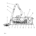
- FIG. 1 schematically shows a simplified vacuum cleaner 1 in one embodiment as a vacuum cleaner.
- the invention is basically suitable for any vacuum cleaner 1, which is equipped with a blower unit with a motor-driven suction fan 2 as a drive unit.
- the vacuum cleaner 1 shown has a housing 3 which is divided into a fan chamber 4 and a dust collecting space 5.
- the suction fan 2 is directed with its suction side to the dust collection chamber 5 and generates there a negative pressure, which is passed through a connected suction hose 6 and a suction pipe 7 to the suction mouth of a floor nozzle 8.
- air laden with dirt 9 - represented by the arrows 10 - is absorbed on the processed substrate (suction air stream) and cleaned by means of a dust separator.
- the cleaned air is discharged through an exhaust filter unit 13 back to the environment.
- the control of a fan motor 14 of the suction fan 2 is carried out in a conventional manner via control electronics of a control unit 15 for controlling, for example power semiconductors of an inverter 16.
- the control unit 15 is an example of a drive unit control or the control unit 15 includes such a drive unit control.
- the fan motor 14 of the suction fan 2 is fed during operation of the vacuum cleaner 1 in a conventional manner with electrical power.
- the suction fan 2 thus generates a negative pressure and finally a volume flow as the basis for the suction air flow.
- an operating and display device 17 is provided for operation and for user information.
- a measure of a volume flow generated during operation in particular analogous values for the actual volume flow q
- various solutions come into consideration: For example, a particular analog differential pressure sensor in the immediate vicinity of the suction fan 2, for example in the range of there usually provided motor protection grille.
- the measured differential pressure between static / dynamic pressure decrease correlates very well with the volume flow q in the measuring range under consideration.
- a Hitz wire a pressure connection to the suction fan 2 or the derivation of the volume flow q from the engine characteristics thinkable and feasible.
- the central suspension of the suction fan or a rubber seal of the suction fan is particularly suitable as a location for the measurement of the volume flow, because there prevail the largest flow velocities.
- a rubber seal of the suction fan is particularly suitable as a location for the measurement of the volume flow, because there prevail the largest flow velocities.
- inject appropriate sensors in the central suspension / rubber seal for example.
- a pressure sensor as a differential pressure sensor against ambient pressure in the region of the inlet opening of the vacuum cleaner 1 into consideration, the pressure in the suction hose 6 or to capture at the entrance of the dust bag 11.
- the negative pressure measured there can still be compensated by the volume flow-dependent pressure drop in the suction hose 6 in order to guarantee a constant suction power at the end of the suction hose 6.
- this would indeed be dispensed with, but it would require additional wiring effort to the floor nozzle 8.
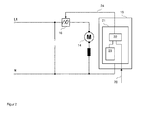
- the in FIG. 2 Drive unit controller 21 shown as a functional unit of the control unit 15, a comparator 22 as a means for comparison the volumetric flow measured value 20 with a predetermined or predeterminable and, for example, stored in a memory 23 volumetric flow upper limit.
- the inverter 16 is actuated via an activatable signal output 24 as a means for reducing the electrical power consumption of the suction fan 2 (drive unit) as an actuator for the drive unit by generating a related control signal.
- a measure of the negative pressure that is, for example, a negative pressure measured value 25
- the in FIG. 2 Drive unit controller 21 shown as a functional unit of the control unit 15 a comparator according to the above-mentioned comparator 22 as a means for comparing the negative pressure measured value 25 with a predetermined or predetermined and for example stored in a memory 23 vacuum lower limit.
- the inverter 16 is actuated via an activatable signal output 24 as means for reducing the electrical power consumption of the suction fan 2 (drive unit) as an actuator for the drive unit by generating a related control signal.
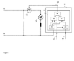
- the implementation of the invention and its embodiments is particularly considered in software or firmware, so that, for example, the comparator 22 as a software or firmware functionality in a control program 30 (FIG. FIG. 3 ) is implemented in the memory 23 of the power plant controller 21.
- the further explanation is continued without abandoning the broader general validity based on the assumption of a software implementation, although in principle a hardware implementation or a combined implementation in software and hardware is conceivable.
- FIG. 3 shows a flowchart for re-explanation of the principles of the approach according to the invention.
- a processing unit (not shown) in the form of or in the manner of a microprocessor, ASICs or the like by means of the drive unit controller 21, first a measure of a volume flow generated by the vacuum cleaner 1 in operation and / or a measure of the volume flow generated by the vacuum cleaner 1 during operation, on the one hand, and a measure of a vacuum generated by the vacuum cleaner 1 during operation, on the other hand, and a calculated variable from the volume flow and negative pressure as a measure of a suction power (first function block 31).
- a second functional block 32 the detected volume flow with a predefined or predefinable volumetric flow upper limit and / or the arithmetic variable with the prespecified or specifiable as a design limit Threshold compared.
- the electrical power consumption of the drive unit is then possibly reduced by appropriate control of the inverter 16 (third function block 33). Thereafter, unless an abort is caused by its execution, the control program is cyclically continued by re-execution of the first function block 31.
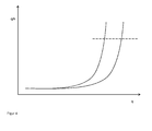
- FIG. 4 shows the course of the calculated size with a first, left curve for a full or at least partially filled dust bag and in a right curve for an empty dust bag.
- the curves are plotted on the abscissa above a respective volumetric flow and on the ordinate over a ratio of volumetric flow and negative pressure. It can be seen that both curves - that is, regardless of the degree of filling of the dust bag - rise sharply for increasing volumetric flow readings.
- the design limit can be drawn as a horizontal line (in FIG. 4 dashed line) and the same numerical value of the design limit can be used for situations with empty, partially filled to full dust bag.
- FIG. 5 shows on the basis of the flowchart in FIG FIG. 3 a particular embodiment of the control program 30, in which it is checked with an intermediate fourth function block 34, whether the detected volume flow exceeds the upper flow limit longer than a predefined or predefinable time limit duration, and the reduction of power consumption by execution of the third function block 33 only at Reaching or exceeding the time limit takes place.
- an arithmetic variable is formed within the first functional block 31, for example a ratio between volumetric flow and negative pressure.
- This variable can be compared, analogously as described above, with a threshold value predetermined or predeterminable as the rated limit, for example within the second functional block 32.
- a reduction of the power consumption of the drive assembly can then take place. This can be done by driving the inverter 16 directly ( FIG. 3, FIG.
- a negative pressure measured value 25 is processed in the form of a variable formed from the volumetric flow measured value 20 and the negative pressure measured value 25 (ratio of the volumetric flow measured value 20 to the negative pressure measured value 25), for example in the form of a quotient of the volumetric flow measured value 20 and the negative pressure measured value 25.
- the calculated size can be formed in basically any form. In the foreground is a sufficient steepness in variations of the volume flow measurement 20 (see FIG. 4 ).
- the respective numerical value of the arithmetic variable can therefore be the result of a mathematical relation, for example as a quotient of the volumetric flow measured value 20 and the negative pressure measured value 25 or as a quotient of the square or higher powers of the volumetric flow measured value 20 and the negative pressure measured value 25, eg q ⁇ n / h ⁇ n , q ⁇ n / h, etc., or an algorithm and the like.
- a corresponding functional unit 26 is provided.
- the arithmetic variable is then compared by a comparator 27 with a predetermined or predetermined threshold value, which is stored, for example in the memory 23 and retrievable there.
- the output signals of the two comparators 22, 27 are logically linked in a suitable manner by a logic unit 28, for example an AND gate, and as a result of this combination, a signal is generated via the activatable signal output 24, depending on the type of connection and input signals for the logic unit 28 generated to drive the inverter 16.
- a logic unit 28 for example an AND gate
- the activatable signal output 24 can thus be activated both as a function of the result of the comparison of the detected duration and time limit value (comparator 22, linking unit 28) and also depending on the result of the comparison of the calculated value with the design limit (functional unit 26, comparator 27, linking unit 28). If - as proposed here - it is provided that both conditions realized by the comparators 22, 27 have to be fulfilled for the reduction of the electrical power consumption of the drive unit, the linking unit 28 is an AND gate or a functionally equivalent unit. If a fulfillment of only one of the conditions is to be sufficient, the linking unit 28 is a corresponding OR gate.
- the branch with the comparator 22 and the combining unit 28 can be dispensed with and the output of the comparator 27 can be applied directly to the activatable signal output 24.
- FIG. 7 shows a further embodiment of the control program 30.
- an effected reduction of the power consumption of the drive unit is detected as the state of the vacuum cleaner 1 by in the cyclic execution of the control program 30 and as long as the conditions expressed by the second and fourth function blocks 32, 34, are always met is branched to the third functional block 33 and thus the control of the inverter 16 is maintained to reduce the power consumption.
- Other ways of detecting such a condition such as by setting a corresponding flag in the control program 30 and interrogating it elsewhere, are also conceivable.
- a possible decrease in the volume flow and / or an increase in the negative pressure is checked by a fifth function block 35 and, depending on the result of this check, if necessary a sixth function block 36 is called up. with the reduction of the electrical power consumption of the drive unit is withdrawn.
- the drive unit in connection with the withdrawal of the reduction of the electrical power consumption of the drive unit, the drive unit is at least briefly acted upon by a respective maximum allowable motor voltage. Furthermore, it can be provided that a duration of the brief application of the drive unit with the respective maximum permissible motor voltage depends on a preselected power position for the drive unit. For example, in memory 23 (FIG. FIG. 2 . FIG. 6 ), a so-called look-up table (LUT) which for each possible power position or a plurality of power value value ranges each includes a time value. This is read out of the memory 23 / the LUT upon activation of the drive unit and used for monitoring the duration of the drive of the drive unit.
- LUT look-up table
- FIG. 3 shows a flowchart for an embodiment of the method or a subsequent drive unit control based on the illustration in FIG. 7 .
- a seventh function block 37 is checked whether the state of reduction of electrical power consumption already longer than a by a predetermined or predetermined threshold value, which is stored for example in the memory 23, expressed time period exists. If this is the case, the drive unit is deactivated and branched to an eighth function block 38, which causes the deactivation of the drive unit.
- a ninth functional block 39 can connect to the eighth functional block 38, with which, for example, a user action, for example a movement of the floor nozzle or the actuation of a push-button of the operating and display device 17, is monitored.
- control program 30th is started with newly initialized starting values with regard to the recorded measured values 20, 25 or the monitored times and the drive unit initially runs as usual until the floor nozzle or the suction pipe is removed from the ground and the stop mechanism or start-stop system described here is started. Automatic to avoid unnecessary energy consumption in the activation state of the drive unit engages.
- a possible by the user or the manufacturer of the vacuum cleaner or customer service calibration of the automatic stop or start-stop automatic is conceivable.
- a calibrating mode intended for calibration would be activated on the vacuum cleaner, for example by actuating a corresponding switching element or by actuating an already existing switching element for more than a predetermined duration.
- the power plant controller indicates the beginning of the calibration by means of a signal emitted by the vacuum cleaner, for example a flashing display device. Then the floor nozzle is lifted and kept in the off position for, for example, at least two seconds. After a predetermined period of time, for example two seconds, the drive unit control detects the volumetric flow measured value 20 and the negative pressure measured value 25. The two measured values recorded are temporarily stored.
- the vacuum Upon completion of the acquisition of these readings, the vacuum will signal the beginning of a second part of the calibration. On such a signal, the floor nozzle is placed and kept for example at least two seconds in the mounted state. After a predetermined period of time, for example two seconds, the drive unit control again detects the volumetric flow measured value 20 and the negative pressure measured value 25. These two measured values are also temporarily stored. From the two cached measured values for the volumetric flow, a new value for the volumetric flow upper limit can be directly derived, for example as the mean value between the two measured values. The new upper flow limit will be in memory, for example a non-volatile memory, the drive unit control stored.
- values for a rated limit can be formed in each case with the values stored temporarily in pairs for the volume flow and negative pressure, and the new rated limit then also results, for example, as the mean value between the two previously formed values.
- the new rated limit is also stored in the memory, for example a non-volatile memory, of the drive unit control.
- the new volume flow upper limit and / or the new rated limit are available as device-specific calibrated or updated limit values.
- Such a calibration helps to identify aging influences and resulting changes in the vacuum and volume flow that can be reached during operation and to adjust the switching conditions for activating the stop or start-stop system. Furthermore, with such a calibration, it is also possible to adapt the switching conditions to different bottom nozzles.
- vacuum cleaner 1 with a drive unit and a drive unit controller 21 and a method for operating such a vacuum cleaner 1, said the drive unit in the operation of the vacuum cleaner 1 due to supplied electrical power generates a volume flow and a negative pressure
- vacuum cleaner 1 and drive unit control 21 are characterized in that the vacuum cleaner 1 comprises means for detecting a measure of the volume flow generated during operation and a measure of the negative pressure generated during operation and the drive unit controller 21 means 22nd for comparing the detected volumetric flow and a predetermined or predefinable volumetric flow upper limit and / or means 27 for comparing a calculated variable formed from the detected volumetric flow and the detected negative pressure with a designation limit or predeterminable threshold, and means 16, 24 for reducing the electrical power consumption depending on the result of the comparison or both comparisons includes or controls.
- an automatic stop function is realized, in further embodiments even an automatic start-stop function.
- the functionality that implements the automatic switch-off and possibly the restarting of the drive unit can be embodied as permanently active functionality or as user-activatable functionality. In the case of a basically permanently active functionality, it can be provided that the functionality can be deactivated by the user.
Abstract
Description
Die Erfindung betrifft einen Staubsauger und ein Verfahren zum Betrieb eines Staubsaugers. Staubsauger sind an sich bekannt und werden mit elektrischem Strom entweder aus einem Leitungsnetz oder einer mitgeführten Spannungsquelle, nämlich einem Akkumulator oder dergleichen, betrieben.The invention relates to a vacuum cleaner and a method for operating a vacuum cleaner. Vacuum cleaners are known per se and are operated with electric power either from a mains network or from an entrained voltage source, namely an accumulator or the like.
Staubsauger entnehmen eine vergleichsweise hohe elektrische Leistung aus der jeweiligen Spannungsquelle und wandeln sie in eine Luft- oder Saugleistung an einer Bodendüse oder einem Saugrohr um. Die Saugleistung ergibt sich dabei als Produkt von Unterdruck einerseits und Volumenstrom oder Durchfluss andererseits. Während des Saugvorgangs ergibt sich mit aufgesetzter Bodendüse ein bevorzugter Arbeitsbereich mit guter Effizienz, also einem guten Verhältnis von aufgenommener elektrischer Leistung und abgegebener Saugleistung, etwa bei der Hälfte des maximal möglichen Volumenstroms. Oftmals wird allerdings während des Saugens die Bodendüse oder das Saugrohrende vom Boden abgenommen und beiseite gelegt, um z.B. Möbelstücke zu verrücken, den Staubsauger nachzuführen oder auch um in ein anderes Zimmer zu gehen, ein Telefongespräch anzunehmen oder einfach nur, um das Saugen kurz zu unterbrechen. Während dieser Zeit wird üblicherweise der Staubsauger vom Benutzer nicht abgeschaltet, sondern läuft mit maximalem Volumenstrom, aber ohne Saugleistung, weiter. Aus energetischer Sicht ist besonders ungünstig, dass in dieser Situation die maximale Leistung aus der Spannungsquelle entnommen wird, aber keine Saugleistung an der Bodendüse zur Verfügung steht und auch nicht benötigt wird. Darüber hinaus kommt hinzu, dass die übliche Geräuschentwicklung eines Staubsaugers während der gesamten Phase der Nichtbenutzung andauert.Vacuum cleaners remove a comparatively high electrical power from the respective voltage source and convert it into an air or suction power at a floor nozzle or a suction pipe. The suction power results as a product of negative pressure on the one hand and volume flow or flow on the other. During the suction process results with attached floor nozzle a preferred work area with good efficiency, ie a good ratio of absorbed electrical power and emitted suction, about half of the maximum possible flow rate. Often, however, during suction, the floor nozzle or the suction tube end is removed from the floor and set aside to remove e.g. Moving furniture, moving the vacuum cleaner or even going to another room, picking up a phone call, or just to stop sucking. During this time usually the vacuum cleaner is not switched off by the user, but continues with maximum flow, but without suction, on. From an energetic point of view is particularly unfavorable that in this situation, the maximum power is taken from the power source, but no suction power at the floor nozzle is available and is not needed. In addition, there is the fact that the usual noise of a vacuum cleaner continues throughout the period of non-use.
Zur Vermeidung eines unnötig hohen Energieverbrauchs durch das Sauggebläse und im Weiteren zur Vermeidung der mit dem Betrieb des Sauggebläses einhergehenden Geräuschentwicklung während der Dauer der Nichtbenutzung oder zur Erkennung einer Nichtbenutzungssituation sind unterschiedliche Vorschläge bekannt geworden:
- Aus der
WO 02/091899 A
- From the
WO 02/091899 A
Eine Betrachtung einer Schwankung von Druckmesswerten liegt auch dem Ansatz der
Die
Die
Aus der
Aus der
Eine Aufgabe der Erfindung besteht darin, einen Staubsauger und ein Verfahren zum Betrieb eines Staubsaugers anzugeben, bei dem eine Nichtbenutzungssituation zuverlässig erkannt wird und so ein unnötig hoher Energieverbrauch durch das Antriebsaggregat des Sauggebläses und im Weiteren die mit dem Betrieb des Sauggebläses einhergehende Geräuschentwicklung während der Dauer der Nichtbenutzung vermieden wird.An object of the invention is to provide a vacuum cleaner and a method for operating a vacuum cleaner, in which a non-use situation is reliably detected, and so unnecessarily high energy consumption by the drive unit of the suction fan and further associated with the operation of the suction fan noise during the period the non-use is avoided.
Diese Aufgabe wird erfindungsgemäß mit den Merkmalen des Anspruchs 1 gelöst.This object is achieved with the features of
Dazu ist bei einem Staubsauger mit einem Antriebsaggregat und einer Antriebsaggregatsteuerung, wobei das Antriebsaggregat im Betrieb des Staubsaugers aufgrund zugeführter elektrischer Leistung einen Volumenstrom und einen Unterdruck erzeugt, zunächst vorgesehen, dass der Staubsauger Mittel zur Erfassung eines Maßes für den im Betrieb erzeugten Volumenstrom sowie Mittel zur Erfassung eines Maßes für den im Betrieb erzeugten Unterdruck umfasst. Ohne Verzicht auf eine weitergehende Allgemeingültigkeit wird im Folgenden im Interesse einer besseren Lesbarkeit mitunter die Formulierung "zur Erfassung eines Maßes" bei der Erfassung eines Maßes für eine jeweilige Größe weggelassen. Für den Fachmann ist selbstverständlich, dass sich gleichwertige Lösungen ergeben, wenn eine jeweilige Größe nicht unmittelbar erfassbar, aber ein Maß für die jeweilige Größe erfassbar ist und stattdessen mit diesem Maß für die jeweilige Größe gearbeitet wird. Ein Maß für einen im Betrieb erzeugten Volumenstrom oder ein Maß für einen im Betrieb erzeugten Unterdruck ist zum Beispiel eine jeweils proportionale oder umgekehrt proportionale elektrische Stromstärke oder elektrische Spannung. Ganz allgemein ist eine Erfassung eines Maßes für eine bestimmte Größe die Erfassung eines jeweiligen Messwertes und die Generierung und/oder Weiterleitung eines diesbezüglichen Signals.For this purpose, in a vacuum cleaner with a drive unit and a drive unit control, wherein the drive unit generates a volume flow and a negative pressure in operation of the vacuum cleaner due to supplied electrical power, provided first that the vacuum cleaner means for detecting a measure of the volume flow generated during operation and means for Detecting a measure of the negative pressure generated during operation includes. Without waiving any further generality, the phrase "to capture a measure" is sometimes omitted in the following for the sake of better readability in determining a measure of a particular size. It will be understood by those skilled in the art that equivalent solutions will result if a particular size is not immediately detectable, but a measure of the particular size is detectable and, instead, that measure is used for the particular size. A measure of a volume flow generated during operation or a measure of a negative pressure generated during operation is, for example, a respective proportional or inversely proportional electrical current or voltage. In general, detection of a measure for a particular quantity is the acquisition of a respective measured value and the generation and / or transmission of a relevant signal.
In diesem Sinne wird diese Formulierung im Weiteren mitunter auch für andere betrachtete Größen weggelassen und der in Anspruch 1 definierte Staubsauger zeichnet sich im Weiteren dadurch aus, dass dessen Antriebsaggregatsteuerung Mittel zum Bilden einer Rechengröße aus dem erfassten Volumenstrom und dem erfassten Unterdruck, optionale Mittel zum Vergleich des erfassten Volumenstroms mit einer vorgegebenen oder vorgebbaren Volumenstromobergrenze, aber jedenfalls Mittel zum Vergleich der Rechengröße mit einem als Bemessungsgrenze vorgegebenen oder vorgebbaren Schwellwert umfasst. Durch den Vergleich des Volumenstroms mit der Volumenstromobergrenze kann eine Situation erkannt werden, bei der die Bodendüse vom Boden abgenommen ist, weil in dieser Situation der Volumenstrom deutlich ansteigt. Die vom Boden abgenommene Bodendüse ist dabei ein Erkennungsmerkmal für eine Nichtbenutzungssituation, weil zum Beispiel auch bei einem abgelegten Saugrohr die Bodendüse ganz oder teilweise vom Boden abgehoben ist. Durch den Vergleich der Rechengröße mit der Bemessungsgrenze kann ein abgehobener Zustand der Bodendüse sicher erkannt werden. Bei einer parallelen Betrachtung von Volumenstrom und Rechengröße wird zudem eine Fehlauswertung vermieden, die zum Beispiel möglich ist, wenn sich der erhöhte Volumenstrom durch einen neuen, leeren Saugbeutel ergibt. Als Basis für die Rechengröße kommt zum Beispiel ein Verhältnis des Volumenstroms zum Unterdruck, insbesondere ein Quotient aus dem Volumenstrom und dem Unterdruck, sowie ein diesbezügliches Signal in Betracht oder ein Quotient aus dem Quadrat des Volumenstroms und dem Unterdruck (jedes Verhältnis des Volumenstroms zum Unterdruck, insbesondere jeder aus Volumenstrom und Unterdruck gebildete Quotient, ist gewissermaßen auch ein Maß für die Saugleistung, weil sich die Saugleistung als Produkt aus dem Volumenstrom und dem Unterdruck ergibt), so dass die Rechengröße grundsätzlich auch allein aussagekräftig im Hinblick auf einen erhöhten Volumenstrom und ein dafür ursächliches Abheben der Bodendüse vom Boden ist. Die zum Beispiel in Form eines Quotienten oder sonstigen Verhältnisses aus Volumenstrom und Unterdruck gebildete Rechengröße steigt nämlich stark an, wenn der für den jeweiligen Füllgrad des Staubbeutels/Staubsammelbehälters des Staubsaugers maximale Volumenstrom erreicht ist. Zur Bildung der Rechengröße kommt grundsätzlich jeder qualifizierte Berechnungsalgorithmus in Betracht, der als Eingangsgrößen ein Maß für den Volumenstrom q und ein Maß für den Unterdruck h verrechnet. Mit einem Algorithmus auf der Basis q*q/h zur Grenzwertbildung wurden besonders gute Erfahrungen gemacht.In this sense, this formulation is sometimes omitted below for other sizes considered and defined in
Die Antriebsaggregatsteuerung umfasst damit schließlich auch Mittel zum Reduzieren der elektrischen Leistungsaufnahme des Antriebsaggregats in Abhängigkeit sowohl vom Ergebnis des Vergleichs des Volumenstroms mit der Volumenstromobergrenze wie auch vom Ergebnis des Vergleichs der Rechengröße mit der Bemessungsgrenze. Alternativ kann vorgesehen sein, dass die Antriebsaggregatsteuerung die Mittel zum Reduzieren der elektrischen Leistungsaufnahme des Antriebsaggregats nicht selbst umfasst, aber ansteuert.Finally, the drive unit control also comprises means for reducing the electrical power consumption of the drive unit as a function of both the result of the comparison of the volume flow with the volume flow upper limit and the result of the comparison of the calculated value with the design limit. Alternatively, it can be provided that the drive unit control does not itself comprise the means for reducing the electrical power consumption of the drive unit, but controls it.
Bei der
Die
Der Vorteil der Erfindung besteht darin, dass mit der Erfassung eines Maßes für den Volumenstrom und der Erfassung eines Maßes für den Unterdruck eine direkte Ermittlung der zur Bestimmung der Saugleistung relevanten Parameter erfolgt, so dass eine indirekte Saugleistungsmessung oder zumindest eine indirekte Ermittlung eines Maßes für die Saugleistung erfolgt, die auf eine direkte Messung der dafür relevanten Parameter zurückgeführt ist. Anhand des in Form der Rechengröße jeweils ermittelten Maßes für die Saugleistung kann die Benutzungssituation einfach und sicher erkannt werden, speziell eine Nichtbenutzungssituation kann leicht erkannt werden, weil in einer Nichtbenutzungssituation die Saugleistung sofort drastisch zurückgeht und schließlich verschwindet. Der Vorteil der Erfindung besteht im Weiteren darin, dass mit der so gewährleisteten verbesserten Erkennung der Nichtbenutzungssituation eine automatische Stopp-Funktion für den Staubsauger realisiert wird - durch weitere Ausgestaltungen sogar eine automatische Start-Stopp-Funktion -welche die Leistungsaufnahme dann reduziert, wenn die elektrische Leistung tatsächlich nicht benötigt wird. Entsprechend wird der hier vorgeschlagene Ansatz im Folgenden auch kurz als Start-Stopp-Funktion bezeichnet. Des Weiteren wird im Folgenden die Reduktion der Leistungsaufnahme des Antriebsaggregats ohne Verzicht auf die weitergehende Allgemeingültigkeit auch kurz als "Abschalten" des Antriebsaggregats bezeichnet, auch wenn dieses Abschalten evtl. nicht eine vollständige, sondern nur eine teilweise Reduktion der Leistungsaufnahme bedeutet. Ein solches Abschalten des Staubsaugers bedeutet immer auch eine Beendigung oder zumindest eine Verringerung der üblichen Geräuschentwicklung des Staubsaugers.The advantage of the invention is that with the detection of a measure of the volume flow and the detection of a measure of the negative pressure, a direct determination of the relevant parameters for determining the suction power, so that an indirect suction power measurement or at least an indirect determination of a measure of the Suction power, which is attributed to a direct measurement of the relevant parameters. On the basis of the calculation variable in each case determined measure of the suction performance, the use situation can be easily and reliably detected, especially a non-use situation can be easily detected, because in a non-use situation, the suction decreases immediately drastically and finally disappears. The advantage of the invention is further that with the thus ensured improved detection of the non-use situation, an automatic stop function for the vacuum cleaner is realized - by further embodiments, even an automatic start-stop function -which reduces the power consumption when the electric Performance is actually not needed. Accordingly, the approach proposed here is also referred to below as the start-stop function. Furthermore, the reduction in power consumption of the drive unit without renouncing the broader general validity is also referred to below as "switching off" the drive unit, even if this shutdown may not be a complete, but only a partial reduction in power consumption means. Such a shutdown of the vacuum cleaner always means a termination or at least a reduction of the usual noise of the vacuum cleaner.
Vorteilhafte Ausgestaltungen der Erfindung sind Gegenstand der Unteransprüche. Dabei verwendete Rückbeziehungen weisen auf die weitere Ausbildung des Gegenstandes des Hauptanspruches durch die Merkmale des jeweiligen Unteranspruches hin. Sie können auch selbständige Erfindungen enthalten, die eine von den Gegenständen der vorhergehenden Ansprüche unabhängige Gestaltung aufweisen und sind nicht als ein Verzicht auf die Erzielung eines selbständigen, gegenständlichen Schutzes für deren Merkmale zu verstehen. Des Weiteren ist im Hinblick auf eine Auslegung der Ansprüche bei einer näheren Konkretisierung eines Merkmals in einem nachgeordneten Anspruch davon auszugehen, dass eine derartige Beschränkung in den jeweils vorangehenden Ansprüchen nicht vorhanden ist.Advantageous embodiments of the invention are the subject of the dependent claims. Here used backlinks indicate the further development of the subject matter of the main claim by the features of the respective subclaim. They may also contain independent inventions having a design independent of the objects of the preceding claims and are not to be understood as a waiver of obtaining independent, objective protection of their characteristics. Furthermore, with a view to an interpretation of the claims in a closer specification of a feature in a subordinate claim, it is to be assumed that such a restriction does not exist in the respective preceding claims.
Bei einer Ausführungsform der Staubsaugers ist vorgesehen, dass die Antriebsaggregatsteuerung Mittel zum Erfassen einer Dauer einer Überschreitung der Volumenstromobergrenze durch den erfassten Volumenstrom sowie Mittel zum Vergleich der Dauer der Überschreitung mit einem vorgegebenen oder vorgebbaren Zeitgrenzwert und als Mittel zum Reduzieren der elektrischen Leistungsaufnahme einen in Abhängigkeit vom Ergebnis des Vergleichs von erfasster Dauer und Zeitgrenzwert aktivierbaren Signalausgang umfasst. Auf diese Weise wird erreicht, dass die Stopp-Funktion erst dann tatsächlich aktiviert wird, wenn die Bedingung für deren Aktivierung für eine gewisse Zeitdauer erfüllt ist, so dass z.B. nicht jedes kurzzeitige Anheben der Bodendüse und die damit einhergehende kurzzeitige Erhöhung des Volumenstroms zu einem unerwünschten Abschalten des Antriebsaggregats führt. Sinnvolle Werte für den Zeitgrenzwert liegen nach der Erkenntnis des Erfinders in Größenordnungen von 50 ms bis 200 ms.In one embodiment of the vacuum cleaner it is provided that the drive unit control means for detecting a duration of exceeding the upper limit of the volume flow through the detected volume flow and means for comparing the duration of the excess with a predetermined or predetermined time limit and as a means for reducing the electrical power consumption depending on Result of comparison of detected duration and time limit activatable signal output includes. In this way it is achieved that the stop function is actually activated only when the condition for its activation is fulfilled for a certain period of time, so that e.g. not every brief lifting of the floor nozzle and the concomitant short-term increase in the volume flow leads to an undesired shutdown of the drive unit. Sensible values for the time limit are according to the knowledge of the inventor in the order of magnitude of 50 ms to 200 ms.
Bei dieser Ausführungsform wird also der erfasste Volumenstrom mit der Volumenstromobergrenze verglichen und bei Überschreitung der Volumenstromobergrenze um eine durch den Zeitgrenzwert vorgegebene Dauer ist eine Aktivierung des Signalausgangs der Antriebsaggregatsteuerung möglich. Tatsächlich erfolgt die Aktivierung des Signalausgangs aber nur dann, wenn zusätzlich noch der anhand der Messwerte für Unterdruck und Volumenstrom gebildete Wert der Rechengröße die Bemessungsgrenze überschreitet. Alternativ kommt auch in Betracht, nur die Rechengröße, also zum Beispiel den Quotienten aus Volumenstrom und Unterdruck, und die Bemessungsgrenze für die Aktivierung der Stopp-Funktion, ggf. mit Berücksichtigung eines Zeitgrenzwerts, vorzusehen. Unabhängig von der konkreten Ausführungsform erlaubt die Bemessungsgrenze eine Berücksichtigung der Widerstände des Staubbeutels sowie der Motor- und Abluftfilter einerseits sowie der momentanen Leistungseinstellung für das Antriebsaggregat andererseits.In this embodiment, therefore, the detected volumetric flow is compared with the volumetric flow upper limit, and when the volumetric flow upper limit is exceeded by a duration predetermined by the time limit, activation of the signal output of the drive aggregate control is possible. Actually, however, the signal output is only activated if, in addition, the value of the calculated variable formed on the basis of the measured values for negative pressure and volumetric flow exceeds the rated limit. Alternatively, it is also possible to provide only the arithmetic variable, that is, for example, the quotient of volumetric flow and negative pressure, and the design limit for the activation of the stop function, possibly taking into account a time limit value. Regardless of the specific embodiment, the design limit allows consideration of the resistances of the dust bag and the engine and exhaust filters on the one hand and the current power setting for the drive unit on the other.
In einer weiteren Ausführungsform weist der Staubsauger eine Verknüpfungsfunktionalität, zum Beispiel ein UND-Gatter oder dergleichen, als Mittel zum Verknüpfen des Ergebnisses des Vergleichs von erfasster Dauer und Zeitgrenzwert einerseits und des Ergebnisses des Vergleichs der Rechengröße und der Bemessungsgrenze andererseits auf, wobei ein Ausgang dieser Verknüpfungsfunktionalität den aktivierbaren Signalausgang darstellt. Der aktivierbare Signalausgang kann dann auf ein Stellglied zur Reduktion der Leistungsaufnahme des Antriebsaggregats geschaltet werden und damit im oben erläuterten Sinne das "Abschalten" des Antriebsaggregats bewirken.In a further embodiment, the vacuum cleaner has a linking functionality, for example an AND gate or the like, as a means for combining the result of the comparison of the detected duration and time limit on the one hand and the result of the comparison of the calculated value and the design limit on the other hand, an output of this Linking functionality represents the activatable signal output. The activatable signal output can then be switched to an actuator to reduce the power consumption of the drive unit and thus cause the "shutdown" of the drive unit in the sense explained above.
Indem eine bewirkte Reduktion der Leistungsaufnahme des Antriebsaggregats als Zustand des Staubsaugers erfasst wird und während eines solchen Zustands bei einem Absinken des Volumenstroms und/oder einem Ansteigen des Unterdrucks die Reduktion der elektrischen Leistungsaufnahme des Antriebsaggregats zurückgenommen wird, lässt sich das "Abschalten" des Antriebsaggregats aufheben, wenn sich die Betriebssituation ändert, wenn also z.B. die abgehobene Bodendüse wieder aufgesetzt wird und der Benutzer den Saugvorgang fortsetzt. Für den Benutzer ergibt sich damit eine vollautomatische Start-Stopp-Funktion, nämlich einerseits ein automatisches "Abschalten" (Stopp-Funktion) und andererseits ein automatisches Wiederanlaufen des Antriebsaggregats (Start-Funktion). Die Erfassung eines Absinkens des Volumenstroms oder eines Ansteigens des Unterdrucks oder aber eines Absinkens des Volumenstroms und eines gleichzeitigen Ansteigens des Unterdrucks sind ausdrücklich unabhängige und zumindest im Wesentlichen gleichwertige Kriterien für das automatische Wiederanlaufen des Antriebsaggregats. Wenn nur oder auch der Unterdruck betrachtet wird, kommt speziell in Betracht, sensierte Druckänderungen zu addieren und aus der Überschreitung eines Schwellwertes durch die so gebildete Summe ein Signal zur Reaktivierung des Antriebsaggregats abzuleiten.By an effected reduction of the power consumption of the drive unit is detected as the state of the vacuum cleaner and during such a state with a decrease in the volume flow and / or an increase in the negative pressure, the reduction of the electric Power consumption of the drive unit is withdrawn, can be the "shutdown" of the drive unit cancel when the operating situation changes, so if, for example, the lifted floor nozzle is replaced and the user continues the suction process. For the user, this results in a fully automatic start-stop function, namely on the one hand an automatic "shutdown" (stop function) and on the other hand, an automatic restart of the drive unit (start function). The detection of a decrease in the volume flow or an increase in the negative pressure or a decrease in the volume flow and a simultaneous increase in the negative pressure are expressly independent and at least substantially equivalent criteria for the automatic restart of the drive unit. If only or even the negative pressure is considered, is particularly considered to add sensed pressure changes and deriving from the exceeding of a threshold by the sum thus formed a signal to reactivate the drive unit.
Indem beim Wiederanlauf, also im Zusammenhang mit der Rücknahme der Reduktion der elektrischen Leistungsaufnahme des Antriebsaggregats, das Antriebsaggregat zumindest kurzzeitig mit einer jeweils maximal zulässigen Motorspannung beaufschlagt wird, lässt sich die der Leistungseinstellung entsprechende Betriebssituation des Staubsaugers vor der automatischen Deaktivierung schneller wieder erreichen.By at rest, ie in connection with the withdrawal of the reduction of the electrical power consumption of the drive unit, the drive unit is at least briefly applied with a respective maximum allowable motor voltage, the performance setting corresponding operating situation of the vacuum cleaner before automatic deactivation can be achieved faster again.
Wenn sich eine Dauer der kurzzeitigen Beaufschlagung des Antriebsaggregats mit der jeweils maximal zulässigen Motorspannung nach einer für das Antriebsaggregat vorgewählten Leistungsstellung richtet, ergibt sich ein dynamischer Wiederanlauf des Antriebsaggregats in Abhängigkeit von der zu erreichenden Betriebssituation vor der automatischen Deaktivierung.If a duration of the short-term loading of the drive unit with the respective maximum permissible motor voltage depends on a pre-selected for the drive unit power position, there is a dynamic restart of the drive unit depending on the operating situation to be achieved before the automatic deactivation.
Wenn im Zustand einer bewirkten Reduktion der Leistungsaufnahme des Antriebsaggregats eine Dauer dieses Zustands erfasst wird und bei einer einen vorgegebenen oder vorgebbaren Schwellwert überschreitenden Dauer das Antriebsaggregat deaktiviert wird, ist die automatische Stopp-Funktion oder die automatische Start-Stopp-Funktion sinnvoll dahingehend ergänzt, dass zunächst und quasi als Stopp-Funktion ersten Grades die Leistungsaufnahme reduziert, aber noch nicht auf Null reduziert wird, und dass die Reduktion der Leistungsaufnahme auf Null, also das tatsächliche Abschalten des Antriebsaggregats, erst erfolgt, wenn innerhalb einer bestimmten Zeit keine Aktivierung des Antriebsaggregats durch Weiterbenutzung des Staubsaugers erfolgt (Stopp-Funktion zweiten Grades). Bei einem abgeschalteten Antriebsaggregat kann vorgesehen sein, dass dieses nur über eine Benutzeraktion, zum Beispiel das Betätigen eines Tasters oder dergleichen oder eine über einen Bewegungssensor erfassbare Bewegung der Bodendüse, wieder aktivierbar ist. Dies ermöglicht das vollständige Abschalten nicht nur des Antriebsaggregats, sondern auch der Ansteuerelektronik und damit eine Reduktion des Energieverbrauchs des Staubsaugers auf Null oder nahezu Null. Sinnvolle Werte für den Schwellwert liegen nach der Erkenntnis des Erfinders in Größenordnungen von etwa dreißig Sekunden.If a duration of this state is detected in the state of a reduced reduction of the power consumption of the drive unit and the drive unit is deactivated at a duration exceeding a predetermined or specifiable threshold value, the automatic stop function or the automatic start-stop function is meaningfully supplemented in that initially and quasi as a stop function of the first degree, the power consumption is reduced, but not yet reduced to zero, and that the reduction of power consumption to zero, so the actual shutdown of the drive unit, only occurs if within a certain time no activation of the drive unit through Further use of the vacuum cleaner takes place (stop function of the second degree). When the drive unit is switched off, it can be provided that this can only be activated again via a user action, for example the actuation of a pushbutton or the like, or a movement of the floor nozzle that can be detected via a movement sensor. This allows the complete shutdown not only of the drive unit, but also the Control electronics and thus a reduction of the energy consumption of the vacuum cleaner to zero or almost zero. Sensible values for the threshold are, according to the inventor's knowledge, of the order of magnitude of about thirty seconds.
Die oben genannte Aufgabe wird auch mit einem Staubsauger gelöst, der nach dem Verfahren wie hier und im Folgenden beschrieben arbeitet und dazu Mittel zur Durchführung des Verfahrens umfasst. Die Erfindung ist dabei bevorzugt zumindest teilweise in Software oder in Soft- und Firm-/Hardware implementiert. Die Erfindung ist insoweit einerseits auch ein Computerprogramm mit durch einen Computer ausführbaren Programmcodeanweisungen und andererseits ein Speichermedium mit einem derartigen Computerprogramm sowie schließlich auch eine Steuerungseinheit in Form einer Antriebsaggregatsteuerung oder mit einer solchen Antriebsaggregatsteuerung oder ein Staubsauger mit einer solchen Steuerungseinheit, in deren Speicher als Mittel zur Durchführung des Verfahrens und seiner Ausgestaltungen ein solches Computerprogramm geladen oder ladbar ist.The above object is also achieved with a vacuum cleaner which operates according to the method as described here and below and comprises means for carrying out the method. The invention is preferably implemented at least partially in software or in software and firmware / hardware. The invention is on the one hand also a computer program with executable by a computer program code instructions and on the other hand, a storage medium with such a computer program and finally a control unit in the form of a drive unit control or with such a drive unit control or a vacuum cleaner with such a control unit, in the memory as a means for Implementation of the method and its embodiments such a computer program is loaded or loadable.
Der Vorteil der Erfindung und ihrer Ausgestaltungen ergibt sich damit insbesondere wie folgt: Während der Staubsauger in einer Situation betrieben wird, bei der z.B. die Bodendüse vom Teppich oder Bodenbelag abgehoben ist und keine Reinigungswirkung auftritt oder andere, kurze Saugpausen eingelegt werden, kann die aufgenommene elektrische Leistung kurzfristig abgesenkt und dynamisch wieder zugeschaltet werden, ohne dass der Benutzer eine Saugleistungseinschränkung hinnehmen oder zusätzliche Aktivitäten durchführen muss. Speziell im Betrieb mit einer vom Teppich abgenommen Bodendüse (offene Blende) wird dem elektrischen Netz die größte Aufnahmeleistung entnommen (P1 = max), obwohl dann keine Saugleistung umgesetzt werden kann (eine Unterdruckerzeugung durch das Antriebsaggregat ist dann kaum noch möglich; der Unterdruck h geht gegen Null und damit geht entsprechend auch die Saugleistung P2 gegen Null). Diese Zustände wurden bisher hingenommen. Im Zuge höherer Energiekosten und eines ökologischen Umdenkens ist eine intelligente Regelung nützlich, mit der die aufgenommene elektrische Leistung je nach Benutzungssituation drastisch reduziert und automatisch wieder angehoben werden kann, ohne den Benutzer einzuschränken oder das Saugergebnis zu beeinträchtigen. Zudem kann mit dem hier vorgeschlagenen Ansatz nicht nur der elektrische Stromverbrauch in den Zeiträumen minimiert werden, in denen nicht im vordefinierten Arbeitsbereich gesaugt wird, sondern auch eine mit dem Betrieb eines Staubsaugers normalerweise einhergehende Geräuschentwicklung minimiert oder zumindest reduziert werden, so dass sich auch ein günstiger akustischer Effekt ergibt. Die Geräusche entstehen zum einen durch die fehlende Geräuschdämmung der Bodendüse auf dem Boden und - viel mehr noch - durch den maximalen Durchfluss und die daraus resultierende maximale Luftgeschwindigkeit. Für die Leistungsreduzierung (automatische Stopp-Funktion) hat sich ein Zeitraum von 50 ms bis 200 ms und für den Hochlauf (automatische Start-Funktion) ein Zeitraum zwischen 20 ms und 100 ms als vorteilhaft bezüglich der Dynamik erwiesen.The advantage of the invention and its embodiments is thus in particular as follows: While the vacuum cleaner is operated in a situation in which, for example, the floor nozzle is lifted off the carpet or floor covering and no cleaning effect occurs or other, short suction breaks are inserted, the recorded electrical Power can be lowered in the short term and dynamically reconnected without the user having to accept a suction power restriction or carry out additional activities. Especially in operation with a floor nozzle removed from the carpet (open panel), the maximum power is taken from the electrical network (P1 = max), although then no suction power can be applied (negative pressure generation by the drive unit is then hardly possible; towards zero and thus also the suction power P2 approaches zero). These conditions have been accepted so far. In the context of higher energy costs and ecological rethinking, an intelligent control is useful, with which the electrical power consumption can be drastically reduced and automatically raised again depending on the usage situation without restricting the user or impairing the suction result. In addition, with the approach proposed here not only the electrical power consumption can be minimized in the periods in which is not sucked in the predefined working area, but also minimizes or at least reduced with the operation of a vacuum noise associated, so that also a cheaper acoustic effect results. The noises are due to the lack of noise insulation of the floor nozzle on the floor and - much more - by the maximum flow and the resulting maximum air velocity. For the power reduction (automatic stop function) has a period of 50 ms to 200 ms and for startup (automatic start function), a period between 20 ms and 100 ms proved to be advantageous in terms of dynamics.
Nachfolgend wird ein Ausführungsbeispiel der Erfindung anhand der Zeichnung näher erläutert. Einander entsprechende Gegenstände oder Elemente sind in allen Figuren mit den gleichen Bezugszeichen versehen. Das oder jedes Ausführungsbeispiel ist nicht als Einschränkung der Erfindung zu verstehen. Vielmehr sind im Rahmen der vorliegenden Offenbarung zahlreiche Abänderungen und Modifikationen möglich, die zum Beispiel durch Kombination oder Abwandlung von einzelnen in Verbindung mit den in der allgemeinen Beschreibung, der oder jeder Ausführungsform sowie den Ansprüchen beschriebenen und in den Zeichnungen enthaltenen Merkmalen bzw. Elementen oder Verfahrensschritten für den Fachmann im Hinblick auf die Lösung der Aufgabe entnehmbar sind und durch kombinierbare Merkmale zu einem neuen Gegenstand oder zu neuen Verfahrensschritten oder Verfahrensschrittfolgen führen.An embodiment of the invention will be explained in more detail with reference to the drawing. Corresponding objects or elements are provided in all figures with the same reference numerals. The or each embodiment is not to be understood as limiting the invention. Rather, within the scope of the present disclosure, numerous modifications and variations are possible, for example, by combination or modification of the individual elements or method steps described in the general description, or each embodiment and the claims, and included in the drawings for the expert with regard to solving the problem can be removed and lead by combinable features to a new object or to new process steps or process steps.
Es zeigen
Figur 1- einen Staubsauger an sich bekannter Art in einer Ausführungsform als Bodenstaubsauger,
Figur 2- eine Antriebsaggregatsteuerung als Mittel zur Implementation des hier beschriebenen Ansatzes,
Figur 3- und
Figur 4- schematisch vereinfachte Flussdiagramme eines durch die Antriebsaggregatsteuerung ausführbaren Steuerungsprogramms als Mittel zur Implementation des hier beschriebenen Ansatzes,
Figur 5- die
Antriebsaggregatsteuerung gemäß Figur 2 mit weiteren, optionalen Details, Figur 6- und
Figur 7- besondere Ausführungsformen des Steuerungsprogramms in Form von Flussdiagrammen auf Basis der in
Figur 3Figur 4 gezeigten Situation.
- FIG. 1
- a vacuum cleaner of a known type in one embodiment as a vacuum cleaner,
- FIG. 2
- a power plant controller as a means of implementing the approach described herein;
- FIG. 3
- and
- FIG. 4
- schematically simplified flowcharts of a control program executable by the power plant controller as a means of implementing the approach described herein,
- FIG. 5
- the drive unit control according to
FIG. 2 with further, optional details, - FIG. 6
- and
- FIG. 7
- particular embodiments of the control program in the form of flowcharts based on in
FIG. 3 andFIG. 4 shown situation.
Als Mittel zur Erfassung eines Maßes für einen im Betrieb erzeugten Volumenstrom (Formelzeichen q), insbesondere analoger Werte für den tatsächlichen Volumenstrom q, kommen verschiedene Lösungen in Betracht: Zum Beispiel ein insbesondere analoger Differenzdrucksensor in unmittelbarer Nähe des Sauggebläses 2, zum Beispiel im Bereich eines dort üblicherweise vorgesehenen Motorschutzgitters. Der gemessene Differenzdruck zwischen statischer/dynamischer Druckabnahme (Pitot-Sonde) korreliert mit dem Volumenstrom q im betrachteten Messbereich sehr gut. Alternativ wäre z.B. auch ein Hitz-Draht, ein Druckanschluss am Sauggebläse 2 oder die Herleitung des Volumenstroms q aus den Motorkennlinien denk- und realisierbar. Als Ort für die Messung des Volumenstroms eignet sich speziell auch die Zentralaufhängung des Sauggebläses oder eine Gummidichtung des Sauggebläses, weil dort die größten Strömungsgeschwindigkeiten herrschen. Hier kommt auch in Betracht, entsprechende Sensorik in die Zentralaufhängung / Gummidichtung zum Beispiel einzuspritzen.As a means for detecting a measure of a volume flow generated during operation (formula sign q), in particular analogous values for the actual volume flow q, various solutions come into consideration: For example, a particular analog differential pressure sensor in the immediate vicinity of the
Als Mittel zur Erfassung eines Maßes für einen im Betrieb erzeugten Unterdruck (Formelzeichen h) kommt für den Staubsauger 1 ein Drucksensor, insbesondere ein analoger Drucksensor, als Differenzdrucksensor gegen Umgebungsdruck im Bereich der Einlassöffnung des Staubsaugers 1 in Betracht, um den Druck im Saugschlauch 6 oder am Eingang des Staubbeutels 11 zu erfassen. Der dort gemessene Unterdruck kann noch um den volumenstromabhängigen Druckabfall im Saugschlauch 6 kompensiert werden, um eine konstante Saugleistung am Ende des Saugschlauches 6 zu garantieren. Bei einer lokalen Druckmessung in der Bodendüse 8 würde dies zwar entfallen, dafür wäre jedoch zusätzlicher Verdrahtungsaufwand bis zur Bodendüse 8 nötig.As a means for detecting a measure of a vacuum generated during operation (formula sign h) comes for the
Zur Verarbeitung eines Maßes für den Volumenstrom, also zum Beispiel eines Volumenstrommesswerts 20, weist die in
Zur alternativen oder zusätzlichen Verarbeitung eines Maßes für den Unterdruck, also zum Beispiel eines Unterdruckmesswerts 25, weist die in
Die Realisierung der Erfindung und ihrer Ausführungsformen kommt insbesondere in Soft-oder Firmware in Betracht, so dass zum Beispiel der Komparator 22 als Soft- oder Firmwarefunktionalität in einem Steuerungsprogramm 30 (
Die im allgemeinen Beschreibungsteil erwähnten Grundlagen des Ansatzes gemäß der Erfindung lassen sich mit einem entsprechend erweiterten Steuerungsprogramm 30 auf Basis des in
Anhand des im Betrieb erfassten Maßes für den Volumenstrom einerseits und des erfassten Maßes für den Unterdruck andererseits wird zum Beispiel innerhalb des ersten Funktionsblocks 31 eine Rechengröße gebildet, zum Beispiel ein Verhältnis zwischen Volumenstrom und Unterdruck. Diese Größe lässt sich - analog wie oben beschrieben - mit einem als Bemessungsgrenze vorgegebenen oder vorgebbaren Schwellwert vergleichen, zum Beispiel innerhalb des zweiten Funktionsblocks 32. In Abhängigkeit vom Ergebnis des Vergleichs kann dann eine Reduktion der Leistungsaufnahme des Antriebsaggregats erfolgen. Dies kann geschehen, indem der Wechselrichter 16 direkt angesteuert wird (
Dazu zeigt
Der aktivierbare Signalausgang 24 ist damit sowohl in Abhängigkeit vom Ergebnis des Vergleichs von erfasster Dauer und Zeitgrenzwert (Komparator 22, Verknüpfungseinheit 28) wie auch in Abhängigkeit vom Ergebnis des Vergleichs der Rechengröße mit der Bemessungsgrenze (Funktionseinheit 26, Komparator 27, Verknüpfungseinheit 28) aktivierbar. Wenn - wie hier vorgeschlagen - vorgesehen ist, dass beide durch die Komparatoren 22, 27 realisierten Bedingungen für die Reduzierung der elektrischen Leistungsaufnahme des Antriebsaggregats erfüllt sein müssen, ist die Verknüpfungseinheit 28 ein UND-Gatter oder eine funktionsäquivalente Einheit. Wenn eine Erfüllung nur einer der Bedingungen ausreichen soll, ist die Verknüpfungseinheit 28 ein entsprechendes ODER-Gatter. Wenn ausschließlich die Rechengröße und die Bemessungsgrenze zur Aktivierung des aktivierbaren Signalausgangs 24 herangezogen werden soll, kann optional auch der Zweig mit dem Komparator 22 und die Verknüpfungseinheit 28 entfallen und der Ausgang des Komparators 27 direkt auf den aktivierbaren Signalausgang 24 gegeben werden. Die Betrachtung beider Bedingungen hat jedoch den Vorteil, dass die Bildung der Rechengröße nur dann erfolgen muss, wenn anhand eines die Volumenstromobergrenze überschreitenden Volumenstrommesswerts eine potentielle Nichtbenutzungssituation erkennbar ist, so dass im normalen Betrieb eine Überwachung des Volumenstrommesswerts in Bezug auf die Volumenstromobergrenze ausreicht und erst bei Erreichen oder Überschreiten der Volumenstromobergrenze die Bildung der Rechengröße erfolgt und damit nicht unnötig Ressourcen im Sinne von Rechenleistung und/oder Speicherplatz benutzt werden.The
Dabei kann in einer besonderen Ausführungsform (nicht dargestellt) vorgesehen sein, dass im Zusammenhang mit der Rücknahme der Reduktion der elektrischen Leistungsaufnahme des Antriebsaggregats das Antriebsaggregat zumindest kurzzeitig mit einer jeweils maximal zulässigen Motorspannung beaufschlagt wird. Des Weiteren kann vorgesehen sein, dass sich eine Dauer der kurzzeitigen Beaufschlagung des Antriebsaggregats mit der jeweils maximal zulässigen Motorspannung nach einer für das Antriebsaggregat vorgewählten Leistungsstellung richtet. Dafür kann zum Beispiel im Speicher 23 (
Grundsätzlich ist auch eine durch den Benutzer oder den Hersteller des Staubsaugers oder den Kundendienst mögliche Kalibrierung der Stopp-Automatik oder der Start-Stop-Automatik denkbar. Dazu würde am Staubsauger ein zum Kalibrieren vorgesehenen Kalibriermodus aktiviert, zum Beispiel durch Betätigen eines entsprechenden Schaltelements oder durch Betätigen eines bereits vorhandenen Schaltelements für mehr als eine vorgegebene Dauer. Die Antriebsaggregatsteuerung zeigt den Beginn der Kalibrierung mittels eines vom Staubsauger abgegebenen Signals, zum Beispiel einer blinkenden Anzeigeeinrichtung, an. Daraufhin wird die Bodendüse abgehoben und für zum Beispiel mindestens zwei Sekunden im abgehobenen Zustand gehalten. Die Antriebsaggregatsteuerung erfasst dazu nach einer vorgegeben Zeitspanne, zum Beispiel zwei Sekunden, den Volumenstrommesswert 20 und den Unterdruckmesswert 25. Die beiden erfassten Messwerte werden zwischengespeichert. Nach Abschluss der Erfassung dieser Messwerte signalisiert der Staubsauger den Beginn eines zweiten Teils der Kalibrierung. Auf ein solches Signal wird die Bodendüse aufgesetzt und zum Beispiel mindestens zwei Sekunden im aufgesetzten Zustand gehalten. Die Antriebsaggregatsteuerung erfasst dazu nach einer vorgegeben Zeitspanne, zum Beispiel zwei Sekunden, erneute den Volumenstrommesswert 20 und den Unterdruckmesswert 25. Auch diese beiden Messwerte werden zwischengespeichert. Aus den beiden zwischengespeicherten Messwerten für den Volumenstrom kann unmittelbar ein neuer Wert für die Volumenstromobergrenze abgeleitet werden, zum Beispiel als Mittelwert zwischen beiden Messwerten. Die neue Volumenstromobergrenze wird im Speicher, zum Beispiel einem nichtflüchtigen Speicher, der Antriebsaggregatsteuerung abgelegt. Auf gleiche oder ähnliche Weise können mit den jeweils paarweise zwischengespeicherten Messwerten für Volumenstrom und Unterdruck jeweils Werte für eine Bemessungsgrenze gebildet werden und die neue Bemessungsgrenze ergibt sich dann zum Beispiel ebenfalls als Mittelwert zwischen den beiden zuvor gebildeten Werten. Auch die neue Bemessungsgrenze wird im Speicher, zum Beispiel einem nichtflüchtigen Speicher, der Antriebsaggregatsteuerung abgelegt. Dort stehen neuer die neue Volumenstromobergrenze und/oder die neue Bemessungsgrenze als gerätespezifisch kalibrierte oder aktualisierte Grenzwerte zur Verfügung. Eine solche Kalibrierung hilft, Alterungseinflüsse und daraus resultierende Änderungen des im Betrieb erreichbaren Unterdrucks und Volumenstroms zu erkennen und die Schaltbedingungen zur Aktivierung der Stopp- oder Start-Stop-Automatik anzupassen. Des Weiteren ist mit einer solchen Kalibrierung auch eine Anpassung der Schaltbedingungen an für verschiedene Bodendüsen möglich.Basically, a possible by the user or the manufacturer of the vacuum cleaner or customer service calibration of the automatic stop or start-stop automatic is conceivable. For this purpose, a calibrating mode intended for calibration would be activated on the vacuum cleaner, for example by actuating a corresponding switching element or by actuating an already existing switching element for more than a predetermined duration. The power plant controller indicates the beginning of the calibration by means of a signal emitted by the vacuum cleaner, for example a flashing display device. Then the floor nozzle is lifted and kept in the off position for, for example, at least two seconds. After a predetermined period of time, for example two seconds, the drive unit control detects the volumetric flow measured
Einzelne im Vordergrund stehende Aspekte des hier beschriebenen Ansatzes lassen sich damit kurz wie folgt zusammenfassen: Es werden ein Staubsauger 1 mit einem Antriebsaggregat und einer Antriebsaggregatsteuerung 21 und ein Verfahren zum Betrieb eines solchen Staubsaugers 1 angegeben, wobei das Antriebsaggregat im Betrieb des Staubsaugers 1 aufgrund zugeführter elektrischer Leistung einen Volumenstrom und einen Unterdruck erzeugt, wobei sich Staubsauger 1 und Antriebsaggregatsteuerung 21 dadurch auszeichnen, dass der Staubsauger 1 Mittel zur Erfassung eines Maßes für den im Betrieb erzeugten Volumenstrom sowie eines Maßes für den im Betrieb erzeugten Unterdruck umfasst und die Antriebsaggregatsteuerung 21 Mittel 22 zum Vergleich des erfassten Volumenstroms und einer vorgegebenen oder vorgebbaren Volumenstromobergrenze und/oder Mittel 27 zum Vergleich einer aus dem erfassten Volumenstrom und dem erfassten Unterdruck gebildeten Rechengröße mit einem als Bemessungsgrenze vorgegebenen oder vorgebbaren Schwellwert umfasst sowie Mittel 16, 24 zum Reduzieren der elektrischen Leistungsaufnahme in Abhängigkeit vom Ergebnis des Vergleichs oder beider Vergleiche umfasst oder ansteuert. Alternativ oder zusätzlich kann eine entsprechende Überwachung auch in Bezug auf einen im Betrieb erzeugten Unterdruck und eine Unterdruckuntergrenze erfolgen. Damit wird eine automatische Stopp-Funktion realisiert, in weitergehenden Ausführungsformen sogar eine automatische Start-Stopp-Funktion. Die das automatische Abschalten und ggf. das Wiederanschalten des Antriebsaggregats realisierende Funktionalität kann als dauerhaft aktive Funktionalität oder als benutzeraktivierbare Funktionalität ausgeführt sein. Bei einer grundsätzlich dauerhaft aktiven Funktionalität kann vorgesehen sein, dass die Funktionalität vom Benutzer deaktivierbar ist.Individual foreground aspects of the approach described here can thus be briefly summarized as follows: There are a
- 11
- Staubsaugervacuum cleaner
- 22
- Sauggebläseaspirator
- 33
- Gehäusecasing
- 44
- Gebläseraumblower room
- 55
- StaubsammelraumDust collection chamber
- 66
- Saugschlauchsuction
- 77
- Saugrohrsuction tube
- 88th
- Bodendüsefloor nozzle
- 99
- Schmutzdirt
- 1010
- Pfeil (zur Darstellung von mit Schmutz beladener Luft)Arrow (to show dirty air)
- 1111
- Staubbeutelanther
- 1212
- Motorfiltermotor filter
- 1313
- AbluftfiltereinheitExhaust air filter unit
- 1414
- Gebläsemotorblower motor
- 1515
- Steuerungseinheitcontrol unit
- 1616
- Wechselrichterinverter
- 1717
- Bedien- und AnzeigeeinrichtungOperating and display device
- 2020
- VolumenstrommesswertFlow measurement
- 2121
- AntriebsaggregatsteuerungDrive unit control
- 2222
- Komparatorcomparator
- 2323
- SpeicherStorage
- 2424
- Signalausgangsignal output
- 2525
- UnterdruckmesswertUnder pressure reading
- 2626
- Funktionseinheitfunctional unit
- 2727
- Komparatorcomparator
- 2828
- Verknüpfungseinheitlinking unit
- 3030
- Steuerungsprogrammcontrol program
- 31-3931-39
- (erster, zweiter, ... neunter) Funktionsblock(first, second, ... ninth) function block
Claims (15)
wobei der Staubsauger (1)
Mittel zur Erfassung eines Maßes für den im Betrieb erzeugten Volumenstrom sowie Mittel zur Erfassung eines Maßes für den im Betrieb erzeugten Unterdruck umfasst, dadurch gekennzeichnet,
dass die Antriebsaggregatsteuerung (21)
Mittel zum Bilden einer Rechengröße aus dem Maß für den erfassten Volumenstrom und dem Maß für den erfassten Unterdruck sowie
Mittel (27) zum Vergleich der Rechengröße mit einem als Bemessungsgrenze vorgegebenen oder vorgebbaren Schwellwert umfasst und
dass die Antriebsaggregatsteuerung (21)
Mittel (16, 24) zum Reduzieren der elektrischen Leistungsaufnahme des Antriebsaggregats in Abhängigkeit vom Ergebnis des Vergleichs der Rechengröße mit der Bemessungsgrenze umfasst oder ansteuert.Vacuum cleaner (1) with a drive unit and a drive unit control (21), wherein the drive unit generates a volume flow and a negative pressure during operation of the vacuum cleaner (1) due to supplied electrical power,
the vacuum cleaner (1)
Means for detecting a measure of the volume flow generated during operation and means for detecting a measure of the negative pressure generated during operation, characterized
in that the drive unit control (21)
Means for forming an arithmetic variable from the measure of the detected volume flow and the measure of the detected negative pressure and
Comprises means (27) for comparing the arithmetic variable with a threshold value predetermined or specifiable as a design limit and
in that the drive unit control (21)
Means (16, 24) for reducing the electrical power consumption of the drive unit depending on the result of the comparison of the calculated size with the rated limit includes or controls.
wobei die Antriebsaggregatsteuerung (21) aus dem Volumenstrom und dem Unterdruck eine Rechengröße bildet, die Rechengröße mit der Bemessungsgrenze vergleicht und in Abhängigkeit vom Ergebnis des Vergleichs die elektrische Leistungsaufnahme des Antriebsaggregats reduziert wird.Method for operating a vacuum cleaner (1) according to one of claims 1 to 4, wherein in operation a measure of the volume flow generated by the drive unit and a measure of the negative pressure generated by the drive unit is detected,
wherein the drive unit control (21) from the volume flow and the negative pressure forms an arithmetic variable, the arithmetic variable with the rated limit compares and depending on the result of the comparison, the electrical power consumption of the drive unit is reduced.
wobei die Antriebsaggregatsteuerung (21) den erfassten Volumenstrom mit der vorgegebenen oder vorgebbaren Volumenstromobergrenze vergleicht und in Abhängigkeit vom Ergebnis des Vergleichs ein erstes Steuersignal erzeugt,
wobei die Antriebsaggregatsteuerung (21) in Abhängigkeit vom Ergebnis des Vergleichs von Rechengröße und Bemessungsgrenze ein zweites Steuersignal erzeugt und
wobei das erste Steuersignal und das zweite Steuersignal verknüpft werden und wobei in Abhängigkeit vom Verknüpfungsergebnis die elektrische Leistungsaufnahme des Antriebsaggregats reduziert wird.Method according to claim 5,
wherein the drive unit controller (21) compares the detected volume flow with the predetermined or predefinable upper volume flow limit and generates a first control signal as a function of the result of the comparison,
wherein the drive unit controller (21) generates a second control signal as a function of the result of the comparison of the calculated variable and the rated limit, and
wherein the first control signal and the second control signal are linked and wherein the electric power consumption of the drive unit is reduced depending on the result of the combination.
Applications Claiming Priority (1)
| Application Number | Priority Date | Filing Date | Title |
|---|---|---|---|
| DE102011052020A DE102011052020A1 (en) | 2011-07-21 | 2011-07-21 | Vacuum cleaner and method for operating a vacuum cleaner |
Publications (2)
| Publication Number | Publication Date |
|---|---|
| EP2548491A1 true EP2548491A1 (en) | 2013-01-23 |
| EP2548491B1 EP2548491B1 (en) | 2014-03-19 |
Family
ID=46682776
Family Applications (1)
| Application Number | Title | Priority Date | Filing Date |
|---|---|---|---|
| EP12401158.6A Active EP2548491B1 (en) | 2011-07-21 | 2012-07-19 | Vacuum cleaner and method for operating same |
Country Status (3)
| Country | Link |
|---|---|
| US (1) | US9173537B2 (en) |
| EP (1) | EP2548491B1 (en) |
| DE (1) | DE102011052020A1 (en) |
Cited By (1)
| Publication number | Priority date | Publication date | Assignee | Title |
|---|---|---|---|---|
| DE102015114668A1 (en) | 2015-09-02 | 2017-03-02 | Alfred Kärcher Gmbh & Co. Kg | Suction device and method for operating a suction device |
Families Citing this family (12)
| Publication number | Priority date | Publication date | Assignee | Title |
|---|---|---|---|---|
| WO2015139751A1 (en) * | 2014-03-20 | 2015-09-24 | Alfred Kärcher Gmbh & Co. Kg | Method for cleaning a filter of a dust suction device, and dust suction device |
| US9173533B1 (en) * | 2014-06-25 | 2015-11-03 | Emerson Electric Co. | Upright vacuum cleaner |
| JP6437897B2 (en) * | 2015-08-10 | 2018-12-12 | アイリスオーヤマ株式会社 | Vacuum cleaner |
| DE102015118648A1 (en) | 2015-10-30 | 2017-05-04 | Vorwerk & Co. Interholding Gmbh | Cleaning device and method for operating a cleaning device |
| CA2970695A1 (en) * | 2016-06-30 | 2017-12-30 | Min Zhong | Dust cup assembly and handheld cleaner having the same |
| JP6692777B2 (en) * | 2017-07-25 | 2020-05-13 | 株式会社東芝 | Transfer device and determination method |
| DE102017117684A1 (en) | 2017-08-03 | 2019-02-07 | Alfred Kärcher SE & Co. KG | Method for operating a suction device and suction device |
| US11440729B2 (en) * | 2019-03-13 | 2022-09-13 | Kenneth Kobane | Vacuuming refuse container assembly |
| DE102019211014A1 (en) * | 2019-07-25 | 2021-01-28 | Vorwerk & Co. Interholding Gmbh | Household cleaning device with battery drive |
| SE544198C2 (en) * | 2019-11-14 | 2022-03-01 | Husqvarna Ab | Improved dust extractor motor control |
| EP3845106A1 (en) * | 2019-12-30 | 2021-07-07 | Koninklijke Philips N.V. | A pump for use in a vacuum cleaner |
| DE102021001064B3 (en) | 2021-02-24 | 2022-05-19 | Pitt Fischer | Module device system for the care of room air hygiene, floor care, virus elimination, air exchange, air humidification and other devices working with an air flow-generating engine, together with room and room air quality monitoring. |
Citations (7)
| Publication number | Priority date | Publication date | Assignee | Title |
|---|---|---|---|---|
| EP0373353A1 (en) | 1988-12-16 | 1990-06-20 | Interlava AG | Device for regulating and/or displaying the operation of suction cleaners |
| JPH02243125A (en) | 1989-03-17 | 1990-09-27 | Sanyo Electric Co Ltd | Vacuum cleaner |
| DE68916607T2 (en) | 1988-10-07 | 1994-12-01 | Hitachi Ltd | Vacuum cleaner and method for its operation. |
| US6105202A (en) | 1998-01-30 | 2000-08-22 | Stmicrolectronics S.R.L. | Intelligent suction device capable of automatically adapting the suction force according to the conditions of the surface, particularly for vacuum cleaners and the like |
| WO2002091899A1 (en) | 2001-05-15 | 2002-11-21 | Arçelik A.S. | A control method for a vacuum cleaner |
| DE102007025389A1 (en) | 2007-05-30 | 2008-12-04 | Miele & Cie. Kg | Method for operating a vacuum cleaner and vacuum cleaner for carrying out such a method |
| US20100281646A1 (en) | 2006-09-11 | 2010-11-11 | Panasonic Corporation | Electric cleaner |
-
2011
- 2011-07-21 DE DE102011052020A patent/DE102011052020A1/en not_active Ceased
-
2012
- 2012-07-19 US US13/552,814 patent/US9173537B2/en active Active
- 2012-07-19 EP EP12401158.6A patent/EP2548491B1/en active Active
Patent Citations (7)
| Publication number | Priority date | Publication date | Assignee | Title |
|---|---|---|---|---|
| DE68916607T2 (en) | 1988-10-07 | 1994-12-01 | Hitachi Ltd | Vacuum cleaner and method for its operation. |
| EP0373353A1 (en) | 1988-12-16 | 1990-06-20 | Interlava AG | Device for regulating and/or displaying the operation of suction cleaners |
| JPH02243125A (en) | 1989-03-17 | 1990-09-27 | Sanyo Electric Co Ltd | Vacuum cleaner |
| US6105202A (en) | 1998-01-30 | 2000-08-22 | Stmicrolectronics S.R.L. | Intelligent suction device capable of automatically adapting the suction force according to the conditions of the surface, particularly for vacuum cleaners and the like |
| WO2002091899A1 (en) | 2001-05-15 | 2002-11-21 | Arçelik A.S. | A control method for a vacuum cleaner |
| US20100281646A1 (en) | 2006-09-11 | 2010-11-11 | Panasonic Corporation | Electric cleaner |
| DE102007025389A1 (en) | 2007-05-30 | 2008-12-04 | Miele & Cie. Kg | Method for operating a vacuum cleaner and vacuum cleaner for carrying out such a method |
Cited By (1)
| Publication number | Priority date | Publication date | Assignee | Title |
|---|---|---|---|---|
| DE102015114668A1 (en) | 2015-09-02 | 2017-03-02 | Alfred Kärcher Gmbh & Co. Kg | Suction device and method for operating a suction device |
Also Published As
| Publication number | Publication date |
|---|---|
| US20130019901A1 (en) | 2013-01-24 |
| EP2548491B1 (en) | 2014-03-19 |
| US9173537B2 (en) | 2015-11-03 |
| DE102011052020A1 (en) | 2013-01-24 |
Similar Documents
| Publication | Publication Date | Title |
|---|---|---|
| EP2548491B1 (en) | Vacuum cleaner and method for operating same | |
| CN108981079B (en) | Air conditioner filter screen dust accumulation detection method, air conditioner and storage medium | |
| DE102007011381B3 (en) | Floor covering e.g. carpeted floor, detecting method for e.g. hand-held vacuum cleaner, involves determining actual characteristics of motor by control unit during inspection procedure, and comparing characteristics with parameters | |
| EP1997412B1 (en) | Method for operating a vacuum cleaner | |
| EP3119260B1 (en) | Method for cleaning of a filter of a vacuum cleaner and vacuum cleaner | |
| EP2548490A2 (en) | Method for monitoring the fill level of a vacuum cleaner and vacuum cleaner for carrying out such a method | |
| EP2219505A1 (en) | Air volume flow and pushing force control device | |
| EP2249688A1 (en) | Device for the automatic suction power regulation of a vacuum cleaner | |
| EP3479745B1 (en) | Method for operating an electric drive, preferably a ventilator and/or of a brush of a vacuum cleaner or a vacuum cleaning robot | |
| EP2875767B1 (en) | Vacuum cleaner and method for operating same | |
| EP2229088B1 (en) | Method for evaluating a particle signal and suction nozzle for a vacuum cleaner | |
| EP2543302A2 (en) | Method for operating a vacuum cleaner with a cyclone separator and vacuum cleaner with a cyclone separator | |
| EP2946711B1 (en) | Vacuum cleaner and method for operating same | |
| EP2595522B1 (en) | Method and apparatus for controlling the performance of a fan motor for a vacuum cleaner | |
| EP3162266B1 (en) | Cleaning device and method for use of said cleaning device | |
| WO2013144149A1 (en) | Method for setting a suction system, method for operating a suction system, and suction system | |
| DE102014116978A1 (en) | Cleaning device with a motor-driven fan and a suction channel | |
| DE102011050260B4 (en) | Vacuum cleaner and method for evaluating a particle signal in a vacuum cleaner | |
| EP2505115B1 (en) | Vacuum cleaner and method for operating same dependent on operating duration | |
| EP3507409A1 (en) | Laundry-care appliance having a controller | |
| EP3821778B1 (en) | Vacuum cleaner and method for operating same | |
| EP2468165B1 (en) | Vacuum cleaner and method for operating same | |
| EP3437535A1 (en) | Vacuum cleaner | |
| DE102016206917A1 (en) | Method for adjusting the power of an accumulator-operated vacuum cleaner | |
| EP3446610B1 (en) | Vacuum cleaner and method for operating same |
Legal Events
| Date | Code | Title | Description |
|---|---|---|---|
| PUAI | Public reference made under article 153(3) epc to a published international application that has entered the european phase |
Free format text: ORIGINAL CODE: 0009012 |
|
| 17P | Request for examination filed |
Effective date: 20121115 |
|
| AK | Designated contracting states |
Kind code of ref document: A1 Designated state(s): AL AT BE BG CH CY CZ DE DK EE ES FI FR GB GR HR HU IE IS IT LI LT LU LV MC MK MT NL NO PL PT RO RS SE SI SK SM TR |
|
| AX | Request for extension of the european patent |
Extension state: BA ME |
|
| GRAP | Despatch of communication of intention to grant a patent |
Free format text: ORIGINAL CODE: EPIDOSNIGR1 |
|
| RIC1 | Information provided on ipc code assigned before grant |
Ipc: A47L 9/28 20060101AFI20131105BHEP |
|
| INTG | Intention to grant announced |
Effective date: 20131125 |
|
| GRAS | Grant fee paid |
Free format text: ORIGINAL CODE: EPIDOSNIGR3 |
|
| GRAA | (expected) grant |
Free format text: ORIGINAL CODE: 0009210 |
|
| AK | Designated contracting states |
Kind code of ref document: B1 Designated state(s): AL AT BE BG CH CY CZ DE DK EE ES FI FR GB GR HR HU IE IS IT LI LT LU LV MC MK MT NL NO PL PT RO RS SE SI SK SM TR |
|
| REG | Reference to a national code |
Ref country code: GB Ref legal event code: FG4D Free format text: NOT ENGLISH |
|
| REG | Reference to a national code |
Ref country code: CH Ref legal event code: EP |
|
| REG | Reference to a national code |
Ref country code: DE Ref legal event code: R084 Ref document number: 502012000483 Country of ref document: DE |
|
| REG | Reference to a national code |
Ref country code: AT Ref legal event code: REF Ref document number: 657097 Country of ref document: AT Kind code of ref document: T Effective date: 20140415 |
|
| REG | Reference to a national code |
Ref country code: IE Ref legal event code: FG4D Free format text: LANGUAGE OF EP DOCUMENT: GERMAN |
|
| REG | Reference to a national code |
Ref country code: DE Ref legal event code: R096 Ref document number: 502012000483 Country of ref document: DE Effective date: 20140508 |
|
| REG | Reference to a national code |
Ref country code: DE Ref legal event code: R084 Ref document number: 502012000483 Country of ref document: DE Effective date: 20140404 |
|
| REG | Reference to a national code |
Ref country code: GB Ref legal event code: 746 Effective date: 20140602 |
|
| PG25 | Lapsed in a contracting state [announced via postgrant information from national office to epo] |
Ref country code: NO Free format text: LAPSE BECAUSE OF FAILURE TO SUBMIT A TRANSLATION OF THE DESCRIPTION OR TO PAY THE FEE WITHIN THE PRESCRIBED TIME-LIMIT Effective date: 20140619 Ref country code: LT Free format text: LAPSE BECAUSE OF FAILURE TO SUBMIT A TRANSLATION OF THE DESCRIPTION OR TO PAY THE FEE WITHIN THE PRESCRIBED TIME-LIMIT Effective date: 20140319 |
|
| REG | Reference to a national code |
Ref country code: NL Ref legal event code: VDEP Effective date: 20140319 |
|
| REG | Reference to a national code |
Ref country code: LT Ref legal event code: MG4D |
|
| PG25 | Lapsed in a contracting state [announced via postgrant information from national office to epo] |
Ref country code: SE Free format text: LAPSE BECAUSE OF FAILURE TO SUBMIT A TRANSLATION OF THE DESCRIPTION OR TO PAY THE FEE WITHIN THE PRESCRIBED TIME-LIMIT Effective date: 20140319 Ref country code: CY Free format text: LAPSE BECAUSE OF FAILURE TO SUBMIT A TRANSLATION OF THE DESCRIPTION OR TO PAY THE FEE WITHIN THE PRESCRIBED TIME-LIMIT Effective date: 20140319 Ref country code: FI Free format text: LAPSE BECAUSE OF FAILURE TO SUBMIT A TRANSLATION OF THE DESCRIPTION OR TO PAY THE FEE WITHIN THE PRESCRIBED TIME-LIMIT Effective date: 20140319 |
|
| PG25 | Lapsed in a contracting state [announced via postgrant information from national office to epo] |
Ref country code: LV Free format text: LAPSE BECAUSE OF FAILURE TO SUBMIT A TRANSLATION OF THE DESCRIPTION OR TO PAY THE FEE WITHIN THE PRESCRIBED TIME-LIMIT Effective date: 20140319 Ref country code: RS Free format text: LAPSE BECAUSE OF FAILURE TO SUBMIT A TRANSLATION OF THE DESCRIPTION OR TO PAY THE FEE WITHIN THE PRESCRIBED TIME-LIMIT Effective date: 20140319 Ref country code: HR Free format text: LAPSE BECAUSE OF FAILURE TO SUBMIT A TRANSLATION OF THE DESCRIPTION OR TO PAY THE FEE WITHIN THE PRESCRIBED TIME-LIMIT Effective date: 20140319 |
|
| PG25 | Lapsed in a contracting state [announced via postgrant information from national office to epo] |
Ref country code: CZ Free format text: LAPSE BECAUSE OF FAILURE TO SUBMIT A TRANSLATION OF THE DESCRIPTION OR TO PAY THE FEE WITHIN THE PRESCRIBED TIME-LIMIT Effective date: 20140319 Ref country code: NL Free format text: LAPSE BECAUSE OF FAILURE TO SUBMIT A TRANSLATION OF THE DESCRIPTION OR TO PAY THE FEE WITHIN THE PRESCRIBED TIME-LIMIT Effective date: 20140319 Ref country code: BG Free format text: LAPSE BECAUSE OF FAILURE TO SUBMIT A TRANSLATION OF THE DESCRIPTION OR TO PAY THE FEE WITHIN THE PRESCRIBED TIME-LIMIT Effective date: 20140619 Ref country code: IS Free format text: LAPSE BECAUSE OF FAILURE TO SUBMIT A TRANSLATION OF THE DESCRIPTION OR TO PAY THE FEE WITHIN THE PRESCRIBED TIME-LIMIT Effective date: 20140719 Ref country code: RO Free format text: LAPSE BECAUSE OF FAILURE TO SUBMIT A TRANSLATION OF THE DESCRIPTION OR TO PAY THE FEE WITHIN THE PRESCRIBED TIME-LIMIT Effective date: 20140319 Ref country code: EE Free format text: LAPSE BECAUSE OF FAILURE TO SUBMIT A TRANSLATION OF THE DESCRIPTION OR TO PAY THE FEE WITHIN THE PRESCRIBED TIME-LIMIT Effective date: 20140319 |
|
| PG25 | Lapsed in a contracting state [announced via postgrant information from national office to epo] |
Ref country code: ES Free format text: LAPSE BECAUSE OF FAILURE TO SUBMIT A TRANSLATION OF THE DESCRIPTION OR TO PAY THE FEE WITHIN THE PRESCRIBED TIME-LIMIT Effective date: 20140319 Ref country code: SK Free format text: LAPSE BECAUSE OF FAILURE TO SUBMIT A TRANSLATION OF THE DESCRIPTION OR TO PAY THE FEE WITHIN THE PRESCRIBED TIME-LIMIT Effective date: 20140319 Ref country code: PL Free format text: LAPSE BECAUSE OF FAILURE TO SUBMIT A TRANSLATION OF THE DESCRIPTION OR TO PAY THE FEE WITHIN THE PRESCRIBED TIME-LIMIT Effective date: 20140319 |
|
| REG | Reference to a national code |
Ref country code: DE Ref legal event code: R097 Ref document number: 502012000483 Country of ref document: DE |
|
| REG | Reference to a national code |
Ref country code: HU Ref legal event code: AG4A Ref document number: E021268 Country of ref document: HU |
|
| PG25 | Lapsed in a contracting state [announced via postgrant information from national office to epo] |
Ref country code: PT Free format text: LAPSE BECAUSE OF FAILURE TO SUBMIT A TRANSLATION OF THE DESCRIPTION OR TO PAY THE FEE WITHIN THE PRESCRIBED TIME-LIMIT Effective date: 20140721 |
|
| PLBE | No opposition filed within time limit |
Free format text: ORIGINAL CODE: 0009261 |
|
| STAA | Information on the status of an ep patent application or granted ep patent |
Free format text: STATUS: NO OPPOSITION FILED WITHIN TIME LIMIT |
|
| PG25 | Lapsed in a contracting state [announced via postgrant information from national office to epo] |
Ref country code: DK Free format text: LAPSE BECAUSE OF FAILURE TO SUBMIT A TRANSLATION OF THE DESCRIPTION OR TO PAY THE FEE WITHIN THE PRESCRIBED TIME-LIMIT Effective date: 20140319 |
|
| 26N | No opposition filed |
Effective date: 20141222 |
|
| PG25 | Lapsed in a contracting state [announced via postgrant information from national office to epo] |
Ref country code: LU Free format text: LAPSE BECAUSE OF FAILURE TO SUBMIT A TRANSLATION OF THE DESCRIPTION OR TO PAY THE FEE WITHIN THE PRESCRIBED TIME-LIMIT Effective date: 20140719 |
|
| REG | Reference to a national code |
Ref country code: DE Ref legal event code: R097 Ref document number: 502012000483 Country of ref document: DE Effective date: 20141222 |
|
| REG | Reference to a national code |
Ref country code: IE Ref legal event code: MM4A |
|
| PG25 | Lapsed in a contracting state [announced via postgrant information from national office to epo] |
Ref country code: SI Free format text: LAPSE BECAUSE OF FAILURE TO SUBMIT A TRANSLATION OF THE DESCRIPTION OR TO PAY THE FEE WITHIN THE PRESCRIBED TIME-LIMIT Effective date: 20140319 |
|
| PG25 | Lapsed in a contracting state [announced via postgrant information from national office to epo] |
Ref country code: IE Free format text: LAPSE BECAUSE OF NON-PAYMENT OF DUE FEES Effective date: 20140719 |
|
| REG | Reference to a national code |
Ref country code: CH Ref legal event code: PL |
|
| PG25 | Lapsed in a contracting state [announced via postgrant information from national office to epo] |
Ref country code: LI Free format text: LAPSE BECAUSE OF NON-PAYMENT OF DUE FEES Effective date: 20150731 Ref country code: CH Free format text: LAPSE BECAUSE OF NON-PAYMENT OF DUE FEES Effective date: 20150731 Ref country code: MC Free format text: LAPSE BECAUSE OF FAILURE TO SUBMIT A TRANSLATION OF THE DESCRIPTION OR TO PAY THE FEE WITHIN THE PRESCRIBED TIME-LIMIT Effective date: 20140319 Ref country code: SM Free format text: LAPSE BECAUSE OF FAILURE TO SUBMIT A TRANSLATION OF THE DESCRIPTION OR TO PAY THE FEE WITHIN THE PRESCRIBED TIME-LIMIT Effective date: 20140319 |
|
| PG25 | Lapsed in a contracting state [announced via postgrant information from national office to epo] |
Ref country code: MT Free format text: LAPSE BECAUSE OF FAILURE TO SUBMIT A TRANSLATION OF THE DESCRIPTION OR TO PAY THE FEE WITHIN THE PRESCRIBED TIME-LIMIT Effective date: 20140319 Ref country code: GR Free format text: LAPSE BECAUSE OF FAILURE TO SUBMIT A TRANSLATION OF THE DESCRIPTION OR TO PAY THE FEE WITHIN THE PRESCRIBED TIME-LIMIT Effective date: 20140620 |
|
| REG | Reference to a national code |
Ref country code: FR Ref legal event code: PLFP Year of fee payment: 5 |
|
| PG25 | Lapsed in a contracting state [announced via postgrant information from national office to epo] |
Ref country code: BE Free format text: LAPSE BECAUSE OF FAILURE TO SUBMIT A TRANSLATION OF THE DESCRIPTION OR TO PAY THE FEE WITHIN THE PRESCRIBED TIME-LIMIT Effective date: 20140731 Ref country code: TR Free format text: LAPSE BECAUSE OF FAILURE TO SUBMIT A TRANSLATION OF THE DESCRIPTION OR TO PAY THE FEE WITHIN THE PRESCRIBED TIME-LIMIT Effective date: 20140319 |
|
| REG | Reference to a national code |
Ref country code: FR Ref legal event code: PLFP Year of fee payment: 6 |
|
| REG | Reference to a national code |
Ref country code: HU Ref legal event code: HC9C |
|
| PG25 | Lapsed in a contracting state [announced via postgrant information from national office to epo] |
Ref country code: MK Free format text: LAPSE BECAUSE OF FAILURE TO SUBMIT A TRANSLATION OF THE DESCRIPTION OR TO PAY THE FEE WITHIN THE PRESCRIBED TIME-LIMIT Effective date: 20140319 |
|
| REG | Reference to a national code |
Ref country code: FR Ref legal event code: PLFP Year of fee payment: 7 |
|
| REG | Reference to a national code |
Ref country code: AT Ref legal event code: MM01 Ref document number: 657097 Country of ref document: AT Kind code of ref document: T Effective date: 20170719 |
|
| PG25 | Lapsed in a contracting state [announced via postgrant information from national office to epo] |
Ref country code: AL Free format text: LAPSE BECAUSE OF FAILURE TO SUBMIT A TRANSLATION OF THE DESCRIPTION OR TO PAY THE FEE WITHIN THE PRESCRIBED TIME-LIMIT Effective date: 20140319 |
|
| PG25 | Lapsed in a contracting state [announced via postgrant information from national office to epo] |
Ref country code: AT Free format text: LAPSE BECAUSE OF NON-PAYMENT OF DUE FEES Effective date: 20170719 |
|
| PGFP | Annual fee paid to national office [announced via postgrant information from national office to epo] |
Ref country code: HU Payment date: 20180829 Year of fee payment: 7 |
|
| PG25 | Lapsed in a contracting state [announced via postgrant information from national office to epo] |
Ref country code: HU Free format text: LAPSE BECAUSE OF NON-PAYMENT OF DUE FEES Effective date: 20190720 |
|
| P01 | Opt-out of the competence of the unified patent court (upc) registered |
Effective date: 20230529 |
|
| PGFP | Annual fee paid to national office [announced via postgrant information from national office to epo] |
Ref country code: IT Payment date: 20230721 Year of fee payment: 12 Ref country code: GB Payment date: 20230725 Year of fee payment: 12 |
|
| PGFP | Annual fee paid to national office [announced via postgrant information from national office to epo] |
Ref country code: FR Payment date: 20230725 Year of fee payment: 12 Ref country code: DE Payment date: 20230731 Year of fee payment: 12 |