EP2547895B1 - Kraftstoff-injektor - Google Patents
Kraftstoff-injektor Download PDFInfo
- Publication number
- EP2547895B1 EP2547895B1 EP11702983.5A EP11702983A EP2547895B1 EP 2547895 B1 EP2547895 B1 EP 2547895B1 EP 11702983 A EP11702983 A EP 11702983A EP 2547895 B1 EP2547895 B1 EP 2547895B1
- Authority
- EP
- European Patent Office
- Prior art keywords
- armature
- magnet
- fuel injector
- injection valve
- armatures
- Prior art date
- Legal status (The legal status is an assumption and is not a legal conclusion. Google has not performed a legal analysis and makes no representation as to the accuracy of the status listed.)
- Not-in-force
Links
- 239000000446 fuel Substances 0.000 title claims description 38
- 238000002347 injection Methods 0.000 claims description 63
- 239000007924 injection Substances 0.000 claims description 63
- 238000002485 combustion reaction Methods 0.000 claims description 11
- 230000006835 compression Effects 0.000 description 10
- 238000007906 compression Methods 0.000 description 10
- 238000007789 sealing Methods 0.000 description 7
- 230000004907 flux Effects 0.000 description 4
- 230000008878 coupling Effects 0.000 description 2
- 238000010168 coupling process Methods 0.000 description 2
- 238000005859 coupling reaction Methods 0.000 description 2
- 239000000696 magnetic material Substances 0.000 description 2
- 238000004519 manufacturing process Methods 0.000 description 2
- 239000000243 solution Substances 0.000 description 2
- 230000005540 biological transmission Effects 0.000 description 1
- 230000015572 biosynthetic process Effects 0.000 description 1
- 238000011161 development Methods 0.000 description 1
- 230000018109 developmental process Effects 0.000 description 1
- 238000005516 engineering process Methods 0.000 description 1
- 230000003071 parasitic effect Effects 0.000 description 1
- 230000007704 transition Effects 0.000 description 1
Images






Classifications
-
- F—MECHANICAL ENGINEERING; LIGHTING; HEATING; WEAPONS; BLASTING
- F02—COMBUSTION ENGINES; HOT-GAS OR COMBUSTION-PRODUCT ENGINE PLANTS
- F02M—SUPPLYING COMBUSTION ENGINES IN GENERAL WITH COMBUSTIBLE MIXTURES OR CONSTITUENTS THEREOF
- F02M51/00—Fuel-injection apparatus characterised by being operated electrically
- F02M51/06—Injectors peculiar thereto with means directly operating the valve needle
- F02M51/061—Injectors peculiar thereto with means directly operating the valve needle using electromagnetic operating means
- F02M51/0625—Injectors peculiar thereto with means directly operating the valve needle using electromagnetic operating means characterised by arrangement of mobile armatures
- F02M51/0635—Injectors peculiar thereto with means directly operating the valve needle using electromagnetic operating means characterised by arrangement of mobile armatures having a plate-shaped or undulated armature not entering the winding
- F02M51/066—Injectors peculiar thereto with means directly operating the valve needle using electromagnetic operating means characterised by arrangement of mobile armatures having a plate-shaped or undulated armature not entering the winding the armature and the valve being allowed to move relatively to each other or not being attached to each other
-
- F—MECHANICAL ENGINEERING; LIGHTING; HEATING; WEAPONS; BLASTING
- F02—COMBUSTION ENGINES; HOT-GAS OR COMBUSTION-PRODUCT ENGINE PLANTS
- F02M—SUPPLYING COMBUSTION ENGINES IN GENERAL WITH COMBUSTIBLE MIXTURES OR CONSTITUENTS THEREOF
- F02M2200/00—Details of fuel-injection apparatus, not otherwise provided for
- F02M2200/70—Linkage between actuator and actuated element, e.g. between piezoelectric actuator and needle valve or pump plunger
- F02M2200/703—Linkage between actuator and actuated element, e.g. between piezoelectric actuator and needle valve or pump plunger hydraulic
-
- F—MECHANICAL ENGINEERING; LIGHTING; HEATING; WEAPONS; BLASTING
- F02—COMBUSTION ENGINES; HOT-GAS OR COMBUSTION-PRODUCT ENGINE PLANTS
- F02M—SUPPLYING COMBUSTION ENGINES IN GENERAL WITH COMBUSTIBLE MIXTURES OR CONSTITUENTS THEREOF
- F02M61/00—Fuel-injectors not provided for in groups F02M39/00 - F02M57/00 or F02M67/00
- F02M61/04—Fuel-injectors not provided for in groups F02M39/00 - F02M57/00 or F02M67/00 having valves, e.g. having a plurality of valves in series
- F02M61/042—The valves being provided with fuel passages
-
- F—MECHANICAL ENGINEERING; LIGHTING; HEATING; WEAPONS; BLASTING
- F02—COMBUSTION ENGINES; HOT-GAS OR COMBUSTION-PRODUCT ENGINE PLANTS
- F02M—SUPPLYING COMBUSTION ENGINES IN GENERAL WITH COMBUSTIBLE MIXTURES OR CONSTITUENTS THEREOF
- F02M63/00—Other fuel-injection apparatus having pertinent characteristics not provided for in groups F02M39/00 - F02M57/00 or F02M67/00; Details, component parts, or accessories of fuel-injection apparatus, not provided for in, or of interest apart from, the apparatus of groups F02M39/00 - F02M61/00 or F02M67/00; Combination of fuel pump with other devices, e.g. lubricating oil pump
- F02M63/02—Fuel-injection apparatus having several injectors fed by a common pumping element, or having several pumping elements feeding a common injector; Fuel-injection apparatus having provisions for cutting-out pumps, pumping elements, or injectors; Fuel-injection apparatus having provisions for variably interconnecting pumping elements and injectors alternatively
- F02M63/0225—Fuel-injection apparatus having a common rail feeding several injectors ; Means for varying pressure in common rails; Pumps feeding common rails
Definitions
- the invention relates to a fuel injector according to the preamble of claim 1:
- Such a fuel injector is from the post-published DE 10 2008 042 227 A1 or the DE 10 2007 002758 A1 the applicant known.
- the known fuel injector is used for injecting fuel into a combustion chamber of an internal combustion engine and has a pin-shaped injection valve member which is arranged via a coupler space in operative connection with a magnet armature.
- the coupler space serves as a force translator, which translates a movement of the magnet armature into a movement of the injection valve member in order to open or close injection openings on the housing of the fuel injector.
- the present invention seeks to further develop a fuel injector according to the preamble of claim 1 such that the magnet armature on the one hand applies the required opening force for lifting the injection valve member from its seat and on the other hand, the injection valve member has a relatively large Hub can perform.
- the size or the cost of the armature should be relatively low.
- the invention is based on the idea, by at least two magnet armature movable relative to each other, which protrude with their end faces in the coupler space, the force transferable from the magnetic coil to the magnet armature force on the two armature such that a first armature substantially for lifting the injection valve member is responsible for its seat, while the other armature allows the required, relatively large stroke of the injection valve member.
- the at least two armature are arranged concentrically to each other.
- the at least two armature are formed rotationally symmetrical. As a result, in particular, a relatively inexpensive production of the magnetic tankers is made possible.
- the end faces projecting into the coupler space the armature have a different size.
- the desired opening behavior can be influenced or controlled by varying the size.
- the end face of the inner armature has a smaller area than the end face of the outer magnet armature. Characterized a relatively large wall thickness of the outer Gurgnetkern Schemes is achieved in a concentric design of the armature, in particular, which can be relatively easily realized manufacturing technology.
- the outer armature forms a guide for the inner armature.
- a secure guidance of the inner magnet armature is made possible with a compact design.
- the armature are each formed as a flat armature.
- Such flat anchors have the advantage of being able to achieve relatively large tightening forces.
- the disadvantage here, however, is that the physically meaningful stroke is limited due to the design.
- the outer armature is designed as a flat armature and the inner armature as a solenoid plunger.
- a plunger anchor has a relatively large Lift up.
- the achievable stroke of the inner Magentankers can be maximized.
- both magentankers as plunger anchors, so that particularly large strokes can be achieved on both magnet anchors.
- the inner armature forms a stop element for the outer armature in the opening direction of the injection valve member.
- a common rail injector fuel injector 10 for injecting fuel into a combustion chamber 11 of an internal combustion engine, not shown.
- the fuel injector 10 has a high pressure port 12, to which a supply line 13 is connected.
- a supply line 13 of the fuel injector 10 among other fuel injectors, not shown with under high pressure (rail pressure) of, for example, over 2000bar standing fuel from a high-pressure accumulator 15 (Rail) supplied.
- the high pressure accumulator 15 in turn is supplied from a reservoir 16 (tank) with the aid of a preferably designed as a radial piston pump high pressure pump 17 with fuel.
- the high-pressure port 12 opens into a first pressure chamber 18, which is filled with substantially standing under rail pressure fuel.
- the first pressure chamber 18 is formed in a housing 20 of the fuel injector 10.
- a blind hole 22 is formed in the housing 20.
- the blind hole 22 extends from the first pressure chamber 18 and extends to the combustion chamber 11 of the engine facing the end of the fuel injector 10.
- the blind hole 22 extends at its end facing the combustion chamber 11 to a second pressure chamber 24.
- 24 nozzle holes 25 are formed in the region of the second pressure chamber, via which the second pressure chamber 24 injects fuel into the combustion chamber 11 of the internal combustion engine.
- a pin-shaped injection valve member 27 is slidably guided whose combustion chamber 11 facing end is formed enlarged in diameter and which forms a sealing seat 29 with a conical surface 28 with a wall portion of the second pressure chamber 24 in the closed position of the injection valve member 27.
- a longitudinal bore 31 is formed as a blind hole, which opens via a transverse bore 32 in a first, formed in the housing 20 annular space 33.
- the first annular space 33 is connected via a connecting bore 34 with the first pressure chamber 18.
- a second annular space 35 in the housing 20 is formed.
- the second annular space 35 has a relief bore 36 with a throttle arranged therein connection 37 with the low-pressure region of the injection system, in particular with the reservoir 16th
- the injection valve member 27 has on the first pressure chamber 18 side facing a portion 38 of reduced diameter. In the region of section 38, the injection valve member 27 is partially surrounded by a compression spring 39, which is supported on an end face 41 of the longitudinal bore 31 and the force applied to the injection valve member 27 in the direction of the sealing seat 39.
- the compression spring chamber 42 in which the compression spring 39 is arranged, is further coupled via a transverse bore 43 with the connecting bore 34 and thus is also substantially under high pressure (rail pressure).
- the blind hole 22, in which the injection valve member 27 is guided, has on the side facing the first pressure chamber 18 a diameter enlarged first bore portion 46.
- the first bore section 46 merges into a second bore section 47 with a reduced diameter relative to the first bore section 46 in which the section 38 of the injection valve member 27 is guided.
- a magnet armature assembly 49 is arranged in the first pressure chamber 18.
- the armature assembly 49 is part of a Magnetaktors 50, which cooperates with the magnet armature assembly 49 magnetic core 51 with centrally disposed through hole 52 and embedded in the magnetic core 51 magnetic coil 53.
- the magnet armature assembly 49 can be moved in the direction of the arrow 54, thereby allowing opening of the injection valve member 27.
- the armature assembly 49 has two cooperating, rotationally symmetrical magnet armature 55 and 56 in Flachankerbau way.
- the second magnet armature 56 concentrically surrounding the first magnet armature 55 has a disc-shaped region 57 which merges into a sleeve-shaped or pin-shaped region 58 on the side facing the injection valve member 27.
- the area 58 dips into the first bore section 46.
- a through hole 59 is formed in the longitudinal axis of the second armature 56.
- the through-hole 59 serves to guide a pin-shaped portion 61 of the inner, first magnet armature 55, which on the side facing away from the injection valve member 27 has a disk-shaped portion 62 in a form-fitting adapted recess 63 of the disk-shaped portion 57 of the second, outer armature 56 to form a radially encircling air gap 68 is received.
- a coupler space 70 is formed.
- the coupler space 70 filled with high-pressure fuel serves to transmit a movement of the two magnet armatures 55, 56 into a corresponding movement of the injection valve member 27.
- the end face 66 of the inner armature 55 is smaller than the end face 67 of the injection valve member 27 form, so as to allow a greater force transmission in a movement of the inner Magentankers 55. Since the volume of the coupler space 70 remains constant during a movement of the magnet armatures 55, 56, this means that due to the different sizes of the end faces 66 and 67, a relatively large stroke of the inner magnet armature 55 is translated into a relatively small stroke of the injection valve member 27.
- the inner magnet armature 55 When the magnet coil 53 is energized, the inner magnet armature 55 initially moves in the direction of the arrow 54, while the outer magnet armature 56 remains at rest for the first time. As soon as the injection valve member 27 lifts off from its sealing seat 29, the outer magnet armature 56 also moves in the direction of the magnet coil 53, whereby a relatively large subsequent stroke of the injection valve member 27 in the opening direction takes place due to the relatively large area of the end face 65 (in comparison to the end face 66) , Thus, after the successful lifting of the injection valve member 27 from the sealing seat 29 due to the movement of the inner armature 55 by means of the outer magnet armature 56 can generate a relatively large stroke of the injection valve member 27.
- Fig. 3 is one opposite the Fig. 1 and 2 modified embodiment of the invention shown.
- the outer magnet armature 56a on the side facing the magnetic coil 53 at its outer region has a radial encircling step 71.
- a first return spring 74 is supported between the step 71 and the opposite end face of the magnetic core 51.
- the first return spring 74 thus pushes the outer armature 56a in the direction of the injection valve member 27.
- the inner armature 55a has a pin-like extension 72, which passes through the through hole 52 of the magnetic core 51.
- the extension 72 On the side facing away from the injection valve member 27 side of the inner armature 55a is followed by the extension 72 to a plate-shaped region 73, on which a second return spring 75 acts.
- the inner armature 55a is also subjected to force in the direction of the injection valve member 27, the plate-shaped portion 73, when it rests against the injection valve member 27 opposite side of the magnetic core 51, a stroke limiter for the inner armature 55a in the direction of the injection valve member 27th formed.
- a larger stroke can be realized on the outer magnet armature 56a than on the inner magnet armature 55a.
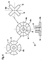
- Fig. 4 are views of a further modified embodiment of the invention shown. It is essential here that the outer magnet armature 56b in its disk-shaped region 76 in the exemplary embodiment has four longitudinal slots 77 offset by 90 ° from one another, into which sections 78 of the inner magnet armature 55b, which are arranged in cross-section in a generally cross-shaped manner. The portions 78 are formed on a pin-shaped portion 79 of the inner armature 55b, which is guided in a through hole of the outer magnetic core 56b. The sections 78 and the disc-shaped region 76 are arranged opposite a (not shown) magnetic coil. That in the Fig.
- a magnet armature assembly 80 is shown in which an outer armature 81 in Flachankerbauweise a disc-shaped portion 82 and a projecting into the portion 46, pin-shaped portion 83 has.
- a first bore portion 84 of relatively large diameter and a second bore portion 85 is formed with respect to the bore portion 84 of reduced diameter.
- the formed as a through hole second bore portion 85 is used together with the first bore portion 84 of the guide of an inner armature 86 in Tauchankerbau way.
- the pin-shaped inner armature 86 which projects partially into the magnetic core 51 c, is provided on the opposite side of the coupler chamber 70 with a Hubbegrenzungselement 87, which cooperates with a first return spring 88, the force is applied to the inner armature 86 in the direction of the coupler space 70.
- the first bore section 84 of the outer magnet armature 81 has a connection bore 89 to connect to the first pressure chamber 18 or can be connected to high-pressure fuel.
- This solution has the advantage that the dimensioning or design of the two end faces 65c, 66c of the two magentankers 81, 86 can be made more independent of the magnetic circuit design, since the hydraulic forces in the transition region between the two bore sections 84, 85 are reduced via the space 90 ,
- a Hubbegrenzungselement 91 is provided, which is designed as a collar on the inner armature 92, and which cooperates with a return spring 93.
- the inner armature 92 except for the Hubbegrenzungselements 91, a pin-shaped or cylindrical shape.
- the outer armature 94 in contrast to the embodiment according to the Fig. 5 no connection hole 89 formed.
- the outer armature 95 is subjected to a force in the direction of the injection valve member 27 by means of a compression spring 96.
- the inner armature 97 has a pin-shaped extension 98 which cooperates with a Hubbegrenzungscopy 99 outside of the magnetic core 51.
- the Hubbegrenzungsusion 99 is subjected to force by means of a compression spring 100, so that via the compression spring 100 on the one hand, the inner magnetic core 97 in the direction of the injection valve member 27 is subjected to force, on the other hand, however, a limitation of the adjustment of the inner magnetic core 97 in the direction of the injection valve member 27 is effected.
- the magnetic circuit can be influenced.
- the characteristic curve of the inner magnet armature 97 by a corresponding geometric dimensioning of the extension 98.
- the outer, designed in Tauchankerbau way armature 101 is sleeve-shaped and protrudes with its upper half into the region of the magnetic coil 102 inside. Further, it has a circumferential collar 103, between which and a front surface of the magnetic core 104, a compression spring 105 is supported. The compression spring 105 thus presses the outer armature 101 in the direction of the injection valve member 27, wherein the movement of the outer armature 101 in the direction of the injection valve member 27 is limited by the circumferential collar 103.
- a cylindrical, also designed in Tauchankerbauweise inner armature 108 is disposed within the outer armature 101.
- the inner armature 108 has on the side facing away from the injection valve member 27 a preferably made of non-magnetic material, designed as a separate component extension 109 which has a Hubbegrenzungsteller 110 outside of the magnetic core 104, on which a return spring 111 is supported, the inner armature 108th in the direction of the injection valve member 27 force. Due to the geometric design of the magnetic core 104 and the magnetic cores 101 and 108, the forces on the armature 101, 108 can be adapted to the requirements. The forces on the outer armature 101 are determined mainly by the compression spring 105 and the magnetic flux 112. On the other hand, forces on the inner armature 108 are substantially determined by the return spring 111 and the magnetic flux 113. Due to the formation of the Federal Circuit 103 and the Hubbegrenzungstellers 110 can be independent strokes of the magenta tankers 101, 108 realize.
- FIG. 9 illustrated embodiment of the invention differs from that in the Fig. 8 illustrated embodiment by an annular elevation 114 on the magnetic core 115, which is arranged in operative connection with the outer armature 101, to influence the characteristic of the outer magnet armature 101.
- annular elevation 114 on the magnetic core 115 which is arranged in operative connection with the outer armature 101, to influence the characteristic of the outer magnet armature 101.
- Fig. 10 illustrated embodiment of the invention differs from that in the Fig. 8 illustrated embodiment in the use of a Hubbegrenzungshunt 117 and a conically shaped portion 118 on the inner armature 108a, which dips into a corresponding stepped bore 119 of the magnetic core 104b. Due to the geometric configuration of the region 118 and the stepped bore 119, the characteristic curve of the inner magnet armature 108a can be influenced.
- the magnet armature arrangements of the Fig. 2 to 10 can be modified or modified in a variety of ways as defined in the appended claims. This consists in the use of at least two mutually independently movable armature, which are arranged longitudinally movable relative to each other and cooperate via a coupler space with an injection valve member.
Landscapes
- Engineering & Computer Science (AREA)
- Physics & Mathematics (AREA)
- Electromagnetism (AREA)
- Chemical & Material Sciences (AREA)
- Combustion & Propulsion (AREA)
- Mechanical Engineering (AREA)
- General Engineering & Computer Science (AREA)
- Fuel-Injection Apparatus (AREA)
Description
- Die Erfindung betrifft einen Kraftstoff-Injektor nach dem Oberbegriff des Anspruchs 1:
- Ein derartiger Kraftstoff-Injektor ist aus der nachveröffentlichten
DE 10 2008 042 227 A1 oder derDE 10 2007 002758 A1 der Anmelderin bekannt. Der bekannte Kraftstoff-Injektor dient zum Einspritzen von Kraftstoff in einen Brennraum einer Brennkraftmaschine und weist ein stiftförmiges Einspritzventilglied auf, das über einen Kopplerraum in Wirkverbindung mit einem Magnetanker angeordnet ist. Der Kopplerraum dient dabei als Kraftübersetzer, der eine Bewegung des Magnetankers in eine Bewegung des Einspritzventilgliedes übersetzt, um damit Einspritzöffnungen am Gehäuse des Kraftstoff-Injektors zu öffnen bzw. zu schließen. Die Kopplung des Magnetankers mit dem Einspritzventilelement über den Kopplerraum findet statt, da die Energiedichte eines Magnetankers bzw. dessen Kraft bei einer direkten mechanischen Kopplung mit dem Einspritzventilglied nicht ausreicht, um das Einspritzventilglied von seinem Dichtsitz abzuheben. Es ist bei dem vorbekannten Kraftstoff-Injektor zwar möglich, durch eine entsprechende Auslegung der geometrischen Verhältnisse von Magentanker, Kopplerraum und Einspritzventilglied die auf das Einspritzventilglied wirkende Öffnungskraft zu erhöhen, jedoch ist dann der maximal mögliche Hub des Einspritzventilglieds für eine ausreichende Funktion des Injektors, d.h. für ein vollständiges Freigeben der Einspritzventilöffnungen, nicht mehr ausreichend. Weiterhin ist festgestellt worden, dass die benötigte Öffnungskraft für das Einspritzventilglied nur solange notwendig ist, solange das Einspritzventilglied noch nicht seinen Dichtsitz am Gehäuse verlassen hat. In diesem Augenblick wird der Raum unter dem Einspritzventilglied mit dem relativ hohen Raildruck beaufschlagt, was zu einer zusätzlichen öffnenden Kraft auf das Einspritzventilglied führt. Hierdurch kann die Kraft, welche durch den Magnetanker auf das Einspritzventilglied aufgebracht wird, reduziert werden. Sobald das Einspritzventilglied den Sitz verlassen hat, muss jedoch sichergestellt sein, dass das Einspritzventilglied einen ausreichend großen Hub zurücklegen kann. - Ausgehend von dem dargestellten Stand der Technik liegt der Erfindung die Aufgabe zugrunde, einen Kraftstoff-Injektor nach dem Oberbegriff des Anspruchs 1 derart weiterzubilden, dass dessen Magnetanker einerseits die erforderliche Öffnungskraft zum Anheben des Einspritzventilglieds von seinem Sitz aufbringt und zum anderen das Einspritzventilglied einen relativ großen Hub ausführen kann. Dabei soll die Baugröße bzw. der Aufwand für den Magnetanker relativ gering sein. Diese Aufgabe wird bei einem Kraftstoff-Injektor mit den Merkmalen des Anspruchs 1 gelöst. Der Erfindung liegt dabei die Idee zugrunde, durch wenigstens zwei relativ zueinander bewegbare Magnetanker, die mit ihren Stirnflächen in den Kopplerraum hineinragen, die von der Magnetspule auf die Magnetankeranordnung übertragbare Kraft auf die beiden Magnetanker derart aufzuteilen, dass ein erster Magnetanker im Wesentlichen für das Abheben des Einspritzventilglieds von seinem Sitz verantwortlich ist, während der andere Magnetanker den erforderlichen, relativ großen Hub des Einspritzventilgliedes ermöglicht.
- Vorteilhafte Weiterbildungen des erfindungsgemäßen Kraftstoff-Injektors sind in den Unteransprüchen angegeben. In den Rahmen der Erfindung fallen sämtliche Kombinationen aus zumindest zwei von in den Ansprüchen, der Beschreibung und/oder den Figuren offenbarten Merkmalen.
- Um einerseits eine relativ einfache Führung der Magnetanker zu erzielen und andererseits Querkräfte auf die Magnetanker bei deren Bewegung zu vermeiden, wird in einer bevorzugten konstruktiven Umsetzung der Erfindung vorgeschlagen, dass die wenigstens zwei Magnetanker konzentrisch zueinander angeordnet sind.
- Hierbei ist es besonders bevorzugt vorgesehen, dass die wenigstens zwei Magnetanker rotationssymmetrisch ausgebildet sind. Dadurch wird insbesondere eine relativ kostengünstige Herstellung der Magentanker ermöglicht.
- Um zu ermöglichen, dass der eine Magnetanker eine möglichst hohe Öffnungskraft im ersten Augenblick auf das Einspritzventilglied ausüben kann, während der andere Magnetanker zur Realisierung eines möglichst großen Hubes des Einspritzventilgliedes nach dessen Öffnung geeignet ist, wird weiterhin vorgeschlagen, dass die in den Köpplerraum hineinragenden Stirnflächen der Magnetanker eine unterschiedliche Größe aufweisen. Hierbei kann durch eine Variation der Größe das gewünschte Öffnungsverhalten beeinflusst bzw. gesteuert werden.
- Da der eine Magnetanker zur Erzielung eine relativ große Öffnungskraft und der andere Magnetanker einen möglichst großen Hub erzielen soll, wird weiterhin vorgeschlagen, dass von zwei Magnetankern die Stirnfläche des inneren Magnetankers eine geringere Fläche aufweist als die Stirnfläche des äußeren Magnetankers. Dadurch wird bei einer konzentrischen Ausbildung der Magnetanker insbesondere eine relativ große Wandstärke des äußeren Mägnetkernbereichs erzielt, was sich fertigungstechnisch relativ einfach realisieren lässt.
- Besonders vorteilhaft ist es hierbei, wenn der äußere Magnetanker eine Führung für den inneren Magnetanker ausbildet. Dadurch wird bei kompaktem Aufbau eine sichere Führung des inneren Magnetankers ermöglicht.
- In einer ersten konstruktiven Umsetzung der Erfindung ist es dabei vorgesehen, dass die Magnetanker jeweils als Flachanker ausgebildet sind. Derartige Flachanker haben den Vorteil, relativ große Anzugskräfte erzielen zu können. Nachteilig hierbei ist jedoch, dass der physikalisch sinnvolle Hub infolge der Bauweise begrenzt ist.
- Daher wird in einer alternativen Ausführungsform der Erfindung vorgeschlagen, dass der äußere Magnetanker als Flachanker und der innere Magnetanker als Tauchanker ausgebildet ist. Ein derartiger Tauchanker weist einen relativ großen Hub auf. Somit lässt sich der erzielbare Hub des inneren Magentankers maximieren.
- In einer weiteren konstruktiven Ausgestaltung ist es auch möglich, beide Magentanker jeweils als Tauchanker auszubilden, so dass besonders große Hübe an beiden Magnetankern erzielt werden können.
- Um den Weg des äußeren Magnetankers zu begrenzen bzw. eine Mitnahme des inneren Magentankers durch den äußeren Magentanker zu ermöglichen, um damit eventuell nur ein Federelement zu benötigen wird weiterhin vorgeschlagen, dass der innere Magnetanker ein Anschlagelement für den äußeren Magnetanker in Öffnungsrichtung des Einspritzventilglieds ausbildet.
- Weitere Vorteile, Merkmale und Einzelheiten der Erfindung ergeben sich aus der nachfolgenden Beschreibung bevorzugter Ausführungsbeispiele sowie anhand der Zeichnungen.
- Diese zeigen in:
- Fig. 1
- eine schematische, geschnittene Darstellung des prinzipiellen Aufbaus eines erfindungsgemäßen Kraftstoff-Injektors, wobei sich dessen Einspritzventilglied in geschlossener Stellung befindet,
- Fig. 2
- einen Teilbereich des Kraftstoff-Injektors gemäß der
Fig. 1 bei einer ersten konstruktiven Ausbildung des Magnetankers mittels zweier Flachanker, - Fig. 3
- eine modifizierte Anordnung gemäß der
Fig. 2 mit einer Hubbegrenzung für den inneren Flachanker, - Fig. 4
- Darstellungen eines modifizierten Magnetankers, bestehend aus zwei Flachankerteilelementen,
- Fig. 5
- eine abgewandelte Ausführung einer Magnetankerbaugruppe in einem Längsschnitt, bei der der innere Magnetanker als Tauchanker ausgebildet ist und eine Anschlagbegrenzung aufweist, während der äußere Magnetanker als Flachanker ausgebildet ist,
- Fig. 6
- eine gegenüber der
Fig. 5 modifizierte Magnetbaugruppe mit einem abgewandelten Anschlag für den inneren Magentanker in geschnittener Darstellung, - Fig. 7
- die Magnetbaugruppe gemäß
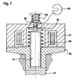
Fig. 6 unter Verwendung eines abgewandelten Anschlagelements für den inneren Magnetanker, - Fig. 8 und 9
- Querschnitte durch jeweils eine modifizierte Magnetankeranordnung, bei der die beiden Magnetanker jeweils als Tauchanker ausgebildet sind und
- Fig. 10
- eine abermals modifizierte Magnetankeranordnung unter Verwendung zweier als Tauchanker ausgebildeter Magnetanker.
- Gleiche Bauteile bzw. Bauteile mit gleicher Funktion sind in den Figuren mit denselben Bezugsziffern versehen.
- In der
Fig. 1 ist schematisch ein als Common-Rail-Injektor ausgebildeter Kraftstoff-Injektor 10 zum Einspritzen von Kraftstoff in einen Brennraum 11 einer nicht gezeigten Brennkraftmaschine dargestellt. Der Kraftstoff-Injektor 10 weist einen Hochdruckanschluss 12 auf, an den eine Versorgungsleitung 13 angeschlossen ist. Über die Versorgungsleitung 13 wird der Kraftstoff-Injektor 10 neben anderen, nicht gezeigten Kraftstoff-Injektoren mit unter Hochdruck (Raildruck) von zum Beispiel über 2000bar stehendem Kraftstoff aus einem Hochdruckspeicher 15 (Rail) versorgt. Der Hochdruckspeicher 15 wiederum wird aus einem Vorratsbehälter 16 (Tank) mit Hilfe einer vorzugsweise als Radialkolbenpumpe ausgebildeten Hochdruckpumpe 17 mit Kraftstoff versorgt. Der Hochdruckanschluss 12 mündet in einen ersten Druckraum 18, der mit im Wesentlichen unter Raildruck stehendem Kraftstoff gefüllt ist. - Der erste Druckraum 18 ist in einem Gehäuse 20 des Kraftstoff-Injektors 10 ausgebildet. In der Längsachse 21 des Kraftstoff-Injektors 10 ist im Gehäuse 20 eine Sacklochbohrung 22 ausgebildet. Die Sacklochbohrung 22 geht von dem ersten Druckraum 18 aus und reicht bis an das dem Brennraum 11 der Brennkraftmaschine zugewandte Ende des Kraftstoff-Injektors 10. Die Sacklochbohrung 22 erweitert sich an ihrem dem Brennraum 11 zugewandten Ende zu einem zweiten Druckraum 24. Im Gehäuse 20 sind weiterhin im Bereich des zweiten Druckraums 24 Düsenlöcher 25 ausgebildet, über die der zweite Druckraum 24 Kraftstoff in den Brennraum 11 der Brennkraftmaschine einspritzt.
- In der Sacklochbohrung 22 ist ein stiftförmiges Einspritzventilglied 27 gleitend geführt, dessen dem Brennraum 11 zugewandtes Ende im Durchmesser vergrößert ausgebildet ist und das mit einer kegelförmigen Fläche 28 mit einem Wandabschnitt des zweiten Druckraums 24 in der Schließstellung des Einspritzventilglieds 27 einen Dichtsitz 29 ausbildet.
- In dem Einspritzventilglied 27 ist eine Längsbohrung 31 als Sacklochbohrung ausgebildet, die über eine Querbohrung 32 in einen ersten, im Gehäuse 20 ausgebildeten Ringraum 33 mündet. Der erste Ringraum 33 ist über eine Verbindungsbohrung 34 mit dem ersten Druckraum 18 verbunden. Zwischen dem ersten Ringraum 33 und dem zweiten Druckraum 24 ist ein zweiter Ringraum 35 im Gehäuse 20 ausgebildet. Der zweite Ringraum 35 hat über eine Entlastungsbohrung 36 mit einer darin angeordneten Drossel 37 Verbindung mit dem Nieder druckbereich des Einspritzsystems, insbesondere mit dem Vorratsbehälter 16.
- Das Einspritzventilglied 27 weist auf der dem ersten Druckraum 18 zugewandten Seite einen Abschnitt 38 mit verringertem Durchmesser auf. Im Bereich des Abschnitts 38 ist das Einspritzventilglied 27 teilweise von einer Druckfeder 39 umgeben, die sich an einer Stirnfläche 41 der Längsbohrung 31 abstützt und die das Einspritzventilglied 27 in Richtung des Dichtsitzes 39 kraftbeaufschlagt. Der Druckfederraum 42, in dem die Druckfeder 39 angeordnet ist, ist weiterhin über eine Querbohrung 43 mit der Verbindungsbohrung 34 gekoppelt und steht somit ebenfalls im Wesentlichen unter Hochdruck (Raildruck).
- Die Sacklochbohrung 22, in der das Einspritzventilglied 27 geführt ist, weist auf der dem ersten Druckraum 18 zugewandten Seite einen im Durchmesser ervveiterten ersten Bohrungsabschnitt 46 auf. Der erste Bohrungsabschnitt 46 geht in einen zweiten Bohrungsabschnitt 47 mit gegenüber dem ersten Bohrungsabschnitt 46 verringertem Durchmesser über, in dem der Abschnitt 38 des Einspritzventilglieds 27 geführt ist.
- Im ersten Druckraum 18 ist eine Magnetankeranordnung 49 angeordnet. Die Magnetankeranordnung 49 ist Teil eines Magnetaktors 50, der einen mit der Magnetankeranordnung 49 zusammenwirkenden Magnetkern 51 mit mittig angeordneter Durchgangsbohrung 52 und im Magnetkern 51 eingebetteter Magnetspule 53 umfasst. Durch eine Bestromung der Magnetspule 53 lässt sich die Magnetankeranordnung 49 in Richtung des Pfeils 54 bewegen, um hiermit ein Öffnen des Einspritzventilglieds 27 zu ermöglichen.
- Bei dem in den
Fig. 1 und2 dargestellten ersten Ausführungsbeispiel der Erfindung weist die Magnetankeranordnung 49 zwei miteinander zusammenwirkende, rotationssymmetrisch ausgebildete Magnetanker 55 und 56 in Flachankerbauweise auf. Der den ersten Magnetanker 55 konzentrisch umgebende zweite Magnetanker 56 weist einen scheibenförmigen Bereich 57 auf, der auf der dem Einspritzventilglied 27 zugewandten Seite in einen hülsen- bzw. stiftförmigen Bereich 58 übergeht. Der Bereich 58 taucht in den ersten Bohrungsabschnitt 46 ein. In der Längsachse des zweiten Magnetankers 56 ist eine Durchgangsbohrung 59 ausgebildet. Die Durchgangsbohrung 59 dient der Führung eines stiftförmigen Abschnitts 61 des inneren, ersten Magnetankers 55, der auf der dem Einspritzventilglied 27 abgewandten Seite einen scheibenförmigen Abschnitt 62 aufweist, der in einer formschlüssig angepassten Ausnehmung 63 des scheibenförmigen Bereichs 57 des zweiten, äußeren Magnetankers 56 unter Bildung eines radial umlaufenden Luftspalts 68 aufgenommen ist. Zwischen dem scheibenförmigen Abschnitt 62 des ersten, inneren Magnetankers 55 und der gegenüberliegenden Wand des Gehäuses 20 stützt sich eine in der Durchgangsbohrung 52 geführte weitere Druckfeder 64 ab, die sowohl den inneren Magnetanker 55 und aufgrund der Anlage des scheibenförmigen Abschnitts 62 des inneren Magnetankers 55 in der Ausnehmung 63 auch den äußeren Magnetanker 56 in Richtung des Einspritzventilglieds 27 kraftbeaufschlagt. - Von den beiden Stirnflächen 65 und 66 des Bereichs 58 bzw. des Abschnitts 61 der beiden Magnetanker 55 und 56, der Stirnfläche 67 des Einspritzventilglieds 27 und den beiden Abschnitten 46, 47 der Sacklochbohrung 22 wird ein Koppler raum 70 ausgebildet. Der mit unter Hochdruck stehendem Kraftstoff gefüllte Kopplerraum 70 dient der Übertragung einer Bewegung der beiden Magnetanker 55, 56 in eine entsprechende Bewegung des Einspritzventilglieds 27.
- Im dargestellten Ausführungsbeispiel ist es vorgesehen, die Stirnfläche 66 des inneren Magnetankers 55 kleiner als die Stirnfläche 67 des Einspritzventilglieds 27 auszubilden, um damit eine größere Kraftübersetzung bei einer Bewegung des inneren Magentankers 55 zu ermöglichen. Da das Volumen des Kopplerraums 70 bei einer Bewegung der Magnetanker 55, 56 konstant bleibt, bedeutet dies, dass aufgrund der unterschiedlichen Größen der Stirnflächen 66 und 67 ein relativ großer Hub des inneren Magnetankers 55 in einen relativ kleinen Hub des Einspritzventilglieds 27 übersetzt wird. Mit anderen Worten gesagt bedeutet dies, dass bereits mit einer geringen, in Richtung des Pfeils 54 wirkenden Kraft auf den inneren Magnetanker 55 aufgrund einer Bestromung der Magnetspule 53 sich eine relativ große Öffnungskraft am Einspritzventilglied 27 bzw. an dessen Dichtsitz 29 realisieren lässt.
- Bei einer Bestromung der Magnetspule 53 bewegt sich zunächst der innere Magnetanker 55 in Richtung des Pfeils 54, während der äußere Magnetanker 56 im ersten Augenblick in Ruhe verbleibt. Sobald das Einspritzventilglied 27 von seinem Dichtsitz 29 abhebt bewegt sich auch der äußere Magnetanker 56 in Richtung der Magnetspule 53, wobei durch die relativ große Fläche der Stirnfläche 65 (im Vergleich zur Stirnfläche 66) auch ein relativ großer nachfolgender Hub des Einspritzventilglieds 27 in Öffnungsrichtung erfolgt. Somit lässt sich nach dem erfolgten Abheben des Einspritzventilglieds 27 von dem Dichtsitz 29 infolge der Bewegung des inneren Magnetankers 55 mittels des äußeren Magentankers 56 ein relativ großer Hub des Einspritzventilglieds 27 erzeugen.
- In der
Fig. 3 ist ein gegenüber denFig. 1 und2 abgewandeltes Ausführungsbeispiel der Erfindung dargestellt. Hierbei weist der äußere Magnetanker 56a auf der der Magnetspule 53 zugewandten Seite an seinem äußeren Bereich eine radial umlaufende Stufe 71 auf. Zwischen der Stufe 71 und der gegenüberliegenden Stirnfläche des Magnetkerns 51 stützt sich eine erste Rückstellfeder 74 ab. Die erste Rückstellfeder 74 drückt somit den äußeren Magnetanker 56a in Richtung des Einspritzventilglieds 27. Weiterhin weist der innere Magnetanker 55a eine stiftartige Verlängerung 72 auf, die die Durchgangsbohrung 52 des Magnetkerns 51 durchsetzt. Auf der dem Einspritzventilglied 27 abgewandten Seite des inneren Magnetankers 55a schließt sich an die Verlängerung 72 ein tellerförmiger Bereich 73 an, auf den eine zweite Rückstellfeder 75 wirkt. Mittels der zweiten Rückstellfeder 75 wird der innere Magnetanker 55a ebenfalls in Richtung des Einspritzventilglieds 27 kraftbeaufschlagt, wobei der tellerförmige Bereich 73, wenn er an der dem Einspritzventilglied 27 gegenüberliegenden Seite des Magnetkerns 51 anliegt, eine Hubbegrenzung für den inneren Magnetanker 55a in Richtung des Einspritzventilglieds 27 ausbildet. Mittels einer derartigen Ausbildung lässt sich am äußeren Magnetanker 56a ein größerer Hub verwirklichen als am inneren Magnetanker 55a. - In der
Fig. 4 sind Ansichten eines weiteren, abgewandelten Ausführungsbeispiels der Erfindung dargestellt. Wesentlich hierbei ist, dass der äußere Magnetanker 56b in seinem scheibenförmigen Bereich 76 im Ausführungsbeispiel vier, um jeweils 90° zueinander versetzt angeordnete Längsschlitze 77 aufweist, in die im Querschnitt insgesamt kreuzförmig angeordnete Abschnitte 78 des inneren Magnetankers 55b hineinragen. Die Abschnitte 78 sind an einem stiftförmigen Abschnitt 79 des inneren Magnetankers 55b ausgebildet, der in einer Durchgangsbohrung des äußeren Magnetkerns 56b geführt ist. Die Abschnitte 78 sowie der scheibenförmige Bereich 76 sind gegenüber einer (nicht dargestellten) Magnetspule angeordnet. Das in derFig. 4 dargestellte Ausführungsbeispiel hat den Vorteil, dass die magnetischen Flüsse durch die beiden Magnetanker 55b, 56b unabhängig voneinander sind, das heißt, dass der magentische Fluss jeweils nur durch einen der Magnetanker 55b, 56b fließen kann. Somit entfällt ein parasitärer Luftspalt, wie er beispielhaft in derFig. 3 zwischen den beiden Magnetankern 55a und 56a vorhanden ist. - In der
Fig. 5 ist eine Magnetankeranordnung 80 dargestellt, bei der ein äußerer Magnetanker 81 in Flachankerbauweise einen scheibenförmigen Bereich 82 sowie einen in den Abschnitt 46 hineinragenden, stiftförmigen Abschnitt 83 aufweist. In dem äußeren Magnetanker 81 ist ein erster Bohrungsabschnitt 84 mit relativ großem Durchmesser und ein zweiter Bohrungsabschnitt 85 mit gegenüber dem Bohrungsabschnitt 84 verringertem Durchmesser ausgebildet. Der als Durchgangsbohrung ausgebildete zweite Bohrungsabschnitt 85 dient zusammen mit dem ersten Bohrungsabschnitt 84 der Führung eines inneren Magnetankers 86 in Tauchankerbauweise. Der stiftförmige innere Magnetanker 86, der teilweise in den Magnetkern 51 c hineinragt, ist auf der dem Kopplerraum 70 gegenüberliegenden Seite mit einem Hubbegrenzungselement 87 versehen, das mit einer ersten Rückstellfeder 88 zusammenwirkt, die den inneren Magnetanker 86 in Richtung des Kopplerraums 70 kraftbeaufschlagt. Wesentlich ist, dass der erste Bohrungsabschnitt 84 des äußeren Magnetankers 81 über eine Verbindungsbohrung 89 Verbindung mit dem ersten Druckraum 18 hat bzw. mit unter Hochdruck stehendem Kraftstoff verbindbar ist. Beim Abheben des inneren Magnetankers 86 wird somit im Bereich des ersten Bohrungsabschnitts 84 ein ringförmiger Raum 90 gebildet, der mit Kraftstoff befüllt wird. Diese Lösung hat den Vorteil, dass die Dimensionierung bzw. Auslegung der beiden Stirnflächen 65c, 66c der beiden Magentanker 81, 86 unabhängiger von der Magnetkreisauslegung erfolgen kann, da über den Raum 90 die hydraulischen Kräfte im Übergangsbereich zwischen den beiden Bohrungsabschnitten 84, 85 vermindert werden. - Das in der
Fig. 6 dargestellte Ausführungsbeispiel der Erfindung unterscheidet sich von dem in derFig. 5 dargestellten Ausführungsbeispiel im Wesentlichen dadurch, dass ein Hubbegrenzungselement 91 vorgesehen ist, das als Bund am inneren Magnetanker 92 ausgebildet ist, und das mit einer Rückstellfeder 93 zusammenwirkt. Ferner weist der innere Magnetanker 92, mit Ausnahme des Hubbegrenzungselements 91, eine stiftförmige bzw. zylindrische Form auf. Weiterhin ist am äußeren Magnetanker 94 im Gegensatz zur Ausführungsform gemäß derFig. 5 keine Verbindungsbohrung 89 ausgebildet. Diese Lösung hat den Vorteil, dass im Vergleich zur Ausführung gemäß derFig. 5 auf die Rückstellfeder 88 und das (separate) Hubbegrenzungselement 87 verzichtet werden kann. Es ist jedoch nun (im Vergleich zurFig. 5 ) nur noch eine begrenzte unabhängige Bewegung der beiden Magrietanker 92, 94 möglich. - Bei dem Ausführungsbeispiel gemäß der
Fig. 7 wird der äußere Magnetanker 95 mittels einer Druckfeder 96 in Richtung des Einspritzventilglieds 27 kraftbeaufschlagt. Der innere Magnetanker 97 weist eine stiftförmige Verlängerung 98 auf, die außerhalb des Magnetkerns 51 mit einer Hubbegrenzungsscheibe 99 zusammenwirkt. Die Hubbegrenzungsscheibe 99 ist mittels einer Druckfeder 100 kraftbeaufschlagt, sodass über die Druckfeder 100 einerseits der innere Magnetkern 97 in Richtung des Einspritzventilglieds 27 kraftbeaufschlagt wird, andererseits jedoch eine Begrenzung des Verstellweges des inneren Magnetkerns 97 in Richtung des Einspritzventilgliedes 27 bewirkt wird. Durch die stiftförmige Verlängerung 98 des inneren Magnetankers 97, die aus magnetischem Material besteht, kann der Magnetkreis beeinflusst werden. Insbesondere kann durch eine entsprechende geometrische Dimensionierung der Verlängerung 98 eine Beeinflussung der Kennlinie des inneren Magnetankers 97 ermöglicht werden. - Bei dem in der
Fig. 8 dargestellten Ausführungsbeispiel der Erfindung ist der äußere, in Tauchankerbauweise ausgeführte Magnetanker 101 hülsenförmig ausgebildet und ragt mit seiner oberen Hälfte in den Bereich der Magnetspule 102 hinein. Ferner weist er einen Umfangsbund 103 auf, zwischen dem und einer Stirnfläche des Magnetkerns 104 sich eine Druckfeder 105 abstützt. Die Druckfeder 105 drückt den äußeren Magnetanker 101 somit in Richtung des Einspritzventilglieds 27, wobei die Bewegung des äußeren Magnetankers 101 in Richtung des Einspritzventilglieds 27 durch den Umfangsbund 103 begrenzt ist. Innerhalb des äußeren Magnetankers 101 ist ein zylindrischer, ebenfalls in Tauchankerbauweise ausgebildeter innerer Magnetanker 108 angeordnet. Der innere Magnetanker 108 besitzt auf der dem Einspritzventilglied 27 abgewandten Seite eine vorzugsweise aus nicht magnetischem Material bestehende, als separates Bauteil ausgebildete Verlängerung 109, die außerhalb des Magnetkerns 104 einen Hubbegrenzungsteller 110 aufweist, an dem sich eine Rückstellfeder 111 stützt, die den inneren Magnetanker 108 in Richtung des Einspritzventilglieds 27 kraftbeaufschlagt. Durch die geometrische Gestaltung des Magnetkerns 104 sowie der Magnetkerne 101 und 108 können die Kräfte auf die Magnetanker 101, 108 den Anforderungen angepasst werden. Die Kräfte auf den äußeren Magnetanker 101 werden dabei hauptsächlich durch die Druckfeder 105 und den magnetischen Fluss 112 bestimmt. Demgegenüber werden Kräfte auf den inneren Magnetanker 108 im Wesentlichen durch die Rückstellfeder 111 und den magnetischen Fluss 113 bestimmt. Durch die Ausbildung des Umfangbundes 103 und des Hubbegrenzungstellers 110 lassen sich unabhängige Hübe der Magentanker 101, 108 verwirklichen. - Das in der
Fig. 9 dargestellte Ausführungsbeispiel der Erfindung unterscheidet sich von dem in derFig. 8 dargestellten Ausführungsbeispiel durch eine ringförmige Erhebung 114 am Magnetkern 115, die in Wirkverbindung mit dem äußeren Magnetanker 101 angeordnet ist, um die Kennlinie des äußeren Magentankers 101 zu beeinflussen. Ergänzend wird erwähnt, dass durch entsprechende Gestaltung des Magnetkerns 115 auch eine Beeinflussung des inneren Magentankers 108 bzw. an beiden Magnetankern 101, 108 möglich ist. - Das in der
Fig. 10 dargestellte Ausführungsbeispiel der Erfindung unterscheidet sich von dem in derFig. 8 dargestellten Ausführungsbeispiel in der Verwendung einer Hubbegrenzungsscheibe 117 sowie einem kegelförmig ausgebildeten Bereich 118 am inneren Magnetanker 108a, der in eine entsprechende Stufenbohrung 119 des Magnetkerns 104b eintaucht. Durch die geometrische Gestaltung des Bereichs 118 und der Stufenbohrung 119 lässt sich die Kennlinie des inneren Magnetankers 108a beeinflussen. - Die soweit beschriebenen Magnetankeranordnungen der
Fig. 2 bis 10 können in vielfältiger Art und Weise abgewandelt bzw. modifiziert werden, wie in angehängten Ansprüche definiert. Dieser besteht in der Verwendung mindestens zweier voneinander unabhängig bewegbarer Magnetanker, die längsbeweglich zueinander angeordnet sind und über einen Kopplerraum mit einem Einspritzventilglied zusammenwirken.
Claims (10)
- Kraftstoff-Injektor (10), insbesondere Common-Rail-Injektor, zum Einspritzen von Kraftstoff in einen Brennraum (11) einer Brennkraftmaschine, mit einem zwischen einer Schließstellung und einer eine Düsenlochanordnung (25) freigebenden Öffnungsstellung verstellbaren Einspritzventilelement (27), wobei das Einspritzventilelement (27) über einen mit Druckmittel befüllten Kopplerraum (70) von einer Magnetankeranordnung (49; 80) ansteuerbar ist,
dadurch gekennzeichnet,
dass der Magnetankeranordnung (49; 80) wenigstens zwei relativ zueinander beweglich angeordnete Magnetanker (55, 55a, 55b, 56, 56a, 56b, 81, 86, 92, 94, 95, 97, 101, 108, 108a) aufweist, die mit ihren Stirnflächen (65, 6c, 66, 66c) in den Koppelraum (70) hineinragen. - Kraftstoff-Injektor nach Anspruch 1,
dadurch gekennzeichnet,
dass die wenigstens zwei Magnetanker (55, 55a, 55b, 56, 56a, 56b, 81, 86, 92, 94, 95, 97, 101, 108, 108a) konzentrisch zueinander angeordnet sind. - Kraftstoff-Injektor nach Anspruch 2,
dadurch gekennzeichnet,
dass die wenigstens zwei Magnetanker (55, 55a, 55b, 56, 56a, 56b, 81, 86, 92, 94, 95, 97, 101, 108, 108a) rotationssymmetrisch ausgebildet sind. - Kraftstoff-Injektor nach Anspruch 2 oder 3,
dadurch gekennzeichnet,
dass die in den Kopplerraum (70) hineinragenden Stirnflächen (65, 6c, 66, 66c) der Magnetanker (55, 55a, 55b, 56, 56a, 56b, 81, 86, 92, 94, 95, 97, 101, 108, 108a) eine unterschiedliche Größe aufweisen. - Kraftstoff-Injektor nach Anspruch 4,
dadurch gekennzeichnet,
dass bei zwei Magnetankern (55, 56, 81, 86) die Stimfläche (66, 66c) des inneren Magnetankers (55, 86) eine geringere Fläche aufweist als die Stirnfläche (65, 65c) des äußeren Magnetankers (56, 81). - Kraftstoff-Injektor nach einem der Ansprüche 2 bis 5,
dadurch gekennzeichnet,
dass der äußere Magnetanker (56, 56a, 56b, 81, 94, 95,101) eine Führung für den inneren Magnetanker (55, 55a, 55b, 86, 92, 97, 108, 108a) ausbildet. - Kraftstoff-Injektor nach einem der Ansprüche 3 bis 6,
dadurch gekennzeichnet,
dass die Magnetanker (55, 55a, 55b, 56, 56a, 56b) der Magnetankeranordnung (49) als Flachanker ausgebildet sind. - Kraftstoff-Injektor nach einem der Ansprüche 3 bis 6,
dadurch gekennzeichnet,
dass bei zwei Magnetankern (81, 86, 92, 94, 95, 97) der äußere Magnetanker (81, 94, 95) als Flachanker und der innere Magnetanker (86, 92, 97) als Tauchanker ausgebildet ist. - Kraftstoff-Injektor nach einem der Ansprüche 3 bis 6,
dadurch gekennzeichnet,
dass bei zwei Magnetankern (101, 108, 108a) beide Magnetanker (101, 108, 108a) als Tauchanker ausgebildet sind. - Kraftstoff-Injektor nach einem der Ansprüche 7 bis 9,
dadurch gekennzeichnet,
dass der innere Magnetanker (55, 55a, 55b, 86) ein Anschlagelement für den äußeren Magnetanker (56, 56a, 56b, 81) in Öffnungsrichtung des Einspritzventilglieds (27) ausbildet.
Applications Claiming Priority (2)
| Application Number | Priority Date | Filing Date | Title |
|---|---|---|---|
| DE201010002845 DE102010002845A1 (de) | 2010-03-15 | 2010-03-15 | Kraftstoff-Injektor |
| PCT/EP2011/051628 WO2011113640A1 (de) | 2010-03-15 | 2011-02-04 | Kraftstoff-injektor |
Publications (2)
| Publication Number | Publication Date |
|---|---|
| EP2547895A1 EP2547895A1 (de) | 2013-01-23 |
| EP2547895B1 true EP2547895B1 (de) | 2014-09-10 |
Family
ID=43837896
Family Applications (1)
| Application Number | Title | Priority Date | Filing Date |
|---|---|---|---|
| EP11702983.5A Not-in-force EP2547895B1 (de) | 2010-03-15 | 2011-02-04 | Kraftstoff-injektor |
Country Status (5)
| Country | Link |
|---|---|
| EP (1) | EP2547895B1 (de) |
| CN (1) | CN102792003B (de) |
| DE (1) | DE102010002845A1 (de) |
| RU (1) | RU2555066C2 (de) |
| WO (1) | WO2011113640A1 (de) |
Families Citing this family (3)
| Publication number | Priority date | Publication date | Assignee | Title |
|---|---|---|---|---|
| JP6186126B2 (ja) * | 2013-01-24 | 2017-08-23 | 日立オートモティブシステムズ株式会社 | 燃料噴射装置 |
| EP2863044B1 (de) * | 2013-10-15 | 2016-06-29 | Continental Automotive GmbH | Einspritzventil |
| CN114151255B (zh) * | 2021-11-19 | 2023-02-14 | 哈尔滨工程大学 | 电磁阀直驱喷油-增压双作用喷油器 |
Family Cites Families (7)
| Publication number | Priority date | Publication date | Assignee | Title |
|---|---|---|---|---|
| SU1236140A1 (ru) * | 1983-06-01 | 1986-06-07 | Bukhvalov Vladimir V | Электромагнитна форсунка |
| JP2001522140A (ja) * | 1997-11-03 | 2001-11-13 | ディーゼル エンジン リターダーズ,インコーポレイテッド | カスケード電磁アーマチュア |
| CN2761860Y (zh) * | 2003-10-15 | 2006-03-01 | 中国第一汽车集团公司 | 电子控制喷油器 |
| DE102004035280A1 (de) * | 2004-07-21 | 2006-03-16 | Robert Bosch Gmbh | Kraftstoffinjektor mit direkter mehrstufiger Einspritzventilgliedansteuerung |
| DE102007002758A1 (de) * | 2006-04-04 | 2007-10-11 | Robert Bosch Gmbh | Kraftstoffinjektor |
| DE102006020689A1 (de) * | 2006-05-04 | 2007-11-08 | Robert Bosch Gmbh | Magnetventil mit stoffschlüssiger Ankerverbindung |
| DE102008042227A1 (de) | 2008-09-19 | 2010-04-01 | Robert Bosch Gmbh | Kraftstoff-Injektor |
-
2010
- 2010-03-15 DE DE201010002845 patent/DE102010002845A1/de not_active Withdrawn
-
2011
- 2011-02-04 RU RU2012143687/06A patent/RU2555066C2/ru not_active IP Right Cessation
- 2011-02-04 EP EP11702983.5A patent/EP2547895B1/de not_active Not-in-force
- 2011-02-04 CN CN201180014128.8A patent/CN102792003B/zh not_active Expired - Fee Related
- 2011-02-04 WO PCT/EP2011/051628 patent/WO2011113640A1/de not_active Ceased
Also Published As
| Publication number | Publication date |
|---|---|
| CN102792003A (zh) | 2012-11-21 |
| EP2547895A1 (de) | 2013-01-23 |
| RU2012143687A (ru) | 2014-04-20 |
| DE102010002845A1 (de) | 2011-09-15 |
| CN102792003B (zh) | 2015-06-17 |
| WO2011113640A1 (de) | 2011-09-22 |
| RU2555066C2 (ru) | 2015-07-10 |
Similar Documents
| Publication | Publication Date | Title |
|---|---|---|
| EP2499350A1 (de) | Verfahren zum herstellen eines kraftstoffeinspritzventils und kraftstoffeinspritzventil | |
| EP1756415B1 (de) | Kraftstoffinjektor mit variabler aktorübersetzung | |
| EP2670970B1 (de) | Kraftstoffinjektor | |
| EP2428672A2 (de) | Kraftstoffinjektor | |
| EP1853813B1 (de) | Einspritzdüse | |
| EP2547895A1 (de) | Kraftstoff-injektor | |
| DE102012201413A1 (de) | Magnetventil für einen Kraftstoffinjektor | |
| DE102010041109A1 (de) | Kraftstoffinjektor | |
| DE102013226776A1 (de) | Kraftstoffinjektor | |
| EP2204570B1 (de) | Kraftstoff-Injektor | |
| EP1961953A1 (de) | Mehrwegeventil | |
| WO2011023473A1 (de) | Injektor zum einspritzen von kraftstoff | |
| DE102008041553A1 (de) | Kraftstoff-Injektor | |
| WO2014206766A1 (de) | Magnetventil und kraftstoffinjektor mit einem magnetventil | |
| DE102012224247A1 (de) | Kraftstoffinjektor und dessen Verwendung | |
| EP3095998B1 (de) | Kraftstoffinjektor | |
| WO2015058929A1 (de) | Kraftstoffinjektor | |
| DE102010040323A1 (de) | Kraftstoffinjektor | |
| DE102011076956A1 (de) | Kraftstoffinjektor | |
| WO2009138279A1 (de) | Magnetventil mit ankerschlitzung | |
| EP2366887B1 (de) | Kraftstoffinjektor | |
| DE102013210744A1 (de) | Kraftstoffinjektor | |
| EP3098433B1 (de) | Kraftstoffinjektor | |
| EP3303817B1 (de) | Common-rail-injektor | |
| WO2017067715A1 (de) | Elektromagnetisch betätigbares einlassventil und hochdruckpumpe mit einlassventil |
Legal Events
| Date | Code | Title | Description |
|---|---|---|---|
| PUAI | Public reference made under article 153(3) epc to a published international application that has entered the european phase |
Free format text: ORIGINAL CODE: 0009012 |
|
| 17P | Request for examination filed |
Effective date: 20121015 |
|
| AK | Designated contracting states |
Kind code of ref document: A1 Designated state(s): AL AT BE BG CH CY CZ DE DK EE ES FI FR GB GR HR HU IE IS IT LI LT LU LV MC MK MT NL NO PL PT RO RS SE SI SK SM TR |
|
| DAX | Request for extension of the european patent (deleted) | ||
| GRAJ | Information related to disapproval of communication of intention to grant by the applicant or resumption of examination proceedings by the epo deleted |
Free format text: ORIGINAL CODE: EPIDOSDIGR1 |
|
| GRAP | Despatch of communication of intention to grant a patent |
Free format text: ORIGINAL CODE: EPIDOSNIGR1 |
|
| INTG | Intention to grant announced |
Effective date: 20140402 |
|
| INTC | Intention to grant announced (deleted) | ||
| GRAP | Despatch of communication of intention to grant a patent |
Free format text: ORIGINAL CODE: EPIDOSNIGR1 |
|
| GRAJ | Information related to disapproval of communication of intention to grant by the applicant or resumption of examination proceedings by the epo deleted |
Free format text: ORIGINAL CODE: EPIDOSDIGR1 |
|
| GRAP | Despatch of communication of intention to grant a patent |
Free format text: ORIGINAL CODE: EPIDOSNIGR1 |
|
| INTG | Intention to grant announced |
Effective date: 20140509 |
|
| INTG | Intention to grant announced |
Effective date: 20140604 |
|
| GRAS | Grant fee paid |
Free format text: ORIGINAL CODE: EPIDOSNIGR3 |
|
| GRAA | (expected) grant |
Free format text: ORIGINAL CODE: 0009210 |
|
| AK | Designated contracting states |
Kind code of ref document: B1 Designated state(s): AL AT BE BG CH CY CZ DE DK EE ES FI FR GB GR HR HU IE IS IT LI LT LU LV MC MK MT NL NO PL PT RO RS SE SI SK SM TR |
|
| REG | Reference to a national code |
Ref country code: GB Ref legal event code: FG4D Free format text: NOT ENGLISH |
|
| REG | Reference to a national code |
Ref country code: CH Ref legal event code: EP |
|
| REG | Reference to a national code |
Ref country code: IE Ref legal event code: FG4D Free format text: LANGUAGE OF EP DOCUMENT: GERMAN |
|
| REG | Reference to a national code |
Ref country code: AT Ref legal event code: REF Ref document number: 686829 Country of ref document: AT Kind code of ref document: T Effective date: 20141015 |
|
| REG | Reference to a national code |
Ref country code: DE Ref legal event code: R096 Ref document number: 502011004323 Country of ref document: DE Effective date: 20141023 |
|
| PG25 | Lapsed in a contracting state [announced via postgrant information from national office to epo] |
Ref country code: SE Free format text: LAPSE BECAUSE OF FAILURE TO SUBMIT A TRANSLATION OF THE DESCRIPTION OR TO PAY THE FEE WITHIN THE PRESCRIBED TIME-LIMIT Effective date: 20140910 Ref country code: FI Free format text: LAPSE BECAUSE OF FAILURE TO SUBMIT A TRANSLATION OF THE DESCRIPTION OR TO PAY THE FEE WITHIN THE PRESCRIBED TIME-LIMIT Effective date: 20140910 Ref country code: GR Free format text: LAPSE BECAUSE OF FAILURE TO SUBMIT A TRANSLATION OF THE DESCRIPTION OR TO PAY THE FEE WITHIN THE PRESCRIBED TIME-LIMIT Effective date: 20141211 Ref country code: LT Free format text: LAPSE BECAUSE OF FAILURE TO SUBMIT A TRANSLATION OF THE DESCRIPTION OR TO PAY THE FEE WITHIN THE PRESCRIBED TIME-LIMIT Effective date: 20140910 Ref country code: NO Free format text: LAPSE BECAUSE OF FAILURE TO SUBMIT A TRANSLATION OF THE DESCRIPTION OR TO PAY THE FEE WITHIN THE PRESCRIBED TIME-LIMIT Effective date: 20141210 Ref country code: ES Free format text: LAPSE BECAUSE OF FAILURE TO SUBMIT A TRANSLATION OF THE DESCRIPTION OR TO PAY THE FEE WITHIN THE PRESCRIBED TIME-LIMIT Effective date: 20140910 |
|
| REG | Reference to a national code |
Ref country code: NL Ref legal event code: VDEP Effective date: 20140910 |
|
| REG | Reference to a national code |
Ref country code: LT Ref legal event code: MG4D |
|
| PG25 | Lapsed in a contracting state [announced via postgrant information from national office to epo] |
Ref country code: CY Free format text: LAPSE BECAUSE OF FAILURE TO SUBMIT A TRANSLATION OF THE DESCRIPTION OR TO PAY THE FEE WITHIN THE PRESCRIBED TIME-LIMIT Effective date: 20140910 Ref country code: HR Free format text: LAPSE BECAUSE OF FAILURE TO SUBMIT A TRANSLATION OF THE DESCRIPTION OR TO PAY THE FEE WITHIN THE PRESCRIBED TIME-LIMIT Effective date: 20140910 Ref country code: RS Free format text: LAPSE BECAUSE OF FAILURE TO SUBMIT A TRANSLATION OF THE DESCRIPTION OR TO PAY THE FEE WITHIN THE PRESCRIBED TIME-LIMIT Effective date: 20140910 Ref country code: LV Free format text: LAPSE BECAUSE OF FAILURE TO SUBMIT A TRANSLATION OF THE DESCRIPTION OR TO PAY THE FEE WITHIN THE PRESCRIBED TIME-LIMIT Effective date: 20140910 |
|
| PG25 | Lapsed in a contracting state [announced via postgrant information from national office to epo] |
Ref country code: NL Free format text: LAPSE BECAUSE OF FAILURE TO SUBMIT A TRANSLATION OF THE DESCRIPTION OR TO PAY THE FEE WITHIN THE PRESCRIBED TIME-LIMIT Effective date: 20140910 |
|
| PG25 | Lapsed in a contracting state [announced via postgrant information from national office to epo] |
Ref country code: CZ Free format text: LAPSE BECAUSE OF FAILURE TO SUBMIT A TRANSLATION OF THE DESCRIPTION OR TO PAY THE FEE WITHIN THE PRESCRIBED TIME-LIMIT Effective date: 20140910 Ref country code: PT Free format text: LAPSE BECAUSE OF FAILURE TO SUBMIT A TRANSLATION OF THE DESCRIPTION OR TO PAY THE FEE WITHIN THE PRESCRIBED TIME-LIMIT Effective date: 20150112 Ref country code: SK Free format text: LAPSE BECAUSE OF FAILURE TO SUBMIT A TRANSLATION OF THE DESCRIPTION OR TO PAY THE FEE WITHIN THE PRESCRIBED TIME-LIMIT Effective date: 20140910 Ref country code: RO Free format text: LAPSE BECAUSE OF FAILURE TO SUBMIT A TRANSLATION OF THE DESCRIPTION OR TO PAY THE FEE WITHIN THE PRESCRIBED TIME-LIMIT Effective date: 20140910 Ref country code: IS Free format text: LAPSE BECAUSE OF FAILURE TO SUBMIT A TRANSLATION OF THE DESCRIPTION OR TO PAY THE FEE WITHIN THE PRESCRIBED TIME-LIMIT Effective date: 20150110 Ref country code: EE Free format text: LAPSE BECAUSE OF FAILURE TO SUBMIT A TRANSLATION OF THE DESCRIPTION OR TO PAY THE FEE WITHIN THE PRESCRIBED TIME-LIMIT Effective date: 20140910 |
|
| PG25 | Lapsed in a contracting state [announced via postgrant information from national office to epo] |
Ref country code: PL Free format text: LAPSE BECAUSE OF FAILURE TO SUBMIT A TRANSLATION OF THE DESCRIPTION OR TO PAY THE FEE WITHIN THE PRESCRIBED TIME-LIMIT Effective date: 20140910 |
|
| REG | Reference to a national code |
Ref country code: DE Ref legal event code: R097 Ref document number: 502011004323 Country of ref document: DE |
|
| PG25 | Lapsed in a contracting state [announced via postgrant information from national office to epo] |
Ref country code: BE Free format text: LAPSE BECAUSE OF NON-PAYMENT OF DUE FEES Effective date: 20150228 |
|
| PLBE | No opposition filed within time limit |
Free format text: ORIGINAL CODE: 0009261 |
|
| STAA | Information on the status of an ep patent application or granted ep patent |
Free format text: STATUS: NO OPPOSITION FILED WITHIN TIME LIMIT |
|
| PG25 | Lapsed in a contracting state [announced via postgrant information from national office to epo] |
Ref country code: DK Free format text: LAPSE BECAUSE OF FAILURE TO SUBMIT A TRANSLATION OF THE DESCRIPTION OR TO PAY THE FEE WITHIN THE PRESCRIBED TIME-LIMIT Effective date: 20140910 |
|
| 26N | No opposition filed |
Effective date: 20150611 |
|
| PG25 | Lapsed in a contracting state [announced via postgrant information from national office to epo] |
Ref country code: LU Free format text: LAPSE BECAUSE OF FAILURE TO SUBMIT A TRANSLATION OF THE DESCRIPTION OR TO PAY THE FEE WITHIN THE PRESCRIBED TIME-LIMIT Effective date: 20150204 |
|
| REG | Reference to a national code |
Ref country code: CH Ref legal event code: PL |
|
| GBPC | Gb: european patent ceased through non-payment of renewal fee |
Effective date: 20150204 |
|
| PG25 | Lapsed in a contracting state [announced via postgrant information from national office to epo] |
Ref country code: CH Free format text: LAPSE BECAUSE OF NON-PAYMENT OF DUE FEES Effective date: 20150228 Ref country code: MC Free format text: LAPSE BECAUSE OF FAILURE TO SUBMIT A TRANSLATION OF THE DESCRIPTION OR TO PAY THE FEE WITHIN THE PRESCRIBED TIME-LIMIT Effective date: 20140910 Ref country code: LI Free format text: LAPSE BECAUSE OF NON-PAYMENT OF DUE FEES Effective date: 20150228 |
|
| REG | Reference to a national code |
Ref country code: IE Ref legal event code: MM4A |
|
| PG25 | Lapsed in a contracting state [announced via postgrant information from national office to epo] |
Ref country code: SI Free format text: LAPSE BECAUSE OF FAILURE TO SUBMIT A TRANSLATION OF THE DESCRIPTION OR TO PAY THE FEE WITHIN THE PRESCRIBED TIME-LIMIT Effective date: 20140910 |
|
| PG25 | Lapsed in a contracting state [announced via postgrant information from national office to epo] |
Ref country code: GB Free format text: LAPSE BECAUSE OF NON-PAYMENT OF DUE FEES Effective date: 20150204 Ref country code: IE Free format text: LAPSE BECAUSE OF NON-PAYMENT OF DUE FEES Effective date: 20150204 |
|
| REG | Reference to a national code |
Ref country code: FR Ref legal event code: PLFP Year of fee payment: 6 |
|
| PG25 | Lapsed in a contracting state [announced via postgrant information from national office to epo] |
Ref country code: MT Free format text: LAPSE BECAUSE OF FAILURE TO SUBMIT A TRANSLATION OF THE DESCRIPTION OR TO PAY THE FEE WITHIN THE PRESCRIBED TIME-LIMIT Effective date: 20140910 |
|
| REG | Reference to a national code |
Ref country code: FR Ref legal event code: PLFP Year of fee payment: 7 |
|
| REG | Reference to a national code |
Ref country code: AT Ref legal event code: MM01 Ref document number: 686829 Country of ref document: AT Kind code of ref document: T Effective date: 20160204 |
|
| PG25 | Lapsed in a contracting state [announced via postgrant information from national office to epo] |
Ref country code: HU Free format text: LAPSE BECAUSE OF FAILURE TO SUBMIT A TRANSLATION OF THE DESCRIPTION OR TO PAY THE FEE WITHIN THE PRESCRIBED TIME-LIMIT; INVALID AB INITIO Effective date: 20110204 Ref country code: BG Free format text: LAPSE BECAUSE OF FAILURE TO SUBMIT A TRANSLATION OF THE DESCRIPTION OR TO PAY THE FEE WITHIN THE PRESCRIBED TIME-LIMIT Effective date: 20140910 Ref country code: SM Free format text: LAPSE BECAUSE OF FAILURE TO SUBMIT A TRANSLATION OF THE DESCRIPTION OR TO PAY THE FEE WITHIN THE PRESCRIBED TIME-LIMIT Effective date: 20140910 Ref country code: AT Free format text: LAPSE BECAUSE OF NON-PAYMENT OF DUE FEES Effective date: 20160204 |
|
| PG25 | Lapsed in a contracting state [announced via postgrant information from national office to epo] |
Ref country code: TR Free format text: LAPSE BECAUSE OF FAILURE TO SUBMIT A TRANSLATION OF THE DESCRIPTION OR TO PAY THE FEE WITHIN THE PRESCRIBED TIME-LIMIT Effective date: 20140910 |
|
| REG | Reference to a national code |
Ref country code: FR Ref legal event code: PLFP Year of fee payment: 8 |
|
| PG25 | Lapsed in a contracting state [announced via postgrant information from national office to epo] |
Ref country code: MK Free format text: LAPSE BECAUSE OF FAILURE TO SUBMIT A TRANSLATION OF THE DESCRIPTION OR TO PAY THE FEE WITHIN THE PRESCRIBED TIME-LIMIT Effective date: 20140910 |
|
| PG25 | Lapsed in a contracting state [announced via postgrant information from national office to epo] |
Ref country code: AL Free format text: LAPSE BECAUSE OF FAILURE TO SUBMIT A TRANSLATION OF THE DESCRIPTION OR TO PAY THE FEE WITHIN THE PRESCRIBED TIME-LIMIT Effective date: 20140910 |
|
| PGFP | Annual fee paid to national office [announced via postgrant information from national office to epo] |
Ref country code: IT Payment date: 20190222 Year of fee payment: 9 |
|
| PGFP | Annual fee paid to national office [announced via postgrant information from national office to epo] |
Ref country code: FR Payment date: 20190221 Year of fee payment: 9 |
|
| PGFP | Annual fee paid to national office [announced via postgrant information from national office to epo] |
Ref country code: DE Payment date: 20190423 Year of fee payment: 9 |
|
| REG | Reference to a national code |
Ref country code: DE Ref legal event code: R119 Ref document number: 502011004323 Country of ref document: DE |
|
| PG25 | Lapsed in a contracting state [announced via postgrant information from national office to epo] |
Ref country code: FR Free format text: LAPSE BECAUSE OF NON-PAYMENT OF DUE FEES Effective date: 20200229 Ref country code: DE Free format text: LAPSE BECAUSE OF NON-PAYMENT OF DUE FEES Effective date: 20200901 |
|
| PG25 | Lapsed in a contracting state [announced via postgrant information from national office to epo] |
Ref country code: IT Free format text: LAPSE BECAUSE OF NON-PAYMENT OF DUE FEES Effective date: 20200204 |