EP2547092A2 - Abbildungsvorrichtung zur Belichtungssteuerung, einschließlich Blitzlichtemengensteuerung der Blitzvorrichtung und Steuerverfahren dafür - Google Patents
Abbildungsvorrichtung zur Belichtungssteuerung, einschließlich Blitzlichtemengensteuerung der Blitzvorrichtung und Steuerverfahren dafür Download PDFInfo
- Publication number
- EP2547092A2 EP2547092A2 EP20120175940 EP12175940A EP2547092A2 EP 2547092 A2 EP2547092 A2 EP 2547092A2 EP 20120175940 EP20120175940 EP 20120175940 EP 12175940 A EP12175940 A EP 12175940A EP 2547092 A2 EP2547092 A2 EP 2547092A2
- Authority
- EP
- European Patent Office
- Prior art keywords
- flash
- block
- color
- image data
- imaging
- Prior art date
- Legal status (The legal status is an assumption and is not a legal conclusion. Google has not performed a legal analysis and makes no representation as to the accuracy of the status listed.)
- Withdrawn
Links
- 238000003384 imaging method Methods 0.000 title claims abstract description 63
- 238000000034 method Methods 0.000 title claims description 20
- 238000012935 Averaging Methods 0.000 claims description 5
- 238000001228 spectrum Methods 0.000 claims description 4
- 230000001603 reducing effect Effects 0.000 abstract description 3
- 238000012545 processing Methods 0.000 description 66
- 230000000694 effects Effects 0.000 description 7
- 230000006870 function Effects 0.000 description 6
- 238000003863 fast low-angle shot imaging Methods 0.000 description 4
- 238000005259 measurement Methods 0.000 description 4
- 238000006243 chemical reaction Methods 0.000 description 3
- 238000010586 diagram Methods 0.000 description 3
- 230000003595 spectral effect Effects 0.000 description 3
- 239000003086 colorant Substances 0.000 description 2
- 238000007796 conventional method Methods 0.000 description 2
- 238000012937 correction Methods 0.000 description 2
- 238000001514 detection method Methods 0.000 description 2
- 230000004907 flux Effects 0.000 description 2
- 238000012986 modification Methods 0.000 description 2
- 230000004048 modification Effects 0.000 description 2
- 230000003287 optical effect Effects 0.000 description 2
- 238000005303 weighing Methods 0.000 description 2
- 238000004458 analytical method Methods 0.000 description 1
- 238000004891 communication Methods 0.000 description 1
- 238000013075 data extraction Methods 0.000 description 1
- 230000003247 decreasing effect Effects 0.000 description 1
- 238000011161 development Methods 0.000 description 1
Images


Classifications
-
- H—ELECTRICITY
- H04—ELECTRIC COMMUNICATION TECHNIQUE
- H04N—PICTORIAL COMMUNICATION, e.g. TELEVISION
- H04N9/00—Details of colour television systems
- H04N9/64—Circuits for processing colour signals
- H04N9/643—Hue control means, e.g. flesh tone control
-
- H—ELECTRICITY
- H04—ELECTRIC COMMUNICATION TECHNIQUE
- H04N—PICTORIAL COMMUNICATION, e.g. TELEVISION
- H04N23/00—Cameras or camera modules comprising electronic image sensors; Control thereof
- H04N23/10—Cameras or camera modules comprising electronic image sensors; Control thereof for generating image signals from different wavelengths
-
- H—ELECTRICITY
- H04—ELECTRIC COMMUNICATION TECHNIQUE
- H04N—PICTORIAL COMMUNICATION, e.g. TELEVISION
- H04N23/00—Cameras or camera modules comprising electronic image sensors; Control thereof
- H04N23/70—Circuitry for compensating brightness variation in the scene
- H04N23/71—Circuitry for evaluating the brightness variation
-
- H—ELECTRICITY
- H04—ELECTRIC COMMUNICATION TECHNIQUE
- H04N—PICTORIAL COMMUNICATION, e.g. TELEVISION
- H04N23/00—Cameras or camera modules comprising electronic image sensors; Control thereof
- H04N23/70—Circuitry for compensating brightness variation in the scene
- H04N23/73—Circuitry for compensating brightness variation in the scene by influencing the exposure time
-
- H—ELECTRICITY
- H04—ELECTRIC COMMUNICATION TECHNIQUE
- H04N—PICTORIAL COMMUNICATION, e.g. TELEVISION
- H04N23/00—Cameras or camera modules comprising electronic image sensors; Control thereof
- H04N23/70—Circuitry for compensating brightness variation in the scene
- H04N23/74—Circuitry for compensating brightness variation in the scene by influencing the scene brightness using illuminating means
-
- H—ELECTRICITY
- H04—ELECTRIC COMMUNICATION TECHNIQUE
- H04N—PICTORIAL COMMUNICATION, e.g. TELEVISION
- H04N23/00—Cameras or camera modules comprising electronic image sensors; Control thereof
- H04N23/80—Camera processing pipelines; Components thereof
- H04N23/84—Camera processing pipelines; Components thereof for processing colour signals
- H04N23/843—Demosaicing, e.g. interpolating colour pixel values
Definitions
- the present invention relates to an imaging apparatus capable of performing flash imaging with appropriate exposure control and an appropriate amount of flash of an object having a specific color, and a control method thereof.
- Japanese Patent Application Laid-Open No. 05-041830 discusses a technique for detecting, when an image of a person is captured, a face of a person within an imaging screen, and setting exposure value to capture a face detection region with appropriate brightness.
- Japanese Patent Application Laid-open No. 2005-065186 discusses a technique for, when flash-imaging is performed, calculating difference between a no-flash image and a pre-flash image of a flash apparatus, extracting reflected light of an object that includes only the light of the flash apparatus, to detect the specific color using that the light source color of the flash apparatus is known.
- a captured image is separated into blocks and a weight coefficient of an amount of flash is varied at a ratio of the skin color included in a block. Therefore, in a case where a large amount of the skin color is included and an object having a high reflection rate is also included in the block, the block is largely weighed to determine the amount of the flash. As a result, the face cannot be captured with appropriate exposure amount. If the number of the separated blocks is increased, the above-described problem can be decreased, however, a processing time for calculation is increased accordingly.
- an imaging apparatus as specified in claims 1 to 10.
- a method for controlling an imaging apparatus as specified in clam 11 there is provided a computer-readable storage medium storing a program for controlling the imaging apparatus as specified in clam 12.
- a computer-executable program for controlling the imaging apparatus as specified in clam 13 there is provided a computer-executable program for controlling the imaging apparatus as specified in clam 13.
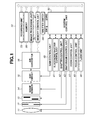
- Fig. 1 is a block diagram illustrating a configuration of an imaging apparatus according to a first exemplary embodiment.
- Fig. 7 is a table illustrating a method for adjusting weight coefficients.
- An imaging lens 11 is moved according to a control signal from a zoom control unit 44 or a control signal from a focus control unit 45.
- a diaphragm 12 is opened/closed according to a diaphragm control signal output from a diaphragm control unit 43 to control an amount of incident light.
- a shutter 13 is moved according to a shutter control signal transmitted from a shutter control unit 42.
- an image sensor 14 converts an optical image (object image) formed by the light flux led through an optical system including the imaging lens 11, the diaphragm 12, and the shutter 13 into an electric signal, and outputs the converted electric signal to an auto gain control (AGC) circuit 15.
- AGC auto gain control
- the AGC circuit 15 adjusts the gain of the image data transmitted from the image sensor 14 and outputs the adjusted image data to an analog/digital (A/D) converter 16.
- the image processing unit 20 performs image processing such as predetermined pixel correction processing, auto white balance (AWB) processing, color conversion processing, and specific color data extraction on the data from the A/D converter 16 or the data from the memory control unit 21.
- image processing such as predetermined pixel correction processing, auto white balance (AWB) processing, color conversion processing, and specific color data extraction on the data from the A/D converter 16 or the data from the memory control unit 21.
- the A/D converted image data has signal values of red (R), green (G), and blue (B) arranged in the Bayer array, and the image processing unit 20 performs pixel interpolation processing so that each pixel has the signal values of R, G, and B.
- the image processing unit 20 performs the AWB processing and the color conversion processing to convert the signal values of the R, G, and B into the signal values of brightness "Y" and color difference UV, and then outputs the converted signal values.
- the example of the signal of the input image data and that of the image data output from the image processing unit 20 are not limited thereto.
- the image processing unit 20 performs predetermined calculation processing using captured image data, and a system control unit 50 controls each unit based on the acquired calculation result. For example, auto focus processing of a through the lens (TTL) system is performed on the focus control unit 45.
- TTL through the lens
- AE auto exposure
- EF flash pre-emission
- the zoom control unit 44 controls the lens position of the imaging lens 11 to control zooming.
- the focus control unit 45 controls the lens position of the imaging lens 11 to control focusing.
- a shutter switch 60 includes shutter switches SW1 and SW2.
- the shutter switch SW1 is turned on while a shutter button (not illustrated) is being operated, and gives an instruction for starting operations of the AF processing and the AE processing.
- the shutter switch SW2 is turned on when the operation of the shutter button (not illustrated) has been completed.
- a user can instruct starting of controlling the flash unit 46 to flash, and of performing exposure processing for writing the signal read from the image sensor 14 into the memory 30 via the A/D converter 16 and the memory control unit 21, as image data. Further, is the user can instruct starting of operations of a series of processing including development processing using calculation performed by the image processing unit 20 and the memory control unit 21, and recording processing for reading the image data from the memory 30 and writing the image data into the recording unit 70.
- the recording unit 70 records an image signal transmitted from the image processing unit 20 in a recording medium.
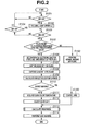
- step S101 when the shutter switch SW1 is pressed (YES in step S101), the processing proceeds to step S102.
- step S102 focusing and light metering processing is performed on the image data input from the A/D converter 16. The focusing and light-measuring processing performed in step S102 will be described in detail with reference to the flowchart illustrated in Fig. 3 .
- step S103 when the shutter switch SW2 is pressed (YES in step S103), the processing proceeds to step S105.
- step S104 when the shutter switch SW2 is not pressed (NO in step S103) and further the shutter switch SW1 is canceled (NO in step S104), the processing returns to step S101.
- step S150 when it is determined that the average brightness value is not less than the predetermined value (NO in step S105), then in step S150, even when it is determined that the average brightness value is the predetermined value or more in step S105, or when the flash mode is set to no-flash, the normal imaging is performed without the flash.
- step S106 based on the result of the light-metering in step S102, the image processing unit 20 or the system control unit 50 performs AE processing. More specifically, based on the brightness level calculated by the image processing unit 20, control values including the aperture size of the diaphragm, an electronic shutter speed, and the gain are calculated. The system control unit 50 transmits the control values determined according to the calculated control values to the gain control unit 40, the electronic shutter control unit 41, and the diaphragm control unit 43.
- control values including the aperture size of the diaphragm, the electronic shutter speed, and the gain are set to acquire the brightness level of the reflected light of the specific color at an appropriate level when the flash unit 46 is pre-flashed.
- the aperture size of the diaphragm and an amount of pre-flash by the flash are set appropriately not to cause a problem of gradation of the object. Further, to reduce effects of external light as much as possible, the electronic shutter speed is set high, and the gain is set low to reduce noise in the image signal.
- step S107 when the control values including the aperture size, the electronic shutter speed, and the gain are set for the diaphragm 12, the image sensor 14, and the AGC circuit 15, respectively, the object is captured without the flash unit 46 being flashed.
- the image signal is transmitted to the image processing unit 20 via the image sensor 14, the AGC circuit 15, and the A/D converter 16. After predetermined processing is performed on the image signal, the image signal is stored in the memory 30 as the no-flash image.
- step S108 the image is captured with the flash unit 46 being pre-flashed, and the captured image is transmitted to the image processing unit 20 via the image sensor 14, the AGC circuit 15, and the A/D converter 16.
- the image signal is stored in the memory 30 as a pre-flash image.
- the difference between environment light that is a light source of the no-flash image data, and the environment light and the flash light, which is a light source of the pre-flash image data, is calculated to acquire the image data from which the effect of the environment light is removed, and the data of the reflected-light brightness including only the flash light as the light source can be generated.
- step S112 white balance is controlled.
- the color temperature information about the flash unit 46 acquired in step S111 is read from the memory 30, and then the gain for each signal value of the R, G, and B of the image data is adjusted according to the color temperature (spectral characteristics) of the flash unit 46. More specifically, since the light source can be limited to the flash, white balance correction can be performed more accurately.
- step S160 when the flash unit 46 is set for a bounce state, since the light source is not limited to the flash light, the known AWB processing is performed to adjust the gain of each color of the R, G, and B.
- step S113 based on the gain-adjusted image data, predetermined calculation is performed to calculate a target value for the amount of the flash.
- a flash control signal based on the calculated target value for the amount of the flash is set for the flash unit 46. The calculation will be described in detail with reference to the flowchart illustrated in Fig. 4 below.
- step S114 based on an amount of main flash set by the flash unit 46, the flash is emitted to perform main imaging of the object.
- Fig. 3 is a flowchart illustrating details of focusing and light-metering processing performed in step S102 illustrated in Fig. 2 .
- step S201 a charge signal is read from the image sensor 14, and converted into digital data via the A/D converter 16, and then the digital data is input to the image processing unit 20.
- step S202 the image processing unit 20 determines the color temperature of the light source based on the input image data, and then a predetermined gain is applied for each color of each pixel (AWB processing).
- step S203 the image processing unit 20 performs the AF processing of a known contrast method using the input image data.
- step S204 predetermined processing is performed on the above-described image data to calculate a target value of an amount of exposure. Based on the calculated target value for the amount of the exposure, adjustment values of the diaphragm, the shutter speed, and the gain are determined. The calculation will be described in detail with reference to the flowchart illustrated in Fig. 4 .
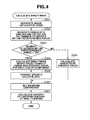
- Fig. 4 is a flowchart illustrating details of the calculation of the brightness performed in step S113 illustrated in Fig. 2 and in step S204 illustrated in Fig. 3 .
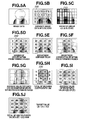
- Figs. 5A to 5J are image diagrams of respective steps illustrated in Fig. 4 .
- step S301 the image data is input in step S112 illustrated in Fig. 2 and in step S203 illustrated in Fig. 3 , and then separated into measurement blocks having a predetermined area by the image processing unit 20.
- Fig. 5A illustrates an example of the image data in which an image of a person is captured within a linearity range (within the dynamic range) of the image sensor 14 and its background is white out with signal values in a range outside the dynamic range.
- Fig. 5B is image data acquired by separating the image data illustrated in Fig 5A into the measurement blocks 200 of 4 ⁇ 4.
- step S302 the image data is separated into pixel groups, each of which is formed of a plurality of pixels including a plurality of color components in the measurement block, and then the number of groups (ratio) is calculated, all of whose pixel outputs are included within the range of linearity of the image sensor 14.
- Fig. 5C is an example where the block of (3, 4) is separated into 40 groups.
- Fig. 5D is acquired by calculating the number of the groups within the predetermined range for each block. As illustrated in the block of (0, 0), when the background is white out, the number of groups within the predetermined range is "0".
- step S303 it is determined whether a predetermined number of groups or more are included within the predetermined range.
- Fig. 5D displays, when a predetermined number is defined as 20 and when it is determined that the predetermined number of blocks or more are included, the blocks as blocks 220 within the predetermined range.
- step S304 the average value of the brightness of entire pixels within the block, which is the average value of overall brightness, is calculated in block units separated in the step S301.
- Fig. 5E illustrates the average value of the brightness calculated for each block.
- step S305 the average value of the brightness acquired using only the pixel groups, whose pixel output is each included within the predetermined range, and the average value of each color component are calculated for each block.
- Figs. 5F and 5G illustrate the average value of the brightness acquired using only the pixel group included within the predetermined range in the block 220 within the predetermined range and the average value of the color component for each color component.
- step S306 it is determined whether the average value of each color component within the predetermined range acquired in step S305 is included within a predetermined region in a color space indicating the specific color, and then the included block is determined to be a specific block.
- step S307 depending on a determination result of the specific color block and the number of groups within the predetermined range, the weighting coefficient for each block is adjusted.
- the adjustment of the weighting coefficient will be described in detail with reference to Fig. 7 .
- Fig. 5H indicates as a specific color block 230 the result when a skin color is extracted as the specific color, and then indicates the weighting coefficient according to the specific color.
- step S308 by adding and averaging the weighting coefficient calculated in step S306 and the average value of the brightness for each block detected in step S304 or step S306, the amount of the exposure for capturing the specific color with optimum exposure and the target value for the amount of the main flash are calculated.
- Fig. 5I indicates the average value of the brightness for each block detected in step S304 or step S306.
- the blocks 220 within the predetermined range have the average values of the brightness within the predetermined range indicated in Fig. 5F
- blocks other than the blocks within the predetermined range have the average values of the brightness indicated in Fig. 5E as the average value of the brightness.
- Fig. 5J indicates the calculation of the target value of 19.8 by performing division processing (adding and averaging processing) for dividing a total "5,650" of values, which is acquired by multiplying the average value of the brightness indicated in Fig 5I by the weighting coefficient indicated in Fig. 5H , by a total "285" of the weighting coefficient.
- Fig. 6 is a simplified graph illustrating a color difference plane with a vertical axis R/G and a horizontal axis B/G.
- the color temperature of the light source in an imaging environment is determined to control the AWB.
- a known technique is used for estimating the color temperature of the light source based on brightness information and color information acquired from the image in a screen, and adjusting the gains of the R, G, and B, so that the pixel outputs of the respective R, G, and B are at the same level when a white object is captured.
Landscapes
- Engineering & Computer Science (AREA)
- Multimedia (AREA)
- Signal Processing (AREA)
- Color Television Image Signal Generators (AREA)
- Studio Devices (AREA)
- Exposure Control For Cameras (AREA)
- Stroboscope Apparatuses (AREA)
Applications Claiming Priority (1)
| Application Number | Priority Date | Filing Date | Title |
|---|---|---|---|
| JP2011155908A JP5885416B2 (ja) | 2011-07-14 | 2011-07-14 | 撮像装置及び撮像装置の制御方法 |
Publications (2)
| Publication Number | Publication Date |
|---|---|
| EP2547092A2 true EP2547092A2 (de) | 2013-01-16 |
| EP2547092A3 EP2547092A3 (de) | 2016-12-21 |
Family
ID=46679095
Family Applications (1)
| Application Number | Title | Priority Date | Filing Date |
|---|---|---|---|
| EP12175940.1A Withdrawn EP2547092A3 (de) | 2011-07-14 | 2012-07-11 | Abbildungsvorrichtung zur Belichtungssteuerung, einschließlich Blitzlichtemengensteuerung der Blitzvorrichtung und Steuerverfahren dafür |
Country Status (4)
| Country | Link |
|---|---|
| US (1) | US9131197B2 (de) |
| EP (1) | EP2547092A3 (de) |
| JP (1) | JP5885416B2 (de) |
| CN (1) | CN102883107B (de) |
Families Citing this family (22)
| Publication number | Priority date | Publication date | Assignee | Title |
|---|---|---|---|---|
| US8717454B2 (en) * | 2009-12-24 | 2014-05-06 | Samsung Electronics Co., Ltd. | Image pickup apparatus and image pickup method for adjusting white balance to account for flash and external light sources |
| US20130176457A1 (en) * | 2012-01-09 | 2013-07-11 | Sawada Yasuhiro | Auto processing images having arbitrary regions of interest |
| US9411212B2 (en) * | 2013-01-25 | 2016-08-09 | Canon Kabushiki Kaisha | Illumination apparatus which is arrangeable so as to surround an image capturing lens |
| JP6351214B2 (ja) * | 2013-06-19 | 2018-07-04 | キヤノン株式会社 | 撮像装置、その制御方法、および制御プログラム |
| JP5947263B2 (ja) * | 2013-08-27 | 2016-07-06 | Necプラットフォームズ株式会社 | アンテナおよび無線通信装置 |
| JP6255931B2 (ja) * | 2013-11-19 | 2018-01-10 | リコーイメージング株式会社 | 照明装置、撮像装置、照明方法および反射領域判定装置 |
| US10154202B2 (en) * | 2014-10-15 | 2018-12-11 | Samsung Electronics Co., Ltd. | Apparatus for illuminating a scene and control method thereof |
| CN104967776B (zh) * | 2015-06-11 | 2018-03-27 | 广东欧珀移动通信有限公司 | 一种拍照设置方法及用户终端 |
| US10032252B2 (en) * | 2015-10-30 | 2018-07-24 | Canon Kabushiki Kaisha | Image processing apparatus, image capturing apparatus, image processing method, and non-transitory computer readable storage medium |
| TWI588587B (zh) | 2016-03-21 | 2017-06-21 | 鈺立微電子股份有限公司 | 影像擷取裝置及其操作方法 |
| JP6727920B2 (ja) * | 2016-05-17 | 2020-07-22 | キヤノン株式会社 | 撮像装置及び制御方法 |
| CN106791472B (zh) * | 2016-12-29 | 2019-07-30 | 努比亚技术有限公司 | 一种曝光方法及终端 |
| CN106952244B (zh) * | 2017-03-28 | 2020-05-05 | 中航视嘉(北京)技术有限公司 | 一种图像亮度的自动调整方法及装置 |
| JP6910837B2 (ja) * | 2017-04-14 | 2021-07-28 | キヤノン株式会社 | 撮像装置、撮像素子とその制御方法及びプログラム |
| US10154256B1 (en) * | 2017-06-13 | 2018-12-11 | Qualcomm Incorporated | Flash color calibration |
| CN107302663B (zh) * | 2017-07-31 | 2020-07-14 | 珠海大横琴科技发展有限公司 | 一种图像亮度调整方法、终端及计算机可读存储介质 |
| CN108810509B (zh) * | 2018-07-06 | 2020-08-11 | 北京中安未来科技有限公司 | 一种图像色彩校正方法及装置 |
| CN111372007B (zh) * | 2020-03-03 | 2021-11-12 | 荣耀终端有限公司 | 环境光照度的检测方法、装置和电子设备 |
| CN112702551A (zh) * | 2020-12-21 | 2021-04-23 | 上海眼控科技股份有限公司 | 一种闪电场视频录制方法、装置、设备及介质 |
| CN113099191B (zh) * | 2021-03-22 | 2023-04-07 | 浙江大华技术股份有限公司 | 一种图像处理方法及装置 |
| KR20220152019A (ko) * | 2021-05-07 | 2022-11-15 | 에스케이하이닉스 주식회사 | 이미지 센싱 장치 및 그 동작 방법 |
| JP2025002837A (ja) * | 2023-06-23 | 2025-01-09 | パナソニックIpマネジメント株式会社 | 撮像装置 |
Citations (2)
| Publication number | Priority date | Publication date | Assignee | Title |
|---|---|---|---|---|
| JPH0541830A (ja) | 1991-08-06 | 1993-02-19 | Minolta Camera Co Ltd | 人物適応露出制御装置 |
| JP2005065186A (ja) | 2003-08-20 | 2005-03-10 | Sony Corp | 撮像装置 |
Family Cites Families (9)
| Publication number | Priority date | Publication date | Assignee | Title |
|---|---|---|---|---|
| JPH11275454A (ja) * | 1998-03-23 | 1999-10-08 | Ricoh Co Ltd | デジタルビデオカメラ |
| JP4277406B2 (ja) * | 2000-01-26 | 2009-06-10 | 株式会社ニコン | 画像記録装置 |
| JP4636739B2 (ja) | 2001-06-29 | 2011-02-23 | キヤノン株式会社 | 撮像装置、撮像装置の制御方法、プログラム、及びコンピュータ読み取り可能な記憶媒体 |
| KR100816943B1 (ko) | 2003-08-26 | 2008-03-25 | 가시오게산키 가부시키가이샤 | 이미지 촬상장치 및 화이트 밸런스 제어방법 |
| JP4118864B2 (ja) | 2004-11-05 | 2008-07-16 | 三菱電機株式会社 | 撮像装置 |
| JP4115467B2 (ja) | 2005-06-01 | 2008-07-09 | 富士フイルム株式会社 | 撮影装置 |
| US8107762B2 (en) * | 2006-03-17 | 2012-01-31 | Qualcomm Incorporated | Systems, methods, and apparatus for exposure control |
| JP5169318B2 (ja) | 2007-09-18 | 2013-03-27 | 株式会社リコー | 撮像装置、撮像方法 |
| JP2010268134A (ja) * | 2009-05-13 | 2010-11-25 | Nikon Corp | 撮像装置 |
-
2011
- 2011-07-14 JP JP2011155908A patent/JP5885416B2/ja not_active Expired - Fee Related
-
2012
- 2012-07-10 US US13/545,767 patent/US9131197B2/en not_active Expired - Fee Related
- 2012-07-11 EP EP12175940.1A patent/EP2547092A3/de not_active Withdrawn
- 2012-07-13 CN CN201210244126.4A patent/CN102883107B/zh not_active Expired - Fee Related
Patent Citations (2)
| Publication number | Priority date | Publication date | Assignee | Title |
|---|---|---|---|---|
| JPH0541830A (ja) | 1991-08-06 | 1993-02-19 | Minolta Camera Co Ltd | 人物適応露出制御装置 |
| JP2005065186A (ja) | 2003-08-20 | 2005-03-10 | Sony Corp | 撮像装置 |
Also Published As
| Publication number | Publication date |
|---|---|
| US20130016249A1 (en) | 2013-01-17 |
| EP2547092A3 (de) | 2016-12-21 |
| JP2013021658A (ja) | 2013-01-31 |
| CN102883107A (zh) | 2013-01-16 |
| JP5885416B2 (ja) | 2016-03-15 |
| US9131197B2 (en) | 2015-09-08 |
| CN102883107B (zh) | 2016-01-06 |
Similar Documents
| Publication | Publication Date | Title |
|---|---|---|
| US9131197B2 (en) | Imaging apparatus capable of controlling exposure including flash amount control of flash apparatus, and control method thereof | |
| KR101900097B1 (ko) | 이미지 캡처 방법 및 이미지 캡처 장치 | |
| US8150252B2 (en) | Imaging apparatus and imaging apparatus control method | |
| US9137450B2 (en) | Image sensing apparatus, exposure control method and recording medium | |
| US9438815B2 (en) | Control device, control method, and control system with multiple dynamic ranges | |
| JP5597243B2 (ja) | 撮像装置 | |
| KR20150019710A (ko) | 촬영 장치 및 이의 제어 방법 | |
| KR20090098197A (ko) | 플래시 발광량 조절가능한 디지털 촬영 장치, 이의 제어방법 및 상기 방법을 실행하기 위한 프로그램을 기록한기록매체 | |
| US9888184B2 (en) | Light emission control device, control method therefor, storage medium storing control program therefor, and image pickup apparatus with light emission control device | |
| US8559809B2 (en) | Image shooting device | |
| US8593539B2 (en) | Image processing apparatus and image processing method for performance white balance processing | |
| EP2161938B1 (de) | Bildgebungsvorrichtung, Bildgebungsverfahren und computerlesbares Aufzeichnungsmedium mit darauf gespeicherten Programmen zur Ausführung des Bildgebungsverfahrens | |
| JP5791765B2 (ja) | 撮像装置及びその制御方法 | |
| JP2012163679A (ja) | 撮像装置、ストロボ制御方法およびストロボ制御プログラム | |
| US20170353660A1 (en) | Image capturing device and control method capable of adjusting exposure timing based on detected light quantity change characteristic | |
| JP5228318B2 (ja) | カメラおよび発光量演算プログラム | |
| US11637966B2 (en) | Imaging device and diaphragm mechanism control method | |
| KR101589493B1 (ko) | 플래시를 이용한 화이트 밸런스 조정 방법 및 장치, 이를 이용한 디지털 촬영 장치 | |
| US8149291B2 (en) | Image capture apparatus, control method thereof, program, and storage medium | |
| JP5791454B2 (ja) | 撮像装置、及びその制御方法 | |
| US20190045103A1 (en) | Image pickup apparatus capable of sufficiently ensuring accuracy of light emission and method of controlling same | |
| US20250039534A1 (en) | Imaging method, imaging apparatus, and program | |
| JP2014127770A (ja) | 撮像装置 | |
| KR20100047661A (ko) | 디지털 카메라의 노출 제어 장치 및 그 방법 | |
| JP2016019022A (ja) | 撮像装置、撮像装置の制御方法及びプログラム |
Legal Events
| Date | Code | Title | Description |
|---|---|---|---|
| PUAI | Public reference made under article 153(3) epc to a published international application that has entered the european phase |
Free format text: ORIGINAL CODE: 0009012 |
|
| AK | Designated contracting states |
Kind code of ref document: A2 Designated state(s): AL AT BE BG CH CY CZ DE DK EE ES FI FR GB GR HR HU IE IS IT LI LT LU LV MC MK MT NL NO PL PT RO RS SE SI SK SM TR |
|
| AX | Request for extension of the european patent |
Extension state: BA ME |
|
| PUAL | Search report despatched |
Free format text: ORIGINAL CODE: 0009013 |
|
| AK | Designated contracting states |
Kind code of ref document: A3 Designated state(s): AL AT BE BG CH CY CZ DE DK EE ES FI FR GB GR HR HU IE IS IT LI LT LU LV MC MK MT NL NO PL PT RO RS SE SI SK SM TR |
|
| AX | Request for extension of the european patent |
Extension state: BA ME |
|
| RIC1 | Information provided on ipc code assigned before grant |
Ipc: H04N 5/235 20060101AFI20161117BHEP Ipc: H04N 9/73 20060101ALI20161117BHEP |
|
| 17P | Request for examination filed |
Effective date: 20170621 |
|
| RBV | Designated contracting states (corrected) |
Designated state(s): AL AT BE BG CH CY CZ DE DK EE ES FI FR GB GR HR HU IE IS IT LI LT LU LV MC MK MT NL NO PL PT RO RS SE SI SK SM TR |
|
| GRAP | Despatch of communication of intention to grant a patent |
Free format text: ORIGINAL CODE: EPIDOSNIGR1 |
|
| INTG | Intention to grant announced |
Effective date: 20190618 |
|
| STAA | Information on the status of an ep patent application or granted ep patent |
Free format text: STATUS: THE APPLICATION HAS BEEN WITHDRAWN |
|
| 18W | Application withdrawn |
Effective date: 20191016 |