EP2546629A2 - Appareil et procédés pour l'acquisition d'analytes dans un échantillon de fluide biologique séché - Google Patents
Appareil et procédés pour l'acquisition d'analytes dans un échantillon de fluide biologique séché Download PDFInfo
- Publication number
- EP2546629A2 EP2546629A2 EP12175731A EP12175731A EP2546629A2 EP 2546629 A2 EP2546629 A2 EP 2546629A2 EP 12175731 A EP12175731 A EP 12175731A EP 12175731 A EP12175731 A EP 12175731A EP 2546629 A2 EP2546629 A2 EP 2546629A2
- Authority
- EP
- European Patent Office
- Prior art keywords
- substrate
- tube
- analytes
- sorbent bed
- section
- Prior art date
- Legal status (The legal status is an assumption and is not a legal conclusion. Google has not performed a legal analysis and makes no representation as to the accuracy of the status listed.)
- Withdrawn
Links
- 239000013060 biological fluid Substances 0.000 title claims abstract description 74
- 238000000034 method Methods 0.000 title claims description 47
- 239000000758 substrate Substances 0.000 claims abstract description 132
- 239000002594 sorbent Substances 0.000 claims abstract description 110
- 239000012156 elution solvent Substances 0.000 claims abstract description 32
- 239000002904 solvent Substances 0.000 claims abstract description 24
- 230000003750 conditioning effect Effects 0.000 claims abstract description 20
- 230000000717 retained effect Effects 0.000 claims abstract description 18
- 239000000203 mixture Substances 0.000 claims description 33
- 238000004458 analytical method Methods 0.000 claims description 21
- VYPSYNLAJGMNEJ-UHFFFAOYSA-N Silicium dioxide Chemical compound O=[Si]=O VYPSYNLAJGMNEJ-UHFFFAOYSA-N 0.000 claims description 11
- 238000002414 normal-phase solid-phase extraction Methods 0.000 claims description 11
- 239000003365 glass fiber Substances 0.000 claims description 10
- 229910044991 metal oxide Inorganic materials 0.000 claims description 10
- 150000004706 metal oxides Chemical class 0.000 claims description 10
- 229910052752 metalloid Inorganic materials 0.000 claims description 10
- 150000002738 metalloids Chemical class 0.000 claims description 10
- 229920000620 organic polymer Polymers 0.000 claims description 10
- -1 polypropylene Polymers 0.000 claims description 10
- 239000012530 fluid Substances 0.000 claims description 9
- 239000004952 Polyamide Substances 0.000 claims description 6
- 229920002678 cellulose Polymers 0.000 claims description 6
- 239000001913 cellulose Substances 0.000 claims description 6
- 238000004587 chromatography analysis Methods 0.000 claims description 6
- 229920001577 copolymer Polymers 0.000 claims description 6
- 229920002647 polyamide Polymers 0.000 claims description 6
- 239000000377 silicon dioxide Substances 0.000 claims description 5
- 238000012360 testing method Methods 0.000 claims description 5
- 238000005481 NMR spectroscopy Methods 0.000 claims description 4
- 238000005119 centrifugation Methods 0.000 claims description 4
- 239000002131 composite material Substances 0.000 claims description 4
- 230000002068 genetic effect Effects 0.000 claims description 4
- 238000005342 ion exchange Methods 0.000 claims description 4
- 230000006920 protein precipitation Effects 0.000 claims description 4
- 239000000020 Nitrocellulose Substances 0.000 claims description 3
- 239000004695 Polyether sulfone Substances 0.000 claims description 3
- 239000004698 Polyethylene Substances 0.000 claims description 3
- 239000004743 Polypropylene Substances 0.000 claims description 3
- 230000015572 biosynthetic process Effects 0.000 claims description 3
- 238000001035 drying Methods 0.000 claims description 3
- 238000003384 imaging method Methods 0.000 claims description 3
- 238000004949 mass spectrometry Methods 0.000 claims description 3
- 229920001220 nitrocellulos Polymers 0.000 claims description 3
- 229920000058 polyacrylate Polymers 0.000 claims description 3
- 229920006393 polyether sulfone Polymers 0.000 claims description 3
- 229920000573 polyethylene Polymers 0.000 claims description 3
- 229920000098 polyolefin Polymers 0.000 claims description 3
- 229920001155 polypropylene Polymers 0.000 claims description 3
- QQONPFPTGQHPMA-UHFFFAOYSA-N propylene Natural products CC=C QQONPFPTGQHPMA-UHFFFAOYSA-N 0.000 claims description 3
- 125000004805 propylene group Chemical group [H]C([H])([H])C([H])([*:1])C([H])([H])[*:2] 0.000 claims description 3
- 238000002798 spectrophotometry method Methods 0.000 claims description 3
- 239000000523 sample Substances 0.000 description 67
- 239000007788 liquid Substances 0.000 description 28
- 239000000463 material Substances 0.000 description 21
- 239000008280 blood Substances 0.000 description 16
- 210000004369 blood Anatomy 0.000 description 16
- OKKJLVBELUTLKV-UHFFFAOYSA-N Methanol Chemical compound OC OKKJLVBELUTLKV-UHFFFAOYSA-N 0.000 description 12
- 239000011159 matrix material Substances 0.000 description 12
- 239000002245 particle Substances 0.000 description 9
- 239000012071 phase Substances 0.000 description 9
- 238000012545 processing Methods 0.000 description 8
- 238000004080 punching Methods 0.000 description 8
- WEVYAHXRMPXWCK-UHFFFAOYSA-N Acetonitrile Chemical compound CC#N WEVYAHXRMPXWCK-UHFFFAOYSA-N 0.000 description 6
- YMWUJEATGCHHMB-UHFFFAOYSA-N Dichloromethane Chemical compound ClCCl YMWUJEATGCHHMB-UHFFFAOYSA-N 0.000 description 6
- 239000007791 liquid phase Substances 0.000 description 6
- RTZKZFJDLAIYFH-UHFFFAOYSA-N Diethyl ether Chemical compound CCOCC RTZKZFJDLAIYFH-UHFFFAOYSA-N 0.000 description 5
- 238000010828 elution Methods 0.000 description 4
- 239000012535 impurity Substances 0.000 description 4
- 102000004169 proteins and genes Human genes 0.000 description 4
- 108090000623 proteins and genes Proteins 0.000 description 4
- 239000000243 solution Substances 0.000 description 4
- XLYOFNOQVPJJNP-UHFFFAOYSA-N water Substances O XLYOFNOQVPJJNP-UHFFFAOYSA-N 0.000 description 4
- QTBSBXVTEAMEQO-UHFFFAOYSA-N Acetic acid Chemical compound CC(O)=O QTBSBXVTEAMEQO-UHFFFAOYSA-N 0.000 description 3
- CSCPPACGZOOCGX-UHFFFAOYSA-N Acetone Chemical compound CC(C)=O CSCPPACGZOOCGX-UHFFFAOYSA-N 0.000 description 3
- 102000053602 DNA Human genes 0.000 description 3
- 108020004414 DNA Proteins 0.000 description 3
- LFQSCWFLJHTTHZ-UHFFFAOYSA-N Ethanol Chemical compound CCO LFQSCWFLJHTTHZ-UHFFFAOYSA-N 0.000 description 3
- XEKOWRVHYACXOJ-UHFFFAOYSA-N Ethyl acetate Chemical compound CCOC(C)=O XEKOWRVHYACXOJ-UHFFFAOYSA-N 0.000 description 3
- 229910000831 Steel Inorganic materials 0.000 description 3
- 239000000872 buffer Substances 0.000 description 3
- 238000004891 communication Methods 0.000 description 3
- 150000001875 compounds Chemical class 0.000 description 3
- 238000004817 gas chromatography Methods 0.000 description 3
- 238000003780 insertion Methods 0.000 description 3
- 230000037431 insertion Effects 0.000 description 3
- 238000004811 liquid chromatography Methods 0.000 description 3
- VLKZOEOYAKHREP-UHFFFAOYSA-N n-Hexane Chemical compound CCCCCC VLKZOEOYAKHREP-UHFFFAOYSA-N 0.000 description 3
- 239000004033 plastic Substances 0.000 description 3
- 229920003023 plastic Polymers 0.000 description 3
- 229920002477 rna polymer Polymers 0.000 description 3
- 239000007787 solid Substances 0.000 description 3
- 239000010959 steel Substances 0.000 description 3
- 230000007704 transition Effects 0.000 description 3
- HEDRZPFGACZZDS-UHFFFAOYSA-N Chloroform Chemical compound ClC(Cl)Cl HEDRZPFGACZZDS-UHFFFAOYSA-N 0.000 description 2
- KFZMGEQAYNKOFK-UHFFFAOYSA-N Isopropanol Chemical compound CC(C)O KFZMGEQAYNKOFK-UHFFFAOYSA-N 0.000 description 2
- BZLVMXJERCGZMT-UHFFFAOYSA-N Methyl tert-butyl ether Chemical compound COC(C)(C)C BZLVMXJERCGZMT-UHFFFAOYSA-N 0.000 description 2
- WYURNTSHIVDZCO-UHFFFAOYSA-N Tetrahydrofuran Chemical compound C1CCOC1 WYURNTSHIVDZCO-UHFFFAOYSA-N 0.000 description 2
- GWEVSGVZZGPLCZ-UHFFFAOYSA-N Titan oxide Chemical compound O=[Ti]=O GWEVSGVZZGPLCZ-UHFFFAOYSA-N 0.000 description 2
- XSQUKJJJFZCRTK-UHFFFAOYSA-N Urea Chemical compound NC(N)=O XSQUKJJJFZCRTK-UHFFFAOYSA-N 0.000 description 2
- MCMNRKCIXSYSNV-UHFFFAOYSA-N Zirconium dioxide Chemical compound O=[Zr]=O MCMNRKCIXSYSNV-UHFFFAOYSA-N 0.000 description 2
- 125000000217 alkyl group Chemical group 0.000 description 2
- 230000004323 axial length Effects 0.000 description 2
- 238000004140 cleaning Methods 0.000 description 2
- 230000008878 coupling Effects 0.000 description 2
- 238000010168 coupling process Methods 0.000 description 2
- 238000005859 coupling reaction Methods 0.000 description 2
- 238000012864 cross contamination Methods 0.000 description 2
- 238000003795 desorption Methods 0.000 description 2
- 238000011161 development Methods 0.000 description 2
- 230000018109 developmental process Effects 0.000 description 2
- 150000002009 diols Chemical class 0.000 description 2
- 238000009826 distribution Methods 0.000 description 2
- 238000000605 extraction Methods 0.000 description 2
- 238000002290 gas chromatography-mass spectrometry Methods 0.000 description 2
- 229920001519 homopolymer Polymers 0.000 description 2
- 238000007834 ligase chain reaction Methods 0.000 description 2
- 238000004895 liquid chromatography mass spectrometry Methods 0.000 description 2
- 230000014759 maintenance of location Effects 0.000 description 2
- BDAGIHXWWSANSR-UHFFFAOYSA-N methanoic acid Natural products OC=O BDAGIHXWWSANSR-UHFFFAOYSA-N 0.000 description 2
- 230000003287 optical effect Effects 0.000 description 2
- 229920000642 polymer Polymers 0.000 description 2
- 229920002959 polymer blend Polymers 0.000 description 2
- 238000003752 polymerase chain reaction Methods 0.000 description 2
- 239000011148 porous material Substances 0.000 description 2
- 125000002924 primary amino group Chemical group [H]N([H])* 0.000 description 2
- 238000012340 reverse transcriptase PCR Methods 0.000 description 2
- 238000004611 spectroscopical analysis Methods 0.000 description 2
- VZGDMQKNWNREIO-UHFFFAOYSA-N tetrachloromethane Chemical compound ClC(Cl)(Cl)Cl VZGDMQKNWNREIO-UHFFFAOYSA-N 0.000 description 2
- OSWFIVFLDKOXQC-UHFFFAOYSA-N 4-(3-methoxyphenyl)aniline Chemical compound COC1=CC=CC(C=2C=CC(N)=CC=2)=C1 OSWFIVFLDKOXQC-UHFFFAOYSA-N 0.000 description 1
- LSNNMFCWUKXFEE-UHFFFAOYSA-M Bisulfite Chemical compound OS([O-])=O LSNNMFCWUKXFEE-UHFFFAOYSA-M 0.000 description 1
- 206010006223 Breast discharge Diseases 0.000 description 1
- 239000004593 Epoxy Substances 0.000 description 1
- JOYRKODLDBILNP-UHFFFAOYSA-N Ethyl urethane Chemical compound CCOC(N)=O JOYRKODLDBILNP-UHFFFAOYSA-N 0.000 description 1
- NHTMVDHEPJAVLT-UHFFFAOYSA-N Isooctane Chemical compound CC(C)CC(C)(C)C NHTMVDHEPJAVLT-UHFFFAOYSA-N 0.000 description 1
- 239000004677 Nylon Substances 0.000 description 1
- 229910019142 PO4 Inorganic materials 0.000 description 1
- 206010036790 Productive cough Diseases 0.000 description 1
- QAOWNCQODCNURD-UHFFFAOYSA-L Sulfate Chemical compound [O-]S([O-])(=O)=O QAOWNCQODCNURD-UHFFFAOYSA-L 0.000 description 1
- 229910021536 Zeolite Inorganic materials 0.000 description 1
- 239000002250 absorbent Substances 0.000 description 1
- 230000002745 absorbent Effects 0.000 description 1
- 230000004913 activation Effects 0.000 description 1
- 239000000654 additive Substances 0.000 description 1
- 238000007605 air drying Methods 0.000 description 1
- 125000003342 alkenyl group Chemical group 0.000 description 1
- 125000000304 alkynyl group Chemical group 0.000 description 1
- PNEYBMLMFCGWSK-UHFFFAOYSA-N aluminium oxide Inorganic materials [O-2].[O-2].[O-2].[Al+3].[Al+3] PNEYBMLMFCGWSK-UHFFFAOYSA-N 0.000 description 1
- 125000003368 amide group Chemical group 0.000 description 1
- 150000001408 amides Chemical class 0.000 description 1
- 239000012491 analyte Substances 0.000 description 1
- 238000012863 analytical testing Methods 0.000 description 1
- 239000012062 aqueous buffer Substances 0.000 description 1
- 125000002648 azanetriyl group Chemical group *N(*)* 0.000 description 1
- 239000012472 biological sample Substances 0.000 description 1
- 229920001222 biopolymer Polymers 0.000 description 1
- 239000004202 carbamide Substances 0.000 description 1
- 125000002915 carbonyl group Chemical group [*:2]C([*:1])=O 0.000 description 1
- 125000003178 carboxy group Chemical group [H]OC(*)=O 0.000 description 1
- 210000004027 cell Anatomy 0.000 description 1
- 239000003153 chemical reaction reagent Substances 0.000 description 1
- 239000012141 concentrate Substances 0.000 description 1
- 239000000470 constituent Substances 0.000 description 1
- 238000005520 cutting process Methods 0.000 description 1
- 238000010790 dilution Methods 0.000 description 1
- 239000012895 dilution Substances 0.000 description 1
- JVSWJIKNEAIKJW-UHFFFAOYSA-N dimethyl-hexane Natural products CCCCCC(C)C JVSWJIKNEAIKJW-UHFFFAOYSA-N 0.000 description 1
- HNPSIPDUKPIQMN-UHFFFAOYSA-N dioxosilane;oxo(oxoalumanyloxy)alumane Chemical compound O=[Si]=O.O=[Al]O[Al]=O HNPSIPDUKPIQMN-UHFFFAOYSA-N 0.000 description 1
- KZHJGOXRZJKJNY-UHFFFAOYSA-N dioxosilane;oxo(oxoalumanyloxy)alumane Chemical compound O=[Si]=O.O=[Si]=O.O=[Al]O[Al]=O.O=[Al]O[Al]=O.O=[Al]O[Al]=O KZHJGOXRZJKJNY-UHFFFAOYSA-N 0.000 description 1
- 238000006073 displacement reaction Methods 0.000 description 1
- 125000004119 disulfanediyl group Chemical group *SS* 0.000 description 1
- 239000003814 drug Substances 0.000 description 1
- 229940079593 drug Drugs 0.000 description 1
- 238000011067 equilibration Methods 0.000 description 1
- 239000000284 extract Substances 0.000 description 1
- 239000000835 fiber Substances 0.000 description 1
- 239000000945 filler Substances 0.000 description 1
- 235000019253 formic acid Nutrition 0.000 description 1
- 230000005484 gravity Effects 0.000 description 1
- 125000002795 guanidino group Chemical group C(N)(=N)N* 0.000 description 1
- 238000010438 heat treatment Methods 0.000 description 1
- 238000009396 hybridization Methods 0.000 description 1
- 125000001183 hydrocarbyl group Chemical group 0.000 description 1
- 125000004356 hydroxy functional group Chemical group O* 0.000 description 1
- 238000003859 hyphenated technique Methods 0.000 description 1
- 238000012606 in vitro cell culture Methods 0.000 description 1
- 238000001746 injection moulding Methods 0.000 description 1
- 150000002500 ions Chemical class 0.000 description 1
- 230000001788 irregular Effects 0.000 description 1
- 125000001261 isocyanato group Chemical group *N=C=O 0.000 description 1
- 238000002372 labelling Methods 0.000 description 1
- 150000002632 lipids Chemical class 0.000 description 1
- 210000002751 lymph Anatomy 0.000 description 1
- 239000006166 lysate Substances 0.000 description 1
- 238000004519 manufacturing process Methods 0.000 description 1
- 230000007246 mechanism Effects 0.000 description 1
- 230000028161 membrane depolarization Effects 0.000 description 1
- 125000002496 methyl group Chemical group [H]C([H])([H])* 0.000 description 1
- 125000001570 methylene group Chemical group [H]C([H])([*:1])[*:2] 0.000 description 1
- 230000000813 microbial effect Effects 0.000 description 1
- 238000000386 microscopy Methods 0.000 description 1
- 210000003097 mucus Anatomy 0.000 description 1
- 229910052863 mullite Inorganic materials 0.000 description 1
- 125000000449 nitro group Chemical group [O-][N+](*)=O 0.000 description 1
- 125000000018 nitroso group Chemical group N(=O)* 0.000 description 1
- 229920001778 nylon Polymers 0.000 description 1
- 239000003921 oil Substances 0.000 description 1
- 239000006174 pH buffer Substances 0.000 description 1
- 238000012856 packing Methods 0.000 description 1
- 239000000546 pharmaceutical excipient Substances 0.000 description 1
- NBIIXXVUZAFLBC-UHFFFAOYSA-K phosphate Chemical compound [O-]P([O-])([O-])=O NBIIXXVUZAFLBC-UHFFFAOYSA-K 0.000 description 1
- 239000010452 phosphate Substances 0.000 description 1
- 210000002381 plasma Anatomy 0.000 description 1
- 239000002244 precipitate Substances 0.000 description 1
- 238000002360 preparation method Methods 0.000 description 1
- 238000004237 preparative chromatography Methods 0.000 description 1
- 230000008569 process Effects 0.000 description 1
- 125000002572 propoxy group Chemical group [*]OC([H])([H])C(C([H])([H])[H])([H])[H] 0.000 description 1
- 238000012950 reanalysis Methods 0.000 description 1
- 230000009467 reduction Effects 0.000 description 1
- 150000003839 salts Chemical class 0.000 description 1
- 230000035945 sensitivity Effects 0.000 description 1
- 238000012163 sequencing technique Methods 0.000 description 1
- 210000002966 serum Anatomy 0.000 description 1
- FZHAPNGMFPVSLP-UHFFFAOYSA-N silanamine Chemical class [SiH3]N FZHAPNGMFPVSLP-UHFFFAOYSA-N 0.000 description 1
- 150000004756 silanes Chemical class 0.000 description 1
- 125000005372 silanol group Chemical class 0.000 description 1
- 239000002002 slurry Substances 0.000 description 1
- 150000003384 small molecules Chemical class 0.000 description 1
- 241000894007 species Species 0.000 description 1
- 210000003802 sputum Anatomy 0.000 description 1
- 208000024794 sputum Diseases 0.000 description 1
- 238000012414 sterilization procedure Methods 0.000 description 1
- 238000003860 storage Methods 0.000 description 1
- 239000000126 substance Substances 0.000 description 1
- 125000000446 sulfanediyl group Chemical group *S* 0.000 description 1
- 125000000475 sulfinyl group Chemical group [*:2]S([*:1])=O 0.000 description 1
- 125000005420 sulfonamido group Chemical group S(=O)(=O)(N*)* 0.000 description 1
- 239000004094 surface-active agent Substances 0.000 description 1
- 239000000725 suspension Substances 0.000 description 1
- YLQBMQCUIZJEEH-UHFFFAOYSA-N tetrahydrofuran Natural products C=1C=COC=1 YLQBMQCUIZJEEH-UHFFFAOYSA-N 0.000 description 1
- 210000001519 tissue Anatomy 0.000 description 1
- 238000012546 transfer Methods 0.000 description 1
- 238000005406 washing Methods 0.000 description 1
- 239000010457 zeolite Substances 0.000 description 1
Images


Classifications
-
- G—PHYSICS
- G01—MEASURING; TESTING
- G01N—INVESTIGATING OR ANALYSING MATERIALS BY DETERMINING THEIR CHEMICAL OR PHYSICAL PROPERTIES
- G01N1/00—Sampling; Preparing specimens for investigation
- G01N1/28—Preparing specimens for investigation including physical details of (bio-)chemical methods covered elsewhere, e.g. G01N33/50, C12Q
- G01N1/40—Concentrating samples
- G01N1/405—Concentrating samples by adsorption or absorption
-
- B—PERFORMING OPERATIONS; TRANSPORTING
- B01—PHYSICAL OR CHEMICAL PROCESSES OR APPARATUS IN GENERAL
- B01L—CHEMICAL OR PHYSICAL LABORATORY APPARATUS FOR GENERAL USE
- B01L3/00—Containers or dishes for laboratory use, e.g. laboratory glassware; Droppers
- B01L3/02—Burettes; Pipettes
- B01L3/0275—Interchangeable or disposable dispensing tips
-
- G—PHYSICS
- G01—MEASURING; TESTING
- G01N—INVESTIGATING OR ANALYSING MATERIALS BY DETERMINING THEIR CHEMICAL OR PHYSICAL PROPERTIES
- G01N1/00—Sampling; Preparing specimens for investigation
- G01N1/28—Preparing specimens for investigation including physical details of (bio-)chemical methods covered elsewhere, e.g. G01N33/50, C12Q
- G01N1/40—Concentrating samples
- G01N1/4055—Concentrating samples by solubility techniques
-
- B—PERFORMING OPERATIONS; TRANSPORTING
- B01—PHYSICAL OR CHEMICAL PROCESSES OR APPARATUS IN GENERAL
- B01L—CHEMICAL OR PHYSICAL LABORATORY APPARATUS FOR GENERAL USE
- B01L2300/00—Additional constructional details
- B01L2300/06—Auxiliary integrated devices, integrated components
- B01L2300/069—Absorbents; Gels to retain a fluid
-
- G—PHYSICS
- G01—MEASURING; TESTING
- G01N—INVESTIGATING OR ANALYSING MATERIALS BY DETERMINING THEIR CHEMICAL OR PHYSICAL PROPERTIES
- G01N1/00—Sampling; Preparing specimens for investigation
- G01N1/28—Preparing specimens for investigation including physical details of (bio-)chemical methods covered elsewhere, e.g. G01N33/50, C12Q
- G01N1/40—Concentrating samples
- G01N1/4055—Concentrating samples by solubility techniques
- G01N2001/4061—Solvent extraction
-
- Y—GENERAL TAGGING OF NEW TECHNOLOGICAL DEVELOPMENTS; GENERAL TAGGING OF CROSS-SECTIONAL TECHNOLOGIES SPANNING OVER SEVERAL SECTIONS OF THE IPC; TECHNICAL SUBJECTS COVERED BY FORMER USPC CROSS-REFERENCE ART COLLECTIONS [XRACs] AND DIGESTS
- Y10—TECHNICAL SUBJECTS COVERED BY FORMER USPC
- Y10T—TECHNICAL SUBJECTS COVERED BY FORMER US CLASSIFICATION
- Y10T436/00—Chemistry: analytical and immunological testing
- Y10T436/25—Chemistry: analytical and immunological testing including sample preparation
- Y10T436/25375—Liberation or purification of sample or separation of material from a sample [e.g., filtering, centrifuging, etc.]
- Y10T436/255—Liberation or purification of sample or separation of material from a sample [e.g., filtering, centrifuging, etc.] including use of a solid sorbent, semipermeable membrane, or liquid extraction
Definitions
- the present invention relates generally to dried biological fluid sample analysis and the formation and processing of dried biological fluid samples in preparation for subsequent analysis.
- Dried biological fluid sample analysis such as dried blood spot (DBS) analysis is becoming increasingly popular for pharmaceutical companies in clinical trials. Collection sites for clinical trials may sample blood spots (or other types of biological fluid spots) in the field, allow the spots to dry, and then ship the spots at a lower cost than liquid samples due to the non-biohazard status of dried blood spots and the less rigorous requirements for temperature control. Blood spotting is also becoming useful in preclinical work as analytical chemists are required to store samples for Incurred Sample Reanalysis (ISR) studies, and dried blood spots have proven to be an effective way to stabilize the analytes and the matrix.
- ISR Incurred Sample Reanalysis
- DBS samples are prepared by applying drops of blood, typically obtained from venipuncture of a human or animal, to an absorbent substrate (e.g., filter paper) of an appropriate composition.
- the blood saturates the substrate and is air dried for a period of time (e.g., several hours) sufficient to form an array of circular dried blood spots on the substrate.
- the spot-containing substrate may then be stored in a plastic container and transported as needed without needing to be frozen.
- the dried blood spots may thereafter be separated from the bulk substrate by punching the dried blood spots to create individual dried blood spot disks.
- Analytes such as pharmaceutical compounds, genetic materials, etc. (i.e., small molecules or high molecular weight molecules) may then be extracted from dried blood spots by any number of techniques and subjected to analytical testing. Other types of biological fluid samples may be dried and subsequently processed in an analogous manner.
- the processing of dried blood spots and other types of biological fluid spots has many problems.
- labs typically utilize a single punching device for multiple sample spotting procedures. Even with the use of cleaning and sterilization procedures, the repeated use of the same punching device can cause carryover and cross-contamination.
- the conventional punch device is typically constructed of steel so as to be hard or strong enough to punch through conventional spotting substrates. The steel punching device often must be employed with a hammer to achieve effective punching.
- steel is generally not considered to be readily disposable as compared to other types of materials such as various plastics. More generally, the requirement by conventional procedures of the use of a punching device is, in and of itself, laborious ad time-consuming.
- the present disclosure provides methods, processes, systems, apparatus, instruments, and/or devices, as described by way of example in implementations set forth below.
- a method for acquiring analytes from a dried biological fluid sample.
- a biological fluid sample is dispensed on a substrate disposed in a fixed position in a proximal section of a tube.
- the biological fluid sample is dried on the substrate to form a dried biological fluid sample.
- a conditioning solvent is flowed into a distal section of the tube adjoining the proximal section to condition a sorbent bed disposed in a fixed position in the distal section.
- An elution solvent is flowed through the substrate and the sorbent bed, wherein analytes are eluted from the dried biological fluid sample.
- the analytes passing through an opening of the distal section are collected.
- the eluted analytes are passed through the sorbent bed and to the opening, while retaining non-analytes on the sorbent bed.
- the elution solvent by which the analytes are eluted from the dried biological fluid sample is a first elution solvent, and the eluted analytes are retained on the sorbent bed.
- a second elution solvent is flowed through the substrate and the sorbent bed, wherein the analytes are eluted from the sorbent bed and pass through the opening.
- a wash solvent is flowed through the substrate and the sorbent bed to remove residual non-analytes from the tube.
- a method for acquiring analytes from a dried biological fluid sample.
- a biological fluid sample is dispensed on a substrate that is disposed in a fixed position in a proximal section of a tube.
- the biological fluid sample is dried on the substrate to form a dried biological fluid sample.
- a conditioning solvent is flowed into a distal section of the tube adjoining the proximal section to condition a sorbent bed disposed in a fixed position in the distal section.
- a first elution solvent is flowed through the substrate and the sorbent bed.
- Analytes are eluted from the dried biological fluid sample and retained on the sorbent bed.
- a second elution solvent is flowed through the substrate and the sorbent bed.
- the analytes are eluted from the sorbent bed and pass through the distal tube opening.
- the analytes passing through the distal tube opening are collected.
- the first elution solvent is flowed through a proximal tube opening of the proximal section, through the proximal section, through the distal section, and through a distal tube opening of the distal section.
- the second elution solvent is flowed through the proximal tube opening, the proximal section, the distal section and the distal tube opening.
- a wash solvent is flowed through the substrate and the sorbent bed to remove residual non-analytes from the tube.
- a method for acquiring analytes from a dried biological fluid sample.
- a biological fluid sample is dispensed on a substrate disposed in a fixed position in a proximal section of a tube.
- the biological fluid sample is dried on the substrate to form a dried biological fluid sample.
- a conditioning solvent is flowed into a distal section of the tube adjoining the proximal section to condition a sorbent bed disposed in a fixed position in the distal section.
- An elution solvent is flowed through the substrate and the sorbent bed.
- Analytes are eluted from the dried biological fluid sample and pass through the sorbent bed and an opening of the distal section, while non-analytes are retained on the sorbent bed. The analytes passing through the opening are collected.
- the elution solvent is flowed through a proximal tube opening of the proximal section, through the proximal section, through the distal section, and through a distal tube opening of the distal section.
- the substrate may be installed in the proximal section.
- the substrate is installed by inserting the substrate through an opening of the proximal section and fixing the position of the substrate in the proximal section.
- the position of the substrate may be fixed by bringing the substrate into frictional contact with an inner surface of the proximal section, bringing the substrate into contact with an inner shoulder of the proximal section, placing the substrate between two inner shoulders of the proximal section, bringing the substrate into contact with a ring disposed in the proximal section, placing the substrate between two rings disposed in the proximal section, bringing the substrate into contact with a frit disposed in the proximal section, or placing the substrate between two frits disposed in the proximal section.
- the collected analytes may be subjected to an analytical procedure such as protein precipitation, fraction collection, centrifugation, spectrophotometry, imaging, nuclear magnetic resonance spectrometry, solid phase extraction, chromatography, mass spectrometry, genetic testing, and a combination of two or more of the foregoing.
- an analytical procedure such as protein precipitation, fraction collection, centrifugation, spectrophotometry, imaging, nuclear magnetic resonance spectrometry, solid phase extraction, chromatography, mass spectrometry, genetic testing, and a combination of two or more of the foregoing.
- the biological fluid sample may be a blood-based sample.
- an apparatus for acquiring analytes from a dried biological fluid sample includes a tube, a substrate, and a sorbent bed.
- the tube includes a proximal section and a distal section adjoining the proximal section.
- the proximal section includes a proximal tube end circumscribing a proximal tube opening.
- the distal section includes a distal tube end circumscribing a distal tube opening of lesser inside diameter than the proximal tube opening.
- the substrate is disposed in a fixed position in the proximal section between the proximal tube end and the distal section, and spans a cross-sectional area of the proximal section.
- the substrate has a composition configured for dried biological fluid sample formation.
- the sorbent bed is disposed in a fixed position in the distal tube section between the proximal section and the distal tube end, and spans a cross-sectional area of the distal section.
- the sorbent bed has a composition configured for solid phase extraction.
- the apparatus establishes a fluid flow path from the proximal tube opening, through the proximal tube section including through the substrate, through the distal tube section including through the sorbent bed, and to the distal tube opening.
- the tube may enclose a volume between the proximal tube end and the distal tube end, and the volume ranges from 100 to 5000 ⁇ L.
- the inside diameter of the proximal tube opening is greater than an outside diameter of the substrate
- the proximal section has an inside diameter that tapers from a maximum inside diameter at the proximal tube opening to a minimum inside diameter, and the minimum inside diameter is less than the outside diameter of the substrate.
- the inside diameter of the distal tube opening ranges from 1 to 6 mm.
- the composition of the tube is an organic polymer, an organic copolymer, or an organic polymer blend. In some implementations, the composition of the tube is a polyolefin, polypropylene, polyethylene, polyamide, polyacrylate, or a combination of two of more of the foregoing.
- the substrate is disposed in the proximal section according to one of the following configurations: the substrate is in frictional contact with an inner surface of the proximal section, the substrate is in contact with an inner shoulder of the proximal section, the substrate is interposed between two inner shoulders of the proximal section, the substrate is in contact with a ring disposed in the proximal section, the substrate is interposed between two rings disposed in the proximal section, the substrate is in contact with a frit disposed in the proximal section, or the substrate is interposed between two frits disposed in the proximal section.
- the substrate has an outside diameter ranging from 1 to 10 mm.
- the composition of the substrate is silica, a cellulosic filter paper, a glass fiber/cellulose composite, a cellulose-free glass fiber paper, a polyamide, propylene, nitrocellulose, polyethersulfone, or combinations of two or more of the foregoing.
- the sorbent bed is positioned at an axial distance from the distal tube opening, and the axial distance ranges from 1 to 5 mm.
- the sorbent bed has a mass ranging from 1 to 10 mg.
- the composition of the sorbent bed is an organic polymer, an organic copolymer, an organic polymer blend, a glass fiber cellulose, a metal oxide or metalloid oxide, an ion exchange modified metal oxide or metalloid oxide, a functionalized metal oxide or metalloid oxide, or combinations of two or more of the foregoing.
- the composition of the sorbent bed is configured for retaining analytes from a dried biological fluid sample. In other implementations, the composition of the sorbent bed is configured for retaining non-analytical components while passing analytes from a dried biological fluid sample. In other implementations, the composition of the sorbent bed is configured for retaining analytes from a dried biological fluid sample and for retaining non-analytical components.
- a kit for acquiring analytes from a dried biological fluid sample.
- the kit may include one or more tubes, one or more substrates, and one or more sorbent beds.
- the kit may also include one or more frits and/or one or more rings.
- the kit may also include tangible media providing, for example, instructions for assembling and/or utilizing an apparatus that includes a tube, a substrate, and a sorbent bed.
- Figure 1 is an elevation view of an example of an apparatus for extracting analytes from a dried biological fluid sample according to an implementation of the present teachings.
- Figure 2 is a cross-sectional view of a substrate of the apparatus illustrated in Figure 1 , according to an implementation in which the substrate is disposed on an inside shoulder (or rib) of the apparatus.
- Figure 3 is a cross-sectional view of the substrate of the apparatus illustrated in Figure 1 , according to another implementation in which the substrate is disposed on a frit or ring that is positioned in the apparatus.
- Figure 4 is an elevation view of the apparatus illustrated in Figure 1 after a conditioning medium has been added.
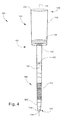
- Figure 5 is an elevation view of the apparatus illustrated in Figure 1 after an elution solvent has been added.
- liquid-phase material refers generally to liquid-phase materials and gas-phase materials, unless a liquid-phase material or a gas-phase material is specifically indicated.
- liquid-phase and “liquid,” and “gas-phase” and “gas,” are used interchangeably.
- a liquid-phase material or liquid may be any liquid, such as a solution, suspension, slurry, multi-phase mixture or the like, and may include gaseous components (e.g., bubbles) and/or solid components (e.g., particles).
- a gas-phase material or gas may be any gas or vapor, and may include liquid components (e.g., droplets) and/or solid components (e.g., particles).
- the term “dried fluid sample” or “dried fluid spot” refers generally to a material that was initially provided in the liquid phase and was thereafter dried, such as by air drying.
- biological fluid sample generally refers to a sample of biological fluid obtained from plant, animal, microbial material, in vitro cell culture constituents, as well as samples from the environment.
- biological fluid sample include blood, plasma, serum, lymph, sputum, stool, tears, mucus, hair, skin, buccal scrape, nipple discharge, etc., as well as a homogenate, lysate or extract prepared from a whole organism or a subset of its tissues, cells or componenets parts or a fraction or portion thereof.
- analyte refers generally to any sample molecule of interest-that is, a molecule on which an analysis is desired such as, for example, a chromatographic analysis.
- sample matrix refers to any combination of analytes and non-analytes.
- the combination of analytes and non-analytes may exist in a liquid phase and/or a gas phase.
- non-analytes or “non-analytical components” in this context refers to components of the sample matrix for which analysis is not of interest because such components do not have analytical value and/or impair (e.g., interfere with) the analysis of the desired analytes.
- non-analytes may include water, oils, or other media in which the desired analytes may be found, molecules not of interest, as well as solvents, buffers, reagents, and various solid particles such as excipients, precipitates, fillers, and impurities.
- the term “diameter” refers in a general sense to the characteristic dimension of any shape and therefore does not necessarily imply a circular shape.
- the characteristic dimension of a tube of circular cross-section may be considered a diameter
- the characteristic dimension of a tube of elliptical cross-section may be considered a major axis
- the characteristic dimension of a tube of polygonal cross-section may be considered the length (width) of a side or the distance between two inside corners.
- the term “diameter” encompasses all such types of characteristic dimensions.
- Figure 1 is an elevation view of an example of an apparatus 100 for extracting analytes from a dried biological fluid sample according to an implementation of the present teachings.
- the apparatus 100 generally includes a tube (or pipette, etc.) 104, a substrate 108, and a sorbent bed 112 (or plug, mass, or packing of sorbent material).
- the tube 104 is generally situated along a longitudinal axis 116.
- the tube 104 has a generally straight orientation along the longitudinal axis 116, while in other implementations the tube 104 may include one or more curved or angled sections.
- the tube 104 generally includes a hollow body 120 coaxial with the longitudinal axis 116.
- the hollow body 120 may include a single tube wall or two or more adjoined walls.
- the hollow body 120 defines an internal cross-sectional area which, from the perspective of Figure 1 , is orthogonal to the longitudinal axis 116.
- the cross-sectional area may be circular as in the illustrated example, or alternatively may be elliptical or polygonal.
- the tube 104 terminates at a distal tube end 124 and an axially opposite proximal tube end 128.
- the distal tube end 124 circumscribes a distal tube opening 132
- the proximal tube end 128 circumscribes a proximal tube opening 136.
- the inside diameter of the distal tube opening 132 is less than the inside diameter of the proximal tube opening 136.
- the tube 104 further includes a distal section (or pipette tip) 140 generally defined by a portion of the hollow body 120 that extends to (terminates at) the distal tube opening 132.
- the distal section 140 or a distal-most portion of the distal section 140, may include a tapered distal tube wall 142 such that the inside diameter of the distal section 140 (or at least a distal-most portion of the distal section 140) tapers in the axial direction generally toward the distal tube end 124, whereby the distal tube opening 132 is the minimum inside diameter of the distal section 140.
- Both the inside surface and the outside surface of the wall of the distal section 140 may be tapered (relative to the longitudinal axis 116), as illustrated in Figure 1 .
- the tapered geometry may or may not continue over the remaining length of the tube 104.
- the upper portion of the tube 104 proximate to and including the proximal tube end 128), and/or the lower portion of the tube 104 (proximate to and including the distal tube end 124) may be configured as desired for coupling to any suitable means for flowing liquid through the tube 104 in either or both axial directions (e.g., vacuum manifold, positive-pressure pump, aspiration or fill tubing, etc.).
- the upper portion and/or lower portion of the tube 104 may be configured for coupling to an automated liquid handling apparatus (e.g., robot, autosampler, or the like).
- the tube 104 further includes a proximal section 144 generally defined by a portion of the hollow body 120 that extends to (terminates at) the proximal tube opening 136.
- the proximal section 144 may include a tapered proximal tube wall 148 such that the inside diameter of the proximal section 144 tapers in the axial direction generally toward the distal section 140, whereby the proximal tube opening 136 is the maximum inside diameter of the proximal section 144.
- Both the inside surface and the outside surface of the wall of the proximal section 144 may be tapered (relative to the longitudinal axis 116), as illustrated in Figure 1 .
- the transition from the proximal section 144 to the distal section 140 may be abrupt or gradual.
- the transition is relatively abrupt, being in the form of a stepped profile or distinct reduction in inside diameter.
- the tube 104 may be characterized as including a transitional opening 152 providing fluid communication between the proximal section 144 and the distal section 140.
- the transition from the proximal section 144 to the distal section 140 may be much more gradual, in which case the proximal section 144 may be defined generally as the portion of the tube 104 that includes the substrate 108.
- the inside diameter of the tube 104 over the axial length of the proximal section 144 may generally be greater than the inside diameter of the tube 104 over the axial length of the distal section 140 (whether or not tapered).
- the tube 104 encloses a volume extending along the longitudinal axis 116 from the proximal tube opening 136 to the distal tube opening 132.
- the volume ranges from 100 ⁇ L to 5,000 ⁇ L (5 mL), while in other implementations the volume may be less than 100 ⁇ L or greater than 5 mL. In one non-limiting example, the volume is 450 ⁇ L. In another non-limiting example, the volume is 300 ⁇ L.
- the inside diameter of the distal tube opening 132 ranges from 1 to 6 mm. In some implementations, the inside diameter of the distal tube opening 132 ranges from 3 to 4 mm.
- the tube 104 is intended for insertion into the well of a multi-well plate (or other type of container), a centrifuge tube, or other receptacle.
- the outside diameter of the tube 104 (at least that portion of the tube 104 intended for insertion into the receptacle) should be slightly less than the inside diameter of the receptacle into which the tube 104 is to be inserted.
- the inside diameter of each well ranges from 3 mm to 8 mm.
- the tube 104 may have any suitable inert (i.e., non-reactive and non-binding) composition, particularly an organic polymer.
- polymer encompasses homopolymers, copolymers, and polymer blends.
- suitable polymers include, but are not limited to, polypropylene, polyethylene, other polyolefins, polyamide, polyacrylate, a combination of two of more of the foregoing, and more generally any chemically inert plastic formable into a tube such as by injection molding or other suitable fabrication technique.
- the use of the apparatus 100 eliminates the need for punching dried biological fluid spots. Accordingly, the tube 104 is not utilized as a spot punch device and hence its material composition does not require the strength or hardness of a spot punch device.
- the sorbent bed 112 may be positioned at an axial distance from the distal tube opening 132.
- the sorbent bed 112 may have any configuration suitable for retaining analytes (or non-analytes such as in a pass-through clean-up configuration) according to mechanisms generally associated with solid phase extraction (SPE) or chromatography.
- SPE solid phase extraction
- the sorbent bed 112 is a mass of particles while in other implementations is a mass of fibers, as appreciated by persons skilled in the art. Particles may be spherical or irregular. Due to the wide range of applications in which the apparatus 100 may be utilized, no specific limitations are placed on particle size or pore size (porosity).
- particle size (e.g., diameter) may range from 1 ⁇ m to 200 ⁇ m, and pore size may range from 50 ⁇ to 350 ⁇ .
- the variability in particle size may be monodisperse or substantially monodisperse, or may exhibit an approximate Gaussian distribution, or may exhibit a multi-modal distribution (i.e., two or more maximum sizes).
- Particles may or may not be encapped, for a purpose such as, for example, depolarization.
- composition of the sorbent bed 112 examples include, but are not limited to, various organic polymers (homopolymers, copolymers, or polymer blends), glass fiber cellulose, silica, ion exchange modified silica, C8, C18, amide, amino, diol, and combinations of two or more of the foregoing.
- the sorbent bed 112 is composed of a glass fiber matrix that includes (e.g., is embedded with) a bonded phase such as a metal oxide or metalloid oxide.
- the metal oxide or metalloid oxide is typically one that is capable of reacting with silanes, such as alkoxysilanes, aminosilanes, hydroxysilanes or halosilanes.
- metal oxides and metalloid oxides include, but are not limited to, silica, alumina, zeolite, mullite, zirconia, vanadia or titania, and mixtures or composites thereof.
- the metal oxide or metalloid oxide may functionalized (chemically treated) by a functional moiety.
- Examples of functional moieties include, but are not limited to, hydrocarbyl (e.g., C 2-30 alkyl, alkenyl, alkynyl), --NHC(O)-- (amido), --C(O)NH-(carbamyl), --OC(O)NH-- (carbamato), --NHC(O)O-- (urethane), --NHC(O)NH-- (carbamido or urea), --NCO (isocyanato), --CHOHCHOH-- (diol), CH 2 OCHCH 2 O-- (glycidoxy), --(CH 2 CH 2 O) n -(ethoxy), --(CH 2 CH 2 CH 2 O) n -- (propoxy), --C(O)-- (carbonyl), --C(O)O-- (carboxy), CH 3 C(O)CH 2 -(acetonyl), --S--- (thio), --SS-- (dithio), --CHOH-- (
- the sorbent bed 112 may be installed in the tube 104 by any suitable technique, such as by fabricating a bulk quantity of the sorbent material, cutting a desired quantity of the sorbent material, inserting the sorbent material into the tube 104 via the proximal tube opening 136, and utilizing a needle or other tool to position the sorbent material at a desired axial distance from the distal tube opening 132 to form a sorbent bed 112 that spans the cross-sectional flow area of the tube 104.
- the sorbent bed 112 may be compressed as needed to attain a desired density and average size of interstices.
- the sorbent bed 112 may be fixed in position in the distal section 140 at a desired axial elevation near the distal tube opening 132 by any suitable means such as, for example, frictional contact between the sorbent bed 112 and an inside surface or other structure of the distal section 140, or retention on (contact with) or placement (interposition) between one or more frits or rings (not shown) located in the distal section 140.
- the sorbent bed 112 is held in place at an axial distance from the distal tube opening 132 ranging from I to 5 mm.
- the sorbent bed 112 has a mass ranging from 1 to 20 mg, and in other implementations has a mass ranging from 1 to 10 mg.
- the substrate 108 may have any composition suitable for use in creating a dried biological fluid sample.
- the composition (or material) of the substrate 108 include, but are not limited to, silica, various types of cellulosic filter papers, glass fiber/cellulose composites, cellulose-free glass fiber paper, polyamides (e.g., nylon), propylene, nitrocellulose, and polyethersulfone.
- the substrate material is able to uniformly absorb a biological fluid sample to form a homogeneous spot, which in some implementations may be circular or approximately circular.
- the substrate 108 is circular (e.g., disk-shaped) but more generally has a shape conforming to the internal cross-sectional area of the proximal section 144.
- the thickness of the substrate 108 ranges from 0.010 inch to 0.050 inch (0.25 mm to 1.3 mm). In some implementations, the (outside) diameter of the substrate 108 ranges from 1 mm to 10 mm. In one non-limiting example, the diameter of the substrate 108 is 6 mm.
- the substrate 108 may be installed in the tube 104 by any suitable technique, such as by inserting the substrate 108 into the tube 104 via the proximal tube opening 136, and fixing the position of the substrate 108 in the proximal section 144.
- a needle or other tool may be utilized to position the substrate 108 at a desired axial distance from the proximal tube opening 136 (or at a desired axial distance from the illustrated transitional opening 152, if present), such that the substrate 108 spans the cross-sectional flow area of the proximal section 144.
- the inside diameter of the proximal tube end 136 is large enough to allow insertion of the substrate 108 into the proximal section 144.
- the substrate 108 may be fixed in position in the proximal section 144 at the desired axial elevation relative to the proximal tube opening 136 (or relative to the transitional opening 152) by any suitable means such as, for example, frictional contact between the substrate 108 and an inside surface of the proximal section 144.
- the proximal section 144 may be tapered, in which case the substrate 108 may be inserted far enough into the proximal section 144 until sufficient frictional contact is made with the tapering wall of the proximal section 144.
- the apparatus 100 may be provided to the end user with the substrate 108 pre-installed in the proximal section 144, or separately in which case the end user may install the substrate 108 according to instructions provided to the end user.
- Figure 2 is a cross-sectional view of the substrate 108 according to another implementation, in which the substrate 108 is disposed on (or brought into contact with) an inside shoulder (or rib) 204 that is part of the inside surface of the proximal section 144 of the tube 104 ( Figure 1 ).
- the substrate 108 may be retained (or captured, placed, interposed) between a lower inside shoulder (or rib) 204 and an upper inside shoulder (or rib) 206.
- the substrate 108 may be sufficiently deformable or flexible so as to allow placement between the lower inside shoulder (or rib) 204 and upper inside shoulder (or rib) 206.
- the lower inside shoulder (or rib) 204 and the upper inside shoulder (or rib) 206 may each be a single, continuous structure that runs circumferentially about the inside surface of the proximal section 144, or may each include a plurality of structures circumferentially spaced from each other along the inside surface of the proximal section 144.
- Figure 3 is a cross-sectional view of the substrate 108 according to another implementation, in which the substrate 108 is disposed on a frit 304 that is positioned in the proximal section 144 of the tube 104 ( Figure 1 ).
- the frit 304 may be a ring.
- the frit (or ring) 304 may be held in place by frictional contact with an inside surface of the proximal section 144.
- the frit 304 may be held in place by retention on (or brought into contact with) an inside shoulder or rib (or between two inside shoulders or ribs) such as the inside shoulder(s) or rib(s) 204 and 206 shown in Figure 3 .
- the ring may serve the same or similar function as the inside shoulder or rib 204 (or inside shoulders or ribs 204 and 206) shown in Figure 3 .
- the frit (or ring) 304 may be composed of the same material as the tube 104.
- the sorbent bed 112 may be supported in the distal section 140 of the tube 104 by alternative means analogous to those described above and illustrated in Figures 2 and 3 in relation to the substrate 108.
- the apparatus 100 is assembled by installing the substrate 108 in the proximal section 144 of the tube 104 and installing the sorbent bed 112 in the distal section 140 of the tube 104.
- the substrate 108 and/or sorbent bed 112 may be fixed in position utilizing frictional contact, or utilizing features such as illustrated in Figures 2 and 3 .
- the apparatus 100 provides (or defines, or establishes) a liquid flow path running from the proximal tube opening 136, through the proximal section 144 (including through the substrate 108) and into the distal section 140 (via a distinct transitional opening 152, if present), through the distal section 140 (including through the sorbent bed 112) and to the distal tube opening 132.
- liquid may be flowed in the reverse direction.
- the apparatus 100 may alternatively or additionally provide (or define, or establish) a liquid flow path running from the distal tube opening 132, through the distal section 140 (including through the sorbent bed 112) and into the proximal section 144 (via the distinct transitional opening 152, if present), through the proximal section 144 (including through the substrate 108) and to the proximal tube opening 136.
- liquid may be flowed by pushing (e.g., positive displacement) or pulling (e.g., vacuum-assist).
- the direction of liquid flow through the apparatus 100 will depend on the various method developments for which utilization of the apparatus 100 is contemplated. A particular method may include different steps requiring liquid flow in different respective directions.
- a particular method may not require flow over the entire flow path provided by the apparatus 100, e.g., from the proximal tube opening 136 to the distal tube opening 132, or from the distal tube opening 132 to the proximal tube opening 136.
- a liquid may be flowed into the distal section 140 via the distal tube opening 132 without reaching the substrate 108 or other region of the proximal section 144.
- the apparatus 100 may generally be utilized in any method for acquiring analytes from a biological fluid sample containing one or more dried biological fluid spots.
- the apparatus 100 is provided in the assembled form illustrated in Figure 1 .
- the apparatus 100 at this time may be held manually or loaded into, for example, a rack, an SPE-type manifold, or a liquid handling apparatus.
- a suitable aliquot e.g., 10-20 ⁇ L
- the as-dispensed biological fluid sample is adsorbed by the material of the substrate 108 and is dried to create a dried biological fluid sample.
- the biological fluid sample is dried in an ambient environment (e.g., air) at room temperature for 2-24 hours. In other implementations, drying may be assisted by any suitable means such as vacuum or heating.
- the sorbent bed 112 is prepared or activated by flowing a conditioning medium (or solvent) 402 through the sorbent bed 112, typically by flowing the conditioning medium through the distal tube opening 132 and through at least a portion of the distal section 140 containing the sorbent bed 112.
- the conditioning medium 402 may be flowed into the distal section 140 by any means, such as by pushing or pulling the conditioning medium 402 through the distal section 140 or by immersing at least a portion of the distal section 140 of the apparatus 100 in a reservoir containing the conditioning medium 402.
- the conditioning medium 402 is typically a solvent, examples of which include, but are not limited to, methanol (MeOH) and acetonitrile.
- the conditioning step may include an equilibration sub-step that follows the activation sub-step to adjust pH or control (promote or suppress) ionization, such as by flowing water and a pH buffer such as, for example, formic acid.
- the conditioning step may be preceded by a pre-conditioning step in which a pre-conditioning solvent is flowed through the tube 104 to remove impurities that might interfere with the analysis.
- the pre-conditioning solvent may, or example, be the same as one of the solvents referred to below (e.g., the "second" elution solvent).
- a first elution solvent 502 (or combination or solvents, with or without buffers or other additives, as needed) is then flowed from a solvent source (e.g., a reservoir) and through the apparatus 100, typically in the direction from the proximal tube opening 136 to the distal tube opening 132, such that the first elution solvent 502 flows through the substrate 108 and the sorbent bed 112.
- the flow of the first elution solvent 502 may be assisted by gravity, centrifugation, vacuum applied at the distal tube opening 132 and/or positive pressure (e.g., via a syringe) applied at the proximal tube opening 136.
- the first elution solvent 502 causes analytes to be eluted from the substrate 108, carried to the sorbent bed 112, and retained on (i.e., on and/or in) the sorbent bed 112.
- the first elution solvent 502 may be discharged from the tube 104 into a suitable receptacle (not shown).
- a wash solvent e.g., water, methanol, or both, with or without a buffer
- a wash solvent may then be flowed through the tube 104 to elute interferences and impurities without eluting the analytes.
- the apparatus 100 may then be transported to a suitable receptacle (not shown) for collecting an analyte-inclusive liquid sample matrix.
- a suitable receptacle for collecting an analyte-inclusive liquid sample matrix.
- the apparatus 100 may be positioned over or in a selected well of a standard-format multi-well plate, or positioned over or in a single-well plate or equivalent structure (e.g., a sample vial, cuvette, container, etc., or installed in a centrifuge, etc.
- the receptacle may be configured for use in conjunction with an automated liquid handling apparatus.
- the analytes are then desorbed from the sorbent bed 112 by flowing a second elution solvent through the tube 104 and the sorbent bed 112 typically in the direction of the distal tube opening 132.
- the desorbed analytes carried by second elution solvent pass through the distal tube opening 132 into the receptacle, thereby collecting an analyte-inclusive liquid sample matrix suitable for subsequent analysis.
- the types of solvents utilized for elution generally depend on the type of components of the sample to be eluted from the substrate 108 and the types of components (e.g., analytes or non-analytes, degree of polarity, etc.) to be desorbed from the sorbent bed 112.
- elution solvents include, but are not limited to, hexane, isooctane, carbon tetrachloride, chloroform, methylene chloride (dichloromethane), tetrahydrofuran, diethyl ether, ethyl acetate, ethanol, methyl tert-butyl ether, acetone, acetonitrile, isopropanol, methanol, water, and acetic acid.
- any step involving the flow of a conditioning medium, elution solvent, wash/rinse solvent or other fluid may be repeated one or more times as necessary or desired.
- any given step of flowing a fluid may encompass one or more passes through the tube 104, or one or more iterations of immersing the tube 104 in a container holding the fluid, as appropriate.
- the apparatus 100 may generally be utilized in any SPE or chromatographic procedure.
- the material of the sorbent bed 112 may be configured for retaining certain analytes eluted from the substrate 108. Analytes retained by the sorbent bed 112 may subsequently be collected by, for example, solvent-based desorption as described above.
- the sorbent bed 112 may be configured for retaining certain non-analytical material (e.g., interferences, impurities, etc.) in pass-through clean-up procedures as appreciated by persons skilled in the art.
- an elution solvent may be dispensed into the apparatus 100 such that analytes are eluted from the substrate 108 and pass through the sorbent bed 112 and into a receptacle without being retained, while the non-analytical components are retained by the sorbent bed 112, thus forming an analyte-inclusive liquid sample matrix via a single elution step.
- the analytes may then be concentrated or enriched by any suitable technique.
- the non-analytical material may be any chemical or biological species not of interest to the user, and generally depends on the type of biological fluid sample and/or the analysis to be performed.
- non-analytical material may thus include components considered to be interferences, ion suppressing components, salts, surfactants, lipids, proteins, etc.
- the sorbent bed 112 may be configured to retain both analytes and certain non-analytical components when the sample passes through, and the retained components subrequently removed by selective washing or selective elution.
- the retained non-analytical components are rinsed out from the sorbent bed 112 and tube 104 by flowing one or more wash solutions through the sorbent bed 112 and tube 104 one or more times.
- This wash solution may be any suitable solution that is strong enough to remove the non-analytical components but weak enough to leave the analytes behind (i.e., retained on the sorbent bed 112 for subsequent desorption by an appropriate elution solvent).
- the retained analytes are rinsed out from the sorbent bed 112 and tube 104 by flowing one or more solvents through the sorbent bed 112 and tube 104 one or more times.
- the solvent utilized in this case may be any suitable solvent that is strong enough to remove the analytes but weak enough to leave the non-analytical components behind (i.e., retained on the sorbent bed 112, after which the apparatus 100 may be discarded, or in some cases re-used after appropriate cleaning and reconditioning).
- the sorbent bed 112 may be utilized to improve the sensitivity of subsequent analytical procedures, and more generally may be utilized in the development of a diverse variety of methods.
- the analyte-inclusive liquid sample matrix may be processed in any desired manner for separating, concentrating, purifying, and/or analyzing the analytes (i.e., subsequent analytical techniques).
- subsequent analytical techniques include, but are not limited to, protein precipitation, fraction collection, centrifugation, spectrophotometry (or optical spectroscopy), microscopy or other imaging techniques, nuclear magnetic resonance (NMR) spectrometry, various types of SPE (e.g., normal-phase, reversed-phase, ion-exchange, etc.), and various types of chromatography (e.g., preparative chromatography, liquid chromatography (LC), gas chromatography (GC), etc.) as well as hyphenated techniques entailing chromatography coupled with mass spectrometry (LC/MS n , GC/MS n , etc.).
- SPE nuclear magnetic resonance
- SPE nuclear magnetic resonance
- SPE nuclear magnetic resonance
- chromatography e.g., preparative chromatography, liquid chromatography (LC), gas chromatography (GC), etc.
- hyphenated techniques entailing chromatography coupled with mass spectrometry
- RNA testing such as ribonucleic acid (RNA) or deoxyribonucleic acid (DNA).
- genetic testing include, but are not limited to, polymerase chain reaction (PCR), reverse transcriptase PCR (RT-PCR), ligase chain reaction (LCR), hybridization, genomic sequencing, labeling, assaying, etc.
- PCR polymerase chain reaction
- RT-PCR reverse transcriptase PCR
- LCR ligase chain reaction
- hybridization genomic sequencing, labeling, assaying, etc.
- the liquid sample matrix may be collected in a multi-well plate or other receptacle that is then placed in a liquid handling robot for automated subsequent analysis, as appreciated by persons skilled in the art.
- the liquid sample matrix may be aspirated from the apparatus 100 and injected directly into an analytical instrument (e.g., LC, GC, LC/MS n , GC/MS n , etc.), which may be done manually or by automation.
- an analytical instrument e.g., LC, GC, LC/MS n , GC/MS n , etc.
- the apparatus 100 may be discarded after use.
- a kit for acquiring analytes from a dried biological fluid sample may include one or more tubes 104, one or more substrates 108, and one or more plugs of sorbent material, examples of which are described above.
- the kit may further include one or more frits or rings 304 and 306, examples of which are described above.
- the kit may be configured to enable assembly of the apparatus 100 illustrated in Figure 1 .
- the tube(s) 104 and other components of the apparatus 100 may be disposable, i.e., configured for single-use.
- the tubes 104 may each have the same dimensions and shape and thus be configured for use in conjunction with a specific type of collection device, sample carrier (e.g., multi-well plate), sample injector (as may be associated with an analytical instrument), liquid handling robot, etc.
- sample carrier e.g., multi-well plate
- sample injector as may be associated with an analytical instrument
- the tubes 104 may have different dimensions and/or shapes such that the kit is compatible with more than one type of collection device, sample carrier, sample injector, liquid handling robot, etc.
- the substrates 108 may have the same or different compositions depending on a desired range of applications contemplated for the kit.
- different types of substrates 108 may be optimal for absorbing different types of biological fluid samples, and hence optimal for creating different types of dried biological fluid samples.
- the sorbent materials may have the same or different compositions depending on a desired range of applications contemplated for the kit.
- different sorbent materials may be respectively configured for retaining analytes, non-analytes, or both analytes and non-analytes, or optimized for retaining specific types of analytes or non-analytes.
- the kit may provide substrates 108, sorbent beds 112, and/or frits or rings 304 and 306 (if any) separately from the tube(s) 104, or preassembled (preinstalled) in corresponding tubes 104.
- the kit may include tangible media (printed matter, computer-readable storage media, etc.) providing, for example, instructions for assembling and/or utilizing the apparatus 100 according to one or more methods such as described herein, etc.
- the kit may provide instructions for assembling the apparatus 100 such as for creating sorbent beds 112 from the sorbent material provided, installing sorbent beds 112, installing substrates 108, and the like.
- One or more implementations of the apparatus and methods disclosed herein may be utilized in a wide variety of dried biological sample analyses of pharmaceutical compounds, other drug-related compounds, or other chemistries, or high molecular weight (HMW) molecules such as DNA, RNA, proteins or other biopolymers.
- analyses include dried blood spot (DBS) analyses as noted above.
- the apparatus provides effective, reliable analytical or preparative techniques that do not require punching spots from spot-containing substrates such as convention DBS cards.
- the apparatus is configured for use with a wide variety of readily available collection devices such a standard multi-well plates, and thus is readily adapted for automated sample extraction/cleanup and analysis.
- the apparatus is configured for creating liquid sample matrices from dried biological fluid samples by a wide variety of techniques.
- the apparatus may be fabricated entirely of disposable materials, thereby significantly limiting carryover and cross-contamination.
Applications Claiming Priority (1)
| Application Number | Priority Date | Filing Date | Title |
|---|---|---|---|
| US13/180,313 US20130017545A1 (en) | 2011-07-11 | 2011-07-11 | Apparatus and methods for acquiring analytes from a dried biological fluid sample |
Publications (2)
| Publication Number | Publication Date |
|---|---|
| EP2546629A2 true EP2546629A2 (fr) | 2013-01-16 |
| EP2546629A3 EP2546629A3 (fr) | 2014-08-06 |
Family
ID=46513651
Family Applications (1)
| Application Number | Title | Priority Date | Filing Date |
|---|---|---|---|
| EP12175731.4A Withdrawn EP2546629A3 (fr) | 2011-07-11 | 2012-07-10 | Appareil et procédés pour l'acquisition d'analytes dans un échantillon de fluide biologique séché |
Country Status (4)
| Country | Link |
|---|---|
| US (1) | US20130017545A1 (fr) |
| EP (1) | EP2546629A3 (fr) |
| CN (1) | CN102879256B (fr) |
| CA (1) | CA2783180A1 (fr) |
Families Citing this family (9)
| Publication number | Priority date | Publication date | Assignee | Title |
|---|---|---|---|---|
| WO2014058615A2 (fr) * | 2012-10-09 | 2014-04-17 | Waters Technologies Corporation | Appareil et procédé d'extraction d'analyte |
| EP2842614A1 (fr) * | 2013-08-30 | 2015-03-04 | Biotage AB | Procédé de préparation d'échantillons pour l'analyse d'acrylamide |
| US10849600B2 (en) | 2016-03-08 | 2020-12-01 | Entech Instruments Inc. | Breath condensate and saliva analysis using oral rinse |
| US10502664B2 (en) | 2016-03-08 | 2019-12-10 | Entech Instruments Inc. | Vacuum-assisted sample extraction device and method |
| EP3548892B1 (fr) | 2016-12-02 | 2024-02-21 | Magtivio B.V. | Procédé d'analyse de composés dans des échantillons biologiques |
| EP3710084A1 (fr) * | 2017-11-17 | 2020-09-23 | Swedish Orphan Biovitrum AB (publ) | Ensemble seringue avec matériau d'échange d'ions |
| US11896366B2 (en) | 2018-03-06 | 2024-02-13 | Entech Instruments Inc. | Ventilator-coupled sampling device and method |
| CN109675343A (zh) * | 2018-12-07 | 2019-04-26 | 天津迪沃特生物电子科技有限公司 | 一种萃取和/或净化的方法及装置 |
| CN111380742A (zh) * | 2020-03-12 | 2020-07-07 | 博睿泰合(苏州)医疗科技有限公司 | 一种血液维生素d前处理的上样检测系统及检测方法 |
Family Cites Families (6)
| Publication number | Priority date | Publication date | Assignee | Title |
|---|---|---|---|---|
| CZ9900769A3 (cs) * | 1999-03-04 | 2000-10-11 | Petr Ing. Drsc. Hušek | Použití špičky s filtrem k vytvoření sloupce sorbentu s definovaným objemem v prostoru pod filtrem |
| US6723236B2 (en) * | 2002-03-19 | 2004-04-20 | Waters Investments Limited | Device for solid phase extraction and method for purifying samples prior to analysis |
| US7759112B2 (en) * | 2007-10-31 | 2010-07-20 | Akonni Biosystems, Inc. | Apparatus, system, and method for purifying nucleic acids |
| CN101246178B (zh) * | 2008-04-03 | 2010-05-12 | 马庆伟 | 用于吸附、分离、检测超微量靶蛋白的系统及其用途 |
| US8528747B2 (en) * | 2009-02-10 | 2013-09-10 | Horizon Technologies, Inc. | Solid phase extraction disk and method of manufacture |
| US20110136251A1 (en) * | 2009-12-04 | 2011-06-09 | Astle Thomas W | Analyte recovery from dried blood spots |
-
2011
- 2011-07-11 US US13/180,313 patent/US20130017545A1/en not_active Abandoned
-
2012
- 2012-07-10 CA CA2783180A patent/CA2783180A1/fr not_active Abandoned
- 2012-07-10 EP EP12175731.4A patent/EP2546629A3/fr not_active Withdrawn
- 2012-07-11 CN CN201210244497.2A patent/CN102879256B/zh not_active Expired - Fee Related
Non-Patent Citations (1)
| Title |
|---|
| None |
Also Published As
| Publication number | Publication date |
|---|---|
| US20130017545A1 (en) | 2013-01-17 |
| EP2546629A3 (fr) | 2014-08-06 |
| CN102879256A (zh) | 2013-01-16 |
| CN102879256B (zh) | 2017-08-04 |
| CA2783180A1 (fr) | 2013-01-11 |
Similar Documents
| Publication | Publication Date | Title |
|---|---|---|
| EP2447699B1 (fr) | Appareil pour poinçonner et extraction d'une tache de fluide biologique sec d'une phase solide et procédés correspondants | |
| EP2546629A2 (fr) | Appareil et procédés pour l'acquisition d'analytes dans un échantillon de fluide biologique séché | |
| EP2447700B1 (fr) | Dispositif de poinçonneur de tache de fluide biologique sec et procédés associés | |
| US7595026B2 (en) | Solid phase extraction pipette | |
| EP2274099B1 (fr) | Dispositifs de préparation d échantillons et procédés de traitement d analytes | |
| US7374724B2 (en) | Device for processing samples, use of the device, and method for producing the device | |
| CN108064262B (zh) | 核酸提取的装置和方法 | |
| JP5524059B2 (ja) | 機能性高分子の単離方法 | |
| US8361806B2 (en) | Open channel solid phase extraction systems and methods | |
| EP2274098B1 (fr) | Dispositifs de préparation d échantillons multicapillaires et procédés de traitement d analytes | |
| US20040142488A1 (en) | Method and device for extracting an analyte | |
| US20220315916A1 (en) | Sample extraction and preparation device | |
| CN101743317A (zh) | 降低基质效应的装置和方法 | |
| EP1485179A1 (fr) | Dispositif d'extraction en phase solide et procede de purification d'echantillons avant l'analyse | |
| CN111841677A (zh) | 用于收集核酸样本的系统和方法 | |
| US20100204462A1 (en) | Pipette tip with separation material | |
| EP2067019A1 (fr) | Dispositif multicapillaire pour préparation d'échantillons | |
| JP4707029B2 (ja) | サンプル処理装置、ならびにその使用方法および作製方法 | |
| EP1702210B1 (fr) | Procede et dispositif pour la preparation d'echantillons | |
| CN201020402Y (zh) | 可卸式实用型磁性分离架 | |
| EP2457661A1 (fr) | Dispositif de support pour membrane de mise en place fluidique biologique séchée et procédés associés | |
| US11143664B2 (en) | Sample processing method and sample processing apparatus | |
| EP2913401A2 (fr) | Lyophilisat de support en phase solide de liaison de substance, récipient pour lier la substance dans un liquide contenant la substance de liaison au support en phase solide de liaison de substance, et procédé de production d'un lyophilisat contenant un support en phase solide de liaison de substance |
Legal Events
| Date | Code | Title | Description |
|---|---|---|---|
| PUAI | Public reference made under article 153(3) epc to a published international application that has entered the european phase |
Free format text: ORIGINAL CODE: 0009012 |
|
| AK | Designated contracting states |
Kind code of ref document: A2 Designated state(s): AL AT BE BG CH CY CZ DE DK EE ES FI FR GB GR HR HU IE IS IT LI LT LU LV MC MK MT NL NO PL PT RO RS SE SI SK SM TR |
|
| AX | Request for extension of the european patent |
Extension state: BA ME |
|
| PUAL | Search report despatched |
Free format text: ORIGINAL CODE: 0009013 |
|
| AK | Designated contracting states |
Kind code of ref document: A3 Designated state(s): AL AT BE BG CH CY CZ DE DK EE ES FI FR GB GR HR HU IE IS IT LI LT LU LV MC MK MT NL NO PL PT RO RS SE SI SK SM TR |
|
| AX | Request for extension of the european patent |
Extension state: BA ME |
|
| RIC1 | Information provided on ipc code assigned before grant |
Ipc: G01N 1/40 20060101AFI20140702BHEP |
|
| 17P | Request for examination filed |
Effective date: 20150206 |
|
| RBV | Designated contracting states (corrected) |
Designated state(s): AL AT BE BG CH CY CZ DE DK EE ES FI FR GB GR HR HU IE IS IT LI LT LU LV MC MK MT NL NO PL PT RO RS SE SI SK SM TR |
|
| STAA | Information on the status of an ep patent application or granted ep patent |
Free format text: STATUS: THE APPLICATION HAS BEEN WITHDRAWN |
|
| 18W | Application withdrawn |
Effective date: 20190306 |