EP2546569A2 - Multifunktions-Beleuchtungs-/Signalisierungsvorrichtung für Kraftfahrzeug - Google Patents
Multifunktions-Beleuchtungs-/Signalisierungsvorrichtung für Kraftfahrzeug Download PDFInfo
- Publication number
- EP2546569A2 EP2546569A2 EP12175597A EP12175597A EP2546569A2 EP 2546569 A2 EP2546569 A2 EP 2546569A2 EP 12175597 A EP12175597 A EP 12175597A EP 12175597 A EP12175597 A EP 12175597A EP 2546569 A2 EP2546569 A2 EP 2546569A2
- Authority
- EP
- European Patent Office
- Prior art keywords
- optical
- facet
- lighting
- polyhedron
- folding
- Prior art date
- Legal status (The legal status is an assumption and is not a legal conclusion. Google has not performed a legal analysis and makes no representation as to the accuracy of the status listed.)
- Granted
Links
- 230000011664 signaling Effects 0.000 title claims description 36
- 230000003287 optical effect Effects 0.000 claims abstract description 153
- 230000009131 signaling function Effects 0.000 claims abstract description 34
- 238000005452 bending Methods 0.000 claims abstract description 12
- 230000006870 function Effects 0.000 claims description 36
- 238000005286 illumination Methods 0.000 claims description 15
- 239000011248 coating agent Substances 0.000 claims description 4
- 238000000576 coating method Methods 0.000 claims description 4
- 230000009467 reduction Effects 0.000 claims description 4
- 238000001125 extrusion Methods 0.000 claims description 3
- 239000000463 material Substances 0.000 claims description 3
- 239000004033 plastic Substances 0.000 claims description 3
- 230000008033 biological extinction Effects 0.000 claims description 2
- 230000008859 change Effects 0.000 claims description 2
- 238000010586 diagram Methods 0.000 description 8
- 238000000034 method Methods 0.000 description 6
- 238000006073 displacement reaction Methods 0.000 description 5
- 230000008569 process Effects 0.000 description 5
- 230000005540 biological transmission Effects 0.000 description 4
- 230000007704 transition Effects 0.000 description 4
- 239000013256 coordination polymer Substances 0.000 description 2
- 230000004313 glare Effects 0.000 description 2
- 238000001465 metallisation Methods 0.000 description 2
- 229910001316 Ag alloy Inorganic materials 0.000 description 1
- 229910000838 Al alloy Inorganic materials 0.000 description 1
- 230000003044 adaptive effect Effects 0.000 description 1
- 238000005520 cutting process Methods 0.000 description 1
- 239000006185 dispersion Substances 0.000 description 1
- 239000011152 fibreglass Substances 0.000 description 1
- 229910052736 halogen Inorganic materials 0.000 description 1
- 150000002367 halogens Chemical class 0.000 description 1
- 238000004519 manufacturing process Methods 0.000 description 1
- 230000000750 progressive effect Effects 0.000 description 1
- 230000009291 secondary effect Effects 0.000 description 1
- 239000004332 silver Substances 0.000 description 1
- 238000004513 sizing Methods 0.000 description 1
- 230000001052 transient effect Effects 0.000 description 1
- 230000000007 visual effect Effects 0.000 description 1
Images


Classifications
-
- F—MECHANICAL ENGINEERING; LIGHTING; HEATING; WEAPONS; BLASTING
- F21—LIGHTING
- F21S—NON-PORTABLE LIGHTING DEVICES; SYSTEMS THEREOF; VEHICLE LIGHTING DEVICES SPECIALLY ADAPTED FOR VEHICLE EXTERIORS
- F21S41/00—Illuminating devices specially adapted for vehicle exteriors, e.g. headlamps
- F21S41/60—Illuminating devices specially adapted for vehicle exteriors, e.g. headlamps characterised by a variable light distribution
- F21S41/68—Illuminating devices specially adapted for vehicle exteriors, e.g. headlamps characterised by a variable light distribution by acting on screens
- F21S41/683—Illuminating devices specially adapted for vehicle exteriors, e.g. headlamps characterised by a variable light distribution by acting on screens by moving screens
- F21S41/698—Shaft-shaped screens rotating along its longitudinal axis
-
- F—MECHANICAL ENGINEERING; LIGHTING; HEATING; WEAPONS; BLASTING
- F21—LIGHTING
- F21S—NON-PORTABLE LIGHTING DEVICES; SYSTEMS THEREOF; VEHICLE LIGHTING DEVICES SPECIALLY ADAPTED FOR VEHICLE EXTERIORS
- F21S41/00—Illuminating devices specially adapted for vehicle exteriors, e.g. headlamps
- F21S41/10—Illuminating devices specially adapted for vehicle exteriors, e.g. headlamps characterised by the light source
- F21S41/14—Illuminating devices specially adapted for vehicle exteriors, e.g. headlamps characterised by the light source characterised by the type of light source
- F21S41/141—Light emitting diodes [LED]
- F21S41/147—Light emitting diodes [LED] the main emission direction of the LED being angled to the optical axis of the illuminating device
- F21S41/148—Light emitting diodes [LED] the main emission direction of the LED being angled to the optical axis of the illuminating device the main emission direction of the LED being perpendicular to the optical axis
-
- F—MECHANICAL ENGINEERING; LIGHTING; HEATING; WEAPONS; BLASTING
- F21—LIGHTING
- F21S—NON-PORTABLE LIGHTING DEVICES; SYSTEMS THEREOF; VEHICLE LIGHTING DEVICES SPECIALLY ADAPTED FOR VEHICLE EXTERIORS
- F21S41/00—Illuminating devices specially adapted for vehicle exteriors, e.g. headlamps
- F21S41/20—Illuminating devices specially adapted for vehicle exteriors, e.g. headlamps characterised by refractors, transparent cover plates, light guides or filters
- F21S41/25—Projection lenses
- F21S41/255—Lenses with a front view of circular or truncated circular outline
-
- F—MECHANICAL ENGINEERING; LIGHTING; HEATING; WEAPONS; BLASTING
- F21—LIGHTING
- F21S—NON-PORTABLE LIGHTING DEVICES; SYSTEMS THEREOF; VEHICLE LIGHTING DEVICES SPECIALLY ADAPTED FOR VEHICLE EXTERIORS
- F21S41/00—Illuminating devices specially adapted for vehicle exteriors, e.g. headlamps
- F21S41/30—Illuminating devices specially adapted for vehicle exteriors, e.g. headlamps characterised by reflectors
- F21S41/32—Optical layout thereof
- F21S41/321—Optical layout thereof the reflector being a surface of revolution or a planar surface, e.g. truncated
-
- F—MECHANICAL ENGINEERING; LIGHTING; HEATING; WEAPONS; BLASTING
- F21—LIGHTING
- F21S—NON-PORTABLE LIGHTING DEVICES; SYSTEMS THEREOF; VEHICLE LIGHTING DEVICES SPECIALLY ADAPTED FOR VEHICLE EXTERIORS
- F21S41/00—Illuminating devices specially adapted for vehicle exteriors, e.g. headlamps
- F21S41/30—Illuminating devices specially adapted for vehicle exteriors, e.g. headlamps characterised by reflectors
- F21S41/32—Optical layout thereof
- F21S41/36—Combinations of two or more separate reflectors
- F21S41/365—Combinations of two or more separate reflectors successively reflecting the light
-
- F—MECHANICAL ENGINEERING; LIGHTING; HEATING; WEAPONS; BLASTING
- F21—LIGHTING
- F21S—NON-PORTABLE LIGHTING DEVICES; SYSTEMS THEREOF; VEHICLE LIGHTING DEVICES SPECIALLY ADAPTED FOR VEHICLE EXTERIORS
- F21S41/00—Illuminating devices specially adapted for vehicle exteriors, e.g. headlamps
- F21S41/40—Illuminating devices specially adapted for vehicle exteriors, e.g. headlamps characterised by screens, non-reflecting members, light-shielding members or fixed shades
- F21S41/43—Illuminating devices specially adapted for vehicle exteriors, e.g. headlamps characterised by screens, non-reflecting members, light-shielding members or fixed shades characterised by the shape thereof
-
- F—MECHANICAL ENGINEERING; LIGHTING; HEATING; WEAPONS; BLASTING
- F21—LIGHTING
- F21S—NON-PORTABLE LIGHTING DEVICES; SYSTEMS THEREOF; VEHICLE LIGHTING DEVICES SPECIALLY ADAPTED FOR VEHICLE EXTERIORS
- F21S41/00—Illuminating devices specially adapted for vehicle exteriors, e.g. headlamps
- F21S41/60—Illuminating devices specially adapted for vehicle exteriors, e.g. headlamps characterised by a variable light distribution
- F21S41/67—Illuminating devices specially adapted for vehicle exteriors, e.g. headlamps characterised by a variable light distribution by acting on reflectors
- F21S41/675—Illuminating devices specially adapted for vehicle exteriors, e.g. headlamps characterised by a variable light distribution by acting on reflectors by moving reflectors
-
- F—MECHANICAL ENGINEERING; LIGHTING; HEATING; WEAPONS; BLASTING
- F21—LIGHTING
- F21S—NON-PORTABLE LIGHTING DEVICES; SYSTEMS THEREOF; VEHICLE LIGHTING DEVICES SPECIALLY ADAPTED FOR VEHICLE EXTERIORS
- F21S41/00—Illuminating devices specially adapted for vehicle exteriors, e.g. headlamps
- F21S41/60—Illuminating devices specially adapted for vehicle exteriors, e.g. headlamps characterised by a variable light distribution
- F21S41/68—Illuminating devices specially adapted for vehicle exteriors, e.g. headlamps characterised by a variable light distribution by acting on screens
- F21S41/683—Illuminating devices specially adapted for vehicle exteriors, e.g. headlamps characterised by a variable light distribution by acting on screens by moving screens
Definitions
- the invention relates to a lighting / multifunction signaling device for a motor vehicle.
- optical lighting / multifunction signaling devices for current motor vehicles is essential, because of the increasing multiplication and sophistication of the lighting and signaling functions to be performed.
- the aforementioned functions include, at present, the Motorway Beam in English, Flat beam or Flat Beam in English, daytime running light beam or DRL for Daytime Running Light in English, and ADB beam, for Adaptive Driving Beam in English, ensuring the creation of a reduced adjustable illumination zone in pursuit of a vehicle traveling in the opposite direction or followed, in order to avoid any glare phenomenon of the driver of the latter.
- a first solution consists in implementing an optical device comprising a light source, a reflector associated with this source and a projection lens, to form a light beam, and an optical element placed between the reflector and the lens.
- This optical element can be displaced in translation in a direction orthogonal to the optical axis.
- the optical element has several edges or successive edges to create a cutoff of the light beam. These edges act as a beam bender by lateral displacement of the optical element and an interposition position of the light beam by the stop or the edge concerned, for the execution of the lighting function / signaling sought.
- a second solution consists in implementing an optical device comprising a light source, a reflector associated with this source and a projection lens to form a light beam, and a rotating element about an axis orthogonal to the optical axis of the light. set formed by the light source, the reflector and the lens.
- the rotating element placed between the reflector and the lens, can be moved in rotation between a first and a second remarkable lighting position.
- the rotating element comprises at least two covers associated respectively with the first and second lighting position and comprise at least one edge to create a cut-off of the light beam. They play the role of a beam folder.
- the two covers and the rotating element are further arranged to perform a gradual transition of illumination between the two positions of remarkable lighting.
- the present invention relates to the implementation of a lighting / signaling device for a motor vehicle likely to integrate all lighting / signaling functions of current vehicles, but in which the disadvantages and limitations of the devices of the aforementioned prior art are substantially removed.
- An object of the present invention is in particular the implementation of a lighting / multifunction signaling device for a motor vehicle, in which the geometrical arrangement of the light beam folding edges constituting the beam folding machine is simplified, in the aim to simplify and streamline the manufacture and implementation of the beam bending machine.
- Another object of the present invention is furthermore the implementation of a lighting / multifunction signaling device for a motor vehicle in which the beam bender is equipped with reflective optical facets, allowing a bending of a light beam with a light output. maximum illumination for each of the functions implemented.
- Another object of the present invention is the implementation of a lighting / multifunction signaling device for a motor vehicle, in which the switching time for selecting and moving from one folding edge to another folding edge is substantially reduced, because of the simplification of the aforementioned geometric arrangement.
- Another object of the present invention is furthermore the implementation of a lighting / multifunction signaling device for a motor vehicle, in which the processing of the illumination transitions from one light beam to another light beam of two functions. lighting / signaling is performed electronically, which minimizes the switching time and the visual effect produced on the driver of the vehicle, or a third vehicle, because of these transitions.
- Another object of the present invention is finally the implementation of a lighting / multifunction signaling device for a motor vehicle, by means of which the execution of the function of continuation of the lighting / signaling functions ADB and code is furthermore simplified.
- the lighting / multifunctional light beam signaling device for a motor vehicle which is the subject of the invention, comprises at least one double-focus elliptical collector, a light source placed in the vicinity of one of the foci, and a beam projection lens. luminous according to a beam of lighting / signaling. It is remarkable in that it further comprises a multifunction beam bender, formed by an optical polyhedron, said optical polyhedron being provided with a number greater than two optical facets, each optical facet being provided with a folding edge / beam transmitter generating a specific lighting / signaling function.
- the optical polyhedron is placed in the path of the light beam, between the collector and the projection lens, in the vicinity of the second focus, and movable at least in rotation about an axis of rotation orthogonal to the optical axis of the assembly. , including the first and second homes.
- a selection and control resource of at least one optical facet and the folding edge / beam transmitter associated therewith is provided to bring the folding / transmitting edge into the position of intercepting the light beam in the vicinity of the second focus, by rotational displacement control of the optical polyhedron.
- the device according to the invention is furthermore remarkable in that, for a lighting / signaling system with four functions, the cross section of the optical polyhedron is inscribed in a square, on each side of the square being associated an optical facet and a specific folding / transmitting edge for folding the light beam according to a code beam, an ADB beam, a driving beam and a flat beam, respectively.
- the device which is the subject of the invention is furthermore remarkable in that, for a lighting / signaling system with five functions, the cross-section of the optical polyhedron is inscribed in a pentagon, on each side of the pentagon being associated an optical facet and a specific folding / transmitting edge allowing the folding of the light beam, an optical facet and a folding / transmitting edge specific to the lighting / motorway signaling function being inserted between the optical facet and the specific folding / transmitting edge of the beam of light. code and the optical facet and the folding edge / specific transmitter of the ADB beam respectively.
- the device which is the subject of the invention is furthermore remarkable in that, for a lighting / signaling system with six functions, the cross section of the optical polyhedron is inscribed in a hexagon, on each side of the hexagon being associated a facet optical and a specific folding / transmitting edge allowing the folding of the light beam, an optical facet and a folding edge / transmitter specific to the daylight lighting / signaling function being inserted between the optical facet and the Folder edge / specific transmitter of the flat beam and the optical facet and the specific edge of the code beam respectively.
- the device, object of the invention is furthermore remarkable that the optical polyhedron is constituted by a plastic material, each optical facet and the folding edge / transmitter relative thereto being formed by extrusion and provided with a reflective coating, partially reflective or a recess.
- the device which is the subject of the invention is also remarkable in that the selection and control resource comprises at least one rotation drive motor of the optical polyhedron, in increment of arc of rotation corresponding to the angle at the center of each optical facet, and a rotational drive motor control module.
- the device which is the subject of the invention, is furthermore remarkable in that the control of a rotation arc increment is executed in pulse mode, of duration less than 1/30 of a second.
- the device which is the subject of the invention is also remarkable in that, during the control by incremental rotation of each optical facet, the motor control module generates a control pulse of reduction / extinction of the intensity of the electric current delivered to the light source.
- control module includes an electronic coding module receiving as input a coded signal indicating the state of the current beam and the state of the next beam and delivering a control signal the direction of rotation of the motor and the optical polyhedron and the number of arcs of rotation to change from the current beam state to the next beam state.
- the device, object of the invention is also remarkable in that the beam folder is further mounted on a plate movable in translation in a horizontal direction orthogonal to the optical axis of the assembly including the first and the second focus , the translational control of the plate being performed so as to shift the folding edge / transmitter in the focal plane of the second focus and the illumination beam azimuthal angular tracking of a vehicle traveling in the same direction or in the opposite direction.
- the device that is the subject of the invention is finally remarkable in that the resources selection and control comprise a motor for translational movement of the plate and the beam bender controlled by a control module controlled by a control unit and a camera.
- the lighting / signaling device multifunctional light beam for a motor vehicle finds application to the equipment of motor vehicles of any type in order, in particular, to improve the safety of driving and circulation of vehicles equipped or not equipped with the latter.
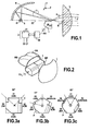
- the device which is the subject of the invention comprises at least one elliptical collector, also referred to as a reflector, denoted R, with a double focus f1, f2.
- a light source S is placed in the vicinity of one of the foci, the focus f1.
- the light source may be either a set of LEDs or a halogen source or other.
- the device which is the subject of the invention also comprises a lens L for projecting the light beam, or fi, ft, f beams delivered by the light source S according to a lighting / signaling beam F.
- the device object of the invention further comprises a multi-function beam folder, denoted 1, formed by an optical polyhedron.
- This optical polyhedron 1 is provided with a number of optical facets greater than two, which can be arranged adjacently along a generative line of the polyhedron.
- Each optical facet is provided with a folding edge / beam transmitter, this folding edge / beam transmitter generating a specific lighting / signaling function.
- the optical polyhedron 1 is placed in the path of the light beam generated by the source S between the collector R and the projection lens L, in the vicinity of the second focus f2. It transmits reflected beams and beams transmitted to the lens. focus, whose focal plane contains the focus f2.
- Each facet of the optical polyhedron 1 is provided at night with a reflective coating, if necessary partially reflecting, or with a recess, the folding edge / beam transmitter generating a specific lighting / signaling function of one of the facets being placed in the vicinity of the second focus f2.
- the folding / transmitting edge associated with the facet considered is thus orthogonal to the optical axis ZZ of the assembly and to the plane of the sheet containing the figure 1 .
- the optical polyhedron 1 is mobile at least in rotation about an axis of rotation YY orthogonal to the optical axis ZZ of the assembly including the first f1 and the second focus f2.
- the device which is the subject of the invention comprises a resource 2 for selecting and controlling at least one optical facet and the folding edge / beam transmitter associated therewith for bringing this folding / transmitting edge into position. interception of the light beam in the vicinity of the second focus f2, by controlling the rotational displacement of the optical polyhedron 1.
- the optical polyhedron 1 is thus dimensioned so as to allow the free rotation of the latter and the setting up of the facet, in particular the folding / transmitting edge, in the vicinity of the second focus f2 by simple rotation control around the axis. of rotation YY.
- the edge of the polyhedron constituting the folding / transmitting edge of the face in question is placed orthogonally to the optical axis ZZ and to the plane of the sheet of the figure 1 .
- the resource 2 for selecting and controlling at least one optical facet and the folding edge / beam transmitter thereof advantageously comprises a rotary drive motor 20 and a control module 21, which will be described in detail. later in the description. It is thus understood that the passage of one of the facets of the optical polyhedron 1 to another facet of the latter, to perform the switching of the corresponding lighting / signaling function, is thus performed by simple rotation of the optical polyhedron 1.
- the optical polyhedron 1 is represented as consisting of four facets substantially inscribed in a square. This mode of implementation is not limiting.
- optical polyhedron 1 Various alternative embodiments of the optical polyhedron 1 are shown and described in connection with the figure 2 and Figures 3a, 3b and 3c .
- the collector R is represented, in a nonlimiting manner, as constituted by a double reflector each provided with a source arranged symmetrically with respect to the optical axis ZZ.
- each facet is provided with a specific folding / transmitting edge to perform the corresponding lighting / signaling function, the optical polyhedron 1 being switched by simple rotation around the axis of rotation YY, by ordering resource 2.
- the shape and size of each facet and each corresponding bending / transmitting edge is subject to specific regulations to meet the criteria of the corresponding standard lighting / signaling functions. For this reason, the shape and size of each of the aforementioned facets will not be described in detail.
- the cross-section of the optical polyhedron 1 is advantageously inscribed in a square, C.
- a square At each side of the square is associated an optical facet and a specific folding / transmitting edge allowing the light beam to be folded in a Code beam, an ADB beam, a Route beam and a Flat beam respectively.
- the corresponding facets are designated by the name of the function they can execute. They can advantageously be assigned each of a coded reference 01.02, 03 and 04 in fact to identify the position of each of the facets and the folding edge / transmitter associated therewith, during a switching sequence for example .
- Each facet, in the case of figure 3a is included in a center angle of 90 °.
- the cross section of the optical polyhedron 1 is inscribed in a pentagon P.
- On each side of the pentagon is associated an optical facet and a specific folding / transmitting edge for folding the light beam.
- an optical facet of a bending / transmitting edge specific to the Autoroute lighting / signaling function is inserted between the optical facet and the specific bending / transmitting edge of the Code beam and the optical facet and the specific folding / transmitting edge of the ADB beam respectively.
- each of the Code, Highway, ADB, Route and Flat functions has the coded reference 01, 02, 03 04, 05 respectively.
- Each optical facet is inscribed in an angle at center of 72 °.
- the cross section of the optical polyhedron 1 is inscribed in a hexagon H.
- an optical facet and a specific folding / transmitting edge for folding the light beam is then inserted between the optical facet and the specific bending / transmitting edge of the flat bundle and the optical facet and the Specific bender / transmitter edge of Code Beam.
- each of the Code, Highway, ADB, Route, Flat and Day functions is coded as 01, 02, 03, 04, 05 and 06 respectively.
- Each optical facet is inscribed in an angle at the center of 60 °.
- the latter can be obtained by extrusion of a plastic material reinforced with fiberglass, for example.
- the different facets and folding edge / transmitter of each of these can then be easily executed from a corresponding specific mold.
- Each facet is then provided with a reflective coating formed, for example, by a metallization of silver or aluminum alloy.
- the metallization is replaced at least partially by a recess denoted e which allows the passage and transmission of the entire upper beam at the facet plane and the virtual absence of folding of this beam, to execute the conventional Route lighting beam.
- the latter corresponds to a divergent facet, introducing a dispersion and a reduction in the intensity of the light beam.
- the number of optical facets of the optical polyhedron 1 is not limited to six. Proper sizing of the latter can increase this number to seven or eight.
- the selection and control resource 2 advantageously comprises a motor 20 for rotating the optical polyhedron 1 in increments of arc of rotation corresponding to the angle at the center of each optical facet, independently of the embodiment of the number of functions described in FIG. 3a, 3b, or 3c .
- a control module 21 makes it possible to control the driving of the optical polyhedron 1 by the motor 20.
- the drive motor 20 may advantageously be constituted by a stepping motor. This type of motor makes it possible, in this application in particular, to adapt the angular rotation control of the optical polyhedron 1 to the engine rotation pitch.
- a particularly advantageous specific control mode can be implemented from the coded references assigned to each of the aforementioned facets.
- the rotation control by the module 21 can be performed from the initial coded reference Ci, corresponding to the facet and the folding edge / transmitter associated therewith in the current position of intercepting the light beam, and the coded reference final Cf to reach, corresponding to the facet and the folding edge associated with it, due to an automatic command or executed from the commodo of the vehicle by the driver of the latter. It is understood, in particular, that the calculation of the difference between the aforementioned coded reference values, the comparison of this difference in absolute value to half the number of functions implemented by the optical polyhedron 1 make it possible to determine the direction of direct rotation or retrograde optical polyhedron.
- the control of the motor is thus deduced from the number of elementary rotations corresponding to an angle at the center of each facet, limited to a number less than or equal to half the number of functions implemented by the optical polyhedron 1, to reach the lighting function. / signaling corresponding to the final coded reference Cf, by rotation in the direct or retrograde direction.
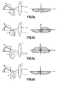
- the optical facet of the optical polyhedron 1 has its folding edge / BP transmitter, whose CP cutoff is placed in the vicinity the second focus f2. It is noted that in the case of figure 4b the CP cutoff of the BP folding / transmitting edge is more important.
- the optical facet of the optical polyhedron 1 has its recess e instead of a folding edge / transmitter, which ensures a virtually complete transmission of incident beams emitted by the source, in the absence of interception.
- the recess e appears as a cutaway allowing the aforementioned almost complete transmission.
- the Flat light / signaling function is selected.
- the optical facet of the optical polyhedron 1 has its fold edge / BP transmitter substantially centered in the vicinity of the second focus f2, in the absence of cut.
- the Figures 5a to 5d take up, in a side sectional view of Figures 4a to 4d , the respective positions of the optical facets of the optical polyhedron 1, when selecting the similar functions of Code, ADB -L, Route and Flat respectively, accompanied by the iso-intensity curves of the light beam F delivered by the lens L in a frontal plane, orthogonal to the beam and containing the x, y directions.
- the light beam F has in the upper left quadrant of the x-plane, y a substantially zero intensity, and a height-limited intensity in the upper right quadrant of this same plane, than in the case of the L-type ADB function, figure 5b , the light beam F has in the upper left quarter of the plane x, y a substantially zero intensity but a significant intensity in the upper right quarter of this same plane, intensity comparable to that of the road function in the same quarter of plane, that in the case of the Route function, figure 5c , the light beam F has a substantially symmetrical intensity diagram with respect to the vertical direction x, the intensity of the illumination being significant in the upper right and left quadrants, than in the case of the selection of the function Plat, figure 5d
- the light beam F has a substantially zero intensity pattern in the upper right and left quadrants of the same plane x, y.
- the switching is performed, as described above, by determining the direction of rotation of the optical polyhedron 1, in this situation the retrograde direction, because the number of switching arcs by rotation in the forward direction is greater than the half of the total number of functions implemented, as previously described in the description.
- the switching of each successive optical facet according to the sequence represented in FIG. figure 6a is executed with a limited optical facet switching time, for example less than or equal to 500 milliseconds.
- this switching mode makes it possible to substantially eliminate any transient secondary effect of optical switching linked to the rotation of the optical facets of the optical polyhedron 1.
- the time interval between the switching of two successive facets can be taken much lower than the switching time of an optical facet.
- the switching control and selection of an optical facet may advantageously consist in modulating the intensity of the current delivered to the light source S to attenuate, if not suppress, the intensity delivered to the latter during the switching time of the facet considered.
- the intensity of the current delivered to the light source S during the switching process of each facet being brought substantially to the zero value.
- the corresponding intensity chronogram delivered to the light source S is represented in dashed line on the figure 6b .
- the figure 7a represents a view from above of the device that is the subject of the invention as represented in figure 1 , in the preferred embodiment mentioned above.
- the same references designate the same elements.
- the plan of the figure 7a is the plane y, z of the figure 1 .
- the beam folder that is to say the optical polyhedron 1, and, where appropriate, the drive motor in rotation thereof are mounted on a plate 3 movable in translation in a direction y orthogonal to the optical axis ZZ of the assembly including the first focus f1 and the second focus f2.
- the folding edge / transmitter BP being placed substantially at the second focus f2
- the aforementioned translation is operated for the entire folding edge / BP transmitter in the focal plane of the focusing lens L.
- the aforementioned translation and allows to shift the entire light beam F in the plane of the figure 7a either in the plane containing the directions y and z of the aforementioned figure.
- a drive motor in translation denoted 4.
- the latter is preferably a DC motor, because of the control accuracy of this type of motor.
- the output shaft of the aforementioned direct current motor may advantageously be coupled to a reduction system, not shown in the drawing, to enable the displacement in translation of the assembly formed by the plate 3 and the Optical polyhedron 1.
- the transmission system by gearbox or gear, of conventional type, will not be described in detail.
- the device which is the subject of the invention, as represented in figure 7a makes it possible to carry out an illumination tracking of a third-party vehicle VT, in order to prevent any glare from the driver of the latter under the following conditions.
- control module 21b presents the specific architecture completed, as represented in figure 7b .
- a camera is provided on board a vehicle equipped with the device object of the invention, vehicle noted VE.
- the equipment of the latter consists of a device according to the object of the invention applied to each of the headlights of the equipped vehicle. It is understood, in particular, that while a single camera and a control unit are used for a given equipped vehicle, the left and right front headlight thereof includes, if necessary, an independent control module 21 b allocated at each respective lighthouse. On the figure 7b only a control module 21b has been shown, so as not to overload the drawing.
- the above-mentioned control module 21b is associated with a DBL control unit 22 which is directly connected to the general control unit of the vehicle.
- the control module 21 performs the beam selection, i.e., lighting / signaling function comparable to the beam selection control module 21 shown in FIG. figure 1 .
- the camera detects the third party vehicle VT in the far position.
- the right light beams Fd and left Fg are both switched to the function
- the above-mentioned beams show the iso-intensity diagram as represented in FIG. figure 5d , symmetrical with respect to the longitudinal axis of VE equipped vehicle.
- the tracking function is started by the camera and executed by the control unit and of course, the control module 22, which controls the translational movement of the optical polyhedron 1, via the motor 4, to shift , depending on the approach of the third vehicle VT, the right beam Fd angularly to the left.
- This operation is performed by controlling the engine 4 and continued to the position 3 of the third vehicle VT, corresponding substantially to the minimum illumination distance for a light beam type L.
- the beam left Fg is not modified.
- the right beam may be switched by rotating the optical polyhedron 1 to select, for example, the lighting / signaling function Code for the right beam Fd, as shown in position 4.
- the right beam Fd can be switched again, and the left beam Fg, by selecting the Route lighting / signaling function for example, for each of the aforementioned bundles.
- the process of tracking the third-party vehicle VT is not limited to the circulation of a third-party vehicle in the opposite direction to the equipped vehicle. This process also applies to any third-party vehicle preceding the VE-equipped vehicle, which VE is approaching. The beam switching and tracking sequences are then adapted accordingly.
- tracking function known as such to those skilled in the art, will not be described in detail but that this function can be applied in combination to any type of light beam having a longitudinal asymmetry of illumination to create a dark area ZS.
Landscapes
- Engineering & Computer Science (AREA)
- General Engineering & Computer Science (AREA)
- Physics & Mathematics (AREA)
- Microelectronics & Electronic Packaging (AREA)
- Optics & Photonics (AREA)
- Lighting Device Outwards From Vehicle And Optical Signal (AREA)
- Non-Portable Lighting Devices Or Systems Thereof (AREA)
Applications Claiming Priority (1)
| Application Number | Priority Date | Filing Date | Title |
|---|---|---|---|
| FR1156396A FR2977927B1 (fr) | 2011-07-13 | 2011-07-13 | Dispositif d'eclairage/signalisation multifonctions pour vehicule automobile. |
Publications (3)
| Publication Number | Publication Date |
|---|---|
| EP2546569A2 true EP2546569A2 (de) | 2013-01-16 |
| EP2546569A3 EP2546569A3 (de) | 2013-03-13 |
| EP2546569B1 EP2546569B1 (de) | 2014-03-12 |
Family
ID=46397115
Family Applications (1)
| Application Number | Title | Priority Date | Filing Date |
|---|---|---|---|
| EP12175597.9A Active EP2546569B1 (de) | 2011-07-13 | 2012-07-09 | Multifunktions-Beleuchtungs-/Signalisierungsvorrichtung für Kraftfahrzeug |
Country Status (2)
| Country | Link |
|---|---|
| EP (1) | EP2546569B1 (de) |
| FR (1) | FR2977927B1 (de) |
Cited By (8)
| Publication number | Priority date | Publication date | Assignee | Title |
|---|---|---|---|---|
| EP2853804A1 (de) * | 2013-09-30 | 2015-04-01 | Valeo Vision | Beleuchtungs- und/oder Signalisierungsmodul mit mehreren drehbaren optischen Systemen |
| FR3025151A1 (fr) * | 2014-08-29 | 2016-03-04 | Valeo Vision | Procede de controle d'un faisceau lumineux et module d'eclairage et/ou de signalisation correspondant |
| FR3028005A1 (fr) * | 2014-10-30 | 2016-05-06 | Aml Systems | Projecteur semi-elliptique a moyen de mise en mouvement situe en amont de l'element optique mobile |
| FR3028002A1 (fr) * | 2014-10-30 | 2016-05-06 | Aml Systems | Projecteur semi-elliptique a miroir mobile pour vehicule automobile |
| EP3369987A1 (de) * | 2017-03-01 | 2018-09-05 | Hella Saturnus Slovenija, Proizvodnja svetlobne opreme za motorna in druga vozila, d.o.o. | Fahrzeugscheinwerfer |
| EP3382265A1 (de) * | 2017-03-30 | 2018-10-03 | LG Electronics Inc. | Scheinwerfer für ein fahrzeug |
| CN109027956A (zh) * | 2017-04-14 | 2018-12-18 | 武汉流塑自动化装备有限公司 | 一种自适应前照灯调光机构 |
| DE102016105730B4 (de) | 2015-03-30 | 2023-09-28 | PO LIGHTING CZECH s.r.o. | Vorrichtung und Verfahren zum Reduzieren von Rändern des Lichtbilds eines Scheinwerfers und Scheinwerfer mit der Vorrichtung |
Citations (2)
| Publication number | Priority date | Publication date | Assignee | Title |
|---|---|---|---|---|
| EP2199664A1 (de) | 2008-12-19 | 2010-06-23 | Valeo Vision | Beleuchtungsvorrichtung für Fahrzeugscheinwerfer, der mehrere Beleuchtungsfunktionen oder eine veränderbare Funktion mit einer einzigen Lichtquelle ermöglicht |
| EP2244007A1 (de) | 2009-04-24 | 2010-10-27 | Valeo Vision | Optische Vorrichtung für Kraftfahrzeug |
Family Cites Families (3)
| Publication number | Priority date | Publication date | Assignee | Title |
|---|---|---|---|---|
| DE19909413A1 (de) * | 1999-03-04 | 2000-09-07 | Hella Kg Hueck & Co | Scheinwerfer für Fahrzeuge |
| DE102008010028B4 (de) * | 2008-02-20 | 2016-12-08 | Hella Kgaa Hueck & Co. | Projektionsscheinwerfer für Fahrzeuge |
| FR2953468B1 (fr) * | 2009-12-08 | 2012-05-25 | Valeo Vision | Module optique apte a generer un faisceau lumineux de type code et un faisceau lumineux selectif |
-
2011
- 2011-07-13 FR FR1156396A patent/FR2977927B1/fr not_active Expired - Fee Related
-
2012
- 2012-07-09 EP EP12175597.9A patent/EP2546569B1/de active Active
Patent Citations (2)
| Publication number | Priority date | Publication date | Assignee | Title |
|---|---|---|---|---|
| EP2199664A1 (de) | 2008-12-19 | 2010-06-23 | Valeo Vision | Beleuchtungsvorrichtung für Fahrzeugscheinwerfer, der mehrere Beleuchtungsfunktionen oder eine veränderbare Funktion mit einer einzigen Lichtquelle ermöglicht |
| EP2244007A1 (de) | 2009-04-24 | 2010-10-27 | Valeo Vision | Optische Vorrichtung für Kraftfahrzeug |
Cited By (10)
| Publication number | Priority date | Publication date | Assignee | Title |
|---|---|---|---|---|
| EP2853804A1 (de) * | 2013-09-30 | 2015-04-01 | Valeo Vision | Beleuchtungs- und/oder Signalisierungsmodul mit mehreren drehbaren optischen Systemen |
| FR3025151A1 (fr) * | 2014-08-29 | 2016-03-04 | Valeo Vision | Procede de controle d'un faisceau lumineux et module d'eclairage et/ou de signalisation correspondant |
| EP2990264A3 (de) * | 2014-08-29 | 2016-03-09 | Valeo Vision | Steuerungsverfahren eins lichtstrahls und entsprechendes beleuchtungs- und/oder signalisierungsmodul |
| FR3028005A1 (fr) * | 2014-10-30 | 2016-05-06 | Aml Systems | Projecteur semi-elliptique a moyen de mise en mouvement situe en amont de l'element optique mobile |
| FR3028002A1 (fr) * | 2014-10-30 | 2016-05-06 | Aml Systems | Projecteur semi-elliptique a miroir mobile pour vehicule automobile |
| DE102016105730B4 (de) | 2015-03-30 | 2023-09-28 | PO LIGHTING CZECH s.r.o. | Vorrichtung und Verfahren zum Reduzieren von Rändern des Lichtbilds eines Scheinwerfers und Scheinwerfer mit der Vorrichtung |
| EP3369987A1 (de) * | 2017-03-01 | 2018-09-05 | Hella Saturnus Slovenija, Proizvodnja svetlobne opreme za motorna in druga vozila, d.o.o. | Fahrzeugscheinwerfer |
| EP3382265A1 (de) * | 2017-03-30 | 2018-10-03 | LG Electronics Inc. | Scheinwerfer für ein fahrzeug |
| US10501012B2 (en) | 2017-03-30 | 2019-12-10 | Lg Electronics Inc. | Lamp for vehicle, and vehicle |
| CN109027956A (zh) * | 2017-04-14 | 2018-12-18 | 武汉流塑自动化装备有限公司 | 一种自适应前照灯调光机构 |
Also Published As
| Publication number | Publication date |
|---|---|
| FR2977927A1 (fr) | 2013-01-18 |
| FR2977927B1 (fr) | 2013-08-23 |
| EP2546569A3 (de) | 2013-03-13 |
| EP2546569B1 (de) | 2014-03-12 |
Similar Documents
| Publication | Publication Date | Title |
|---|---|---|
| EP2546569B1 (de) | Multifunktions-Beleuchtungs-/Signalisierungsvorrichtung für Kraftfahrzeug | |
| EP2690352B1 (de) | Adaptives Beleuchtungssystem für Kraftfahrzeug | |
| EP2957464B1 (de) | Drehbares beleuchtungs- und/oder signalisierungsmodul | |
| EP3115256A1 (de) | Kontrollverfahren eines lichtbündels, und entsprechendes beleuchtungs- und/oder signalisierungsmodul | |
| EP3027961A1 (de) | Projektor und beleuchtungssystem, insbesondere für ein kraftfahrzeug | |
| EP2957822A1 (de) | Drehbares beleuchtungs- und/oder signalisierungsmodul | |
| EP2957821B1 (de) | Drehbares beleuchtungs- und/oder signalisierungsmodul | |
| EP3152480A1 (de) | Beleuchtungsvorrichtung mit beweglicher linse für kraftfahrzeug | |
| EP2957819A1 (de) | Drehbares beleuchtungs- und/oder signalisierungsmodul | |
| EP2957823B1 (de) | Drehbares beleuchtungs- und/oder signalisierungsmodul | |
| EP2436968B1 (de) | Vorrichtung zur Ausstrahlung von Licht für einen Autoscheinwerfer | |
| EP3124856B1 (de) | Beleuchtungsvorrichtung für kraftfahrzeug | |
| EP2957820B1 (de) | Drehbares beleuchtungs- und/oder signalisierungsmodul | |
| EP1835325A2 (de) | Infrarot-Beleuchtungsmodul für Kraftfahrzeugscheinwerfer und Scheinwerfer, der mit einem solchen Modul ausgestattet ist | |
| EP1870283B1 (de) | Scheinwerfereinheit mit drei Funktionen für Kraftfahrzeuge | |
| EP2853804B1 (de) | Beleuchtungs- und/oder signalisierungsmodul mit mehreren drehbaren optischen systemen | |
| EP3227139A1 (de) | Mobile follow-me-home-beleuchtungs- und/oder anzeigevorrichtung für ein kraftfahrzeug | |
| EP3436307B1 (de) | Fahrzeugscheinwerfer | |
| FR3025290B1 (fr) | Module d'eclairage multifonction pour vehicule automobile | |
| EP2944514A1 (de) | Beleuchtungsmodul für kraftfahrzeugscheinwerfer, das mehrere lichtquellen umfasst | |
| EP3197717B1 (de) | Kraftfahrzeug mit einer signalisierungsvorrichtung mit beweglicher anordnung | |
| FR3022323A1 (fr) | Module d'eclairage et/ou de signalisation rotatif | |
| EP1953039A2 (de) | Multifunktionsbeleuchtungsvorrichtung für Kraftfahrzeug | |
| EP2196731A1 (de) | Optisches Scheinwerfermodul für Kraftfahrzeug mit mobiler Abdeckung |
Legal Events
| Date | Code | Title | Description |
|---|---|---|---|
| PUAI | Public reference made under article 153(3) epc to a published international application that has entered the european phase |
Free format text: ORIGINAL CODE: 0009012 |
|
| AK | Designated contracting states |
Kind code of ref document: A2 Designated state(s): AL AT BE BG CH CY CZ DE DK EE ES FI FR GB GR HR HU IE IS IT LI LT LU LV MC MK MT NL NO PL PT RO RS SE SI SK SM TR |
|
| AX | Request for extension of the european patent |
Extension state: BA ME |
|
| PUAL | Search report despatched |
Free format text: ORIGINAL CODE: 0009013 |
|
| AK | Designated contracting states |
Kind code of ref document: A3 Designated state(s): AL AT BE BG CH CY CZ DE DK EE ES FI FR GB GR HR HU IE IS IT LI LT LU LV MC MK MT NL NO PL PT RO RS SE SI SK SM TR |
|
| AX | Request for extension of the european patent |
Extension state: BA ME |
|
| RIC1 | Information provided on ipc code assigned before grant |
Ipc: F21W 101/10 20060101ALN20130207BHEP Ipc: F21S 8/12 20060101AFI20130207BHEP Ipc: F21Y 101/02 20060101ALN20130207BHEP Ipc: F21V 14/08 20060101ALI20130207BHEP |
|
| 17P | Request for examination filed |
Effective date: 20130807 |
|
| RBV | Designated contracting states (corrected) |
Designated state(s): AL AT BE BG CH CY CZ DE DK EE ES FI FR GB GR HR HU IE IS IT LI LT LU LV MC MK MT NL NO PL PT RO RS SE SI SK SM TR |
|
| RIC1 | Information provided on ipc code assigned before grant |
Ipc: F21W 101/10 20060101ALN20130904BHEP Ipc: F21S 8/12 20060101AFI20130904BHEP Ipc: F21V 14/08 20060101ALI20130904BHEP Ipc: F21Y 101/02 20060101ALN20130904BHEP |
|
| GRAP | Despatch of communication of intention to grant a patent |
Free format text: ORIGINAL CODE: EPIDOSNIGR1 |
|
| RIC1 | Information provided on ipc code assigned before grant |
Ipc: F21V 14/08 20060101ALI20130910BHEP Ipc: F21S 8/12 20060101AFI20130910BHEP Ipc: F21Y 101/02 20060101ALN20130910BHEP Ipc: F21W 101/10 20060101ALN20130910BHEP |
|
| INTG | Intention to grant announced |
Effective date: 20131010 |
|
| GRAS | Grant fee paid |
Free format text: ORIGINAL CODE: EPIDOSNIGR3 |
|
| GRAA | (expected) grant |
Free format text: ORIGINAL CODE: 0009210 |
|
| AK | Designated contracting states |
Kind code of ref document: B1 Designated state(s): AL AT BE BG CH CY CZ DE DK EE ES FI FR GB GR HR HU IE IS IT LI LT LU LV MC MK MT NL NO PL PT RO RS SE SI SK SM TR |
|
| REG | Reference to a national code |
Ref country code: GB Ref legal event code: FG4D Free format text: NOT ENGLISH |
|
| REG | Reference to a national code |
Ref country code: CH Ref legal event code: EP |
|
| REG | Reference to a national code |
Ref country code: AT Ref legal event code: REF Ref document number: 656548 Country of ref document: AT Kind code of ref document: T Effective date: 20140315 |
|
| REG | Reference to a national code |
Ref country code: IE Ref legal event code: FG4D Free format text: LANGUAGE OF EP DOCUMENT: FRENCH |
|
| REG | Reference to a national code |
Ref country code: DE Ref legal event code: R096 Ref document number: 602012001004 Country of ref document: DE Effective date: 20140424 |
|
| REG | Reference to a national code |
Ref country code: NL Ref legal event code: VDEP Effective date: 20140312 |
|
| PG25 | Lapsed in a contracting state [announced via postgrant information from national office to epo] |
Ref country code: LT Free format text: LAPSE BECAUSE OF FAILURE TO SUBMIT A TRANSLATION OF THE DESCRIPTION OR TO PAY THE FEE WITHIN THE PRESCRIBED TIME-LIMIT Effective date: 20140312 Ref country code: NO Free format text: LAPSE BECAUSE OF FAILURE TO SUBMIT A TRANSLATION OF THE DESCRIPTION OR TO PAY THE FEE WITHIN THE PRESCRIBED TIME-LIMIT Effective date: 20140612 |
|
| REG | Reference to a national code |
Ref country code: AT Ref legal event code: MK05 Ref document number: 656548 Country of ref document: AT Kind code of ref document: T Effective date: 20140312 |
|
| REG | Reference to a national code |
Ref country code: LT Ref legal event code: MG4D |
|
| PG25 | Lapsed in a contracting state [announced via postgrant information from national office to epo] |
Ref country code: FI Free format text: LAPSE BECAUSE OF FAILURE TO SUBMIT A TRANSLATION OF THE DESCRIPTION OR TO PAY THE FEE WITHIN THE PRESCRIBED TIME-LIMIT Effective date: 20140312 Ref country code: SE Free format text: LAPSE BECAUSE OF FAILURE TO SUBMIT A TRANSLATION OF THE DESCRIPTION OR TO PAY THE FEE WITHIN THE PRESCRIBED TIME-LIMIT Effective date: 20140312 Ref country code: CY Free format text: LAPSE BECAUSE OF FAILURE TO SUBMIT A TRANSLATION OF THE DESCRIPTION OR TO PAY THE FEE WITHIN THE PRESCRIBED TIME-LIMIT Effective date: 20140312 |
|
| PG25 | Lapsed in a contracting state [announced via postgrant information from national office to epo] |
Ref country code: LV Free format text: LAPSE BECAUSE OF FAILURE TO SUBMIT A TRANSLATION OF THE DESCRIPTION OR TO PAY THE FEE WITHIN THE PRESCRIBED TIME-LIMIT Effective date: 20140312 Ref country code: RS Free format text: LAPSE BECAUSE OF FAILURE TO SUBMIT A TRANSLATION OF THE DESCRIPTION OR TO PAY THE FEE WITHIN THE PRESCRIBED TIME-LIMIT Effective date: 20140312 Ref country code: HR Free format text: LAPSE BECAUSE OF FAILURE TO SUBMIT A TRANSLATION OF THE DESCRIPTION OR TO PAY THE FEE WITHIN THE PRESCRIBED TIME-LIMIT Effective date: 20140312 |
|
| PG25 | Lapsed in a contracting state [announced via postgrant information from national office to epo] |
Ref country code: BG Free format text: LAPSE BECAUSE OF FAILURE TO SUBMIT A TRANSLATION OF THE DESCRIPTION OR TO PAY THE FEE WITHIN THE PRESCRIBED TIME-LIMIT Effective date: 20140612 Ref country code: EE Free format text: LAPSE BECAUSE OF FAILURE TO SUBMIT A TRANSLATION OF THE DESCRIPTION OR TO PAY THE FEE WITHIN THE PRESCRIBED TIME-LIMIT Effective date: 20140312 Ref country code: RO Free format text: LAPSE BECAUSE OF FAILURE TO SUBMIT A TRANSLATION OF THE DESCRIPTION OR TO PAY THE FEE WITHIN THE PRESCRIBED TIME-LIMIT Effective date: 20140312 Ref country code: CZ Free format text: LAPSE BECAUSE OF FAILURE TO SUBMIT A TRANSLATION OF THE DESCRIPTION OR TO PAY THE FEE WITHIN THE PRESCRIBED TIME-LIMIT Effective date: 20140312 Ref country code: IS Free format text: LAPSE BECAUSE OF FAILURE TO SUBMIT A TRANSLATION OF THE DESCRIPTION OR TO PAY THE FEE WITHIN THE PRESCRIBED TIME-LIMIT Effective date: 20140712 Ref country code: NL Free format text: LAPSE BECAUSE OF FAILURE TO SUBMIT A TRANSLATION OF THE DESCRIPTION OR TO PAY THE FEE WITHIN THE PRESCRIBED TIME-LIMIT Effective date: 20140312 |
|
| PG25 | Lapsed in a contracting state [announced via postgrant information from national office to epo] |
Ref country code: SK Free format text: LAPSE BECAUSE OF FAILURE TO SUBMIT A TRANSLATION OF THE DESCRIPTION OR TO PAY THE FEE WITHIN THE PRESCRIBED TIME-LIMIT Effective date: 20140312 Ref country code: AT Free format text: LAPSE BECAUSE OF FAILURE TO SUBMIT A TRANSLATION OF THE DESCRIPTION OR TO PAY THE FEE WITHIN THE PRESCRIBED TIME-LIMIT Effective date: 20140312 Ref country code: ES Free format text: LAPSE BECAUSE OF FAILURE TO SUBMIT A TRANSLATION OF THE DESCRIPTION OR TO PAY THE FEE WITHIN THE PRESCRIBED TIME-LIMIT Effective date: 20140312 Ref country code: PL Free format text: LAPSE BECAUSE OF FAILURE TO SUBMIT A TRANSLATION OF THE DESCRIPTION OR TO PAY THE FEE WITHIN THE PRESCRIBED TIME-LIMIT Effective date: 20140312 |
|
| REG | Reference to a national code |
Ref country code: DE Ref legal event code: R097 Ref document number: 602012001004 Country of ref document: DE |
|
| PG25 | Lapsed in a contracting state [announced via postgrant information from national office to epo] |
Ref country code: PT Free format text: LAPSE BECAUSE OF FAILURE TO SUBMIT A TRANSLATION OF THE DESCRIPTION OR TO PAY THE FEE WITHIN THE PRESCRIBED TIME-LIMIT Effective date: 20140714 |
|
| PLBE | No opposition filed within time limit |
Free format text: ORIGINAL CODE: 0009261 |
|
| STAA | Information on the status of an ep patent application or granted ep patent |
Free format text: STATUS: NO OPPOSITION FILED WITHIN TIME LIMIT |
|
| PG25 | Lapsed in a contracting state [announced via postgrant information from national office to epo] |
Ref country code: DK Free format text: LAPSE BECAUSE OF FAILURE TO SUBMIT A TRANSLATION OF THE DESCRIPTION OR TO PAY THE FEE WITHIN THE PRESCRIBED TIME-LIMIT Effective date: 20140312 |
|
| 26N | No opposition filed |
Effective date: 20141215 |
|
| PG25 | Lapsed in a contracting state [announced via postgrant information from national office to epo] |
Ref country code: RS Free format text: LAPSE BECAUSE OF FAILURE TO SUBMIT A TRANSLATION OF THE DESCRIPTION OR TO PAY THE FEE WITHIN THE PRESCRIBED TIME-LIMIT Effective date: 20140903 Ref country code: LU Free format text: LAPSE BECAUSE OF FAILURE TO SUBMIT A TRANSLATION OF THE DESCRIPTION OR TO PAY THE FEE WITHIN THE PRESCRIBED TIME-LIMIT Effective date: 20140709 |
|
| REG | Reference to a national code |
Ref country code: DE Ref legal event code: R097 Ref document number: 602012001004 Country of ref document: DE Effective date: 20141215 |
|
| PG25 | Lapsed in a contracting state [announced via postgrant information from national office to epo] |
Ref country code: IT Free format text: LAPSE BECAUSE OF FAILURE TO SUBMIT A TRANSLATION OF THE DESCRIPTION OR TO PAY THE FEE WITHIN THE PRESCRIBED TIME-LIMIT Effective date: 20140312 |
|
| REG | Reference to a national code |
Ref country code: IE Ref legal event code: MM4A |
|
| PG25 | Lapsed in a contracting state [announced via postgrant information from national office to epo] |
Ref country code: SI Free format text: LAPSE BECAUSE OF FAILURE TO SUBMIT A TRANSLATION OF THE DESCRIPTION OR TO PAY THE FEE WITHIN THE PRESCRIBED TIME-LIMIT Effective date: 20140312 |
|
| PG25 | Lapsed in a contracting state [announced via postgrant information from national office to epo] |
Ref country code: IE Free format text: LAPSE BECAUSE OF NON-PAYMENT OF DUE FEES Effective date: 20140709 |
|
| REG | Reference to a national code |
Ref country code: CH Ref legal event code: PL |
|
| PG25 | Lapsed in a contracting state [announced via postgrant information from national office to epo] |
Ref country code: CH Free format text: LAPSE BECAUSE OF NON-PAYMENT OF DUE FEES Effective date: 20150731 Ref country code: LI Free format text: LAPSE BECAUSE OF NON-PAYMENT OF DUE FEES Effective date: 20150731 Ref country code: MC Free format text: LAPSE BECAUSE OF FAILURE TO SUBMIT A TRANSLATION OF THE DESCRIPTION OR TO PAY THE FEE WITHIN THE PRESCRIBED TIME-LIMIT Effective date: 20140312 Ref country code: SM Free format text: LAPSE BECAUSE OF FAILURE TO SUBMIT A TRANSLATION OF THE DESCRIPTION OR TO PAY THE FEE WITHIN THE PRESCRIBED TIME-LIMIT Effective date: 20140312 |
|
| PG25 | Lapsed in a contracting state [announced via postgrant information from national office to epo] |
Ref country code: MT Free format text: LAPSE BECAUSE OF FAILURE TO SUBMIT A TRANSLATION OF THE DESCRIPTION OR TO PAY THE FEE WITHIN THE PRESCRIBED TIME-LIMIT Effective date: 20140312 Ref country code: GR Free format text: LAPSE BECAUSE OF FAILURE TO SUBMIT A TRANSLATION OF THE DESCRIPTION OR TO PAY THE FEE WITHIN THE PRESCRIBED TIME-LIMIT Effective date: 20140613 |
|
| PG25 | Lapsed in a contracting state [announced via postgrant information from national office to epo] |
Ref country code: BE Free format text: LAPSE BECAUSE OF FAILURE TO SUBMIT A TRANSLATION OF THE DESCRIPTION OR TO PAY THE FEE WITHIN THE PRESCRIBED TIME-LIMIT Effective date: 20140731 Ref country code: HU Free format text: LAPSE BECAUSE OF FAILURE TO SUBMIT A TRANSLATION OF THE DESCRIPTION OR TO PAY THE FEE WITHIN THE PRESCRIBED TIME-LIMIT; INVALID AB INITIO Effective date: 20120709 Ref country code: TR Free format text: LAPSE BECAUSE OF FAILURE TO SUBMIT A TRANSLATION OF THE DESCRIPTION OR TO PAY THE FEE WITHIN THE PRESCRIBED TIME-LIMIT Effective date: 20140312 |
|
| REG | Reference to a national code |
Ref country code: FR Ref legal event code: PLFP Year of fee payment: 5 |
|
| GBPC | Gb: european patent ceased through non-payment of renewal fee |
Effective date: 20160709 |
|
| PG25 | Lapsed in a contracting state [announced via postgrant information from national office to epo] |
Ref country code: GB Free format text: LAPSE BECAUSE OF NON-PAYMENT OF DUE FEES Effective date: 20160709 |
|
| REG | Reference to a national code |
Ref country code: FR Ref legal event code: PLFP Year of fee payment: 6 |
|
| REG | Reference to a national code |
Ref country code: DE Ref legal event code: R079 Ref document number: 602012001004 Country of ref document: DE Free format text: PREVIOUS MAIN CLASS: F21S0008120000 Ipc: F21S0041000000 |
|
| PG25 | Lapsed in a contracting state [announced via postgrant information from national office to epo] |
Ref country code: MK Free format text: LAPSE BECAUSE OF FAILURE TO SUBMIT A TRANSLATION OF THE DESCRIPTION OR TO PAY THE FEE WITHIN THE PRESCRIBED TIME-LIMIT Effective date: 20140312 |
|
| REG | Reference to a national code |
Ref country code: FR Ref legal event code: PLFP Year of fee payment: 7 |
|
| PG25 | Lapsed in a contracting state [announced via postgrant information from national office to epo] |
Ref country code: AL Free format text: LAPSE BECAUSE OF FAILURE TO SUBMIT A TRANSLATION OF THE DESCRIPTION OR TO PAY THE FEE WITHIN THE PRESCRIBED TIME-LIMIT Effective date: 20140312 |
|
| RIC2 | Information provided on ipc code assigned after grant |
Ipc: F21S 8/12 20060101AFI20130910BHEP Ipc: F21Y 101/02 20000101ALN20130910BHEP Ipc: F21W 101/10 20060101ALN20130910BHEP Ipc: F21V 14/08 20060101ALI20130910BHEP |
|
| P01 | Opt-out of the competence of the unified patent court (upc) registered |
Effective date: 20230528 |
|
| PGFP | Annual fee paid to national office [announced via postgrant information from national office to epo] |
Ref country code: FR Payment date: 20230727 Year of fee payment: 12 Ref country code: DE Payment date: 20230712 Year of fee payment: 12 |