EP2546513A2 - Wind farm assembly and turbine therefor - Google Patents
Wind farm assembly and turbine therefor Download PDFInfo
- Publication number
- EP2546513A2 EP2546513A2 EP20120175942 EP12175942A EP2546513A2 EP 2546513 A2 EP2546513 A2 EP 2546513A2 EP 20120175942 EP20120175942 EP 20120175942 EP 12175942 A EP12175942 A EP 12175942A EP 2546513 A2 EP2546513 A2 EP 2546513A2
- Authority
- EP
- European Patent Office
- Prior art keywords
- turbine
- wind
- turbine wheel
- flow
- air
- Prior art date
- Legal status (The legal status is an assumption and is not a legal conclusion. Google has not performed a legal analysis and makes no representation as to the accuracy of the status listed.)
- Withdrawn
Links
- XLYOFNOQVPJJNP-UHFFFAOYSA-N water Substances O XLYOFNOQVPJJNP-UHFFFAOYSA-N 0.000 claims abstract description 29
- 230000001133 acceleration Effects 0.000 claims description 11
- 230000003247 decreasing effect Effects 0.000 claims description 4
- 238000010792 warming Methods 0.000 claims 1
- 238000000034 method Methods 0.000 abstract description 5
- 239000007789 gas Substances 0.000 abstract description 4
- 239000007788 liquid Substances 0.000 abstract description 3
- 238000004064 recycling Methods 0.000 abstract 1
- 239000003381 stabilizer Substances 0.000 abstract 1
- 238000006243 chemical reaction Methods 0.000 description 9
- 239000012530 fluid Substances 0.000 description 8
- 230000000694 effects Effects 0.000 description 3
- 238000004519 manufacturing process Methods 0.000 description 2
- 238000005457 optimization Methods 0.000 description 2
- 101100498160 Mus musculus Dach1 gene Proteins 0.000 description 1
- 239000003570 air Substances 0.000 description 1
- 238000000418 atomic force spectrum Methods 0.000 description 1
- 239000000969 carrier Substances 0.000 description 1
- 230000000295 complement effect Effects 0.000 description 1
- 230000005611 electricity Effects 0.000 description 1
- 230000002349 favourable effect Effects 0.000 description 1
- 238000009434 installation Methods 0.000 description 1
- 230000001788 irregular Effects 0.000 description 1
- 238000012986 modification Methods 0.000 description 1
- 230000004048 modification Effects 0.000 description 1
- 238000011084 recovery Methods 0.000 description 1
- 230000000630 rising effect Effects 0.000 description 1
- 239000007787 solid Substances 0.000 description 1
- 238000009987 spinning Methods 0.000 description 1
- 239000013589 supplement Substances 0.000 description 1
- 239000003643 water by type Substances 0.000 description 1
Images


Classifications
-
- F—MECHANICAL ENGINEERING; LIGHTING; HEATING; WEAPONS; BLASTING
- F03—MACHINES OR ENGINES FOR LIQUIDS; WIND, SPRING, OR WEIGHT MOTORS; PRODUCING MECHANICAL POWER OR A REACTIVE PROPULSIVE THRUST, NOT OTHERWISE PROVIDED FOR
- F03D—WIND MOTORS
- F03D1/00—Wind motors with rotation axis substantially parallel to the air flow entering the rotor
- F03D1/06—Rotors
- F03D1/0608—Rotors characterised by their aerodynamic shape
-
- Y—GENERAL TAGGING OF NEW TECHNOLOGICAL DEVELOPMENTS; GENERAL TAGGING OF CROSS-SECTIONAL TECHNOLOGIES SPANNING OVER SEVERAL SECTIONS OF THE IPC; TECHNICAL SUBJECTS COVERED BY FORMER USPC CROSS-REFERENCE ART COLLECTIONS [XRACs] AND DIGESTS
- Y02—TECHNOLOGIES OR APPLICATIONS FOR MITIGATION OR ADAPTATION AGAINST CLIMATE CHANGE
- Y02E—REDUCTION OF GREENHOUSE GAS [GHG] EMISSIONS, RELATED TO ENERGY GENERATION, TRANSMISSION OR DISTRIBUTION
- Y02E10/00—Energy generation through renewable energy sources
- Y02E10/70—Wind energy
- Y02E10/72—Wind turbines with rotation axis in wind direction
Definitions
- the present invention relates to a wind turbine with the features of independent claim 1.
- Wind turbines which have become known in various embodiments.
- the most well-known and almost exclusively used for large systems variant are standing on masts, axially flowed and flowed through rotors with two or three rotor blades, the rotor interacts either directly or via a reduction gear with an electric generator.
- the diameter of these rotors can be up to 90 meters or even more in so-called large-scale systems.
- there are numerous smaller plants with lower power which are mainly used for decentralized energy supply and / or to supplement other energy sources.
- a similar turbine for use in vehicles to gain energy while driving is from the DE 20 2009 013 425 U1 known.
- An additional feed hopper is to improve the flow of the turbine by steering the inflow flow.
- the DE 10 2005 049 794 A1 discloses a propeller having baffles on the surfaces of its propeller blades intended to provide improved axial deflection of the incoming fluid to the surfaces of the propeller blades and for improved axial discharge downstream of the propeller blade.
- the turbulence occurring behind the propeller area should be reduced.
- the guide structures have arcuate curvature and extend in the direction of rotation of the propeller.
- a compact wind turbine which should be particularly suitable for private users, is in the DE 10 2008 025 719 A1 proposed.
- An axially flowing air stream impinges on a drive disk with the rotation axis arranged around and perpendicular slats protruding from the drive disk, so that the air flow is discharged radially while driving the drive disk.
- the drive pulley is received in a housing having an axial inlet and a radial outlet.
- the DE 10 2008 046 209 A1 finally discloses a turbine wheel for gaseous media, in particular for a wind flow, which is fed axially centered to the impeller, where it is deflected in the region of the impeller base and then flows through the blade grid from the inside to the outside.
- the turbine runner is connected to a generator which is used to generate electricity.
- An object of the invention is to provide an impeller for a wind turbine, which is axially impinged and radially deflects the air under rotary drive of the impeller, which has an improved efficiency compared to known through an improved design of the impellers and / or guide surfaces.
- the invention proposes a wind power plant for converting flow energy transported by air into rotary mechanical and / or electrical energy, which comprises at least one turbine runner that flows essentially axially and leaves the air in approximately the radial direction.
- This turbine wheel has a rotatably mounted disk-shaped carrier with a flow-guiding structure in the form of obliquely and / or curved webs and / or channels. It is envisaged that the webs or channels each have variable or changing cross sections over their longitudinal course.
- variable cross sections of the webs, channels or the air-conducting profilings in the turbine runner may in particular resemble an airfoil profile and have an initially increasing and then decreasing thickness or thickness of the cross section in the flow direction.
- the webs the transfer of the flow energy of the fluid flowing through the impeller - the wind, water o. The like. - Partially referred to as sliding vanes.
- the terms "webs", “wings”, “glides” etc. are therefore usually to be regarded as synonyms.
- wind turbine or “wind turbine” is therefore to be understood as meaning that it may also mean hydropower plants or water turbines which operate on the same principle of flow deflection from axial flow into radial flow.
- the turbine or turbine runner of the wind turbine according to the invention has a plurality of approximately uniformly distributed over the outer region of the front surface webs - also referred to as sliding surfaces or sliding - on whose surfaces each have a curved course whose curvature in particular can correspond to the predetermined curve of a Coriolis acceleration.
- This provides a mode of energy production from the flow energy of air, gases and fluids by means of at least one turbine impeller, which follows or at least resembles the principle of Coriolis acceleration. In this way, extremely compact wind energy or water power plants can be provided, which have a high efficiency and a high energy density.
- the sailing characteristics also apply because a light vehicle equipped with a cylinder turbine can, with appropriate reduction, drive against the wind solely with the energy contained in the moving air.
- the possibility of recovering drive energy in different vehicles is used as a savings option of energy.
- the displaced by a motor vehicle medium gives its resulting from the drive kinetic energy almost exclusively to the environment (eg wind pressure and moving plants on the roadside) from.
- the airstream represents an energy form caused by the vehicle itself, which one seeks to reduce by a favorable CW value, but at the same time represents a potential for recovery, which is at least partially usable.
- the turbine wheel of the wind power plant according to the invention can optionally have a plurality of approximately uniformly distributed over the outer region of the front surface webs, sliding surfaces or wings whose cross-section each having a profiling, wherein the surfaces each have a curved course with different curvature.
- not all webs must have an identical profiling, but may possibly also be designed differently.
- embodiments are conceivable in which only every second web or sliding wing has a corresponding profiling, while each second web has a constant cross-section.
- the total curvature of the webs preferably follows approximately the course of the Coriolis acceleration.
- each web has a greater curvature on its convex outer surface than on its concave inner side, a thickness decreasing towards the lateral ends of each web relative to the central region results, giving the webs a cross section similar to the cross sections of aircraft wings or the like .
- the webs of the turbine wheel may each have hypoid or hypoid-like courses. The characteristic of these curves is that the webs, each extending from a smaller radius of the turbine wheel to its outer radius, respectively have a uniform or outwardly decreasing curvature having approximately a hypoid shape, so that the turbine wheel in a plan view resembles a gear with hypiodförmiger spur toothing.
- the webs of the turbine impeller according to the invention on their end faces facing away from the disc-shaped support one or more deflectors in the form of an annular disc, individual repeller-like deflector, flow-guiding discs o.
- the turbine wheel is assigned a flow-directing channel, which has a sectionally curved course.
- the channel may have a substantially horizontal air inlet and a substantially vertical air outlet which opens at the flow inlet of the turbine wheel arranged horizontally and rotating about a substantially vertically arranged axis.
- this channel is tuned in cross-section to the diameter of the turbine wheel and optionally has a guide for rotation against the wind direction, so that the channel mouth can always remain directed in the wind.
- a further variant of the wind power plant can provide that the turbine wheel, which is arranged horizontally on a building and rotates about an essentially vertically arranged axis, flows from below, wherein air ducts conduct warm exhaust air from the building to the turbine wheel.
- a mobile wind power plant can provide that at least one substantially vertically arranged and about a substantially horizontally disposed axis rotating turbine wheel mounted on a land, water or aircraft and is flowed by the wind and / or air currents.
- the invention comprises not only the wind turbine itself, but also the rotating turbine wheel or turbine runner of air flowed in the axial direction of such a wind turbine according to one of the previously described embodiments.
- the invention also includes such a turbine wheel, which is constructed according to one of the previously described embodiments and has been supplied with water in order to convert the kinetic energy of the water into mechanical rotational energy and / or into electrical energy.
- the present invention relates not only to a wind turbine or hydropower plant and the turbine wheel required for the energy conversion, but also to a method for generating energy from moving fluids and gases with turbines on the principle of Coriolis acceleration, which is characterized in that the flowing liquids or Gases axially on a round and disc-shaped support meet, on which, by web-like elevations, called sliding vanes, or groove-like depressions, called sliding channels, which is given by the Coriolis force curve, so that the respective medium in the sum radially and perpendicular expels to the outside and thereby accelerates the carrier tangentially in the direction determined by the curve.
- This principle is based on a rotating disk on which a body experiences an outward centrifugal force. In this case, the curve described by the Coriolis force is given, which in turn causes the disc in the axial impact of a medium in rotation.
- the process for energy production or energy conversion uses a so-called cylinder turbine with Gleiterielprofilen that combine the Coriolis force with the Bernoulli effect.
- This turbine is flowed axially, wherein the flow takes place on a windproof carrier on which are axially mounted sliding wings with a wing profile similar to the aircraft wing, which are curved at the bottom of the Coriolis acceleration curve and is more curved on the overlying top.
- the profile side lying in front in the direction of rotation is, deviating from the aircraft wing profile, formed as an edge separating the air flow, the sum of which deflects the air flow at right angles and thus cause rotation on the support about the axis of rotation.
- the predetermined curve which corresponds approximately to the course of a Coriolis acceleration, causes on the underside of the sliding wings their rotation and deflection and thus a rotation of the carrier.
- the transverse profile with the curvature stronger at the top reinforces the buoyancy according to the Bernoulli effect and thus provides a rotational acceleration of the disc of the turbine wheel.
- the spaces between the glide wings with wind deflectors against the axially impinging flow can be shielded on the cylinder turbine such that the air flow exiting between the glides is not influenced and at the same time, due to the oblique position of the wind deflectors in the direction of rotation, the cylinders Turbine experiences an additional angular momentum.
- This variant of the cylinder turbine provides that also the buoyancy zone by wind deflector for Optimization of the system can help by the deflectors are repeller-like design and can be installed while shielding disturbing turbulence in the spaces between the sliding wings.
- the environment of the cylinder turbine including the buoyancy zone can be covered by a building wall or other components, wherein it can be located in an opening which lies just in front of the inner diameter.
- This possibility provides for the installation of the turbine in building walls or other solid wall surfaces or building facades or in other suitable areas or places.
- the wall can shield the buoyancy zone, but overall hardly contributes to the optimization.
- the cylinder turbine can be set up with its axis perpendicular to the wind direction, wherein a circularly rotatable windscreen can be located above the opening, which independently turns its opening into the wind with its wind vane and thereby moves it into the cylinder. Turbine deflects.
- a rotatable wind-catching pipe can, for example, also horizontal, ie with a vertical axis of rotation, e.g. be operated on roofs of buildings or on other suitable surfaces.
- the cylinder turbine can be placed with its axis perpendicular with its opening to the earth, in order to direct a heated air flow, which arises from different causes and is delimited with films or roofs, in the opening.
- a possibility is given to install a turbine runner at the highest point of a greenhouse or another warm air-generating building, without losses resulting from the conversion of heat into kinetic energy in a fireplace.
- Another possibility is to form a double-cylinder turbine, in which two identical or different - ie in particular equal or different dimension - cylinder turbines having opposite directions of rotation to combine, by opposing their openings with one Freewheel are firmly connected, the rotationally fixed against the direction of rotation sits on a shaft and allows only one direction of rotation of the shaft, so that with oscillating currents, the windward side of the leeward side not entrains.
- two wheels are combined in such a way that they adjoin one another with their carriers or are also spaced from one another in an aligned arrangement with a common shaft, so that their openings are opposite or facing away from each other.
- Combination makes it possible to transmit oscillating or non-uniform or alternating flows from different directions in the same rotation to a shaft.
- a freewheel can be installed on the shaft, so that a fixed direction of rotation is given, even if one of the rotors rotates in an opposite direction.
- a variant of the turbine wheel which deviates significantly from the variants and designs described above can provide a so-called Coriolis double cone, which is predominantly suitable for converting the flow energy of the water.
- Coriolis double cone which is predominantly suitable for converting the flow energy of the water.
- truncated cones which are firmly connected to a common base
- groove-like recesses in cross-section equal sliding channels introduced, which follow the curve of the Coriolis acceleration, wherein the same sliding channels are introduced in mirror image on the opposite truncated cone complementary , with the purpose to achieve a similar rotation in oscillating flows and waves.
- Such a Coriolis turbine on the basis of two connected with their bases truncated cones, on the lateral surfaces in the same cross-section channels are introduced, the opposite channels follow opposite or mirror-image curves, preferably serves the conversion of flow energy flowing water into rotational kinetic energy or into mechanical energy, which can be converted into electrical energy if necessary.
- the double cone In the case of axially fixed positioning with a vertical axis to the water level, the double cone produces a rotation in the same direction both when the water wave is swinging upwards and downwards.
- the Coriolis double cone can also be placed in the same direction with a horizontal axis in a surf area near the shore with rising water wave and the returning water.
- the turbine wheel can also be designed as a so-called.
- Coriolis blade turbine which is also mainly suitable for water as a flowing medium whose energy is converted into rotational kinetic energy.
- sliding surfaces are present, which are connected at right angles to the carrier and each follow the Coriolis curves.
- the sliding surfaces, which determine the direction of rotation are arranged parallel to the axis of rotation and are pulled close to the shaft to reduce the inlet opening as possible to the diameter of the shaft, wherein the axial height of the sliding surfaces from the center to the periphery decrease or increase.
- Such a Coriolis blade turbine with curved sliding surfaces is particularly suitable for use in slow-flowing waters, wherein at the same time a localized congestion is generated, which is used to drive the turbine wheel.
- the invention also makes it possible to recover drive energy from vehicle wind induced wind with turbines according to one of the variants described above.
- the claimed turbines can be mounted on vehicles and / or ships in places that are already exposed to high wind pressure to recover the energy generated by the wind energy partially back, or to use the energy of the wind on ships by swiveling in all directions the wind and to use the windproof support surface in certain conditions like a sail.
- the practical application of the energy conversion in moving and / or wind-exposed vehicles and ships is therefore possible, as the flow is deflected at right angles and thus the space on the lee side of the turbine wheel is provided to the vehicle.
- Fig. 1 illustrates the basic structure and essential features of the present invention. Shown is a schematic perspective view of a first embodiment of a turbine runner 15 of a wind turbine 30 according to the invention, while the Fig. 2 in a detail section of a portion of the turbine runner 15 according to Fig. 1 clarified.
- a rotating shaft 11 which acts as the output shaft of the wind turbine 30
- a disk-shaped carrier 1 is rotatably connected.
- the carrier 1 has a series of uniformly spaced and an outer edge of the carrier 1 overlapping Gleiterieln 2 or webs, which according to the present invention each have a uniform or irregular curvature and on their course a profiling (see. Fig. 3 ) exhibit.
- the curvature of the webs or glides 2 is in the FIGS. 1 and 2 clearly recognizable, but not the profiling, only from the Figures 3 ff. clearly shows.
- the side facing away from the carrier 1 end edges of the webs or glides 2 are limited in the embodiment shown by a ring or wind deflector 8, which acts as a buoyancy zone 3.
- the inner opening 10 of the ring or wind deflector 8 forms the axial inflow opening of the turbine 15, through which the driving fluid, the air or the water enters the turbine runner 15 and puts it in a rotation in the direction of rotation 5 about the axis of rotation 4, wherein the driving fluid simultaneously exits at the outer periphery of the impeller 15 between the webs or vanes 2 in the radial direction.
- the axial height 9, the length of the webs 2, the buoyancy angle 3 (see. Fig. 2 ) and the diameter 10 of the turbine 15 determine their performance.
- the schematic detail view of Fig. 2 illustrates once again a possible curvature of the webs or glides 2, which have a length with an angular segment 7, which may, for example, 20 to 30 degrees.
- the outer radius 6 of the turbine 15 defines its size, while the buoyancy zone 3 has a strong influence on the performance.
- FIG. 3 shows a further embodiment of the turbine runner 15.
- the reference numerals 12 illustrate the exit direction of the driving flow, which has previously entered the turbine 15 in the axial direction through the opening 10.
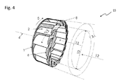
- the Fig. 4 shows a schematic perspective view of a third embodiment of the turbine runner 15.
- the buoyancy zone 3 is hereby optimized by wind deflector 8.
- This wind deflector 8 are formed by repeller-like wings on the front sides of the sliding vanes or webs 2. They should reduce disturbing turbulence in the spaces between the sliding wings 2 and shield.
- the Fig. 5 shows a schematic perspective view of an integrable in a building wall 16 turbine runner 15.
- the impeller 15 may in this case be installed in an only indicated here wall, such as. A house or building wall.
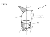
- the Fig. 6 shows a schematic perspective view of one on a building roof or other building or on flat surfaces mountable Wind turbine 30 with rotatable Windleitelement 17, which is designed as a 90 ° curved pipe socket, the outer opening 10 is horizontal and thereby deflect the wind 12 by 90 ° down towards the horizontal lying and rotating about the rotation axis 4 turbine wheel 15.
- the arranged on Windleitelement 17 flag ensures their rotation in the wind, so that the opening 10 is always directed against the wind direction 12.
- the Fig. 7 shows a schematic representation of an impinged from below impeller 15 which is mountable on a roof, which may be, for example, part of a greenhouse 25 or another building.
- the warm exhaust air 12 is directed in a horizontal direction - possibly from several sides - to the wind power plant 30 and deflected up there, so that the air can leave the impeller 15 to the side.
- FIG. 8 The schematic perspective view of Fig. 8 shows a tandem arrangement with two identical turbine wheels 15 which are coupled to a common shaft 11. Freewheels 14 can ensure that even with different flow and different wind direction 12 a same direction rotation 5 is guaranteed.
- the Fig. 9 shows a schematic representation of an alternative embodiment of a turbine runner 15, which is particularly suitable as a water turbine.
- a Coriolis turbine is formed on the basis of two truncated cones 18 and 19 connected to their base surfaces, in the lateral surfaces of which constant channels 20 are introduced in cross-section, the respective opposing channels 20 having opposite or mirror-image profiles.
- the Coriolis double cone can also be arranged with a horizontal axis in the surf area with accumulating water wave and the returning water.
- the Fig. 10 shows a schematic perspective view of a designed as a turbine blade turbine 23 water turbine, which is suitable as a so-called. Slow runner. The relatively long curved surfaces of the glides 2 make the slow flow turbine 12 seem suitable.
- the Fig. 11 shows a schematic representation of a vehicle 22 with frontally arranged turbine wheel 15 as a possible site of use of a wind turbine according to the invention 30.
- Die Fig. 12 shows a schematic representation a ship 24 with two deck mounted wind turbines 30 and turbine wheels 15 for energy conversion.
Abstract
Description
Die vorliegende Erfindung betrifft eine Windkraftanlage mit den Merkmalen des unabhängigen Anspruchs 1.The present invention relates to a wind turbine with the features of
Zur Gewinnung von elektrischer Energie aus der Wandlung von Strömungsenergie, insbesondere von Windenergie dienen sog. Windenergieanlagen, die in unterschiedlichsten Ausführungsvarianten bekannt geworden sind. Die bekannteste und für Großanlagen fast ausschließlich eingesetzte Ausführungsvariante sind auf Masten stehende, axial angeströmte und durchströmte Rotoren mit zwei oder drei Rotorblättern, deren Rotor entweder direkt oder über ein Untersetzungsgetriebe mit einem elektrischen Generator zusammenwirkt. Die Durchmesser dieser Rotoren können bei sog. Großanlagen bis zu 90 Metern oder auch mehr betragen. Daneben gibt es zahlreiche kleinere Anlagen mit geringerer Leistung, die vorwiegend für die dezentrale Energieversorgung und/oder zur Ergänzung anderer Energieträger eingesetzt werden.To obtain electrical energy from the conversion of flow energy, in particular wind energy serve so-called. Wind turbines, which have become known in various embodiments. The most well-known and almost exclusively used for large systems variant are standing on masts, axially flowed and flowed through rotors with two or three rotor blades, the rotor interacts either directly or via a reduction gear with an electric generator. The diameter of these rotors can be up to 90 meters or even more in so-called large-scale systems. In addition, there are numerous smaller plants with lower power, which are mainly used for decentralized energy supply and / or to supplement other energy sources.
Neben zahlreichen anderen Bauformen wurden in der Vergangenheit verschiedene Ausführungsvarianten von Radial-Turbinen eingesetzt. So offenbart die
Eine ähnliche Turbine zum Einsatz in Fahrzeugen, um während der Fahrt Energie zu gewinnen, ist aus der
Die
Eine kompakte Windkraftanlage, die besonders für private Nutzer geeignet sein soll, wird in der
Die
Ein Ziel der Erfindung besteht darin, ein Laufrad für eine Windkraftanlage zur Verfügung zu stellen, das axial angeströmt wird und die Luft unter rotatorischem Antrieb des Laufrades radial umlenkt, das durch eine verbesserte Gestaltung der Schaufelräder und/oder Leitflächen gegenüber bekannten einen verbesserten Wirkungsgrad aufweist.An object of the invention is to provide an impeller for a wind turbine, which is axially impinged and radially deflects the air under rotary drive of the impeller, which has an improved efficiency compared to known through an improved design of the impellers and / or guide surfaces.
Dieses Ziel der Erfindung wird mit den Gegenständen der unabhängigen Ansprüche erreicht. Weitere vorteilhafte Ausgestaltungen werden durch die Unteransprüche beschrieben. So schlägt die Erfindung zur Erreichung des genannten Ziels eine Windkraftanlage zur Wandlung von durch Luft transportierter Strömungsenergie in rotatorische mechanische und/oder elektrische Energie vor, die wenigstens ein im Wesentlichen axial angeströmtes und die Luft in annähernd radialer Richtung verlassendes Turbinenlaufrad umfasst. Dieses Turbinenlaufrad weist einen drehbar gelagerten scheibenförmigen Träger mit einer strömungslenkenden Strukturierung in Form von schräg und/oder gekrümmt verlaufenden Stegen und/oder Kanälen auf. Es ist vorgesehen, dass die Stege bzw. Kanäle jeweils über ihren Längsverlauf variable bzw. sich verändernde Querschnitte aufweisen. Die veränderlichen Querschnitte der Stege, Kanäle oder die Luft leitenden Profilierungen im Turbinenlaufrad können insbesondere einem Tragflächenprofil ähneln und eine in Strömungsrichtung zunächst zunehmende und danach abnehmende Stärke bzw. Dicke des Querschnittes aufweisen. Im vorliegenden Zusammenhang werden die Stege, die der Übertragung der Strömungsenergie des durch das Laufrad strömenden Fluides - des Windes, Wassers o. dgl. - teilweise auch als Gleitflügel bezeichnet. Die Begriffe "Stege", "Flügel", "Gleitflügel" etc. sind daher normalerweise als Synonyme zu betrachten.This object of the invention is achieved with the objects of the independent claims. Further advantageous embodiments are described by the subclaims. Thus, in order to achieve the stated aim, the invention proposes a wind power plant for converting flow energy transported by air into rotary mechanical and / or electrical energy, which comprises at least one turbine runner that flows essentially axially and leaves the air in approximately the radial direction. This turbine wheel has a rotatably mounted disk-shaped carrier with a flow-guiding structure in the form of obliquely and / or curved webs and / or channels. It is envisaged that the webs or channels each have variable or changing cross sections over their longitudinal course. The variable cross sections of the webs, channels or the air-conducting profilings in the turbine runner may in particular resemble an airfoil profile and have an initially increasing and then decreasing thickness or thickness of the cross section in the flow direction. In the present context, the webs, the transfer of the flow energy of the fluid flowing through the impeller - the wind, water o. The like. - Partially referred to as sliding vanes. The terms "webs", "wings", "glides" etc. are therefore usually to be regarded as synonyms.
Es sei in diesem Zusammenhang darauf hingewiesen, dass die gesamte Beschreibung zwar vorrangig von Windkraftanlagen und von einer Energiewandlung von Windströmung spricht, dies aber nicht einschränkend zu verstehen ist. Wann immer von einer Windkraftanlage oder von einem Turbinenlaufrad gesprochen wird, die von Luft oder einem gasförmigen Fluid angeströmt werden, so sind die Prinzipien ebenso auf flüssige Fluide und Wasserströmungen übertragbar. Der Begriff "Windkraftanlage" oder "Windturbine" ist deshalb umfassend dahingehend zu verstehen, dass damit ebenso Wasserkraftanlagen oder Wasserturbinen gemeint sein können, die nach demselben Prinzip der Strömungsumlenkung aus axialer Anströmung in radiale Abströmung funktionieren.It should be noted in this context that the entire description speaks primarily of wind turbines and an energy conversion of wind flow, but this is not to be understood as limiting. Whenever talking about a wind turbine or a turbine runner, that of air or a gaseous fluid are flown, the principles are also applicable to liquid fluids and water flows. The term "wind turbine" or "wind turbine" is therefore to be understood as meaning that it may also mean hydropower plants or water turbines which operate on the same principle of flow deflection from axial flow into radial flow.
Bei einer bevorzugten Variante der Windkraftanlage weist das Turbinenrad bzw. Turbinenlaufrad der erfindungsgemäßen Windkraftanlage eine Mehrzahl von annähernd gleichmäßig über den äußeren Bereich der stirnseitigen Oberfläche verteilten Stegen - auch als Gleitflächen oder Gleitflügel bezeichnet - auf, deren Oberflächen jeweils einen gekrümmten Verlauf aufweisen, deren Krümmung insbesondere dem vorgegebenen Kurvenverlauf einer Coriolisbeschleunigung entsprechen kann. Damit wird eine Art der Energiegewinnung aus der Strömungsenergie von Luft, Gasen und Fluiden mittels wenigstens eines Turbinenlaufrades zur Verfügung gestellt, das dem Prinzip der Coriolisbeschleunigung folgt oder zumindest ähnelt. Auf diese Weise können äußerst kompakte Windenergie- oder Wasserenergieanlagen zur Verfügung gestellt werden, die eine hohe Effektivität und eine hohe Energiedichte aufweisen. D.h., gemessen an der Größe der Windkraftanlage bzw. des Turbinenlaufrades kann damit eine hohe Energiemenge zur Verfügung gestellt werden. Die Bauart und Geometrie ermöglicht dabei einen Platz sparenden Einsatz, der bei vielen herkömmlichen Windkraftanlagen mit Propellerantrieben in dieser Form aus Platzgründen nicht möglich ist.In a preferred variant of the wind turbine, the turbine or turbine runner of the wind turbine according to the invention has a plurality of approximately uniformly distributed over the outer region of the front surface webs - also referred to as sliding surfaces or sliding - on whose surfaces each have a curved course whose curvature in particular can correspond to the predetermined curve of a Coriolis acceleration. This provides a mode of energy production from the flow energy of air, gases and fluids by means of at least one turbine impeller, which follows or at least resembles the principle of Coriolis acceleration. In this way, extremely compact wind energy or water power plants can be provided, which have a high efficiency and a high energy density. That is, measured by the size of the wind turbine or the turbine runner so that a large amount of energy can be made available. The design and geometry enables a space-saving use, which is not possible in many conventional wind turbines with propeller drives in this form for reasons of space.
Die bisher gebräuchlichen, meist nach dem Schraubenprinzip funktionierenden Repeller weisen im Wind nach Betz einen theoretischen Wirkungsgrad von 0,593 auf, der durch die Schrägstellung der Flügel und einem dem Flugzeugflügel ähnlichen Querprofil erzeugt wird, und der eine Ablenkung der Luft von unter 45 Grad beim Durchströmen bewirkt. Bei fast allen Turbinen, die nach Betz beurteilt werden können, ist die Eigenschaft des Durchströmens vorherrschend, welche zugleich voraussetzt, dass unmittelbar vor und hinter der Turbine der Raum frei sein muss, um die Funktionsfähigkeit zu gewährleisten. Bei Turbinen nach der Coriolisbeschleunigung wird der Luft - oder Wasserstrom vollständig rechtwinkelig abgelenkt und es besteht kein Raumbedarf für Luft an der Leeseite. Die sich daraus ergebenden Möglichkeiten können somit nicht nach den Betz'schen Regeln beurteilt werden.The hitherto common, usually operating on the screw principle repeller have in the wind according to Betz a theoretical efficiency of 0.593, which is produced by the inclination of the wings and a wing similar to the aircraft wing, and causes a deflection of the air of less than 45 degrees when flowing through , In almost all turbines, which can be assessed according to Betz, the characteristic of the flow prevails, which presupposes at the same time that immediately in front of and behind the turbine, the space must be free to ensure the functionality. In turbines after the Coriolis acceleration, the air or water flow is completely deflected at right angles and there is no space requirement for air on the leeward side. The resulting possibilities can not be judged according to Betz's rules.
Die Eigenschaften von Turbinen, die nach dem Coriolisprinzip arbeiten, bestehen dagegen im Wesentlichen darin, dass bei einer Zylinderturbine der frontale Windwiderstand annähernd gleich dem einer starren Wand mit annähernd gleich großer Fläche ist. Der Windwiderstand bleibt auch ungefähr gleich, unabhängig davon, ob sich die Zylinderturbine dreht oder nicht und unabhängig von ihrer Umdrehungsgeschwindigkeit. Nur im Falle einer Montage auf einem fahrenden oder schwimmenden Fahrzeug ändert sich der Druck auf die Turbine durch den Betrag der Geschwindigkeit des entsprechenden Fahrzeugs. Damit sind einerseits gewisse Segeleigenschaften angesprochen, denn die an der Unterseite nach der Corioliskurve und an der darüber liegenden stärker gekrümmten Oberseite, ähnlich dem Profil eines Flugzeugflügels, geformten Gleitflügel fangen den Wind gleichsam wie kreisförmig angeordnete Segel auf und bewirken die Drehung der Zylinderturbine. Andererseits gelten die Segeleigenschaften auch deshalb, weil ein mit einer Zylinderturbine bestücktes leichtes Fahrzeug bei entsprechender Untersetzung alleine mit der in der bewegten Luft enthaltenen Energie gegen den Wind fahren kann. In einem weiteren Schritt wird die Möglichkeit einer Rückgewinnung von Antriebsenergie bei verschiedenen Fahrzeugen als Einsparmöglichkeit von Energie genutzt. Das von einem Motorfahrzeug verdrängte Medium gibt seine durch die Fahrt entstandene Bewegungsenergie fast ausschließlich an die Umgebung (z.B. Winddruck und bewegte Pflanzen am Straßenrand) ab. Der Fahrtwind stellt aber eine vom Fahrzeug selbst verursachte Energieform dar, die man durch einen günstigen CW-Wert zu vermindern sucht, stellt aber zugleich ein Potential zur Rückgewinnung dar, das wenigstens teilweise nutzbar ist.The properties of turbines operating on the Coriolis principle, on the other hand, essentially consist in the fact that in a cylinder turbine the frontal wind resistance is approximately equal to that of a rigid wall of approximately the same size Area is. The wind resistance also remains about the same, regardless of whether the cylinder turbine is spinning or not and regardless of their rotational speed. Only in the case of mounting on a moving or floating vehicle, the pressure on the turbine changes by the amount of speed of the corresponding vehicle. Thus, on the one hand certain sailing characteristics are addressed, because at the bottom of the Coriolis curve and on the overlying more curved top, similar to the profile of an aircraft wing, molded glides capture the wind as it were like circularly arranged sails and cause the rotation of the cylinder turbine. On the other hand, the sailing characteristics also apply because a light vehicle equipped with a cylinder turbine can, with appropriate reduction, drive against the wind solely with the energy contained in the moving air. In a further step, the possibility of recovering drive energy in different vehicles is used as a savings option of energy. The displaced by a motor vehicle medium gives its resulting from the drive kinetic energy almost exclusively to the environment (eg wind pressure and moving plants on the roadside) from. However, the airstream represents an energy form caused by the vehicle itself, which one seeks to reduce by a favorable CW value, but at the same time represents a potential for recovery, which is at least partially usable.
Das Turbinenrad der erfindungsgemäßen Windkraftanlage kann wahlweise eine Mehrzahl von annähernd gleichmäßig über den äußeren Bereich der stirnseitigen Oberfläche verteilten Stegen, Gleitflächen oder -flügeln aufweisen, deren Querschnitt jeweils eine Profilierung aufweist, wobei die Oberflächen jeweils einen gekrümmten Verlauf mit unterschiedlicher Krümmung aufweisen. Grundsätzlich müssen nicht alle Stege eine identische Profilierung aufweisen, sondern können ggf. auch unterschiedlich gestaltet sein. So sind bspw. Ausführungsvarianten denkbar, bei denen nur jeder zweite Steg oder Gleitflügel eine entsprechende Profilierung aufweist, während jeder zweite Steg einen konstanten Querschnitt aufweist. Wie erwähnt, folgt die Gesamtkrümmung der Stege vorzugsweise jeweils in etwa dem Verlauf der Coriolisbeschleunigung. Da jeder Steg an seiner konvexen Außenseite eine stärkere Krümmung aufweist als an seiner konkaven Innenseite, ergibt sich eine zu den seitlichen Enden jedes Steges jeweils gegenüber dem Mittelbereich abnehmende Dicke, was den Stegen einen Querschnitt verleiht, der den Querschnitten von Flugzeugflügeln o. dgl. ähnelt. Wahlweise können die Stege des Turbinenrades jeweils hypoidförmige oder hypoidähnliche Verläufe aufweisen. Das Charakteristikum dieser Verläufe besteht darin, dass die Stege, die sich jeweils von einem kleineren Radius des Turbinenrades bis zu dessen Außenradius erstrecken, jeweils eine gleichmäßige oder nach außen hin abnehmende Krümmung aufweisen, die ungefähr einen hypoidförmigen Verlauf aufweist, so dass das Turbinenrad in einer Draufsicht einem Zahnrad mit hypiodförmiger Stirnverzahnung ähnelt.The turbine wheel of the wind power plant according to the invention can optionally have a plurality of approximately uniformly distributed over the outer region of the front surface webs, sliding surfaces or wings whose cross-section each having a profiling, wherein the surfaces each have a curved course with different curvature. In principle, not all webs must have an identical profiling, but may possibly also be designed differently. Thus, for example, embodiments are conceivable in which only every second web or sliding wing has a corresponding profiling, while each second web has a constant cross-section. As mentioned, the total curvature of the webs preferably follows approximately the course of the Coriolis acceleration. Since each web has a greater curvature on its convex outer surface than on its concave inner side, a thickness decreasing towards the lateral ends of each web relative to the central region results, giving the webs a cross section similar to the cross sections of aircraft wings or the like , Optionally, the webs of the turbine wheel may each have hypoid or hypoid-like courses. The characteristic of these curves is that the webs, each extending from a smaller radius of the turbine wheel to its outer radius, respectively have a uniform or outwardly decreasing curvature having approximately a hypoid shape, so that the turbine wheel in a plan view resembles a gear with hypiodförmiger spur toothing.
Weiterhin können die Stege des erfindungsgemäßen Turbinenlaufrades an ihren dem scheibenförmigen Träger abgewandten Stirnseiten einen oder mehrere Abweiser in Gestalt einer ringförmigen Scheibe, einzelner repellerartiger Abweiser, strömungsleitender Scheiben o. dgl. aufweisen. Darüber hinaus kann dem Turbinenrad an seinem Strömungseingang eine strömungslenkende Scheibe, ein sich verjüngender oder erweiternder Trichter o. dgl. zugeordnet sein.Furthermore, the webs of the turbine impeller according to the invention on their end faces facing away from the disc-shaped support one or more deflectors in the form of an annular disc, individual repeller-like deflector, flow-guiding discs o. The like. In addition, the turbine wheel at its flow inlet, a flow-steering disc, a tapered or widening funnel o. The like. Be assigned.
Eine vorteilhafte Ausführungsvariante der erfindungsgemäßen Windkraftanlage kann vorsehen, dass dem Turbinenrad ein strömungslenkender Kanal zugeordnet ist, der einen abschnittweise gekrümmten Verlauf aufweist. So kann der Kanal bspw. einen im Wesentlichen horizontalen Lufteinlass und einen im Wesentlichen vertikalen Luftauslass aufweisen, der am Strömungseingang des horizontal angeordneten und um eine im Wesentlichen vertikal angeordnete Achse rotierenden Turbinenrades mündet. Vorzugsweise ist dieser Kanal im Querschnitt auf den Durchmesser des Turbinenrades abgestimmt und weist ggf. eine Leiteinrichtung zur Drehung gegen die Windrichtung auf, so dass die Kanalmündung immer in den Wind gerichtet bleiben kann.An advantageous embodiment of the wind turbine according to the invention can provide that the turbine wheel is assigned a flow-directing channel, which has a sectionally curved course. For example, the channel may have a substantially horizontal air inlet and a substantially vertical air outlet which opens at the flow inlet of the turbine wheel arranged horizontally and rotating about a substantially vertically arranged axis. Preferably, this channel is tuned in cross-section to the diameter of the turbine wheel and optionally has a guide for rotation against the wind direction, so that the channel mouth can always remain directed in the wind.
Eine weitere Variante der Windkraftanlage kann vorsehen, dass das horizontal auf einem Gebäude angeordnete und um eine im Wesentlichen vertikal angeordnete Achse rotierende Turbinenrad von unten angeströmt ist, wobei Luftkanäle warme Abluft des Gebäudes zum Turbinenrad leiten.A further variant of the wind power plant can provide that the turbine wheel, which is arranged horizontally on a building and rotates about an essentially vertically arranged axis, flows from below, wherein air ducts conduct warm exhaust air from the building to the turbine wheel.
Eine mobile Windkraftanlage kann vorsehen, dass wenigstens ein im Wesentlichen vertikal angeordnetes und um eine im Wesentlichen horizontal angeordnete Achse rotierendes Turbinenrad an einem Land-, Wasser- oder Luftfahrzeug montiert und vom Fahrtwind und/oder von Luftströmungen angeströmt ist.A mobile wind power plant can provide that at least one substantially vertically arranged and about a substantially horizontally disposed axis rotating turbine wheel mounted on a land, water or aircraft and is flowed by the wind and / or air currents.
Wie oben erwähnt, umfasst die Erfindung nicht nur die Windkraftanlage selbst, sondern auch das rotierende, von Luft in axialer Richtung angeströmte Turbinenrad oder Turbinenlaufrad einer solchen Windkraftanlage gemäß einer der zuvor beschriebenen Ausführungsvarianten. Zudem umfasst die Erfindung auch ein solches Turbinenrad, das gemäß einer der zuvor beschriebenen Ausführungsvarianten aufgebaut ist und von Wasser angeströmt ist, um die kinetische Energie des Wassers in mechanische Rotationsenergie und/oder in elektrische Energie zu wandeln.As mentioned above, the invention comprises not only the wind turbine itself, but also the rotating turbine wheel or turbine runner of air flowed in the axial direction of such a wind turbine according to one of the previously described embodiments. In addition, the invention also includes such a turbine wheel, which is constructed according to one of the previously described embodiments and has been supplied with water in order to convert the kinetic energy of the water into mechanical rotational energy and / or into electrical energy.
Nachfolgend werden nochmals einige Aspekte und weitere Varianten der vorliegenden Erfindung beschrieben. So betrifft die vorliegende Erfindung nicht nur eine Wind- oder Wasserkraftanlage und das für die Energiewandlung erforderliche Turbinenrad, sondern auch ein Verfahren zur Energiegewinnung aus bewegten Flüssigkeiten und Gasen mit Turbinen nach dem Prinzip der Coriolisbeschleunigung, das dadurch gekennzeichnet, ist, dass die strömenden Flüssigkeiten oder Gase axial auf einen runden und scheibenförmigen Träger treffen, auf dem, durch stegartige Erhöhungen, genannt Gleitflügel, oder rillenartige Vertiefungen, genannt Gleitkanäle, die durch die Corioliskraft entstehende Kurve vorgegeben ist, so dass das jeweilige Medium in der Summe radial und rechtwinkelig nach außen drängt und dadurch den Träger tangential in der durch die Kurve bestimmten Richtung beschleunigt. Dieses genannte Prinzip beruht auf einer drehenden Scheibe, auf der ein Körper eine nach außen gerichtete Zentrifugalkraft erfährt. Dabei wird die von der Corioliskraft beschriebene Kurve vorgegeben, die beim axialen Auftreffen eines Mediums ihrerseits die Scheibe in Drehung versetzt.Hereinafter some aspects and further variants of the present invention will be described. Thus, the present invention relates not only to a wind turbine or hydropower plant and the turbine wheel required for the energy conversion, but also to a method for generating energy from moving fluids and gases with turbines on the principle of Coriolis acceleration, which is characterized in that the flowing liquids or Gases axially on a round and disc-shaped support meet, on which, by web-like elevations, called sliding vanes, or groove-like depressions, called sliding channels, which is given by the Coriolis force curve, so that the respective medium in the sum radially and perpendicular expels to the outside and thereby accelerates the carrier tangentially in the direction determined by the curve. This principle is based on a rotating disk on which a body experiences an outward centrifugal force. In this case, the curve described by the Coriolis force is given, which in turn causes the disc in the axial impact of a medium in rotation.
Das Verfahren zur Energiegewinnung bzw. Energiewandlung verwendet eine sog. Zylinder-Turbine mit Gleitflügelprofilen, die die Corioliskraft mit dem Bernoulli-Effekt kombinieren. Diese Turbine wird axial angeströmt, wobei die Anströmung auf einen winddichten Träger erfolgt, auf dem sich axial angebrachte Gleitflügel mit einem dem Flugzeugflügel ähnlichen Querprofil befinden, die an der Unterseite nach der Kurve der Coriolisbeschleunigung gekrümmt sind und an der darüber liegenden Oberseite stärker gekrümmt wird. Die in der Drehrichtung vorne liegende Profilseite ist, abweichend vom Flugzeugflügelprofil, als eine den Luftstrom trennende Kante ausgebildet, die in der Summe den Luftstrom rechtwinkelig ablenkt und so auf den Träger um die Drehachse eine Drehung verursachen. Die vorgegebene Kurve, die ungefähr dem Verlauf einer Coriolisbeschleunigung entspricht, bewirkt an der Unterseite der Gleitflügel deren Drehung und Ablenkung und damit eine Drehung des Trägers. Das Querprofil mit der an der Oberseite stärkeren Krümmung verstärkt nach dem Bernoulli-Effekt den Auftrieb und liefert somit eine Drehbeschleunigung der Scheibe des Turbinenrades.The process for energy production or energy conversion uses a so-called cylinder turbine with Gleitflügelprofilen that combine the Coriolis force with the Bernoulli effect. This turbine is flowed axially, wherein the flow takes place on a windproof carrier on which are axially mounted sliding wings with a wing profile similar to the aircraft wing, which are curved at the bottom of the Coriolis acceleration curve and is more curved on the overlying top. The profile side lying in front in the direction of rotation is, deviating from the aircraft wing profile, formed as an edge separating the air flow, the sum of which deflects the air flow at right angles and thus cause rotation on the support about the axis of rotation. The predetermined curve, which corresponds approximately to the course of a Coriolis acceleration, causes on the underside of the sliding wings their rotation and deflection and thus a rotation of the carrier. The transverse profile with the curvature stronger at the top reinforces the buoyancy according to the Bernoulli effect and thus provides a rotational acceleration of the disc of the turbine wheel.
An der Zylinder-Turbine können im Bereich der Auftriebszone die Räume zwischen den Gleitflügeln mit Windabweisern gegen die axial auftreffende Anströmung derart abgeschirmt sein, dass der zwischen den Gleitflügeln austretende Luftstrom nicht beeinflusst wird und zugleich, durch die Schrägstellung der Windabweiser in der Drehrichtung, die Zylinder-Turbine einen zusätzlichen Drehimpuls erfährt. Diese Variante der Zylinderturbine sieht vor, dass auch die Auftriebszone durch Windabweiser zur Optimierung des Systems beitragen kann, indem die Abweiser repellerartig ausgebildet und angebracht sein können und gleichzeitig störende Turbulenzen in den Räumen zwischen den Gleitflügeln abschirmen können.In the area of the buoyancy zone, the spaces between the glide wings with wind deflectors against the axially impinging flow can be shielded on the cylinder turbine such that the air flow exiting between the glides is not influenced and at the same time, due to the oblique position of the wind deflectors in the direction of rotation, the cylinders Turbine experiences an additional angular momentum. This variant of the cylinder turbine provides that also the buoyancy zone by wind deflector for Optimization of the system can help by the deflectors are repeller-like design and can be installed while shielding disturbing turbulence in the spaces between the sliding wings.
Weiterhin kann die Umgebung der Zylinder-Turbine einschließlich der Auftriebszone von einer Gebäudewand oder anderen Bauteilen abgedeckt sein, wobei sich darin eine Öffnung befinden kann, die genau vor dem Innendurchmesser liegt. Diese Möglichkeit sieht einen Einbau der Turbine in Gebäudewänden oder anderen festen Wandflächen oder Gebäudefassaden oder in sonstigen geeigneten Flächen oder Stellen vor. Die Wand kann die Auftriebszone abschirmen, trägt jedoch insgesamt kaum zur Optimierung bei.Furthermore, the environment of the cylinder turbine including the buoyancy zone can be covered by a building wall or other components, wherein it can be located in an opening which lies just in front of the inner diameter. This possibility provides for the installation of the turbine in building walls or other solid wall surfaces or building facades or in other suitable areas or places. The wall can shield the buoyancy zone, but overall hardly contributes to the optimization.
Bei einer weiteren Ausführungsvariante der Vorrichtung kann die Zylinder-Turbine mit ihrer Achse senkrecht zur Windrichtung aufgestellt sein, wobei sich über der Öffnung ein kreisförmig drehbarer Windfang befinden kann, der mit seiner Windfahne selbständig seine Öffnung in den Wind dreht und ihn dabei in die Zylinder-Turbine umlenkt. Ein solches drehbares windfangartiges Rohr kann bspw. auch horizontal, also mit senkrechter Drehachse, z.B. auf Dächern von Gebäuden oder auf anderen geeigneten Flächen betrieben werden.In a further embodiment variant of the device, the cylinder turbine can be set up with its axis perpendicular to the wind direction, wherein a circularly rotatable windscreen can be located above the opening, which independently turns its opening into the wind with its wind vane and thereby moves it into the cylinder. Turbine deflects. Such a rotatable wind-catching pipe can, for example, also horizontal, ie with a vertical axis of rotation, e.g. be operated on roofs of buildings or on other suitable surfaces.
Wahlweise kann die Zylinder-Turbine mit ihrer Achse senkrecht mit ihrer Öffnung zur Erde aufgestellt werden, um einen erwärmten Luftstrom, der aus verschiedenen Ursachen entsteht und mit Folien oder Dächern abgegrenzt wird, in die Öffnung zu leiten. Damit ist eine Möglichkeit gegeben, an der höchsten Stelle eines Treibhauses oder eines anderen warme Abluft erzeugenden Gebäudes ein Turbinenlaufrad anzubringen, ohne dass Verluste durch Umsetzung von Wärme in Bewegungsenergie in einem Kamin entstehen.Optionally, the cylinder turbine can be placed with its axis perpendicular with its opening to the earth, in order to direct a heated air flow, which arises from different causes and is delimited with films or roofs, in the opening. Thus, a possibility is given to install a turbine runner at the highest point of a greenhouse or another warm air-generating building, without losses resulting from the conversion of heat into kinetic energy in a fireplace.
Eine weitere Möglichkeit besteht darin, eine Doppel-Zylinder-Turbine zu bilden, bei der zwei gleiche oder unterschiedliche - d.h. insbesondere gleich oder unterschiedlich dimensioniere - Zylinder-Turbinen, die gegensätzliche Drehrichtungen aufweisen, zu kombinieren, indem sie mit ihren Öffnungen entgegengesetzt mit jeweils einem Freilauf fest verbunden sind, der drehfest entgegen der Drehrichtung auf einer Welle sitzt und nur eine Drehrichtung der Welle zulässt, so dass bei oszillierenden Strömungen die Luvseite die Leeseite nicht mitschleppt. Bei dieser Variante werden zwei Laufräder in einer Weise kombiniert, dass sie mit ihren Trägern aneinander grenzen oder auch voneinander beabstandet in fluchtender Anordnung mit einer gemeinsamen Welle gekoppelt sind, so dass ihre Öffnungen gegenüber liegen bzw. voneinander abgewandt sind. Diese Kombination ermöglicht es, oszillierende oder ungleichmäßige oder wechselnde Strömungen aus verschiedenen Richtungen in eine gleiche Drehung auf eine Welle zu übertragen. Zur Optimierung kann ein Freilauf auf der Welle eingebaut werden, so dass eine feste Drehrichtung gegeben ist, auch wenn einer der Rotoren in eine entgegengesetzte Richtung dreht.Another possibility is to form a double-cylinder turbine, in which two identical or different - ie in particular equal or different dimension - cylinder turbines having opposite directions of rotation to combine, by opposing their openings with one Freewheel are firmly connected, the rotationally fixed against the direction of rotation sits on a shaft and allows only one direction of rotation of the shaft, so that with oscillating currents, the windward side of the leeward side not entrains. In this variant, two wheels are combined in such a way that they adjoin one another with their carriers or are also spaced from one another in an aligned arrangement with a common shaft, so that their openings are opposite or facing away from each other. These Combination makes it possible to transmit oscillating or non-uniform or alternating flows from different directions in the same rotation to a shaft. To optimize a freewheel can be installed on the shaft, so that a fixed direction of rotation is given, even if one of the rotors rotates in an opposite direction.
Eine von den zuvor beschriebenen Varianten und Gestaltungen deutlich abweichende Ausführungsvariante des Turbinenrades kann einen sog. Coriolis-DoppelKegel vorsehen, der vorwiegend zur Wandlung von Strömungsenergie des Wassers geeignet ist. Hierbei sind in die Mantelfläche von zwei gleich großen Kegelstümpfen, die mit einer gemeinsamen Grundfläche fest verbunden sind, rillenartige Vertiefungen, im Querschnitt gleiche Gleitkanäle, eingebracht, die der Kurve der Coriolisbeschleunigung folgen, wobei spiegelbildlich auf dem gegenüber liegenden Kegelstumpf die gleichen Gleitkanäle komplementär eingebracht sind, mit dem Zweck, bei oszillierenden Strömungen und Wellen eine gleichartige Drehung zu erzielen. Eine solche Coriolisturbine auf der Grundlage von zwei mit ihren Grundflächen verbundenen Kegelstümpfen, auf deren Mantelflächen im Querschnitt gleich bleibende Kanäle eingebracht sind, wobei die jeweils gegenüber liegenden Kanäle entgegengesetzten oder spiegelbildlichen Kurven folgen, dient vorzugsweise der Wandlung von Strömungsenergie fließenden Wassers in rotatorische Bewegungsenergie bzw. in mechanische Energie, die ggf. in elektrische Energie gewandelt werden kann. Bei axial fester Positionierung mit senkrechter Achse zum Wasserspiegel erzeugt der Doppelkegel sowohl bei aufschwingender wie auch bei abschwingender Wasserwelle eine gleichsinnige Drehung. Der Coriolis-Doppelkegel kann auch mit horizontaler Achse in einem Brandungsbereich in Ufernähe mit auflaufender Wasserwelle und dem zurückfliegenden Wasser jeweils in gleichsinnige Drehung versetzt werden.A variant of the turbine wheel which deviates significantly from the variants and designs described above can provide a so-called Coriolis double cone, which is predominantly suitable for converting the flow energy of the water. Here are in the lateral surface of two equal truncated cones, which are firmly connected to a common base, groove-like recesses, in cross-section equal sliding channels introduced, which follow the curve of the Coriolis acceleration, wherein the same sliding channels are introduced in mirror image on the opposite truncated cone complementary , with the purpose to achieve a similar rotation in oscillating flows and waves. Such a Coriolis turbine on the basis of two connected with their bases truncated cones, on the lateral surfaces in the same cross-section channels are introduced, the opposite channels follow opposite or mirror-image curves, preferably serves the conversion of flow energy flowing water into rotational kinetic energy or into mechanical energy, which can be converted into electrical energy if necessary. In the case of axially fixed positioning with a vertical axis to the water level, the double cone produces a rotation in the same direction both when the water wave is swinging upwards and downwards. The Coriolis double cone can also be placed in the same direction with a horizontal axis in a surf area near the shore with rising water wave and the returning water.
Weiterhin kann das Turbinenrad auch als sog. Coriolis-Schaufel-Turbine ausgebildet sein, die sich ebenfalls vorwiegend für Wasser als strömendes Medium eignet, dessen Energie in rotatorische Bewegungsenergie gewandelt wird. Bei einem solchen Turbinenrad sind Gleitflächen vorhanden, die mit dem Träger rechtwinkelig fest verbunden sind und die jeweils den Corioliskurven folgen. Die Gleitflächen, welche die Drehrichtung bestimmen, sind parallel zur Drehachse angeordnet und sind bis nahe an die Welle gezogen, um die Zulauföffnung möglichst auf den Durchmesser der Welle zu vermindern, wobei die axiale Höhe der Gleitflächen vom Zentrum zur Peripherie abnehmen oder zunehmen kann. Eine solche Coriolis-Schaufel-Turbine mit gekrümmten Gleitflächen eignet sich besonders zum Einsatz in langsam fließenden Gewässern, wobei gleichzeitig ein örtlich begrenzter Stau erzeugt wird, der zum Antrieb des Turbinenrades genutzt wird.Furthermore, the turbine wheel can also be designed as a so-called. Coriolis blade turbine, which is also mainly suitable for water as a flowing medium whose energy is converted into rotational kinetic energy. In such a turbine wheel sliding surfaces are present, which are connected at right angles to the carrier and each follow the Coriolis curves. The sliding surfaces, which determine the direction of rotation are arranged parallel to the axis of rotation and are pulled close to the shaft to reduce the inlet opening as possible to the diameter of the shaft, wherein the axial height of the sliding surfaces from the center to the periphery decrease or increase. Such a Coriolis blade turbine with curved sliding surfaces is particularly suitable for use in slow-flowing waters, wherein at the same time a localized congestion is generated, which is used to drive the turbine wheel.
Nahezu alle der zuvor beschriebenen Ausführungsvarianten der Turbinen eignen sich auch zur Kombination miteinander, wobei die jeweiligen Turbinen einzeln, doppelt mit Freilauf, oder doppelt mit fester Verbindung betrieben werden können.Almost all of the previously described embodiments of the turbines are also suitable for combination with each other, wherein the respective turbines can be operated individually, double with freewheel, or double with a fixed connection.
Die Erfindung ermöglicht darüber hinaus auch die Rückgewinnung von Antriebsenergie aus von Fahrzeugen verursachtem Fahrtwind mit Turbinen gemäß einer der zuvor beschriebenen Varianten. Hierbei können auf Fahrzeugen und/oder Schiffen die beanspruchten Turbinen an Stellen angebracht werden, die ohnehin hohem Winddruck ausgesetzt sind, um den durch die Fahrt entstehenden Wind energetisch teilweise zurück zu gewinnen, oder auf Schiffen durch in alle Richtungen schwenkbare Turbinen den Wind energetisch zu nutzen und die winddichte Trägerfläche bei bestimmten Verhältnissen wie ein Segel zu benutzen. Die praktische Anwendung der Energiewandlung bei sich bewegenden und/oder dem Wind ausgesetzten Fahrzeugen und Schiffen ist deshalb möglich, wie die Strömung rechtwinkelig abgelenkt wird und somit der Raum an der Leeseite des Turbinenrades dem Fahrzeug bereit gestellt wird.The invention also makes it possible to recover drive energy from vehicle wind induced wind with turbines according to one of the variants described above. Here, the claimed turbines can be mounted on vehicles and / or ships in places that are already exposed to high wind pressure to recover the energy generated by the wind energy partially back, or to use the energy of the wind on ships by swiveling in all directions the wind and to use the windproof support surface in certain conditions like a sail. The practical application of the energy conversion in moving and / or wind-exposed vehicles and ships is therefore possible, as the flow is deflected at right angles and thus the space on the lee side of the turbine wheel is provided to the vehicle.
Im Folgenden sollen Ausführungsbeispiele die Erfindung und ihre Vorteile anhand der beigefügten Figuren näher erläutern. Die Größenverhältnisse der einzelnen Elemente zueinander in den Figuren entsprechen nicht immer den realen Größenverhältnissen, da einige Formen vereinfacht und andere Formen zur besseren Veranschaulichung vergrößert im Verhältnis zu anderen Elementen dargestellt sind.
-
Fig. 1 zeigt eine schematische Perspektivdarstellung einer Ausführungsvariante eines Turbinenlaufrades einer erfindungsgemäßen Windkraftanlage. -
Fig. 2 zeigt einen Detaillängsschnitt eines Abschnittes des Turbinenlaufrades gemäßFig. 1 . -
Fig. 3 zeigt eine schematische Perspektivdarstellung einer weiteren Ausführungsvariante des Turbinenlaufrades. -
Fig. 4 zeigt eine schematische Perspektivdarstellung einer dritten Ausführungsvariante des Turbinenlaufrades. -
Fig. 5 zeigt eine schematische Perspektivdarstellung eines in einer Gebäudewand integrierbaren Turbinenlaufrades. -
Fig. 6 zeigt eine schematische Perspektivdarstellung einer auf einem Gebäudedach oder anderem Bauwerk bzw. auf ebenen Flächen montierbaren Windkraftanlage mit drehbarem Windleitelement. -
Fig. 7 zeigt eine schematische Darstellung eines von unten angeströmten Laufrades, das auf einem Dach montierbar ist. -
Fig. 8 zeigt eine Tandemanordnung mit zwei gleichartigen Turbinenlaufrädern, die mit einer gemeinsamen Welle gekoppelt sind, in schematischer Darstellung. -
Fig. 9 zeigt eine schematische Darstellung einer alternativen Ausführungsvariante eines Turbinenlaufrades, das sich insbesondere als Wasserturbine eignet. -
Fig. 10 zeigt eine schematische Perspektivansicht einer Wasserturbine, die sich als Langsamläufer eignet. -
Fig. 11 zeigt eine schematische Darstellung eines Fahrzeuges mit frontseitig angeordnetem Turbinenlaufrad. -
Fig. 12 zeigt eine schematische Darstellung eines Schiffes mit zwei deckseitig montierten Windkraftanlagen zur Energiewandlung.
-
Fig. 1 shows a schematic perspective view of an embodiment of a turbine runner of a wind turbine according to the invention. -
Fig. 2 shows a detail section of a portion of the turbine runner according toFig. 1 , -
Fig. 3 shows a schematic perspective view of another embodiment of the turbine runner. -
Fig. 4 shows a schematic perspective view of a third embodiment of the turbine runner. -
Fig. 5 shows a schematic perspective view of an integrable in a building wall turbine runner. -
Fig. 6 shows a schematic perspective view of a mountable on a building roof or other structure or on flat surfaces wind turbine with rotatable wind deflector. -
Fig. 7 shows a schematic representation of an impinged from below impeller, which is mounted on a roof. -
Fig. 8 shows a tandem arrangement with two identical turbine wheels, which are coupled to a common shaft, in a schematic representation. -
Fig. 9 shows a schematic representation of an alternative embodiment of a turbine runner, which is particularly suitable as a water turbine. -
Fig. 10 shows a schematic perspective view of a water turbine, which is suitable as a slow-speed. -
Fig. 11 shows a schematic representation of a vehicle with front-mounted turbine runner. -
Fig. 12 shows a schematic representation of a ship with two deck mounted wind turbines for energy conversion.
Für gleiche oder gleich wirkende Elemente der Erfindung werden identische Bezugszeichen verwendet. Ferner werden der Übersicht halber nur Bezugszeichen in den einzelnen Figuren dargestellt, die für die Beschreibung der jeweiligen Figur erforderlich sind. Die dargestellten Ausführungsformen stellen lediglich Beispiele dar, wie die erfindungsgemäße Vorrichtung oder das erfindungsgemäße Verfahren ausgestaltet sein können und stellen keine abschließende Begrenzung dar.For identical or equivalent elements of the invention, identical reference numerals are used. Furthermore, for the sake of clarity, only reference symbols are shown in the individual figures, which are required for the description of the respective figure. The illustrated embodiments are merely examples of how the device or method of the invention may be configured and are not an exhaustive limitation.
Die schematische Darstellung der
Die schematische Darstellung der
Die
Die
Die
Die
Die schematische Perspektivdarstellung der
Die
Die
Die
Die Erfindung wurde unter Bezugnahme auf eine bevorzugte Ausführungsform beschrieben. Es ist jedoch für einen Fachmann vorstellbar, dass Abwandlungen oder Änderungen der Erfindung gemacht werden können, ohne dabei den Schutzbereich der nachstehenden Ansprüche zu verlassen.The invention has been described with reference to a preferred embodiment. However, it will be apparent to those skilled in the art that modifications or changes may be made to the invention without departing from the scope of the following claims.
- 11
- Trägercarrier
- 22
- Gleitflügel, StegSliding wing, dock
- 33
- Auftriebszoneupwelling
- 44
- Drehachseaxis of rotation
- 55
- Drehrichtungdirection of rotation
- 66
- Radius (nicht belegt)Radius (not assigned)
- 77
- Zentriwinkel (nicht belegt)Central angle (not occupied)
- 88th
- Windabweiserwind deflector
- 99
- axiale Höheaxial height
- 1010
- Innendurchmesser, ÖffnungInner diameter, opening
- 1111
- Wellewave
- 1212
- Strömungsrichtung, FahrtwindFlow direction, wind
- 1313
- Leitwerk (nicht belegt)Tail unit (not occupied)
- 1414
- Freilauffreewheel
- 1515
- Zylinder-TurbineCylinder turbine
- 1616
- Wandwall
- 1717
- Windfang mit -fahneWindscreen with banner
- 1818
- linker Kegelstumpfleft truncated cone
- 1919
- rechter Kegelstumpfright truncated cone
- 2020
- Gleitkanalsliding channel
- 2121
- Querprofilcross Section
- 2222
- Fahrzeugvehicle
- 2323
- Schaufel-TurbineBlade turbine
- 2424
- Schiffship
- 2525
- Treibhausgreenhouse
- 3030
- WindkraftanlageWind turbine
Claims (14)
Applications Claiming Priority (1)
| Application Number | Priority Date | Filing Date | Title |
|---|---|---|---|
| DE102011107071A DE102011107071A1 (en) | 2011-07-11 | 2011-07-11 | Process for recovering energy from moving liquids and gases with turbines according to the principle of Coriolis acceleration |
Publications (2)
| Publication Number | Publication Date |
|---|---|
| EP2546513A2 true EP2546513A2 (en) | 2013-01-16 |
| EP2546513A3 EP2546513A3 (en) | 2015-06-03 |
Family
ID=46581752
Family Applications (1)
| Application Number | Title | Priority Date | Filing Date |
|---|---|---|---|
| EP12175942.7A Withdrawn EP2546513A3 (en) | 2011-07-11 | 2012-07-11 | Wind farm assembly and turbine therefor |
Country Status (2)
| Country | Link |
|---|---|
| EP (1) | EP2546513A3 (en) |
| DE (2) | DE102011107071A1 (en) |
Cited By (2)
| Publication number | Priority date | Publication date | Assignee | Title |
|---|---|---|---|---|
| DE202014103036U1 (en) | 2014-07-02 | 2014-07-15 | Elmar Ph. Putz | Exhaust gas turbocharger of an internal combustion engine |
| DE202015003302U1 (en) | 2015-05-05 | 2015-06-11 | Elmar Ph. Putz | Round hollow body for catching wind from all horizontal directions -Round- |
Families Citing this family (2)
| Publication number | Priority date | Publication date | Assignee | Title |
|---|---|---|---|---|
| DE102016011685B4 (en) | 2016-09-29 | 2021-01-07 | Hans Mathea | Wind turbine |
| RU207267U1 (en) * | 2021-06-10 | 2021-10-21 | Роман Ефимович Либерзон | WIND UNIT |
Citations (5)
| Publication number | Priority date | Publication date | Assignee | Title |
|---|---|---|---|---|
| DE3418946A1 (en) | 1984-05-22 | 1985-11-28 | Elmar Dipl.-Ing. Putz (FH), 8380 Landau | Radial-flow reaction turbine |
| DE102005049794A1 (en) | 2005-10-18 | 2007-04-19 | Eew Maschinenbau Gmbh | Propeller for use in e.g. aircraft, has guiding structures arranged at propeller blades and protruding from surface of blades, where structures are connected with one another and extend in intermediate space between blades |
| DE102008025719A1 (en) | 2008-05-29 | 2009-12-03 | Klaus Fichtner | Wind turbine |
| DE202009013425U1 (en) | 2009-10-06 | 2009-12-17 | Putz, Elmar, Dipl.-Ing. (FH) | Cylinder turbine for the recovery of drive energy |
| DE102008046209A1 (en) | 2008-09-08 | 2010-03-11 | Moser, Karl, Dipl.-Ing. (TU) | Turbine wheel for gaseous media, comprises impeller which is arranged in circular housing, where entrance angle is greater than ten degree and less than ninety degree, where exit angle is less than ninety degree |
Family Cites Families (10)
| Publication number | Priority date | Publication date | Assignee | Title |
|---|---|---|---|---|
| CA1266005A (en) * | 1984-02-07 | 1990-02-20 | Louis Obidniak | Wind turbine "runner" impulse type |
| US5221186A (en) * | 1991-10-23 | 1993-06-22 | Machin Thomas H | Wind turbine apparatus with fluidic rotation indicator |
| WO2002057625A1 (en) * | 2001-01-17 | 2002-07-25 | Smith J C | A wind-driven electrical power-generating device |
| DE20308468U1 (en) * | 2003-05-30 | 2003-08-28 | Wu Shiang Huei | Internal combustion engine/electric motor hybrid vehicle with complex generators has e.g. turbogenerators beneath engine compartment cover opening and above chassis opening |
| CA2467199A1 (en) * | 2004-05-19 | 2005-11-19 | Bud T.J. Johnson | Wind turbine |
| US7452187B2 (en) * | 2005-08-09 | 2008-11-18 | Praxair Technology, Inc. | Compressor with large diameter shrouded three dimensional impeller |
| CA2620880A1 (en) * | 2005-08-22 | 2007-04-19 | Viryd Technologies Inc. | Fluid energy converter |
| DE202007010614U1 (en) * | 2007-07-27 | 2007-10-18 | Dohm, Rudolf | Wind turbine with a shroud of the turbine blades and with the use of devices for generating rotational flows behind the plant |
| JP4396775B2 (en) * | 2007-11-26 | 2010-01-13 | ダイキン工業株式会社 | Centrifugal fan |
| JP4778989B2 (en) * | 2008-07-04 | 2011-09-21 | 栄作 真野 | Vehicle travel support device |
-
2011
- 2011-07-11 DE DE102011107071A patent/DE102011107071A1/en not_active Withdrawn
-
2012
- 2012-07-11 DE DE202012013307.1U patent/DE202012013307U1/en not_active Expired - Lifetime
- 2012-07-11 EP EP12175942.7A patent/EP2546513A3/en not_active Withdrawn
Patent Citations (5)
| Publication number | Priority date | Publication date | Assignee | Title |
|---|---|---|---|---|
| DE3418946A1 (en) | 1984-05-22 | 1985-11-28 | Elmar Dipl.-Ing. Putz (FH), 8380 Landau | Radial-flow reaction turbine |
| DE102005049794A1 (en) | 2005-10-18 | 2007-04-19 | Eew Maschinenbau Gmbh | Propeller for use in e.g. aircraft, has guiding structures arranged at propeller blades and protruding from surface of blades, where structures are connected with one another and extend in intermediate space between blades |
| DE102008025719A1 (en) | 2008-05-29 | 2009-12-03 | Klaus Fichtner | Wind turbine |
| DE102008046209A1 (en) | 2008-09-08 | 2010-03-11 | Moser, Karl, Dipl.-Ing. (TU) | Turbine wheel for gaseous media, comprises impeller which is arranged in circular housing, where entrance angle is greater than ten degree and less than ninety degree, where exit angle is less than ninety degree |
| DE202009013425U1 (en) | 2009-10-06 | 2009-12-17 | Putz, Elmar, Dipl.-Ing. (FH) | Cylinder turbine for the recovery of drive energy |
Cited By (3)
| Publication number | Priority date | Publication date | Assignee | Title |
|---|---|---|---|---|
| DE202014103036U1 (en) | 2014-07-02 | 2014-07-15 | Elmar Ph. Putz | Exhaust gas turbocharger of an internal combustion engine |
| DE102015110411A1 (en) | 2014-07-02 | 2016-01-07 | Elmar Ph. Putz | Exhaust gas turbocharger of an internal combustion engine |
| DE202015003302U1 (en) | 2015-05-05 | 2015-06-11 | Elmar Ph. Putz | Round hollow body for catching wind from all horizontal directions -Round- |
Also Published As
| Publication number | Publication date |
|---|---|
| EP2546513A3 (en) | 2015-06-03 |
| DE102011107071A1 (en) | 2013-01-17 |
| DE202012013307U1 (en) | 2016-02-19 |
Similar Documents
| Publication | Publication Date | Title |
|---|---|---|
| EP2798205B1 (en) | Turbomachine | |
| WO2009021485A2 (en) | Flow energy installation | |
| DE19920560A1 (en) | Wind power plant with vertical rotor | |
| DE102011016141B4 (en) | Wind turbine with a nozzle body | |
| WO2008052713A1 (en) | Wind power installation, generator for generation of electrical power from ambient air, and method for generation of electrical power from ambient air in motion | |
| EP2469078B1 (en) | Wind energy hybrid rotor | |
| DE202008010396U1 (en) | Flow energy installation | |
| EP2594784A2 (en) | Vertical wind turbine and rotor blade for the same | |
| EP2395235A2 (en) | Wind turbine with a drop shaped housing | |
| DE202008010395U1 (en) | Flow energy installation | |
| EP2128432B1 (en) | Wind turbine assembly with axial air intake and radial air outlet | |
| EP2546513A2 (en) | Wind farm assembly and turbine therefor | |
| DE202013011686U1 (en) | Combined wind turbine | |
| DE3315439C2 (en) | ||
| DE102008036307A1 (en) | Versatile wind energy conversion unit for static and mobile applications, has roller-type rotor carrying main blades and deflector blades, operating in diffuser casing | |
| WO2013171320A1 (en) | Wind motor with rotational axis substantially perpendicular to the wind direction | |
| DE102016007054A1 (en) | FLOW CONVERTER WITH A FLOW PIPE | |
| WO2008028675A2 (en) | Wind power installation | |
| DE102009015669A1 (en) | Small wind turbine | |
| DE112017004377B4 (en) | wind turbine plant | |
| DE2444803A1 (en) | Wind or river driven turbine - has rotor with blades having tangential inlets and shaped casing | |
| AT523104B1 (en) | Support structure with diffuser for Savonius turbine rotor | |
| DE102016112876A1 (en) | Durchströmwindkraftanlage | |
| DE202010009987U1 (en) | Turbine III | |
| EP2602479A1 (en) | Combination wind power assembly |
Legal Events
| Date | Code | Title | Description |
|---|---|---|---|
| PUAI | Public reference made under article 153(3) epc to a published international application that has entered the european phase |
Free format text: ORIGINAL CODE: 0009012 |
|
| AK | Designated contracting states |
Kind code of ref document: A2 Designated state(s): AL AT BE BG CH CY CZ DE DK EE ES FI FR GB GR HR HU IE IS IT LI LT LU LV MC MK MT NL NO PL PT RO RS SE SI SK SM TR |
|
| AX | Request for extension of the european patent |
Extension state: BA ME |
|
| PUAL | Search report despatched |
Free format text: ORIGINAL CODE: 0009013 |
|
| AK | Designated contracting states |
Kind code of ref document: A3 Designated state(s): AL AT BE BG CH CY CZ DE DK EE ES FI FR GB GR HR HU IE IS IT LI LT LU LV MC MK MT NL NO PL PT RO RS SE SI SK SM TR |
|
| AX | Request for extension of the european patent |
Extension state: BA ME |
|
| RIC1 | Information provided on ipc code assigned before grant |
Ipc: F03D 1/06 20060101AFI20150429BHEP |
|
| STAA | Information on the status of an ep patent application or granted ep patent |
Free format text: STATUS: THE APPLICATION IS DEEMED TO BE WITHDRAWN |
|
| 18D | Application deemed to be withdrawn |
Effective date: 20151204 |