EP2546495A1 - System of treating exhaust gas of engine - Google Patents
System of treating exhaust gas of engine Download PDFInfo
- Publication number
- EP2546495A1 EP2546495A1 EP11753250A EP11753250A EP2546495A1 EP 2546495 A1 EP2546495 A1 EP 2546495A1 EP 11753250 A EP11753250 A EP 11753250A EP 11753250 A EP11753250 A EP 11753250A EP 2546495 A1 EP2546495 A1 EP 2546495A1
- Authority
- EP
- European Patent Office
- Prior art keywords
- opening
- change rate
- throttle valve
- regeneration
- exhaust
- Prior art date
- Legal status (The legal status is an assumption and is not a legal conclusion. Google has not performed a legal analysis and makes no representation as to the accuracy of the status listed.)
- Ceased
Links
Images


Classifications
-
- F—MECHANICAL ENGINEERING; LIGHTING; HEATING; WEAPONS; BLASTING
- F02—COMBUSTION ENGINES; HOT-GAS OR COMBUSTION-PRODUCT ENGINE PLANTS
- F02D—CONTROLLING COMBUSTION ENGINES
- F02D41/00—Electrical control of supply of combustible mixture or its constituents
- F02D41/02—Circuit arrangements for generating control signals
- F02D41/021—Introducing corrections for particular conditions exterior to the engine
- F02D41/0235—Introducing corrections for particular conditions exterior to the engine in relation with the state of the exhaust gas treating apparatus
- F02D41/027—Introducing corrections for particular conditions exterior to the engine in relation with the state of the exhaust gas treating apparatus to purge or regenerate the exhaust gas treating apparatus
- F02D41/029—Introducing corrections for particular conditions exterior to the engine in relation with the state of the exhaust gas treating apparatus to purge or regenerate the exhaust gas treating apparatus the exhaust gas treating apparatus being a particulate filter
-
- F—MECHANICAL ENGINEERING; LIGHTING; HEATING; WEAPONS; BLASTING
- F01—MACHINES OR ENGINES IN GENERAL; ENGINE PLANTS IN GENERAL; STEAM ENGINES
- F01N—GAS-FLOW SILENCERS OR EXHAUST APPARATUS FOR MACHINES OR ENGINES IN GENERAL; GAS-FLOW SILENCERS OR EXHAUST APPARATUS FOR INTERNAL-COMBUSTION ENGINES
- F01N1/00—Silencing apparatus characterised by method of silencing
- F01N1/16—Silencing apparatus characterised by method of silencing by using movable parts
- F01N1/165—Silencing apparatus characterised by method of silencing by using movable parts for adjusting flow area
-
- F—MECHANICAL ENGINEERING; LIGHTING; HEATING; WEAPONS; BLASTING
- F01—MACHINES OR ENGINES IN GENERAL; ENGINE PLANTS IN GENERAL; STEAM ENGINES
- F01N—GAS-FLOW SILENCERS OR EXHAUST APPARATUS FOR MACHINES OR ENGINES IN GENERAL; GAS-FLOW SILENCERS OR EXHAUST APPARATUS FOR INTERNAL-COMBUSTION ENGINES
- F01N3/00—Exhaust or silencing apparatus having means for purifying, rendering innocuous, or otherwise treating exhaust
- F01N3/02—Exhaust or silencing apparatus having means for purifying, rendering innocuous, or otherwise treating exhaust for cooling, or for removing solid constituents of, exhaust
- F01N3/021—Exhaust or silencing apparatus having means for purifying, rendering innocuous, or otherwise treating exhaust for cooling, or for removing solid constituents of, exhaust by means of filters
- F01N3/023—Exhaust or silencing apparatus having means for purifying, rendering innocuous, or otherwise treating exhaust for cooling, or for removing solid constituents of, exhaust by means of filters using means for regenerating the filters, e.g. by burning trapped particles
- F01N3/0235—Exhaust or silencing apparatus having means for purifying, rendering innocuous, or otherwise treating exhaust for cooling, or for removing solid constituents of, exhaust by means of filters using means for regenerating the filters, e.g. by burning trapped particles using exhaust gas throttling means
-
- F—MECHANICAL ENGINEERING; LIGHTING; HEATING; WEAPONS; BLASTING
- F01—MACHINES OR ENGINES IN GENERAL; ENGINE PLANTS IN GENERAL; STEAM ENGINES
- F01N—GAS-FLOW SILENCERS OR EXHAUST APPARATUS FOR MACHINES OR ENGINES IN GENERAL; GAS-FLOW SILENCERS OR EXHAUST APPARATUS FOR INTERNAL-COMBUSTION ENGINES
- F01N9/00—Electrical control of exhaust gas treating apparatus
- F01N9/002—Electrical control of exhaust gas treating apparatus of filter regeneration
-
- F—MECHANICAL ENGINEERING; LIGHTING; HEATING; WEAPONS; BLASTING
- F02—COMBUSTION ENGINES; HOT-GAS OR COMBUSTION-PRODUCT ENGINE PLANTS
- F02D—CONTROLLING COMBUSTION ENGINES
- F02D41/00—Electrical control of supply of combustible mixture or its constituents
- F02D41/0002—Controlling intake air
-
- F—MECHANICAL ENGINEERING; LIGHTING; HEATING; WEAPONS; BLASTING
- F01—MACHINES OR ENGINES IN GENERAL; ENGINE PLANTS IN GENERAL; STEAM ENGINES
- F01N—GAS-FLOW SILENCERS OR EXHAUST APPARATUS FOR MACHINES OR ENGINES IN GENERAL; GAS-FLOW SILENCERS OR EXHAUST APPARATUS FOR INTERNAL-COMBUSTION ENGINES
- F01N2240/00—Combination or association of two or more different exhaust treating devices, or of at least one such device with an auxiliary device, not covered by indexing codes F01N2230/00 or F01N2250/00, one of the devices being
- F01N2240/36—Combination or association of two or more different exhaust treating devices, or of at least one such device with an auxiliary device, not covered by indexing codes F01N2230/00 or F01N2250/00, one of the devices being an exhaust flap
-
- F—MECHANICAL ENGINEERING; LIGHTING; HEATING; WEAPONS; BLASTING
- F02—COMBUSTION ENGINES; HOT-GAS OR COMBUSTION-PRODUCT ENGINE PLANTS
- F02D—CONTROLLING COMBUSTION ENGINES
- F02D41/00—Electrical control of supply of combustible mixture or its constituents
- F02D41/0002—Controlling intake air
- F02D2041/0022—Controlling intake air for diesel engines by throttle control
-
- F—MECHANICAL ENGINEERING; LIGHTING; HEATING; WEAPONS; BLASTING
- F02—COMBUSTION ENGINES; HOT-GAS OR COMBUSTION-PRODUCT ENGINE PLANTS
- F02D—CONTROLLING COMBUSTION ENGINES
- F02D2200/00—Input parameters for engine control
- F02D2200/02—Input parameters for engine control the parameters being related to the engine
- F02D2200/08—Exhaust gas treatment apparatus parameters
- F02D2200/0812—Particle filter loading
-
- F—MECHANICAL ENGINEERING; LIGHTING; HEATING; WEAPONS; BLASTING
- F02—COMBUSTION ENGINES; HOT-GAS OR COMBUSTION-PRODUCT ENGINE PLANTS
- F02D—CONTROLLING COMBUSTION ENGINES
- F02D41/00—Electrical control of supply of combustible mixture or its constituents
- F02D41/02—Circuit arrangements for generating control signals
- F02D41/021—Introducing corrections for particular conditions exterior to the engine
- F02D41/0235—Introducing corrections for particular conditions exterior to the engine in relation with the state of the exhaust gas treating apparatus
- F02D41/024—Introducing corrections for particular conditions exterior to the engine in relation with the state of the exhaust gas treating apparatus to increase temperature of the exhaust gas treating apparatus
- F02D41/0245—Introducing corrections for particular conditions exterior to the engine in relation with the state of the exhaust gas treating apparatus to increase temperature of the exhaust gas treating apparatus by increasing temperature of the exhaust gas leaving the engine
-
- F—MECHANICAL ENGINEERING; LIGHTING; HEATING; WEAPONS; BLASTING
- F02—COMBUSTION ENGINES; HOT-GAS OR COMBUSTION-PRODUCT ENGINE PLANTS
- F02D—CONTROLLING COMBUSTION ENGINES
- F02D41/00—Electrical control of supply of combustible mixture or its constituents
- F02D41/02—Circuit arrangements for generating control signals
- F02D41/04—Introducing corrections for particular operating conditions
- F02D41/10—Introducing corrections for particular operating conditions for acceleration
-
- F—MECHANICAL ENGINEERING; LIGHTING; HEATING; WEAPONS; BLASTING
- F02—COMBUSTION ENGINES; HOT-GAS OR COMBUSTION-PRODUCT ENGINE PLANTS
- F02D—CONTROLLING COMBUSTION ENGINES
- F02D41/00—Electrical control of supply of combustible mixture or its constituents
- F02D41/02—Circuit arrangements for generating control signals
- F02D41/14—Introducing closed-loop corrections
- F02D41/1438—Introducing closed-loop corrections using means for determining characteristics of the combustion gases; Sensors therefor
- F02D41/1444—Introducing closed-loop corrections using means for determining characteristics of the combustion gases; Sensors therefor characterised by the characteristics of the combustion gases
- F02D41/1448—Introducing closed-loop corrections using means for determining characteristics of the combustion gases; Sensors therefor characterised by the characteristics of the combustion gases the characteristics being an exhaust gas pressure
-
- F—MECHANICAL ENGINEERING; LIGHTING; HEATING; WEAPONS; BLASTING
- F02—COMBUSTION ENGINES; HOT-GAS OR COMBUSTION-PRODUCT ENGINE PLANTS
- F02D—CONTROLLING COMBUSTION ENGINES
- F02D41/00—Electrical control of supply of combustible mixture or its constituents
- F02D41/22—Safety or indicating devices for abnormal conditions
-
- F—MECHANICAL ENGINEERING; LIGHTING; HEATING; WEAPONS; BLASTING
- F02—COMBUSTION ENGINES; HOT-GAS OR COMBUSTION-PRODUCT ENGINE PLANTS
- F02M—SUPPLYING COMBUSTION ENGINES IN GENERAL WITH COMBUSTIBLE MIXTURES OR CONSTITUENTS THEREOF
- F02M26/00—Engine-pertinent apparatus for adding exhaust gases to combustion-air, main fuel or fuel-air mixture, e.g. by exhaust gas recirculation [EGR] systems
-
- Y—GENERAL TAGGING OF NEW TECHNOLOGICAL DEVELOPMENTS; GENERAL TAGGING OF CROSS-SECTIONAL TECHNOLOGIES SPANNING OVER SEVERAL SECTIONS OF THE IPC; TECHNICAL SUBJECTS COVERED BY FORMER USPC CROSS-REFERENCE ART COLLECTIONS [XRACs] AND DIGESTS
- Y02—TECHNOLOGIES OR APPLICATIONS FOR MITIGATION OR ADAPTATION AGAINST CLIMATE CHANGE
- Y02T—CLIMATE CHANGE MITIGATION TECHNOLOGIES RELATED TO TRANSPORTATION
- Y02T10/00—Road transport of goods or passengers
- Y02T10/10—Internal combustion engine [ICE] based vehicles
- Y02T10/40—Engine management systems
Definitions
- the present invention relates to an exhaust gas processing system.
- the PM collected in the DPF can be made harmless and removed.
- the temperature of the exhaust gas is lower than regeneration temperature of the DPF, the PM collected in the DPF cannot be made harmless and removed.
- the temperature of the exhaust gas must be made higher than the regeneration temperature regularly by using EGR and exhaust gas with excessive fuel so as to make the PM collected in the DPF harmless and remove it.
- the Japanese Patent Laid Open Gazette 2002-276405 discloses the construction in which an inlet throttle valve or an exhaust throttle valve of a diesel engine is throttled so as to raise temperature of exhaust gas, thereby performing regeneration control of a DPF.
- the purpose of the present invention is to provide an exhaust gas processing system which can ease sudden change of engine noise at the time of shifting to regeneration control of a particulate removing filter or returning from the regeneration control.
- an intake throttle valve or an exhaust throttle valve is throttled to a regeneration opening smaller than a normal opening and the valve is returned from the regeneration opening to the normal opening after regenerating the particulate removing filter, the opening of the intake throttle valve or the exhaust throttle valve in a throttle process from the normal opening to the regeneration opening and a return process from the regeneration opening to the normal opening is changed with an opening change rate which decreases or increases gradually.
- the intake throttle valve or the exhaust throttle valve set at the regeneration opening is returned to the normal opening when acceleration request or loading request is inputted while the regeneration control of the particulate removing filter is performed, the intake throttle valve or the exhaust throttle valve is throttled to the regeneration opening again when the acceleration request or the loading request is canceled, the opening change rate is set a normal opening change rate or a transient opening change rate larger than the normal opening change rate, and the opening change rate at the throttle process and the return process of the intake throttle valve or the exhaust throttle valve is switched from the normal opening change rate to the transient opening change rate in a period after starting the regeneration control of the particulate removing filter from initial input of the acceleration request or the loading request to end of the regeneration control.
- the opening change rate is switched from the normal opening change rate to the transient opening change rate when the opening of the intake throttle valve or the exhaust throttle valve with the transient opening change rate exceeds that with the normal opening change rate.
- the time until restarting the regeneration process of the particulate removing filter by throttling the intake throttle valve or the exhaust throttle valve can be shortened. Accordingly, the temperature of the exhaust gas can be raised quickly to the regeneration temperature after finishing the acceleration or after releasing the load.
- the momentary reduction of the opening of the intake throttle valve or the exhaust throttle valve following the switch of the opening change rate can be prevented.
- the engine 100 includes an engine body 11, an intake route 12, an exhaust route 13, an EGR route 14 and an ECU (Engine Control Unit) 50.
- the intake route 12 is connected to an intake manifold of the engine body 11, and has an air cleaner 25 and an intake throttle valve 20.
- the intake throttle valve 20 is arranged downstream the air cleaner 25 in the intake route 12.
- the exhaust route 13 is connected to an exhaust manifold of the engine body 11, and has an exhaust throttle valve 30 and a DPF (Diesel Particulate Filter) 35 as a particulate removing filter.
- the exhaust throttle valve 30 is arranged upstream the DPF 35 in the exhaust route 13.
- the EGR route 14 is connected to the part of the intake route 12 downstream the intake throttle valve 20 and connected to the part of the exhaust route 13 upstream the exhaust throttle valve 30, and has an EGR valve 40 and an EGR cooler 45.
- the ECU 50 is a control means of the engine 100 and is connected to the intake throttle valve 20, the exhaust throttle valve 30, the EGR valve 40, an engine speed sensor 61 and a fuel injection device 80.
- the ECU 50 controls the opening of the intake throttle valve 20, the opening of the exhaust throttle valve 30, and the opening of the EGR valve 40.
- the exhaust gas processing system 10 includes the ECU 50, the intake throttle valve 20 and the DPF 35, and performs regeneration control which raises temperature of exhaust gas so as to make harmless PM (Particulate matters) collected in the DPF 35 and remove them.
- the exhaust gas processing system 10 in this embodiment performs the regeneration control as discussed below. Namely, in the case of regenerating the DPF 35, when the temperature of the exhaust gas is lower than regeneration temperature of the DPF 35, a throttle opening S of the intake throttle valve 20 is closed from a normal opening Sn to a regeneration opening Sb so as to raise the temperature of the exhaust gas, whereby the PM collected in the DPF 35 are made harmless and removed. In this case, the regeneration opening Sb is smaller than the normal opening Sn.
- the exhaust gas processing system 10 in this embodiment changes the throttle opening S of the intake throttle valve 20 so as to raise the temperature of the exhaust gas.
- the throttle opening of the exhaust throttle valve 30 may alternatively be changed.
- the throttle opening S of the intake throttle valve 20 is reduced gradually with an opening change rate R, and over the return process from the regeneration opening Sb to the normal opening Sn, the throttle opening S of the intake throttle valve 20 is increased gradually with the opening change rate R.
- the ECU 50 has a target throttle opening calculation part 51, a transient retention judgment part 52, an opening change rate switching judgment part 53 and a throttle opening calculation part 54.
- the ECU 50 has an acceleration flag Fa as an acceleration request, a loading flag Fl as a loading request, a regeneration control flag Fd, and a transient retention flag Ft.
- the ECU 50 has a normal opening change rate Rn and a transient opening change rate Rt as the opening change rate R.
- the ECU 50 calculates the throttle opening S at each sampling period.
- the ECU 50 detects an engine speed Ne with the engine speed sensor 61, and calculates a load factor La which is a ratio of an actual fuel injection amount to the maximum fuel injection amount determined for each target engine speed Nem.
- the acceleration flag Fa is a flag judging whether the engine 100 is accelerated or not.
- the ECU 50 judges that the engine 100 is accelerated, and the acceleration flag Fa turns into 1.
- the loading flag Fl is a flag judging whether any load is applied on the engine 100 or not.
- the load factor La is increased for not less than a predetermined value in a predetermined period, the ECU 50 judges that any load is applied on the engine 100, and the loading flag Fl turns into 1.
- the regeneration control flag Fd is a flag judging whether the regeneration control is performed or not.
- the ECU 50 judges whether the regeneration control is performed or not based on pressure difference between exhaust pressure sensors (not shown) provided before and behind the DPF 35 or assessed value of PM stacking amount. When the regeneration control is judged to be performed, the regeneration control flag Fd turns into 1.
- the transient retention flag Ft is a flag indicating the state in which the engine 100 is accelerated or the state in which any load is applied on the engine 100 in the regeneration control.
- the ECU 50 makes the transient retention flag Ft turn into 1 based on transient retention judgment control discussed later.
- the normal opening change rate Rn is the opening change rate R reducing or increasing gradually the throttle opening S of the intake throttle valve 20, and is the opening change rate R employed from the start of the regeneration control.
- the transient opening change rate Rt is the opening change rate R having larger opening change rate than the normal opening change rate Rn.
- the target throttle opening calculation part 51 calculates a target throttle opening Sm from the engine speed Ne, the load factor La and the regeneration control flag Fd.
- the transient retention judgment part 52 makes the transient retention flag Ft turn into 0 or 1 from the acceleration flag Fa, the loading flag Fl and the regeneration control flag Fd based on the transient retention judgment control discussed later.
- the opening change rate switching judgment part 53 switches the opening change rate R to the normal opening change rate Rn or the transient opening change rate Rt from the target throttle opening Sm, the acceleration flag Fa, the loading flag Fl, the regeneration control flag Fd and the transient retention flag Ft based on opening rate switching control discussed later.
- the throttle opening calculation part 54 calculates the throttle opening S from the target throttle opening Sm calculated by the target throttle opening calculation part 51 and the normal opening change rate Rn or the transient opening change rate Rt calculated by the opening change rate switching judgment part 53.
- the transient retention judgment part 52 of the ECU 50 has a function making the transient retention flag Ft turn into 0 or 1 as the transient retention judgment control. Firstly, the transient retention judgment part 52 confirms whether the regeneration control flag Fd is 0 or 1 at a step S110. When the regeneration control flag Fd is 1, the control shifts to a step S120. On the other hand, when the regeneration control flag Fd is 0, the transient retention flag Ft turns into 0 at a step S150.
- the transient retention judgment part 52 confirms whether the transient retention flag Ft is 0 or 1 at the step S120.
- the control shifts to a step S130.
- the transient retention judgment part 52 confirms whether the acceleration flag Fa is 1 or not and whether the loading flag Fl is 1 or not at the step S130.
- the control shifts to a step S140.
- the transient retention judgment part 52 makes the transient retention flag Ft turn into 1 at the step S 140.
- the opening change rate switching judgment part 53 of the ECU 50 has a function switching the opening change rate R to the normal opening change rate Rn or the transient opening change rate Rt as the opening rate switching control. Firstly, the opening change rate switching judgment part 53 confirms whether the loading flag Fl, the acceleration flag Fa and the transient retention flag Ft are 1 or not at a step S210. When at least one of the loading flag Fl, the acceleration flag Fa and the transient retention flag Ft is 1, the control shifts to a step S220.
- the control shifts to a step S250 and the opening change rate R is switched to the normal opening change rate Rn.
- the opening change rate switching judgment part 53 confirms whether the opening change rate R is the transient opening change rate Rt or not.
- the opening change rate R is not the transient opening change rate Rt (the opening change rate R is the normal opening change rate Rn)
- the control shifts to a step S230.
- the opening change rate switching judgment part 53 calculates a throttle opening S(Rt) at the transient opening change rate Rt and a throttle opening S(Rn) at the normal opening change rate Rn on operation and confirms whether the throttle opening S(Rt) at the transient opening change rate Rt is larger than the throttle opening S(Rn) at the normal opening change rate Rn or not.
- the control shifts to a step S240.
- the throttle opening S(Rt) is not larger than the throttle opening S(Rn)
- the control shifts to the step S250.
- the opening change rate switching judgment part 53 switches the opening change rate R to the transient opening change rate Rt at the step S240.
- Figs. 5 and 6 show time series variation of the regeneration control flag Fd, the loading flag Fl, the acceleration flag Fa, the transient retention flag Ft, the opening change rate R (the normal opening change rate Rn or the transient opening change rate Rt) and the throttle opening S.
- An explanation will be given on the throttle opening S following the time series (points A to G passing successively).
- Broken lines in Figs. 5 and 6 show the throttle opening S(Rt) at the transient opening change rate Rt, and an alternate long and short dash line in Fig. 6 shows the throttle opening S(Rn) at the normal opening change rate Rn.
- the regeneration control flag Fd becomes 1, the regeneration control is started and the throttle opening S is reduced gradually from the normal opening Sn (100%) to the regeneration opening Sb (30%) with the normal opening change rate Rn.
- the normal opening Sn is 100% of the opening of the intake throttle valve 20
- the regeneration opening Sb is 30% of the opening of the intake throttle valve 20.
- the transient retention flag Ft becomes 1 by the transient retention judgment control.
- the regeneration control when the engine 100 is accelerated or any load is applied on the engine 100, the temperature of the exhaust gas is raised so that the PM can be made harmless and removed. Accordingly, it is necessary to increase the throttle opening S gradually to the normal opening Sn.
- the throttle opening S is increased gradually to the normal opening Sn at the point C after passing a predetermined time from the point B, and only the transient retention flag Ft becomes 1 at the point B.
- the throttle opening S is reduced gradually toward the regeneration opening Sb from the point B to the point C.
- the throttle opening S(Rt) at the transient opening change rate Rt and the throttle opening S(Rn) at the normal opening change rate Rn are calculated on operation. Since the the throttle opening S(Rt) at the transient opening change rate Rt becomes larger than (exceeds) the throttle opening S(Rn) at the normal opening change rate Rn, the opening change rate R is switched from the normal opening change rate Rn to the transient opening change rate Rt by the opening change rate switching control. In this case, the throttle opening S is increased gradually toward the normal opening Sn with the transient opening change rate Rt.
- the opening change rate R is switched from the transient opening change rate Rt to the normal opening change rate Rn. Then, throttle opening S is increased gradually from the regeneration opening Sb to the normal opening Sn with the normal opening change rate Rn.
- the throttle opening S of the intake throttle valve 20 is reduced or increased gradually with the predetermined opening change rate R, whereby sudden change of engine noise in the case of the shift to the regeneration state with the regeneration opening Sb and the case of the return from the regeneration state with the regeneration opening Sb to that with the normal opening Sn.
- the throttle opening S is reduced or increased gradually with the transient opening change rate Rt larger than the normal opening change rate Rn, whereby the responsibility of the intake throttle valve 20 is improved and the time until the next regeneration control with the regeneration opening Sb is shortened. Accordingly, the temperature of the exhaust gas can be raised quickly to the regeneration temperature after finishing the acceleration or after releasing the load.
- the opening change rate R is switched to the transient opening change rate Rt, whereby the momentary reduction of the throttle opening S of the intake throttle valve 20 following the switch of the opening change rate R can be prevented.
- the present invention can be employed in an exhaust gas processing system performing regeneration control of a DPF by raising temperature of exhaust gas by throttling an intake throttle valve or an exhaust throttle valve.
Landscapes
- Engineering & Computer Science (AREA)
- Chemical & Material Sciences (AREA)
- Combustion & Propulsion (AREA)
- Mechanical Engineering (AREA)
- General Engineering & Computer Science (AREA)
- Processes For Solid Components From Exhaust (AREA)
- Control Of Throttle Valves Provided In The Intake System Or In The Exhaust System (AREA)
Abstract
Description
- The present invention relates to an exhaust gas processing system.
- Conventionally, an art is known reducing PM (Particulate matter) included in exhaust gas of a diesel engine with a particulate removing filter referred to as a DPF (Diesel Particulate Filter).
- When the temperature of the exhaust gas is higher than regeneration temperature of the DPF, the PM collected in the DPF can be made harmless and removed. On the other hand, when the temperature of the exhaust gas is lower than regeneration temperature of the DPF, the PM collected in the DPF cannot be made harmless and removed. Then, in this case, as regeneration control of the DPF, the temperature of the exhaust gas must be made higher than the regeneration temperature regularly by using EGR and exhaust gas with excessive fuel so as to make the PM collected in the DPF harmless and remove it. For example, the Japanese Patent Laid Open Gazette
2002-276405 -
- Patent Literature 1: the Japanese Patent Laid Open Gazette
2002-276405 - However, the construction disclosed in the Japanese Patent Laid Open Gazette
2002-276405 - The purpose of the present invention is to provide an exhaust gas processing system which can ease sudden change of engine noise at the time of shifting to regeneration control of a particulate removing filter or returning from the regeneration control.
- According to the present invention, in an exhaust gas processing system for an engine in which a particulate removing filter for exhaust gas is provided in an exhaust passage, and in a case of regeneration of the particulate removing filter, an intake throttle valve or an exhaust throttle valve is throttled to a regeneration opening smaller than a normal opening and the valve is returned from the regeneration opening to the normal opening after regenerating the particulate removing filter, the opening of the intake throttle valve or the exhaust throttle valve in a throttle process from the normal opening to the regeneration opening and a return process from the regeneration opening to the normal opening is changed with an opening change rate which decreases or increases gradually.
- According to the present invention, preferably, the intake throttle valve or the exhaust throttle valve set at the regeneration opening is returned to the normal opening when acceleration request or loading request is inputted while the regeneration control of the particulate removing filter is performed, the intake throttle valve or the exhaust throttle valve is throttled to the regeneration opening again when the acceleration request or the loading request is canceled, the opening change rate is set a normal opening change rate or a transient opening change rate larger than the normal opening change rate, and the opening change rate at the throttle process and the return process of the intake throttle valve or the exhaust throttle valve is switched from the normal opening change rate to the transient opening change rate in a period after starting the regeneration control of the particulate removing filter from initial input of the acceleration request or the loading request to end of the regeneration control.
- According to the present invention, preferably, the opening change rate is switched from the normal opening change rate to the transient opening change rate when the opening of the intake throttle valve or the exhaust throttle valve with the transient opening change rate exceeds that with the normal opening change rate.
- According to the exhaust gas processing system of the present invention, sudden change of engine noise at the time of shifting to the regeneration control of the particulate removing filter or returning from the regeneration control can be eased.
- According to the exhaust gas processing system of the present invention, the time until restarting the regeneration process of the particulate removing filter by throttling the intake throttle valve or the exhaust throttle valve can be shortened. Accordingly, the temperature of the exhaust gas can be raised quickly to the regeneration temperature after finishing the acceleration or after releasing the load.
- According to the exhaust gas processing system of the present invention, the momentary reduction of the opening of the intake throttle valve or the exhaust throttle valve following the switch of the opening change rate can be prevented.
-
- [
Fig. 1 ] A schematic drawing of an engine having an exhaust gas processing system which is an embodiment of the present invention. - [
Fig. 2 ] A block diagram of an ECU of the exhaust gas processing system. - [
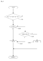
Fig. 3 ] A flow chart of transient retention judgment control. - [
Fig. 4 ] A flow chart of opening rate switching control. - [
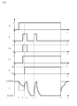
Fig. 5 ] A graph of time series variation of regeneration control. - [
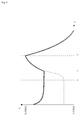
Fig. 6 ] A graph of time series variation enlargingFig. 5 partially. - An explanation will be given on an
engine 100 having an exhaustgas processing system 10 which is an embodiment of the present invention referring toFig. 1 .
Theengine 100 includes anengine body 11, anintake route 12, anexhaust route 13, an EGRroute 14 and an ECU (Engine Control Unit) 50. - The
intake route 12 is connected to an intake manifold of theengine body 11, and has anair cleaner 25 and anintake throttle valve 20. Theintake throttle valve 20 is arranged downstream theair cleaner 25 in theintake route 12.
Theexhaust route 13 is connected to an exhaust manifold of theengine body 11, and has anexhaust throttle valve 30 and a DPF (Diesel Particulate Filter) 35 as a particulate removing filter. Theexhaust throttle valve 30 is arranged upstream theDPF 35 in theexhaust route 13.
The EGRroute 14 is connected to the part of theintake route 12 downstream theintake throttle valve 20 and connected to the part of theexhaust route 13 upstream theexhaust throttle valve 30, and has anEGR valve 40 and anEGR cooler 45. - The ECU 50 is a control means of the
engine 100 and is connected to theintake throttle valve 20, theexhaust throttle valve 30, theEGR valve 40, anengine speed sensor 61 and afuel injection device 80. TheECU 50 controls the opening of theintake throttle valve 20, the opening of theexhaust throttle valve 30, and the opening of theEGR valve 40. - The exhaust
gas processing system 10 includes theECU 50, theintake throttle valve 20 and theDPF 35, and performs regeneration control which raises temperature of exhaust gas so as to make harmless PM (Particulate matters) collected in theDPF 35 and remove them.
The exhaustgas processing system 10 in this embodiment performs the regeneration control as discussed below. Namely, in the case of regenerating theDPF 35, when the temperature of the exhaust gas is lower than regeneration temperature of theDPF 35, a throttle opening S of theintake throttle valve 20 is closed from a normal opening Sn to a regeneration opening Sb so as to raise the temperature of the exhaust gas, whereby the PM collected in theDPF 35 are made harmless and removed. In this case, the regeneration opening Sb is smaller than the normal opening Sn.
The exhaustgas processing system 10 in this embodiment changes the throttle opening S of theintake throttle valve 20 so as to raise the temperature of the exhaust gas. However, instead of this construction, the throttle opening of theexhaust throttle valve 30 may alternatively be changed. - In the regeneration control in this embodiment, over the throttle process from the normal opening Sn to the regeneration opening Sb, the throttle opening S of the
intake throttle valve 20 is reduced gradually with an opening change rate R, and over the return process from the regeneration opening Sb to the normal opening Sn, the throttle opening S of theintake throttle valve 20 is increased gradually with the opening change rate R. - An explanation will be given on the construction of the
ECU 50 referring toFig. 2 .
The ECU 50 has a target throttleopening calculation part 51, a transientretention judgment part 52, an opening change rate switchingjudgment part 53 and a throttle opening calculation part 54.
The ECU 50 has an acceleration flag Fa as an acceleration request, a loading flag Fl as a loading request, a regeneration control flag Fd, and a transient retention flag Ft.
Furthermore, theECU 50 has a normal opening change rate Rn and a transient opening change rate Rt as the opening change rate R. - In the regeneration control, the
ECU 50 calculates the throttle opening S at each sampling period.
The ECU 50 detects an engine speed Ne with theengine speed sensor 61, and calculates a load factor La which is a ratio of an actual fuel injection amount to the maximum fuel injection amount determined for each target engine speed Nem. - The acceleration flag Fa is a flag judging whether the
engine 100 is accelerated or not. When the engine speed Ne is increased for not less than a predetermined value in a predetermined period, the ECU 50 judges that theengine 100 is accelerated, and the acceleration flag Fa turns into 1. - The loading flag Fl is a flag judging whether any load is applied on the
engine 100 or not. When the load factor La is increased for not less than a predetermined value in a predetermined period, theECU 50 judges that any load is applied on theengine 100, and the loading flag Fl turns into 1. - The regeneration control flag Fd is a flag judging whether the regeneration control is performed or not. The
ECU 50 judges whether the regeneration control is performed or not based on pressure difference between exhaust pressure sensors (not shown) provided before and behind theDPF 35 or assessed value of PM stacking amount. When the regeneration control is judged to be performed, the regeneration control flag Fd turns into 1. - The transient retention flag Ft is a flag indicating the state in which the
engine 100 is accelerated or the state in which any load is applied on theengine 100 in the regeneration control. The ECU 50 makes the transient retention flag Ft turn into 1 based on transient retention judgment control discussed later. - The normal opening change rate Rn is the opening change rate R reducing or increasing gradually the throttle opening S of the
intake throttle valve 20, and is the opening change rate R employed from the start of the regeneration control. On the other hand, the transient opening change rate Rt is the opening change rate R having larger opening change rate than the normal opening change rate Rn. - The target throttle
opening calculation part 51 calculates a target throttle opening Sm from the engine speed Ne, the load factor La and the regeneration control flag Fd. - The transient
retention judgment part 52 makes the transient retention flag Ft turn into 0 or 1 from the acceleration flag Fa, the loading flag Fl and the regeneration control flag Fd based on the transient retention judgment control discussed later. - The opening change rate
switching judgment part 53 switches the opening change rate R to the normal opening change rate Rn or the transient opening change rate Rt from the target throttle opening Sm, the acceleration flag Fa, the loading flag Fl, the regeneration control flag Fd and the transient retention flag Ft based on opening rate switching control discussed later. - The throttle opening calculation part 54 calculates the throttle opening S from the target throttle opening Sm calculated by the target throttle opening
calculation part 51 and the normal opening change rate Rn or the transient opening change rate Rt calculated by the opening change rateswitching judgment part 53. - An explanation will be given on the transient retention judgment control referring to
Fig. 3 .
The transientretention judgment part 52 of theECU 50 has a function making the transient retention flag Ft turn into 0 or 1 as the transient retention judgment control.
Firstly, the transientretention judgment part 52 confirms whether the regeneration control flag Fd is 0 or 1 at a step S110. When the regeneration control flag Fd is 1, the control shifts to a step S120. On the other hand, when the regeneration control flag Fd is 0, the transient retention flag Ft turns into 0 at a step S150. - Then, the transient
retention judgment part 52 confirms whether the transient retention flag Ft is 0 or 1 at the step S120. When the transient retention flag Ft is 0, the control shifts to a step S130. Next, the transientretention judgment part 52 confirms whether the acceleration flag Fa is 1 or not and whether the loading flag Fl is 1 or not at the step S130. When at least one of the acceleration flag Fa and the loading flag Fl is 1, the control shifts to a step S140. Then, the transientretention judgment part 52 makes the transient retention flag Ft turn into 1 at the step S 140. - An explanation will be given on the opening rate switching control referring to
Fig. 4 . The opening change rateswitching judgment part 53 of theECU 50 has a function switching the opening change rate R to the normal opening change rate Rn or the transient opening change rate Rt as the opening rate switching control.
Firstly, the opening change rateswitching judgment part 53 confirms whether the loading flag Fl, the acceleration flag Fa and the transient retention flag Ft are 1 or not at a step S210. When at least one of the loading flag Fl, the acceleration flag Fa and the transient retention flag Ft is 1, the control shifts to a step S220. On the other hand, when the loading flag Fl, the acceleration flag Fa and the transient retention flag Ft are not 1, the control shifts to a step S250 and the opening change rate R is switched to the normal opening change rate Rn.
At the step S220, the opening change rateswitching judgment part 53 confirms whether the opening change rate R is the transient opening change rate Rt or not. When the opening change rate R is not the transient opening change rate Rt (the opening change rate R is the normal opening change rate Rn), the control shifts to a step S230. - Then, the opening change rate
switching judgment part 53 calculates a throttle opening S(Rt) at the transient opening change rate Rt and a throttle opening S(Rn) at the normal opening change rate Rn on operation and confirms whether the throttle opening S(Rt) at the transient opening change rate Rt is larger than the throttle opening S(Rn) at the normal opening change rate Rn or not. When the throttle opening S(Rt) is larger than the throttle opening S(Rn), the control shifts to a step S240. On the other hand, when the throttle opening S(Rt) is not larger than the throttle opening S(Rn), the control shifts to the step S250.
Next, the opening change rateswitching judgment part 53 switches the opening change rate R to the transient opening change rate Rt at the step S240. - An explanation will be given on an embodiment of the regeneration control referring to
Figs. 5 and6 .
Figs. 5 and6 show time series variation of the regeneration control flag Fd, the loading flag Fl, the acceleration flag Fa, the transient retention flag Ft, the opening change rate R (the normal opening change rate Rn or the transient opening change rate Rt) and the throttle opening S. An explanation will be given on the throttle opening S following the time series (points A to G passing successively). Broken lines inFigs. 5 and6 show the throttle opening S(Rt) at the transient opening change rate Rt, and an alternate long and short dash line inFig. 6 shows the throttle opening S(Rn) at the normal opening change rate Rn. - At the point A, since the regeneration control flag Fd becomes 1, the regeneration control is started and the throttle opening S is reduced gradually from the normal opening Sn (100%) to the regeneration opening Sb (30%) with the normal opening change rate Rn. In this embodiment, the normal opening Sn is 100% of the opening of the
intake throttle valve 20, and the regeneration opening Sb is 30% of the opening of theintake throttle valve 20. - At the point B, since a loading request is inputted firstly in the regeneration control so that the acceleration flag Fa and the loading flag Fl become 1, the transient retention flag Ft becomes 1 by the transient retention judgment control.
In the regeneration control, when theengine 100 is accelerated or any load is applied on theengine 100, the temperature of the exhaust gas is raised so that the PM can be made harmless and removed. Accordingly, it is necessary to increase the throttle opening S gradually to the normal opening Sn.
However, in this embodiment, the throttle opening S is increased gradually to the normal opening Sn at the point C after passing a predetermined time from the point B, and only the transient retention flag Ft becomes 1 at the point B. The throttle opening S is reduced gradually toward the regeneration opening Sb from the point B to the point C. - At the point C, the throttle opening S(Rt) at the transient opening change rate Rt and the throttle opening S(Rn) at the normal opening change rate Rn are calculated on operation. Since the the throttle opening S(Rt) at the transient opening change rate Rt becomes larger than (exceeds) the throttle opening S(Rn) at the normal opening change rate Rn, the opening change rate R is switched from the normal opening change rate Rn to the transient opening change rate Rt by the opening change rate switching control.
In this case, the throttle opening S is increased gradually toward the normal opening Sn with the transient opening change rate Rt. - At the point D, since the acceleration request and the loading request are canceled and the loading flag Fl and the acceleration flag Fa become 0, the throttle opening S is reduced gradually from the normal opening Sn to the regeneration opening Sb with the transient opening change rate Rt.
At the point E, since the loading request is inputted and the loading flag Fl becomes 1, the throttle opening S is increased gradually from the regeneration opening Sb to the normal opening Sn with the transient opening change rate Rt.
At the point F, since the loading request is canceled and the loading flag Fl becomes 0, the throttle opening S is reduced gradually from the normal opening Sn to the regeneration opening Sb with the transient opening change rate Rt.
At the point G, since the regeneration control flag Fd becomes 0, the regeneration control is finished. Simultaneously, by the opening change rate switching control, the opening change rate R is switched from the transient opening change rate Rt to the normal opening change rate Rn. Then, throttle opening S is increased gradually from the regeneration opening Sb to the normal opening Sn with the normal opening change rate Rn. - The construction brings following effects.
In the case of the regeneration control of theDPF 35, the throttle opening S of theintake throttle valve 20 is reduced or increased gradually with the predetermined opening change rate R, whereby sudden change of engine noise in the case of the shift to the regeneration state with the regeneration opening Sb and the case of the return from the regeneration state with the regeneration opening Sb to that with the normal opening Sn. - At the period after starting the regeneration control of the
DPF 35 from the initial input of the acceleration flag Fa or the loading flag Fl to the finish of the regeneration, the throttle opening S is reduced or increased gradually with the transient opening change rate Rt larger than the normal opening change rate Rn, whereby the responsibility of theintake throttle valve 20 is improved and the time until the next regeneration control with the regeneration opening Sb is shortened. Accordingly, the temperature of the exhaust gas can be raised quickly to the regeneration temperature after finishing the acceleration or after releasing the load. - Furthermore, when the throttle opening S(Rt) at the transient opening change rate Rt exceeds the throttle opening S(Rn) at the normal opening change rate Rn, the opening change rate R is switched to the transient opening change rate Rt, whereby the momentary reduction of the throttle opening S of the
intake throttle valve 20 following the switch of the opening change rate R can be prevented. - The present invention can be employed in an exhaust gas processing system performing regeneration control of a DPF by raising temperature of exhaust gas by throttling an intake throttle valve or an exhaust throttle valve.
Claims (3)
- An exhaust gas processing system for an engine in which a particulate removing filter for exhaust gas is provided in an exhaust passage, and in a case of regeneration of the particulate removing filter, an intake throttle valve or an exhaust throttle valve is throttled to a regeneration opening smaller than a normal opening and the valve is returned from the regeneration opening to the normal opening after regenerating the particulate removing filter, characterized in that
the opening of the intake throttle valve or the exhaust throttle valve in a throttle process from the normal opening to the regeneration opening and a return process from the regeneration opening to the normal opening is changed with an opening change rate which decreases or increases gradually. - The exhaust gas processing system for the engine according to claim 1,
wherein the intake throttle valve or the exhaust throttle valve set at the regeneration opening is returned to the normal opening when acceleration request or loading request is inputted while the regeneration control of the particulate removing filter is performed,
wherein the intake throttle valve or the exhaust throttle valve is throttled to the regeneration opening again when the acceleration request or the loading request is canceled,
wherein the opening change rate is set to a normal opening change rate or a transient opening change rate larger than the normal opening change rate, and
wherein the opening change rate at the throttle process and the return process of the intake throttle valve or the exhaust throttle valve is switched from the normal opening change rate to the transient opening change rate in a period after starting the regeneration control of the particulate removing filter from initial input of the acceleration request or the loading request to end of the regeneration control. - The exhaust gas processing system for the engine according to claim 2, wherein the opening change rate is switched from the normal opening change rate to the transient opening change rate when the opening of the intake throttle valve or the exhaust throttle valve with the transient opening change rate exceeds that with the normal opening change rate.
Applications Claiming Priority (2)
| Application Number | Priority Date | Filing Date | Title |
|---|---|---|---|
| JP2010052003A JP5530226B2 (en) | 2010-03-09 | 2010-03-09 | Engine exhaust gas treatment system |
| PCT/JP2011/054853 WO2011111591A1 (en) | 2010-03-09 | 2011-03-03 | System of treating exhaust gas of engine |
Publications (2)
| Publication Number | Publication Date |
|---|---|
| EP2546495A1 true EP2546495A1 (en) | 2013-01-16 |
| EP2546495A4 EP2546495A4 (en) | 2017-07-19 |
Family
ID=44563395
Family Applications (1)
| Application Number | Title | Priority Date | Filing Date |
|---|---|---|---|
| EP11753250.7A Ceased EP2546495A4 (en) | 2010-03-09 | 2011-03-03 | System of treating exhaust gas of engine |
Country Status (4)
| Country | Link |
|---|---|
| US (1) | US8893479B2 (en) |
| EP (1) | EP2546495A4 (en) |
| JP (1) | JP5530226B2 (en) |
| WO (1) | WO2011111591A1 (en) |
Families Citing this family (7)
| Publication number | Priority date | Publication date | Assignee | Title |
|---|---|---|---|---|
| US20110146246A1 (en) * | 2009-12-22 | 2011-06-23 | Caterpillar Inc. | Regeneration assist transition period |
| WO2013099980A1 (en) * | 2011-12-27 | 2013-07-04 | ヤンマー株式会社 | Engine device |
| FR2993931B1 (en) * | 2012-07-24 | 2014-08-08 | Peugeot Citroen Automobiles Sa | METHOD FOR REGENERATING A PARTICULATE FILTER EQUIPPED WITH AN EXHAUST LINE OF A MOTOR VEHICLE |
| JP6203545B2 (en) * | 2013-06-07 | 2017-09-27 | ヤンマー株式会社 | Exhaust gas purification device |
| JP6156284B2 (en) * | 2014-08-07 | 2017-07-05 | トヨタ自動車株式会社 | Combustion control device for internal combustion engine |
| KR20160066243A (en) * | 2014-12-02 | 2016-06-10 | 현대자동차주식회사 | Particulate filter regeneration method of diesel hybrid vehicle |
| KR101762281B1 (en) * | 2016-06-20 | 2017-07-31 | 현대자동차주식회사 | Variable Confluence portion Structure of Exhaust Pipe |
Family Cites Families (16)
| Publication number | Priority date | Publication date | Assignee | Title |
|---|---|---|---|---|
| DE3912301A1 (en) * | 1989-04-14 | 1990-10-25 | Daimler Benz Ag | METHOD FOR REGENERATING A CARBON PARTICLE FILTER ARRANGED IN THE EXHAUST PIPE OF AN AIR COMPRESSING INTERNAL COMBUSTION ENGINE |
| ES2227306T3 (en) * | 2000-07-24 | 2005-04-01 | Toyota Jidosha Kabushiki Kaisha | EXHAUST GAS PURIFIER DEVICE. |
| JP2002276405A (en) * | 2001-03-19 | 2002-09-25 | Isuzu Motors Ltd | Diesel engine exhaust purification system |
| JP3835241B2 (en) * | 2001-10-15 | 2006-10-18 | トヨタ自動車株式会社 | Exhaust gas purification device for internal combustion engine |
| US6931842B2 (en) * | 2002-11-29 | 2005-08-23 | Nissan Motor Co., Ltd. | Regeneration of diesel particulate filter |
| JP3915728B2 (en) * | 2003-03-31 | 2007-05-16 | マツダ株式会社 | Engine control device |
| JP4446676B2 (en) * | 2003-04-09 | 2010-04-07 | トヨタ自動車株式会社 | Throttle control device for internal combustion engine |
| JP2005264785A (en) * | 2004-03-17 | 2005-09-29 | Nissan Motor Co Ltd | Diesel engine exhaust aftertreatment system |
| JP4375086B2 (en) * | 2004-03-30 | 2009-12-02 | いすゞ自動車株式会社 | Engine exhaust throttle valve operating device |
| JP4193801B2 (en) * | 2005-01-13 | 2008-12-10 | トヨタ自動車株式会社 | Exhaust gas purification system for internal combustion engine |
| JP4453602B2 (en) * | 2005-05-18 | 2010-04-21 | トヨタ自動車株式会社 | Exhaust gas purification system for internal combustion engine |
| JP4017010B2 (en) * | 2006-02-01 | 2007-12-05 | いすゞ自動車株式会社 | Exhaust gas purification system control method and exhaust gas purification system |
| JP4857957B2 (en) * | 2006-06-30 | 2012-01-18 | 日産自動車株式会社 | Engine control device |
| FR2910058B1 (en) * | 2006-12-14 | 2011-03-04 | Renault Sas | METHOD FOR LIMITING AIR INTAKE NOISE PRODUCED AT THE END OF REGENERATION OF THE EXHAUST GAS POST-TREATMENT SYSTEM |
| JP2008180095A (en) * | 2007-01-23 | 2008-08-07 | Nissan Motor Co Ltd | Engine starter |
| JP2009150278A (en) * | 2007-12-19 | 2009-07-09 | Mitsubishi Fuso Truck & Bus Corp | Method and device for controlling intake during automatic regeneration of particulate filter |
-
2010
- 2010-03-09 JP JP2010052003A patent/JP5530226B2/en not_active Expired - Fee Related
-
2011
- 2011-03-03 US US13/583,374 patent/US8893479B2/en not_active Expired - Fee Related
- 2011-03-03 EP EP11753250.7A patent/EP2546495A4/en not_active Ceased
- 2011-03-03 WO PCT/JP2011/054853 patent/WO2011111591A1/en not_active Ceased
Non-Patent Citations (1)
| Title |
|---|
| See references of WO2011111591A1 * |
Also Published As
| Publication number | Publication date |
|---|---|
| JP2011185177A (en) | 2011-09-22 |
| US20120324871A1 (en) | 2012-12-27 |
| JP5530226B2 (en) | 2014-06-25 |
| EP2546495A4 (en) | 2017-07-19 |
| WO2011111591A1 (en) | 2011-09-15 |
| US8893479B2 (en) | 2014-11-25 |
Similar Documents
| Publication | Publication Date | Title |
|---|---|---|
| US8893479B2 (en) | System of treating exhaust gas of engine | |
| EP1882088B1 (en) | Exhaust gas purification system for internal combustion engine | |
| EP1759099B1 (en) | Exhaust gas control apparatus for internal combustion engine | |
| EP1679430A1 (en) | Engine control apparatus and method | |
| EP1577524A2 (en) | Regeneration of diesel particulate filter | |
| JP2005240756A (en) | Engine control device | |
| EP2546483B1 (en) | Exhaust gas treatment system for engine | |
| EP2578858B1 (en) | Exhaust gas purification system | |
| CN103237968A (en) | Control device for internal combustion engine with supercharger | |
| JP2011247143A (en) | Exhaust emission control system | |
| CN102939441B (en) | Exhaust-gas purification system | |
| EP1900928A1 (en) | Exhaust gas purification system in internal combustion engine | |
| JP4687793B2 (en) | Exhaust gas recirculation device | |
| US7543446B2 (en) | System for controlling regeneration of exhaust gas aftertreatment components | |
| EP2163742B1 (en) | Exhaust gas purification system for internal combustion engine | |
| JP4670592B2 (en) | Exhaust gas recirculation system for internal combustion engines | |
| EP1790837A1 (en) | Exhaust emission control system of internal combustion engine | |
| JP2012002213A (en) | Fault detection device for differential pressure sensor | |
| JP4978187B2 (en) | Control system and control method for internal combustion engine | |
| EP2578824A1 (en) | System for purifying exhaust gas in upland area | |
| JP7059912B2 (en) | Exhaust purification device for internal combustion engine | |
| JP4044836B2 (en) | Exhaust gas purification device for internal combustion engine | |
| JP5182988B2 (en) | Exhaust gas purification device for internal combustion engine | |
| JP2010159687A (en) | Exhaust emission control device of engine | |
| JP2008133740A (en) | Fuel injection control device for internal combustion engine |
Legal Events
| Date | Code | Title | Description |
|---|---|---|---|
| PUAI | Public reference made under article 153(3) epc to a published international application that has entered the european phase |
Free format text: ORIGINAL CODE: 0009012 |
|
| 17P | Request for examination filed |
Effective date: 20121009 |
|
| AK | Designated contracting states |
Kind code of ref document: A1 Designated state(s): AL AT BE BG CH CY CZ DE DK EE ES FI FR GB GR HR HU IE IS IT LI LT LU LV MC MK MT NL NO PL PT RO RS SE SI SK SM TR |
|
| DAX | Request for extension of the european patent (deleted) | ||
| RA4 | Supplementary search report drawn up and despatched (corrected) |
Effective date: 20170621 |
|
| RIC1 | Information provided on ipc code assigned before grant |
Ipc: F01N 3/02 20060101ALI20170614BHEP Ipc: F02D 41/02 20060101ALI20170614BHEP Ipc: F02D 9/02 20060101AFI20170614BHEP Ipc: F02M 26/00 20160101ALN20170614BHEP Ipc: F01N 3/023 20060101ALI20170614BHEP Ipc: F02D 41/10 20060101ALI20170614BHEP Ipc: F01N 9/00 20060101ALI20170614BHEP Ipc: F02D 41/14 20060101ALN20170614BHEP Ipc: F02D 33/02 20060101ALI20170614BHEP Ipc: F01N 1/16 20060101ALI20170614BHEP |
|
| STAA | Information on the status of an ep patent application or granted ep patent |
Free format text: STATUS: EXAMINATION IS IN PROGRESS |
|
| 17Q | First examination report despatched |
Effective date: 20200323 |
|
| RAP1 | Party data changed (applicant data changed or rights of an application transferred) |
Owner name: YANMAR POWER TECHNOLOGY CO., LTD. |
|
| REG | Reference to a national code |
Ref country code: DE Ref legal event code: R003 |
|
| STAA | Information on the status of an ep patent application or granted ep patent |
Free format text: STATUS: THE APPLICATION HAS BEEN REFUSED |
|
| 18R | Application refused |
Effective date: 20220103 |