EP2546437A2 - Container security apparatus - Google Patents
Container security apparatus Download PDFInfo
- Publication number
- EP2546437A2 EP2546437A2 EP11753564A EP11753564A EP2546437A2 EP 2546437 A2 EP2546437 A2 EP 2546437A2 EP 11753564 A EP11753564 A EP 11753564A EP 11753564 A EP11753564 A EP 11753564A EP 2546437 A2 EP2546437 A2 EP 2546437A2
- Authority
- EP
- European Patent Office
- Prior art keywords
- container
- opening
- module
- power
- closing
- Prior art date
- Legal status (The legal status is an assumption and is not a legal conclusion. Google has not performed a legal analysis and makes no representation as to the accuracy of the status listed.)
- Withdrawn
Links
- 238000007789 sealing Methods 0.000 claims description 49
- 238000003780 insertion Methods 0.000 claims description 47
- 230000037431 insertion Effects 0.000 claims description 47
- 230000008878 coupling Effects 0.000 claims description 45
- 238000010168 coupling process Methods 0.000 claims description 45
- 238000005859 coupling reaction Methods 0.000 claims description 45
- 230000006835 compression Effects 0.000 claims description 29
- 238000007906 compression Methods 0.000 claims description 29
- 238000004891 communication Methods 0.000 claims description 22
- 230000003139 buffering effect Effects 0.000 claims description 16
- 238000012546 transfer Methods 0.000 claims description 10
- 238000012423 maintenance Methods 0.000 claims description 4
- 230000007257 malfunction Effects 0.000 claims description 4
- 239000000463 material Substances 0.000 claims description 4
- 229910001220 stainless steel Inorganic materials 0.000 claims description 4
- 239000010935 stainless steel Substances 0.000 claims description 4
- 238000005728 strengthening Methods 0.000 claims description 4
- 238000010295 mobile communication Methods 0.000 claims description 3
- 238000009751 slip forming Methods 0.000 claims description 3
- 230000000149 penetrating effect Effects 0.000 claims description 2
- 238000010586 diagram Methods 0.000 description 4
- 230000000694 effects Effects 0.000 description 4
- 230000007246 mechanism Effects 0.000 description 4
- 230000006870 function Effects 0.000 description 3
- 239000000126 substance Substances 0.000 description 2
- 230000005540 biological transmission Effects 0.000 description 1
- 230000008602 contraction Effects 0.000 description 1
- 238000005553 drilling Methods 0.000 description 1
- 239000004973 liquid crystal related substance Substances 0.000 description 1
- 238000000034 method Methods 0.000 description 1
- 238000012545 processing Methods 0.000 description 1
- 230000007847 structural defect Effects 0.000 description 1
Images


Classifications
-
- E—FIXED CONSTRUCTIONS
- E05—LOCKS; KEYS; WINDOW OR DOOR FITTINGS; SAFES
- E05B—LOCKS; ACCESSORIES THEREFOR; HANDCUFFS
- E05B73/00—Devices for locking portable objects against unauthorised removal; Miscellaneous locking devices
- E05B73/0017—Anti-theft devices, e.g. tags or monitors, fixed to articles, e.g. clothes, and to be removed at the check-out of shops
- E05B73/0023—Containers, boxes, cases or the like, e.g. for compact discs or video-cassettes, specially adapted therefor
-
- E—FIXED CONSTRUCTIONS
- E05—LOCKS; KEYS; WINDOW OR DOOR FITTINGS; SAFES
- E05C—BOLTS OR FASTENING DEVICES FOR WINGS, SPECIALLY FOR DOORS OR WINDOWS
- E05C19/00—Other devices specially designed for securing wings, e.g. with suction cups
- E05C19/18—Portable devices specially adapted for securing wings
- E05C19/186—Portable devices specially adapted for securing wings with a pair of hooks, which are movable towards each other for grasping of an element on the wing, respectively on the frame, or for grasping of an element on each of the wings forming a double door
-
- B—PERFORMING OPERATIONS; TRANSPORTING
- B65—CONVEYING; PACKING; STORING; HANDLING THIN OR FILAMENTARY MATERIAL
- B65D—CONTAINERS FOR STORAGE OR TRANSPORT OF ARTICLES OR MATERIALS, e.g. BAGS, BARRELS, BOTTLES, BOXES, CANS, CARTONS, CRATES, DRUMS, JARS, TANKS, HOPPERS, FORWARDING CONTAINERS; ACCESSORIES, CLOSURES, OR FITTINGS THEREFOR; PACKAGING ELEMENTS; PACKAGES
- B65D90/00—Component parts, details or accessories for large containers
-
- E—FIXED CONSTRUCTIONS
- E05—LOCKS; KEYS; WINDOW OR DOOR FITTINGS; SAFES
- E05B—LOCKS; ACCESSORIES THEREFOR; HANDCUFFS
- E05B39/00—Locks giving indication of authorised or unauthorised unlocking
-
- E—FIXED CONSTRUCTIONS
- E05—LOCKS; KEYS; WINDOW OR DOOR FITTINGS; SAFES
- E05B—LOCKS; ACCESSORIES THEREFOR; HANDCUFFS
- E05B39/00—Locks giving indication of authorised or unauthorised unlocking
- E05B39/005—Locks with means for tracking the location of locked items, e.g. freight containers
-
- E—FIXED CONSTRUCTIONS
- E05—LOCKS; KEYS; WINDOW OR DOOR FITTINGS; SAFES
- E05B—LOCKS; ACCESSORIES THEREFOR; HANDCUFFS
- E05B47/00—Operating or controlling locks or other fastening devices by electric or magnetic means
- E05B47/0001—Operating or controlling locks or other fastening devices by electric or magnetic means with electric actuators; Constructional features thereof
-
- E—FIXED CONSTRUCTIONS
- E05—LOCKS; KEYS; WINDOW OR DOOR FITTINGS; SAFES
- E05B—LOCKS; ACCESSORIES THEREFOR; HANDCUFFS
- E05B17/00—Accessories in connection with locks
- E05B17/22—Means for operating or controlling lock or fastening device accessories, i.e. other than the fastening members, e.g. switches, indicators
- E05B17/226—Displays on locks, e.g. LED or LCD screens
-
- E—FIXED CONSTRUCTIONS
- E05—LOCKS; KEYS; WINDOW OR DOOR FITTINGS; SAFES
- E05B—LOCKS; ACCESSORIES THEREFOR; HANDCUFFS
- E05B47/00—Operating or controlling locks or other fastening devices by electric or magnetic means
- E05B2047/0097—Operating or controlling locks or other fastening devices by electric or magnetic means including means for monitoring voltage, e.g. for indicating low battery state
-
- E—FIXED CONSTRUCTIONS
- E05—LOCKS; KEYS; WINDOW OR DOOR FITTINGS; SAFES
- E05B—LOCKS; ACCESSORIES THEREFOR; HANDCUFFS
- E05B45/00—Alarm locks
- E05B45/005—Chain-locks, cable-locks or padlocks with alarms
-
- E—FIXED CONSTRUCTIONS
- E05—LOCKS; KEYS; WINDOW OR DOOR FITTINGS; SAFES
- E05B—LOCKS; ACCESSORIES THEREFOR; HANDCUFFS
- E05B83/00—Vehicle locks specially adapted for particular types of wing or vehicle
- E05B83/02—Locks for railway freight-cars, freight containers or the like; Locks for the cargo compartments of commercial lorries, trucks or vans
- E05B83/08—Locks for railway freight-cars, freight containers or the like; Locks for the cargo compartments of commercial lorries, trucks or vans with elongated bars for actuating the fastening means
- E05B83/10—Rotary bars
-
- Y—GENERAL TAGGING OF NEW TECHNOLOGICAL DEVELOPMENTS; GENERAL TAGGING OF CROSS-SECTIONAL TECHNOLOGIES SPANNING OVER SEVERAL SECTIONS OF THE IPC; TECHNICAL SUBJECTS COVERED BY FORMER USPC CROSS-REFERENCE ART COLLECTIONS [XRACs] AND DIGESTS
- Y10—TECHNICAL SUBJECTS COVERED BY FORMER USPC
- Y10T—TECHNICAL SUBJECTS COVERED BY FORMER US CLASSIFICATION
- Y10T70/00—Locks
- Y10T70/50—Special application
- Y10T70/5004—For antitheft signaling device on protected article
Definitions
- the present invention relates to a container security apparatus, and more particularly, to a container security apparatus for safely transporting a container.
- containers are widely used as means for shipping goods. Particularly, when transporting goods by land from a harbor to an airport, goods are loaded in containers and transported using vehicles.
- Such containers are left as they are in a harbor that is a starting point for a long period or are transported for a long time to a destination in a state of transporting via vehicles. In this case, there occur many robbery cases of goods loaded in containers.
- General containers include door latch mechanism to lock a door thereof.
- a seal itself may be unsealed using a general cutting device or it is easy to take the seal to pieces by using a duplication thereof.
- An aspect of the present invention provides a container security apparatus attached to both opening/closing bars of a container to be detachable to sense whether the container is opened or not and transmitting the sensed opening/closing information to a remote location to check in real time whether the container is sealed or not, thereby safely transporting the container.
- An aspect of the present invention also provides a container security apparatus capable of checking a present location of a container and checking a case when a container deviates from the designated path in real time.
- a container security apparatus including: a main cover unit with a display part displaying a present state; a main frame coupled with the main cover unit internally, including a first insertion part surrounding one of both opening/closing bars of a container, formed on one side thereof; a first body unit coupled with the main frame internally, including a power-supply part with a built-in battery for supplying power stably mounted thereon; and a sensing part including a guide groove formed penetrating thereinside, a plurality of coupling holes connected to the guide groove, into which a coupling element is inserted, and a sealing sensor whose one end is connected to the coupling element, sensing whether the container is opened or not; a second body unit coupled with the first body unit internally, including an antenna part with a built-in antenna stably mounted thereon; and a board part with a board stably mounted thereon, the board including a sealing module electrically connected to another end of the sealing sensor and transmitting the opening
- the lock frame may include a wire line formed thereinside, where the wire is inserted in and fastened thereto.
- the lock frame may include a wire groove formed thereinside, where the wire passes through and is fastened thereto.
- the lock frame may be formed of stainless steel.
- the flat plates may include: a first flat plate connected between one end of the second insertion part and the detachable plate in a single body; and a second flat plate connected to another end of the second insertion part in a single body, wherein the wire is continuously formed from the detachable plate to the second flat plate.
- conductive elements respectively, electrically connected to the coupling element.
- the communication module may be formed of one of code division multiple access (CDMA), wideband code division multiple access (WCDMA), wireless broadband Internet (WiBro), wireless fidelity (WiFi), and global system/standard for mobile communication (GSM) module.
- CDMA code division multiple access
- WCDMA wideband code division multiple access
- WiBro wireless broadband Internet
- WiFi wireless fidelity
- GSM global system/standard for mobile communication
- the board may further include a database (DB) module for storing container information such as a transfer path, a number, and a license plate number of the container.
- DB database
- the board may further include a warning module generating and transmitting an alarm signal when the container is deviated from a transfer path thereof or sealing of the container is illegally released.
- the apparatus may further include, when the alarm signal is generated, function of resetting data stored when illegally opening the container, arbitrarily operating the container, or turning off the power of the container.
- the warning module may generate and transmit the alarm signal when a present charge capacity of the built-in battery is 25% or less of a maximum charge capacity thereof.
- the insertion part may include: a sub frame connected to one end of the main frame in a single body and surrounding the opening/closing bar; a compression controller including a shaft whose both ends are fastened to the sub frame externally, a compression cam rotation on an axis of the shaft, and an opening/closing handle connected to the compression cam in a single body; a tightening element installed inside the sub frame and transferred toward the opening/closing bar by a pressure applied by the compression cam; a spring section installed on both sides of the shaft and connected from the outside of the sub frame to a top of the tightening element; and a buffering element installed inside between the tightening element and the sub frame and relieving an impact with the opening/closing bar and improving a grip force.
- the spring section may include: a plurality of vertical supporters whose one end is vertically connected to the tightening element; a plurality of springs provided surrounding the outside of the vertical supporters; and a spring stopper provided on other ends of the vertical supporters and connecting the plurality of vertical supporters.
- a buffering element relieving an impact with the opening/closing bar and improving a grip force.
- the buffering element may be formed of a material capable of improving the grip force by strengthening a frictional force such as rubber.
- the power-supply part may include a power-supply switch formed on one side thereof, the power-supply switch turned on when the lock frame is coupled with the sensing part and turned off when the lock frame is detached from the sensing part.
- the power-supply part may turn on the power when the lock frame is coupled with the sensing part and the opening/closing handle is pressurized and may turn off the power when the lock frame is detached from the sensing part and the opening/closing handle is relieved.
- the power-supply part may include a battery port for electrically charging the built-in battery.
- the coupling element may be formed of one of a pin, a bolt, and a switch.
- the display part may display a state whether the power is turned on or off, a state of a residual amount of the battery, a communication state, and a sealed state.
- the main cover unit may include a sub cover part covering the coupling element and preventing malfunction of the coupling element.
- the container security apparatus provides an effect of safely transporting the container by easily attaching/detaching the apparatus to/from both opening/closing bars of a container, sensing whether the container is opened or not, transmitting opening/closing information to a remote location, and checking whether the container is sealed or not in real-time.
- the apparatus provides an effect of checking in real-time a location of the container and whether the container is deviated from a transfer path thereof.
- the apparatus provides an effect of being applied to not only container vehicles but also various vehicles transferred maintaining security thereof such as refrigerator vehicles.
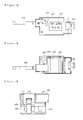
- FIG. 1 is a front view illustrating a container security apparatus according to an embodiment of the present invention
- FIG. 2 is a rear view illustrating the container security apparatus of FIG. 1
- FIG. 3 is a left-side view illustrating the container security apparatus of FIG. 1
- FIG. 4 is a right-side view illustrating the container security apparatus of FIG. 1
- FIG. 5 is a top view illustrating the container security apparatus of FIG. 1
- FIG. 6 is a bottom view illustrating the container security apparatus of FIG. 1
- FIG. 7 is a schematic perspective view illustrating the container security apparatus of FIG. 1 ;
- the container security apparatus includes, as shown in FIGs. 1 to 7 , a main cover unit 100, a main frame 200, a first body unit 300, a second body unit 400, and a lock frame 600.
- FIG. 8 is a configuration view illustrating the main cover unit 100 of the container security apparatus according to an embodiment of the present invention.
- the main cover unit 100 is coupled with the main frame 200 externally, covers the main frame 200 and a first insertion part 500 that will be described later, and includes a display part 110 and a sub cover part 120.
- the display part 110 displays a present state of the container security apparatus.
- the sub cover part 120 covers a coupling element 323 passing through and coupled with the main cover unit 100, which will be described later, and prevents the malfunction of the coupling element 323.
- FIG. 9 is a configuration view illustrating the main frame 200 of the container security apparatus according to an embodiment of the present invention.
- the main frame 200 is coupled with the main cover unit 100 internally and equipped with the first insertion part 500 covering and fastened to one of both opening/closing bars of a container on one side thereof.
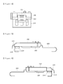
- FIG. 18 is a view illustrating the opening/closing bar 700 fastened to the first insertion part 500 according to an embodiment of the present invention
- FIG. 19 is a view illustrating an operation of fastening the opening/closing bar 700 to the first insertion part 500 according to the present invention.
- the first insertion part 500 includes a sub frame 510, a compression controller 520, a tightening element 530, a spring section 540, and a buffering element 550.
- the sub frame 510 is connected to one side of the main frame 200 in a single body and may surround and support the opening/closing bar 700 externally.
- the compression controller 520 may perform one of fastening the opening/closing bar 700 to the first insertion part 500 and separating the opening/closing bar 700 from the first insertion part 500, as shown in FIGs. 4 and 18 , may include a shaft 521, a compression cam 522, and an opening/closing handle 523.
- the tightening element 530 is installed inside the sub frame 510 and transfers toward the opening/closing bar 700 due to a pressure of the compression cam 520, and may be closely attached to the opening/closing bar 700.
- the spring section 540 is installed on both sides of the shaft 521, may be connected from the outside of the sub frame 510 to a top of the tightening element 530, and may restore the tightening element 530 to an original location thereof when the opening/closing handle 523 is rotationally transferred from a bottom to a top to release the pressure of the compression cam 522 toward the tightening element 530.
- the buffering element 550 is provided inside between the tightening element 530 and the sub frame 510 to buffer an impact between the tightening element 530 and the opening/closing bar 700 and may improve grip thereof.
- FIG. 10 is a configuration view illustrating the first body unit 300 of the container security apparatus according to an embodiment of the present invention
- FIG. 21 is a view illustrating an operation of turning on or off a power-supply switch 312 according to an embodiment of the present invention.
- the first body unit 300 is coupled with the main frame 200 internally and includes, as shown in FIG. 10 , a power-supply part 310 and a sensing part 320.
- the power-supply part 310 includes a built-in battery 311 stably mounted thereon to apply power and the power-supply switch 312 turned on when the lock frame 600 is coupled with the sensing part 320 and turned off when the lock frame 600 is detached from the sensing part 320 and simultaneously, the compression of the opening/closing handle 523 is released to separate the opening/closing bar 700 from the first insertion part 500.
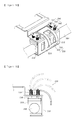
- FIG. 14 is a cross-sectional view illustrating the lock frame 600 coupled with the sensing part 320 according to an embodiment of the present invention.
- the sensing part 320 includes, as shown in FIG. 14 , a guide groove 321, a plurality of coupling holes 322, and a sealing sensor 324.
- FIG. 11 is a configuration view illustrating the second body unit 400 of the container security apparatus according to an embodiment of the present invention.
- the second body unit 400 is coupled with the first body unit 300 internally and includes, as shown in FIG. 11 , an antenna part 410 and a board part 420.
- the antenna part 410 includes a built-in antenna stably mounted thereon.
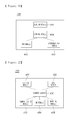
- FIGS. 16 and 17 are block views illustrating a board 430 according to an embodiment of the present invention.
- the board part 420 includes the board 430 stably mounted thereon, and the board 430 includes, as shown in FIG. 16 , a sealing module 431, a global positioning system (GPS) module 432, a communication module 433, and a control module 436.
- a sealing module 431 includes, as shown in FIG. 16 , a sealing module 431, a global positioning system (GPS) module 432, a communication module 433, and a control module 436.
- GPS global positioning system
- FIGs. 12 and 13 are configuration views illustrating the lock frame 600 of the container security apparatus according to an embodiment of the present invention.
- the lock frame 600 may be formed of stainless steel and includes, as shown in FIGS. 12 and 13 , a second insertion part 610, flat plates 620, a detachable plate 630, and a wire 640.
- FIG. 20 is a view illustrating the opening/closing bar 700 fastened to the second insertion part 610 according to an embodiment of the present invention.
- the second insertion part 610 surrounds another opening/closing bar 700 of the container and is fastened thereto as shown in FIG. 20 .
- the flat plate is, as shown in FIGs. 12 and 13 , connected to both ends of the second insertion part 610 in a single body.
- FIG. 15 is a partial top view illustrating the detachable plate 630 according to an embodiment of the present invention.
- the detachable plate 630 is, as shown in FIG. 15 , connected to one of two flat plates 620, for example, a first flat plate 621 and includes a plurality of detachable holes 631 corresponding to coupling holes 322.
- the detachable plate 630 is slidably inserted into the guide groove 321 in such a way that the detachable hole 631 corresponds to a location of the coupling hole 322 and is coupled with the sensing part 320 by the coupling element 323.
- the wire 640 includes, as shown in FIGs. 12 and 13 , one end connected an input detachable hole 631a and another end connected to an output detachable hole 631b and is provided from the detachable plate 630 to the second flat plate 622.
- FIG. 1 is a front view illustrating a container security apparatus according to an embodiment of the present invention
- FIG. 2 is a rear view illustrating the container security apparatus of FIG. 1
- FIG. 3 is a left-side view illustrating the container security apparatus of FIG. 1
- FIG. 4 is a right-side view illustrating the container security apparatus of FIG. 1
- FIG. 5 is a top view illustrating the container security apparatus of FIG. 1
- FIG. 6 is a bottom view illustrating the container security apparatus of FIG. 1
- FIG. 7 is a schematic perspective view illustrating the container security apparatus of FIG. 1 ;
- the container security apparatus includes, as shown in FIGs. 1 to 7 , a main cover unit 100, a main frame 200, a first body unit 300, a second body unit 400, and a lock frame 600.
- FIG. 8 is a configuration view illustrating the main cover unit 100 of the container security apparatus according to an embodiment of the present invention.
- the main cover unit 100 is coupled with the main frame 200 externally, covers the main frame 200 and a first insertion part 500 that will be described later, and includes a display part 110 and a sub cover part 120.
- the display part 110 displays a present state of the container security apparatus.
- the display part 110 may be formed of one of a liquid crystal display (LCD) and a light-emitting diode (LED) and may display the present status of the container security apparatus such as the status of turning the container security apparatus on/off, the status of a residual quantity of a battery, a status of communication, and a status of sealing.
- LCD liquid crystal display
- LED light-emitting diode
- the sub cover part 120 covers a coupling element 323 passing through and coupled with the main cover unit 100, which will be described later, and prevents the malfunction of the coupling element 323.
- the sub cover part 120 may open or shut the coupling element 323 by slidably transferring on the main cover unit 100 or by using a hinge.
- FIG. 9 is a configuration view illustrating the main frame 200 of the container security apparatus according to an embodiment of the present invention.
- the main frame 200 is coupled with the main cover unit 100 internally and equipped with the first insertion part 500 covering and fastened to one of both opening/closing bars of a container on one side thereof.
- FIG. 18 is a view illustrating the opening/closing bar 700 fastened to the first insertion part 500 according to an embodiment of the present invention
- FIG. 19 is a view illustrating an operation of fastening the opening/closing bar 700 to the first insertion part 500 according to the present invention.
- the first insertion part 500 includes a sub frame 510, a compression controller 520, a tightening element 530, a spring section 540, and a buffering element 550.
- the sub frame 510 is connected to one side of the main frame 200 in a single body and may surround and support the opening/closing bar 700 externally.
- the sub frame 510 may be formed in various shapes, and more particularly, a shape of " ⁇ " in the present embodiment.
- the compression controller 520 may perform one of fastening the opening/closing bar 700 to the first insertion part 500 and separating the opening/closing bar 700 from the first insertion part 500, as shown in FIGs. 4 and 18 , may include a shaft 521, a compression cam 522, and an opening/closing handle 523.
- the shaft 521 passes through a hollow portion of the compression cam 522 and both ends thereof are fastened to the outside of the sub frame 510.
- the compression cam 522 is formed in a rectangular shape whose one set of sides are longer than another set of sides and is rotationally transferred on an axis of the shaft 521.
- the opening/closing handle 523 is formed in a parabolic shape with a fluent curve portion formed thereon and is connected to the compression cam 522 in a single body, thereby transferring a rotational force to the compression cam 522.
- the opening/closing handle 523 is rotationally transferred from a top to a bottom in such a way that the compression cam 522 simultaneously rotates on an axis of the shaft 521 and the tightening element 530 is compressed.
- the tightening element 530 is installed inside the sub frame 510 and transfers toward the opening/closing bar 700 due to a pressure of the compression cam 520, and may be closely attached to the opening/closing bar 700.
- the spring section 540 is installed on both sides of the shaft 521, may be connected from the outside of the sub frame 510 to a top of the tightening element 530, and may restore the tightening element 530 to an original location thereof when the opening/closing handle 523 is rotationally transferred from a bottom to a top to release the pressure of the compression cam 522 toward the tightening element 530.
- the spring section 540 includes, as shown in FIG. 18 , a plurality of vertical supporters 541, a plurality of springs 543, and a spring stopper 542.
- the vertical supporter 541 includes one end connected vertically to the tightening element 530 and another end projected outside the sub frame 510, thereby supporting the tightening element 530.
- the spring 543 is provided surrounding the outside of the vertical supporter 541 and may generate a restoring force to the tightening element 530 depending on contraction and relaxation thereof.
- the spring stopper 542 may be provided to the other ends of the vertical supporters 541 to connect the plurality of vertical supporters 541 to one another and may generate an elasticity force to the spring 543 by contracting the spring 543 when the compression cam 522 compresses the tightening element 530.
- the buffering element 550 is provided inside between the tightening element 530 and the sub frame 510 to buffer an impact between the tightening element 530 and the opening/closing bar 700 and may improve grip thereof.
- the opening/closing bar 700 is closely attached and fastened to the buffering element 550 transferred by the compression controller 520, whose impact is relieved by the buffering element 550 provided inside between the tightening element 530 and the sub frame 510, thereby being fastened while improving grip thereof.
- the buffering element 550 may be formed of a material capable of improving a grip force by strengthening a frictional force such as rubber.
- FIG. 10 is a configuration view illustrating the first body unit 300 of the container security apparatus according to an embodiment of the present invention
- FIG. 21 is a view illustrating an operation of turning on or off a power-supply switch 312 according to an embodiment of the present invention.
- the first body unit 300 is coupled with the main frame 200 internally and includes, as shown in FIG. 10 , a power-supply part 310 and a sensing part 320.
- the power-supply part 310 includes a built-in battery 311 stably mounted thereon to apply power and the power-supply switch 312 turned on when the lock frame 600 is coupled with the sensing part 320 and turned off when the lock frame 600 is detached from the sensing part 320.
- the power-supply switch 312 may be pressed by a pressure applied by the detachable plate 630 and turn power on when the detachable plate 630 of the lock frame 600, which will be described later, is coupled with the sensing part 320 and may return to an original location thereon and turn the power off due to a removal of the pressure applied by the detachable plate 630 when the detachable plate 630 is detached from the sensing part 320.
- the power-supply part 310 may include a battery port, not shown, to electrically charge the built-in battery 311, which may be formed of 8-celled nickel-hydro battery.
- the power-supply part 310 may be formed to turn the power on when the lock frame 600 is coupled with the sensing part 320 and simultaneously, the opening/closing handle 523 of the compression controller 520 is compressed and fastens the opening/closing bar 700 to the first insertion part 500 and to turn the power off when the lock frame 600 is detached from the sensing part 320
- FIG. 14 is a cross-sectional view illustrating the lock frame 600 coupled with the sensing part 320 according to an embodiment of the present invention.
- the sensing part 320 includes, as shown in FIG. 14 , a guide groove 321, a plurality of coupling holes 322, and a sealing sensor 324.
- the guide groove 321 may be formed to pass through inside the sensing part 320, into which the lock frame may be slidably inserted.
- the coupling hole 322 is connected to the guide groove 321, the coupling hole in which the coupling element 323 may be inserted.
- the coupling element 323 may be formed of one of a pin, a bolt, and a switch.
- the sealing sensor 324 includes one end connected to the coupling element 323 and other end electrically connected to a sealing module 431 of the board 430, which will be described later, when the coupling element 323 is inserted into the coupling hole 322, thereby sensing whether the container is open or closed.
- FIG. 11 is a configuration view illustrating the second body unit 400 of the container security apparatus according to an embodiment of the present invention.
- the second body unit 400 is coupled with the first body unit 300 internally and includes, as shown in FIG. 11 , an antenna part 410 and a board part 420.
- the antenna part 410 includes a built-in antenna stably mounted thereon.
- FIGs. 16 and 17 are block views illustrating a board 430 according to an embodiment of the present invention.
- the board part 420 includes the board 430 stably mounted thereon, and the board 430 includes, as shown in FIG. 16 , a sealing module 431, a global positioning system (GPS) module 432, a communication module 433, and a control module 436.
- a sealing module 431 includes, as shown in FIG. 16 , a sealing module 431, a global positioning system (GPS) module 432, a communication module 433, and a control module 436.
- GPS global positioning system
- the sealing module 431 is electrically connected to another end of the sealing sensor 324 and transmits information on whether the container is opened or not according to a sensing signal of the sealing sensor 324 to the control module 436.
- FIG. 22 is a circuit diagram illustrating the sealing module 431 of the board 430 according to an embodiment of the present invention.
- a GPIO signal of a central processing unit may become HIGH.
- the sealing sensor 324 is not electrically connected to the NODE 2, since the contact point is shortcircuited, the GPIO signal of the CPU may become LOW.
- the sealing maintenance information may be transmitted when the GPIO signal is HIGH and it is considered as the sealed state
- the release information may be transmitted when the GPIO signal is LOW and it is considered as the release state.
- the GPS module 432 senses a real-time location of the container and transmits the location information thereof to the control module 436.
- the GPS module 432 may be connected to the control module 436 using a serial interface, may be modulated by applying location information analysis application via universal asynchronous receiver transmitter (UART), and may transmit the location information to the control module 436 periodically, for example, every one minute.
- UART universal asynchronous receiver transmitter
- the communication module 433 receives the opening/closing information and the location information from the control module 436 and transmits the same to an administration server.
- the communication module 433 may be connected to the control module 436 using a serial interface, may be modulated by applying an Internet communication application via UART such as transmission control protocol/Internet protocol (TCP/IP), and may transmit the opening/closing information and the location information to the administration server via Internet.
- UART such as transmission control protocol/Internet protocol (TCP/IP)
- TCP/IP transmission control protocol/Internet protocol
- the communication module 433 may be formed of one of code division multiple access (CDMA), wideband code division multiple access (WCDMA), wireless broadband Internet (WiBro), wireless fidelity (WiFi), and global system/standard for mobile communication (GSM) module.
- CDMA code division multiple access
- WCDMA wideband code division multiple access
- WiBro wireless broadband Internet
- WiFi wireless fidelity
- GSM global system/standard for mobile communication
- the control module 436 receives the opening/closing information and the location information, transmits the same to the communication module 433, and controls the sealing module 431, the GPS module 432, and the communication module 433.
- the board 430 may further include a database (DB) module 434 and a warning module 435, as shown in FIG. 17 .
- DB database
- the DB module 434 is controlled by the control module 436 and stores information on the container, such as a transfer path thereof, the number of the container, a license plate number of the container.
- the warning module 435 is controlled by the control module 436 and generates and transmits an alarm signal to the control module 436 when the container is deviated from a transfer path thereof stored in the DB module 434 or sealing of the container is released and the sealing module 431 transmits the release information to the control module 436.
- the alarm signal is transmitted from the control module 436 to the communication module 433 and may be transmitted to the administration server in real-time via the communication module 433.
- warning module 435 may generate and transmit an alarm signal to the control module 436 when a present charge capacity of the built-in battery is 25% or less of a maximum charge capacity thereof.
- FIGs. 12 and 13 are configuration views illustrating the lock frame 600 of the container security apparatus according to an embodiment of the present invention.
- the lock frame 600 may be formed of stainless steel and includes, as shown in FIGs. 12 and 13 , a second insertion part 610, flat plates, a detachable plate 630, and a wire 640.
- FIG. 20 is a view illustrating the opening/closing bar 700 fastened to the second insertion part 610 according to an embodiment of the present invention.
- the second insertion part 610 surrounds another opening/closing bar 700 of the container and is fastened thereto as shown in FIG. 20 .
- the second insertion part 610 may be formed in a U shape with a fluent curved portion, inside which a buffering element 611 is provided, in such a way that an impact between the second insertion part 610 and the opening/closing bar is relieved and a grip force may be improved.
- the buffering element 611 may be formed of a material capable of improving the grip force by strengthening a frictional force such as rubber.
- the flat plate is connected to both ends of the second insertion part 610 in a single body as shown in FIGs. 12 and 13 .
- the flat plate may include a first flat plate 621 connected between one end of the second insertion part 610 and the detachable plate 630 in a single body and a second flat plate 622 connected to the first flat plate 621 and another end of the second insertion part 610 in a single body.
- FIG. 15 is a partial top view illustrating the detachable plate 630 according to an embodiment of the present invention.
- the detachable plate 630 is, as shown in FIG. 15 , connected to one of two flat plates 620, for example, the first flat plate 621 and includes a plurality of detachable holes 631 corresponding to coupling holes 322.
- the detachable plate 630 is slidably inserted into the guide groove 321 in such a way that the detachable hole 631 corresponds to a location of the coupling hole 322 and is coupled with the sensing part 320 by the coupling element 323.
- the wire 640 includes, as shown in FIGs. 12 and 13 , one end connected an input detachable hole 631a and another end connected to an output detachable hole 631b and is provided from the detachable plate 630 to the second flat plate 622.
- the wire 640 is continuously formed inside a top of the lock frame 600 from the detachable plate 630 to the second flat plate 622, from a top to a bottom of the second flat plate 622, and inside a bottom of the lock frame 600 from the second flat plate 622 to the detachable plate 630 in such a way that one end thereof may be connected to the input detachable hole 631a and another end thereof may be connected to the output detachable hole 631b.
- the wire 640 is connected to the coupling element 323 inserted in the detachable hole 631, thereby being electrically connected to the sealing module 431 of the board 430 via the sealing sensor 324 connected to the coupling element 323.
- the lock frame 600 may include, as shown in FIG. 12 , a wire line formed in a semicircular groove shape therein, into which the wire 640 is inserted, in such a way that the wire 640 is fastened to the lock frame 600.
- the lock frame 600 may include, as shown in FIG. 13 , a wire groove formed in a circular groove therein, through which the wire 640 passes, in such a way that the wire 640 is fastened to the lock frame 600.
- the wire line and the wire groove may be formed continuously from the detachable plate 630 to the second flat plate 622.
- the wire 640 provided in the lock frame 600 may be electrically connected to the sealing module 431 of the board 430 via the conductive element 632, the coupling element 323 inserted in the detachable hole 631, and the sealing sensor 324 connected to the coupling element 323.
- the container security apparatus may generate an alarm signal by storing data on an illegal opening when illegally opening the container and storing data on situations such as arbitrarily operations and turning off the power.
- stored data of the container security apparatus may be reset to initialize the container security apparatus.
- FIG. 23 is a block diagram illustrating an operation of resetting sealing of the container security apparatus according to an embodiment of the present invention.
- the container security apparatus checks the status of the stored data together with booting when power is turned off.
- the check on the status of the stored data may be performed on electrically erasable programmable read-only memory (EEPROM), which is a part of nonvolatile memory, capable of changing a state thereof by using an electric signal.
- EEPROM electrically erasable programmable read-only memory
- E.S. a state of EEPROM
- E.S. a state of EEPROM
- E.S. a state of electrical sealing
- E.S. a state of one of containing an illegal opening record and a record of arbitrarily turning off the power and generating an alarm signal.
- a present E. S when the power is turned on, a present E. S may become 0 if a previous E.S. is 0, a present E.S. may become 2 if the previous E.S. is 1, and a present E.S. may become 2 if the previous E.S. is 2.
- a present E.S. is changed into 0 if a previous E.S is 0, a present E.S. is changed into 0 if a previous E.S. is 1, and a present E.S. is changed into 0 if a previous E.S. is 2.
- the container security apparatus is initialized as a reset state, thereby reusing the container security apparatus.
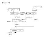
- FIG. 24 is a view illustrating the function of the container security apparatus according to an embodiment of the present invention.
- the container with the container security apparatus may check a transfer path and a sealing state thereof in a process of being transported on a designated path.
- the container security apparatus may transmit a warning against a deviation from the path.
- the release information is transmitted to allow a control room to check in real-time.
- the present invention it is sensed whether a container is opened or not and the sensed opening/closing information is transmitted to a remote location to check whether the container is sealed or not, thereby safely transporting the container to be efficiently used in a transportation field.
Abstract
Description
- The present invention relates to a container security apparatus, and more particularly, to a container security apparatus for safely transporting a container.
- Generally, containers are widely used as means for shipping goods. Particularly, when transporting goods by land from a harbor to an airport, goods are loaded in containers and transported using vehicles.
- Such containers are left as they are in a harbor that is a starting point for a long period or are transported for a long time to a destination in a state of transporting via vehicles. In this case, there occur many robbery cases of goods loaded in containers.
- Robbery cases as described above frequently occur due to structural defects of container security apparatuses. Though there occurs a robbery case, it is hard to be found, which is more fatal.
- General containers include door latch mechanism to lock a door thereof.
- Generally used door latch mechanisms have a problem of being easily opened by drilling bolts of a latch attached to the door. A seal itself may be unsealed using a general cutting device or it is easy to take the seal to pieces by using a duplication thereof.
- On the other hand, electronic seal (eSeal) recently provided is similar to general door seals, identical to door latch mechanisms as a component of a container, and very easily cut off or damaged similar to door latch mechanisms, which makes it impossible to provide safe transportation of containers.
- An aspect of the present invention provides a container security apparatus attached to both opening/closing bars of a container to be detachable to sense whether the container is opened or not and transmitting the sensed opening/closing information to a remote location to check in real time whether the container is sealed or not, thereby safely transporting the container.
- An aspect of the present invention also provides a container security apparatus capable of checking a present location of a container and checking a case when a container deviates from the designated path in real time.
- According to an aspect of the present invention, there is provided a container security apparatus including: a main cover unit with a display part displaying a present state; a main frame coupled with the main cover unit internally, including a first insertion part surrounding one of both opening/closing bars of a container, formed on one side thereof; a first body unit coupled with the main frame internally, including a power-supply part with a built-in battery for supplying power stably mounted thereon; and a sensing part including a guide groove formed penetrating thereinside, a plurality of coupling holes connected to the guide groove, into which a coupling element is inserted, and a sealing sensor whose one end is connected to the coupling element, sensing whether the container is opened or not; a second body unit coupled with the first body unit internally, including an antenna part with a built-in antenna stably mounted thereon; and a board part with a board stably mounted thereon, the board including a sealing module electrically connected to another end of the sealing sensor and transmitting the opening/closing information of the container according to a sensing signal of the sealing sensor, a global positioning system (GPS) module sensing a present location of the container in real-time and transmitting the location information, a communication module transmitting the opening/closing information and the location information to an administration server in real-time, and a control module transmitting the opening/closing information and the location information to the communication module and controlling the sealing module, the GPS module, and the communication module; and a lock frame including a second insertion part surrounding another opening/closing bar of the container and fastened thereto, flat plates connected to both ends of the second insertion part in a single body, a detachable plate connected to one of the flat plates in a single body, with a plurality of detachable holes formed thereon corresponding to the coupling holes, and slidably inserted into the guide groove of the sensing part and coupled with the sensing part by a coupling element, and wire whose one end is connected to an input detachable hole of the detachable holes and other end is connected to an output detachable hole thereof, wherein sealing maintenance information is transmitted when a current circulating the lock frame is input/output to/from the sealing module electrically connected to the sealing sensor, and wherein release information is transmitted when the lock frame is cut off and there is no current running therethrough.
- Also, the lock frame may include a wire line formed thereinside, where the wire is inserted in and fastened thereto.
- Also, the lock frame may include a wire groove formed thereinside, where the wire passes through and is fastened thereto.
- Also, the lock frame may be formed of stainless steel.
- Also, the flat plates may include: a first flat plate connected between one end of the second insertion part and the detachable plate in a single body; and a second flat plate connected to another end of the second insertion part in a single body, wherein the wire is continuously formed from the detachable plate to the second flat plate.
- Also, on inner circumferential surfaces of the input detachable hole and the output detachable hole, there may be provided conductive elements, respectively, electrically connected to the coupling element.
- Also, the communication module may be formed of one of code division multiple access (CDMA), wideband code division multiple access (WCDMA), wireless broadband Internet (WiBro), wireless fidelity (WiFi), and global system/standard for mobile communication (GSM) module.
- Also, the board may further include a database (DB) module for storing container information such as a transfer path, a number, and a license plate number of the container.
- Also, the board may further include a warning module generating and transmitting an alarm signal when the container is deviated from a transfer path thereof or sealing of the container is illegally released.
- Also, the apparatus may further include, when the alarm signal is generated, function of resetting data stored when illegally opening the container, arbitrarily operating the container, or turning off the power of the container.
- Also, the warning module may generate and transmit the alarm signal when a present charge capacity of the built-in battery is 25% or less of a maximum charge capacity thereof.
- Also, the insertion part may include: a sub frame connected to one end of the main frame in a single body and surrounding the opening/closing bar; a compression controller including a shaft whose both ends are fastened to the sub frame externally, a compression cam rotation on an axis of the shaft, and an opening/closing handle connected to the compression cam in a single body; a tightening element installed inside the sub frame and transferred toward the opening/closing bar by a pressure applied by the compression cam; a spring section installed on both sides of the shaft and connected from the outside of the sub frame to a top of the tightening element; and a buffering element installed inside between the tightening element and the sub frame and relieving an impact with the opening/closing bar and improving a grip force.
- Also, the spring section may include: a plurality of vertical supporters whose one end is vertically connected to the tightening element; a plurality of springs provided surrounding the outside of the vertical supporters; and a spring stopper provided on other ends of the vertical supporters and connecting the plurality of vertical supporters.
- Also, inside the second insertion part, there may be provided a buffering element relieving an impact with the opening/closing bar and improving a grip force.
- Also, the buffering element may be formed of a material capable of improving the grip force by strengthening a frictional force such as rubber.
- Also, the power-supply part may include a power-supply switch formed on one side thereof, the power-supply switch turned on when the lock frame is coupled with the sensing part and turned off when the lock frame is detached from the sensing part.
- Also, the power-supply part may turn on the power when the lock frame is coupled with the sensing part and the opening/closing handle is pressurized and may turn off the power when the lock frame is detached from the sensing part and the opening/closing handle is relieved.
- Also, the power-supply part may include a battery port for electrically charging the built-in battery.
- Also, the coupling element may be formed of one of a pin, a bolt, and a switch.
- Also, the display part may display a state whether the power is turned on or off, a state of a residual amount of the battery, a communication state, and a sealed state.
- Also, the main cover unit may include a sub cover part covering the coupling element and preventing malfunction of the coupling element.
- As described above, the container security apparatus according to an embodiment of the present invention provides an effect of safely transporting the container by easily attaching/detaching the apparatus to/from both opening/closing bars of a container, sensing whether the container is opened or not, transmitting opening/closing information to a remote location, and checking whether the container is sealed or not in real-time.
- Also, the apparatus provides an effect of checking in real-time a location of the container and whether the container is deviated from a transfer path thereof.
- Also, the apparatus provides an effect of being applied to not only container vehicles but also various vehicles transferred maintaining security thereof such as refrigerator vehicles.
-
-
FIG. 1 is a front view illustrating a container security apparatus according to an embodiment of the present invention; -
FIG. 2 is a rear view illustrating the container security apparatus ofFIG. 1 ; -
FIG. 3 is a left-side view illustrating the container security apparatus ofFIG. 1 ; -
FIG. 4 is a right-side view illustrating the container security apparatus ofFIG. 1 ; -
FIG. 5 is a top view illustrating the container security apparatus ofFIG. 1 ; -
FIG. 6 is a bottom view illustrating the container security apparatus ofFIG. 1 ; -
FIG. 7 is a schematic perspective view illustrating the container security apparatus ofFIG. 1 ; -
FIG. 8 is a configuration view illustrating a main cover unit of the container security apparatus according to an embodiment of the present invention; -
FIG. 9 is a configuration view illustrating a main frame of the container security apparatus according to an embodiment of the present invention; -
FIG. 10 is a configuration view illustrating a first body unit of the container security apparatus according to an embodiment of the present invention; -
FIG. 11 is a configuration view illustrating a second body unit of the container security apparatus according to an embodiment of the present invention; -
FIGs. 12 and13 are configuration views illustrating a lock frame of the container security apparatus according to an embodiment of the present invention; -
FIG. 14 is a cross-sectional view illustrating the lock frame coupled with a sensing part according to an embodiment of the present invention; -
FIG. 15 is a partial top view illustrating a detachable plate according to an embodiment of the present invention; -
FIGs. 16 and 17 are block views illustrating a board according to an embodiment of the present invention; -
FIG. 18 is a view illustrating an opening/closing bar fastened to the first insertion part according to an embodiment of the present invention; -
FIG. 19 is a view illustrating an operation of fastening the opening/closing bar to the first insertion part according to the present invention; -
FIG. 20 is a view illustrating the opening/closing bar fastened to the second insertion part according to an embodiment of the present invention; -
FIG. 21 is a view illustrating an operation of turning on or off a power-supply switch according to an embodiment of the present invention; -
FIG. 22 is a circuit configuration diagram illustrating a sealing module of the board according to an embodiment of the present invention; -
FIG. 23 is a block diagram illustrating an operation of resetting sealing of the container security apparatus according to an embodiment of the present invention; -
FIG. 24 is a view illustrating the function of the container security apparatus according to an embodiment of the present invention. -
100: MAIN COVER UNIT 110: DISPLAY PART 120: SUB COVER PART 200: MAIN FRAME 300: FIRST BODY UNIT 310: POWER-SUPPLY PART 311: BUILT-IN BATTERY 312: POWER-SUPPLY SWITCH 320: SENSING PART 321: GUIDE GROOVE 322: COUPLING HOLE 323: COUPLING ELEMENT 324: SEALING SENSOR 400: SECOND BODY UNIT 410: ANTENNA PART 420: BOARD PART 430: BOARD 431: SEALING MODULE 432: GPS MODULE 433: COMMUNICATION MODULE 434: DB MODULE 435: WARNING MODULE 436: CONTROL MODULE 500: FIRST INSERTION PART 510: SUB FRAME 520: COMPRESSION CONTROLLER 521: SHAFT 522: COMPRESSION CAM 523: OPENING/CLOSING HANDLE 530: TIGHTENING ELEMENT 540: SPRING SECTION 541: VERTICAL SUPPORTER 542: SPRING STOPPER 543: SPRING 550 & 611: BUFFERING ELEMENTS 600: LOCK FRAME 610: SECOND INSERTION PART 620: FLAT PLATE 621: FIRST FLAT PLATE 622: SECOND FLAT PLATE 630: DETACHABLE PLATE 631: DETACHABLE HOLE 631a: INPUT DETACHABLE HOLE 631b: OUTPUT DETACHABLE HOLE 632: CONDUCTIVE ELEMENT 640: WIRE 700: OPENING/CLOSING BAR - Hereinafter, exemplary embodiments of the present invention will now be described in detail with reference to the attached drawings. It should be noted that the same elements or components have the same reference numerals. While describing the present invention, a detailed description on well-known art or configurations will be omitted not to make the substance of the present invention equivocal.
-
FIG. 1 is a front view illustrating a container security apparatus according to an embodiment of the present invention;FIG. 2 is a rear view illustrating the container security apparatus ofFIG. 1; and FIG. 3 is a left-side view illustrating the container security apparatus ofFIG. 1 . Also,FIG. 4 is a right-side view illustrating the container security apparatus ofFIG. 1 ;FIG. 5 is a top view illustrating the container security apparatus ofFIG. 1 ; andFIG. 6 is a bottom view illustrating the container security apparatus ofFIG. 1 . In addition,FIG. 7 is a schematic perspective view illustrating the container security apparatus ofFIG. 1 ; - The container security apparatus includes, as shown in
FIGs. 1 to 7 , amain cover unit 100, amain frame 200, afirst body unit 300, asecond body unit 400, and alock frame 600. -
FIG. 8 is a configuration view illustrating themain cover unit 100 of the container security apparatus according to an embodiment of the present invention. - Referring to
FIGs. 1 to 6 and8 , themain cover unit 100 is coupled with themain frame 200 externally, covers themain frame 200 and afirst insertion part 500 that will be described later, and includes adisplay part 110 and asub cover part 120. Thedisplay part 110 displays a present state of the container security apparatus. - The
sub cover part 120 covers acoupling element 323 passing through and coupled with themain cover unit 100, which will be described later, and prevents the malfunction of thecoupling element 323. -
FIG. 9 is a configuration view illustrating themain frame 200 of the container security apparatus according to an embodiment of the present invention. - Referring to
FIGs. 7 and9 , themain frame 200 is coupled with themain cover unit 100 internally and equipped with thefirst insertion part 500 covering and fastened to one of both opening/closing bars of a container on one side thereof. -
FIG. 18 is a view illustrating the opening/closing bar 700 fastened to thefirst insertion part 500 according to an embodiment of the present invention, andFIG. 19 is a view illustrating an operation of fastening the opening/closing bar 700 to thefirst insertion part 500 according to the present invention. - Referring to
FIGs. 18 and 19 , thefirst insertion part 500 includes asub frame 510, acompression controller 520, a tighteningelement 530, aspring section 540, and abuffering element 550. - The
sub frame 510 is connected to one side of themain frame 200 in a single body and may surround and support the opening/closing bar 700 externally. - The
compression controller 520 may perform one of fastening the opening/closing bar 700 to thefirst insertion part 500 and separating the opening/closing bar 700 from thefirst insertion part 500, as shown inFIGs. 4 and18 , may include ashaft 521, acompression cam 522, and an opening/closing handle 523. - The tightening
element 530 is installed inside thesub frame 510 and transfers toward the opening/closing bar 700 due to a pressure of thecompression cam 520, and may be closely attached to the opening/closing bar 700. - Referring to
FIG. 18 , thespring section 540 is installed on both sides of theshaft 521, may be connected from the outside of thesub frame 510 to a top of the tighteningelement 530, and may restore the tighteningelement 530 to an original location thereof when the opening/closing handle 523 is rotationally transferred from a bottom to a top to release the pressure of thecompression cam 522 toward the tighteningelement 530. - The
buffering element 550 is provided inside between the tighteningelement 530 and thesub frame 510 to buffer an impact between the tighteningelement 530 and the opening/closing bar 700 and may improve grip thereof. -
FIG. 10 is a configuration view illustrating thefirst body unit 300 of the container security apparatus according to an embodiment of the present invention, andFIG. 21 is a view illustrating an operation of turning on or off a power-supply switch 312 according to an embodiment of the present invention. - The
first body unit 300 is coupled with themain frame 200 internally and includes, as shown inFIG. 10 , a power-supply part 310 and asensing part 320. - Referring to
FIG. 21 , the power-supply part 310 includes a built-inbattery 311 stably mounted thereon to apply power and the power-supply switch 312 turned on when thelock frame 600 is coupled with thesensing part 320 and turned off when thelock frame 600 is detached from thesensing part 320 and simultaneously, the compression of the opening/closing handle 523 is released to separate the opening/closing bar 700 from thefirst insertion part 500. -
FIG. 14 is a cross-sectional view illustrating thelock frame 600 coupled with thesensing part 320 according to an embodiment of the present invention. Thesensing part 320 includes, as shown inFIG. 14 , aguide groove 321, a plurality of coupling holes 322, and a sealingsensor 324. -
FIG. 11 is a configuration view illustrating thesecond body unit 400 of the container security apparatus according to an embodiment of the present invention. - The
second body unit 400 is coupled with thefirst body unit 300 internally and includes, as shown inFIG. 11 , anantenna part 410 and aboard part 420. - The
antenna part 410 includes a built-in antenna stably mounted thereon. -
FIGS. 16 and 17 are block views illustrating aboard 430 according to an embodiment of the present invention. - The
board part 420 includes theboard 430 stably mounted thereon, and theboard 430 includes, as shown inFIG. 16 , asealing module 431, a global positioning system (GPS)module 432, acommunication module 433, and acontrol module 436. -
FIGs. 12 and13 are configuration views illustrating thelock frame 600 of the container security apparatus according to an embodiment of the present invention. - The
lock frame 600 may be formed of stainless steel and includes, as shown inFIGS. 12 and13 , asecond insertion part 610, flat plates 620, adetachable plate 630, and awire 640. -
FIG. 20 is a view illustrating the opening/closing bar 700 fastened to thesecond insertion part 610 according to an embodiment of the present invention. - The
second insertion part 610 surrounds another opening/closing bar 700 of the container and is fastened thereto as shown inFIG. 20 . - The flat plate is, as shown in
FIGs. 12 and13 , connected to both ends of thesecond insertion part 610 in a single body. -
FIG. 15 is a partial top view illustrating thedetachable plate 630 according to an embodiment of the present invention. - The
detachable plate 630 is, as shown inFIG. 15 , connected to one of two flat plates 620, for example, a firstflat plate 621 and includes a plurality ofdetachable holes 631 corresponding to coupling holes 322. - The
detachable plate 630 is slidably inserted into theguide groove 321 in such a way that thedetachable hole 631 corresponds to a location of thecoupling hole 322 and is coupled with thesensing part 320 by thecoupling element 323. - The
wire 640 includes, as shown inFIGs. 12 and13 , one end connected an inputdetachable hole 631a and another end connected to an output detachable hole 631b and is provided from thedetachable plate 630 to the secondflat plate 622. - Hereinafter, exemplary embodiments of the present invention will now be described in detail with reference to the attached drawings. It should be noted that the same elements or components have the same reference numerals. While describing the present invention, a detailed description on well-known art or configurations will be omitted not to make the substance of the present invention equivocal.
-
FIG. 1 is a front view illustrating a container security apparatus according to an embodiment of the present invention;FIG. 2 is a rear view illustrating the container security apparatus ofFIG. 1; and FIG. 3 is a left-side view illustrating the container security apparatus ofFIG. 1 . Also,FIG. 4 is a right-side view illustrating the container security apparatus ofFIG. 1 ;FIG. 5 is a top view illustrating the container security apparatus ofFIG. 1 ; andFIG. 6 is a bottom view illustrating the container security apparatus ofFIG. 1 . In addition,FIG. 7 is a schematic perspective view illustrating the container security apparatus ofFIG. 1 ; - The container security apparatus includes, as shown in
FIGs. 1 to 7 , amain cover unit 100, amain frame 200, afirst body unit 300, asecond body unit 400, and alock frame 600. -
FIG. 8 is a configuration view illustrating themain cover unit 100 of the container security apparatus according to an embodiment of the present invention. - Referring to
FIGs. 1 to 6 and8 , themain cover unit 100 is coupled with themain frame 200 externally, covers themain frame 200 and afirst insertion part 500 that will be described later, and includes adisplay part 110 and asub cover part 120. Thedisplay part 110 displays a present state of the container security apparatus. - In detail, the
display part 110 may be formed of one of a liquid crystal display (LCD) and a light-emitting diode (LED) and may display the present status of the container security apparatus such as the status of turning the container security apparatus on/off, the status of a residual quantity of a battery, a status of communication, and a status of sealing. - The
sub cover part 120 covers acoupling element 323 passing through and coupled with themain cover unit 100, which will be described later, and prevents the malfunction of thecoupling element 323. - In detail, the
sub cover part 120 may open or shut thecoupling element 323 by slidably transferring on themain cover unit 100 or by using a hinge. -
FIG. 9 is a configuration view illustrating themain frame 200 of the container security apparatus according to an embodiment of the present invention. - Referring to
FIGs. 7 and9 , themain frame 200 is coupled with themain cover unit 100 internally and equipped with thefirst insertion part 500 covering and fastened to one of both opening/closing bars of a container on one side thereof. -
FIG. 18 is a view illustrating the opening/closing bar 700 fastened to thefirst insertion part 500 according to an embodiment of the present invention, andFIG. 19 is a view illustrating an operation of fastening the opening/closing bar 700 to thefirst insertion part 500 according to the present invention. - Referring to
FIGs. 18 and 19 , thefirst insertion part 500 includes asub frame 510, acompression controller 520, a tighteningelement 530, aspring section 540, and abuffering element 550. - The
sub frame 510 is connected to one side of themain frame 200 in a single body and may surround and support the opening/closing bar 700 externally. - The
sub frame 510 may be formed in various shapes, and more particularly, a shape of "⊂" in the present embodiment. - The
compression controller 520 may perform one of fastening the opening/closing bar 700 to thefirst insertion part 500 and separating the opening/closing bar 700 from thefirst insertion part 500, as shown inFIGs. 4 and18 , may include ashaft 521, acompression cam 522, and an opening/closing handle 523. - The
shaft 521 passes through a hollow portion of thecompression cam 522 and both ends thereof are fastened to the outside of thesub frame 510. - The
compression cam 522 is formed in a rectangular shape whose one set of sides are longer than another set of sides and is rotationally transferred on an axis of theshaft 521. - The opening/
closing handle 523 is formed in a parabolic shape with a fluent curve portion formed thereon and is connected to thecompression cam 522 in a single body, thereby transferring a rotational force to thecompression cam 522. - In detail, as shown in
FIG. 19 , the opening/closing handle 523 is rotationally transferred from a top to a bottom in such a way that thecompression cam 522 simultaneously rotates on an axis of theshaft 521 and the tighteningelement 530 is compressed. - The tightening
element 530 is installed inside thesub frame 510 and transfers toward the opening/closing bar 700 due to a pressure of thecompression cam 520, and may be closely attached to the opening/closing bar 700. - Referring to
FIG. 18 , thespring section 540 is installed on both sides of theshaft 521, may be connected from the outside of thesub frame 510 to a top of the tighteningelement 530, and may restore the tighteningelement 530 to an original location thereof when the opening/closing handle 523 is rotationally transferred from a bottom to a top to release the pressure of thecompression cam 522 toward the tighteningelement 530. - In detail, the
spring section 540 includes, as shown inFIG. 18 , a plurality ofvertical supporters 541, a plurality ofsprings 543, and aspring stopper 542. - The
vertical supporter 541 includes one end connected vertically to the tighteningelement 530 and another end projected outside thesub frame 510, thereby supporting the tighteningelement 530. - The
spring 543 is provided surrounding the outside of thevertical supporter 541 and may generate a restoring force to the tighteningelement 530 depending on contraction and relaxation thereof. - The
spring stopper 542 may be provided to the other ends of thevertical supporters 541 to connect the plurality ofvertical supporters 541 to one another and may generate an elasticity force to thespring 543 by contracting thespring 543 when thecompression cam 522 compresses the tighteningelement 530. - The
buffering element 550 is provided inside between the tighteningelement 530 and thesub frame 510 to buffer an impact between the tighteningelement 530 and the opening/closing bar 700 and may improve grip thereof. - In detail, the opening/
closing bar 700 is closely attached and fastened to thebuffering element 550 transferred by thecompression controller 520, whose impact is relieved by thebuffering element 550 provided inside between the tighteningelement 530 and thesub frame 510, thereby being fastened while improving grip thereof. In this case, thebuffering element 550 may be formed of a material capable of improving a grip force by strengthening a frictional force such as rubber. -
FIG. 10 is a configuration view illustrating thefirst body unit 300 of the container security apparatus according to an embodiment of the present invention, andFIG. 21 is a view illustrating an operation of turning on or off a power-supply switch 312 according to an embodiment of the present invention. - The
first body unit 300 is coupled with themain frame 200 internally and includes, as shown inFIG. 10 , a power-supply part 310 and asensing part 320. - Referring to
FIG. 21 , the power-supply part 310 includes a built-inbattery 311 stably mounted thereon to apply power and the power-supply switch 312 turned on when thelock frame 600 is coupled with thesensing part 320 and turned off when thelock frame 600 is detached from thesensing part 320. - In detail, the power-
supply switch 312 may be pressed by a pressure applied by thedetachable plate 630 and turn power on when thedetachable plate 630 of thelock frame 600, which will be described later, is coupled with thesensing part 320 and may return to an original location thereon and turn the power off due to a removal of the pressure applied by thedetachable plate 630 when thedetachable plate 630 is detached from thesensing part 320. - In this case, the power-
supply part 310 may include a battery port, not shown, to electrically charge the built-inbattery 311, which may be formed of 8-celled nickel-hydro battery. - On the other hand, the power-
supply part 310 may be formed to turn the power on when thelock frame 600 is coupled with thesensing part 320 and simultaneously, the opening/closing handle 523 of thecompression controller 520 is compressed and fastens the opening/closing bar 700 to thefirst insertion part 500 and to turn the power off when thelock frame 600 is detached from thesensing part 320 -
FIG. 14 is a cross-sectional view illustrating thelock frame 600 coupled with thesensing part 320 according to an embodiment of the present invention. Thesensing part 320 includes, as shown inFIG. 14 , aguide groove 321, a plurality of coupling holes 322, and a sealingsensor 324. - The
guide groove 321 may be formed to pass through inside thesensing part 320, into which the lock frame may be slidably inserted. - The
coupling hole 322 is connected to theguide groove 321, the coupling hole in which thecoupling element 323 may be inserted. In this case, thecoupling element 323 may be formed of one of a pin, a bolt, and a switch. - The sealing
sensor 324 includes one end connected to thecoupling element 323 and other end electrically connected to asealing module 431 of theboard 430, which will be described later, when thecoupling element 323 is inserted into thecoupling hole 322, thereby sensing whether the container is open or closed. -
FIG. 11 is a configuration view illustrating thesecond body unit 400 of the container security apparatus according to an embodiment of the present invention. - The
second body unit 400 is coupled with thefirst body unit 300 internally and includes, as shown inFIG. 11 , anantenna part 410 and aboard part 420. - The
antenna part 410 includes a built-in antenna stably mounted thereon. -
FIGs. 16 and 17 are block views illustrating aboard 430 according to an embodiment of the present invention. - The
board part 420 includes theboard 430 stably mounted thereon, and theboard 430 includes, as shown inFIG. 16 , asealing module 431, a global positioning system (GPS)module 432, acommunication module 433, and acontrol module 436. - The
sealing module 431 is electrically connected to another end of the sealingsensor 324 and transmits information on whether the container is opened or not according to a sensing signal of the sealingsensor 324 to thecontrol module 436. - When a current circulating the
lock frame 600 is input/output to/from thesealing module 431 electrically connected to the sealingsensor 324, it is considered as a sealed state and sealing maintenance information may be transmitted to thecontrol module 436. When thelock frame 600 is cut off and a current is not applied, it is considered as a release state and release information may be transmitted to thecontrol module 436. -
FIG. 22 is a circuit diagram illustrating thesealing module 431 of theboard 430 according to an embodiment of the present invention. - In detail, when the sealing
sensor 324 is electrically connected to aNODE 2 shown inFIG. 22 , since a contact point is in contact, a GPIO signal of a central processing unit (CPU) may become HIGH. When the sealingsensor 324 is not electrically connected to theNODE 2, since the contact point is shortcircuited, the GPIO signal of the CPU may become LOW. - In this case, the sealing maintenance information may be transmitted when the GPIO signal is HIGH and it is considered as the sealed state, and the release information may be transmitted when the GPIO signal is LOW and it is considered as the release state.
- The
GPS module 432 senses a real-time location of the container and transmits the location information thereof to thecontrol module 436. - The
GPS module 432 may be connected to thecontrol module 436 using a serial interface, may be modulated by applying location information analysis application via universal asynchronous receiver transmitter (UART), and may transmit the location information to thecontrol module 436 periodically, for example, every one minute. - The
communication module 433 receives the opening/closing information and the location information from thecontrol module 436 and transmits the same to an administration server. - The
communication module 433 may be connected to thecontrol module 436 using a serial interface, may be modulated by applying an Internet communication application via UART such as transmission control protocol/Internet protocol (TCP/IP), and may transmit the opening/closing information and the location information to the administration server via Internet. - In this case, the
communication module 433 may be formed of one of code division multiple access (CDMA), wideband code division multiple access (WCDMA), wireless broadband Internet (WiBro), wireless fidelity (WiFi), and global system/standard for mobile communication (GSM) module. - The
control module 436 receives the opening/closing information and the location information, transmits the same to thecommunication module 433, and controls thesealing module 431, theGPS module 432, and thecommunication module 433. - On the other hand, the
board 430 may further include a database (DB)module 434 and awarning module 435, as shown inFIG. 17 . - The
DB module 434 is controlled by thecontrol module 436 and stores information on the container, such as a transfer path thereof, the number of the container, a license plate number of the container. - The
warning module 435 is controlled by thecontrol module 436 and generates and transmits an alarm signal to thecontrol module 436 when the container is deviated from a transfer path thereof stored in theDB module 434 or sealing of the container is released and thesealing module 431 transmits the release information to thecontrol module 436. - In this case, the alarm signal is transmitted from the
control module 436 to thecommunication module 433 and may be transmitted to the administration server in real-time via thecommunication module 433. - Also, the
warning module 435 may generate and transmit an alarm signal to thecontrol module 436 when a present charge capacity of the built-in battery is 25% or less of a maximum charge capacity thereof. -
FIGs. 12 and13 are configuration views illustrating thelock frame 600 of the container security apparatus according to an embodiment of the present invention. - The
lock frame 600 may be formed of stainless steel and includes, as shown inFIGs. 12 and13 , asecond insertion part 610, flat plates, adetachable plate 630, and awire 640. -
FIG. 20 is a view illustrating the opening/closing bar 700 fastened to thesecond insertion part 610 according to an embodiment of the present invention. - The
second insertion part 610 surrounds another opening/closing bar 700 of the container and is fastened thereto as shown inFIG. 20 . - In detail, the
second insertion part 610 may be formed in a U shape with a fluent curved portion, inside which abuffering element 611 is provided, in such a way that an impact between thesecond insertion part 610 and the opening/closing bar is relieved and a grip force may be improved. In this case, thebuffering element 611 may be formed of a material capable of improving the grip force by strengthening a frictional force such as rubber. - The flat plate is connected to both ends of the
second insertion part 610 in a single body as shown inFIGs. 12 and13 . - In detail, the flat plate may include a first
flat plate 621 connected between one end of thesecond insertion part 610 and thedetachable plate 630 in a single body and a secondflat plate 622 connected to the firstflat plate 621 and another end of thesecond insertion part 610 in a single body. -
FIG. 15 is a partial top view illustrating thedetachable plate 630 according to an embodiment of the present invention. - The
detachable plate 630 is, as shown inFIG. 15 , connected to one of two flat plates 620, for example, the firstflat plate 621 and includes a plurality ofdetachable holes 631 corresponding to coupling holes 322. - The
detachable plate 630 is slidably inserted into theguide groove 321 in such a way that thedetachable hole 631 corresponds to a location of thecoupling hole 322 and is coupled with thesensing part 320 by thecoupling element 323. - The
wire 640 includes, as shown inFIGs. 12 and13 , one end connected an inputdetachable hole 631a and another end connected to an output detachable hole 631b and is provided from thedetachable plate 630 to the secondflat plate 622. - In detail, the
wire 640 is continuously formed inside a top of thelock frame 600 from thedetachable plate 630 to the secondflat plate 622, from a top to a bottom of the secondflat plate 622, and inside a bottom of thelock frame 600 from the secondflat plate 622 to thedetachable plate 630 in such a way that one end thereof may be connected to the inputdetachable hole 631a and another end thereof may be connected to the output detachable hole 631b. - Accordingly, the
wire 640 is connected to thecoupling element 323 inserted in thedetachable hole 631, thereby being electrically connected to thesealing module 431 of theboard 430 via the sealingsensor 324 connected to thecoupling element 323. - On the other hand, the
lock frame 600 may include, as shown inFIG. 12 , a wire line formed in a semicircular groove shape therein, into which thewire 640 is inserted, in such a way that thewire 640 is fastened to thelock frame 600. - Also, the
lock frame 600 may include, as shown inFIG. 13 , a wire groove formed in a circular groove therein, through which thewire 640 passes, in such a way that thewire 640 is fastened to thelock frame 600. - In this case, the wire line and the wire groove may be formed continuously from the
detachable plate 630 to the secondflat plate 622. - On the other hand, as shown in
FIG. 15 , on inner circumferential surfaces of the inputdetachable hole 631a and the output detachable hole 631b, there may be providedconductive elements 632 electrically connected to thecoupling element 323 inserted in thesensing part 320. - Accordingly, the
wire 640 provided in thelock frame 600 may be electrically connected to thesealing module 431 of theboard 430 via theconductive element 632, thecoupling element 323 inserted in thedetachable hole 631, and the sealingsensor 324 connected to thecoupling element 323. - On the other hand, the container security apparatus according to an embodiment of the present invention may generate an alarm signal by storing data on an illegal opening when illegally opening the container and storing data on situations such as arbitrarily operations and turning off the power.
- In this case, when the alarm signal is continuously generated, it is difficult to reuse the container security apparatus. For this, stored data of the container security apparatus may be reset to initialize the container security apparatus.
-
FIG. 23 is a block diagram illustrating an operation of resetting sealing of the container security apparatus according to an embodiment of the present invention. - The container security apparatus checks the status of the stored data together with booting when power is turned off.
- In this case, the check on the status of the stored data may be performed on electrically erasable programmable read-only memory (EEPROM), which is a part of nonvolatile memory, capable of changing a state thereof by using an electric signal.
- In detail, when a state of EEPROM (hereinafter, referred to as E.S.) is 0, there is indicated a state of being reset after approval, when E.S. is 1, there is indicated a state of electrical sealing, when E.S. is 2, there is indicated a state of one of containing an illegal opening record and a record of arbitrarily turning off the power and generating an alarm signal.
- Accordingly, as shown in
FIG. 23 , when the power is turned on, a present E. S may become 0 if a previous E.S. is 0, a present E.S. may become 2 if the previous E.S. is 1, and a present E.S. may become 2 if the previous E.S. is 2. - On the contrary, when normally approved, a present E.S. is changed into 0 if a previous E.S is 0, a present E.S. is changed into 0 if a previous E.S. is 1, and a present E.S. is changed into 0 if a previous E.S. is 2. As described above, the container security apparatus is initialized as a reset state, thereby reusing the container security apparatus.
-
FIG. 24 is a view illustrating the function of the container security apparatus according to an embodiment of the present invention. - As described above, as shown in
FIG. 24 , the container with the container security apparatus according to an embodiment of the present invention attached thereon may check a transfer path and a sealing state thereof in a process of being transported on a designated path. When the container deviates from the designated path, the container security apparatus may transmit a warning against a deviation from the path. Also, when the container is illegally opened, the release information is transmitted to allow a control room to check in real-time. - While the present invention has been particularly shown and described with reference to exemplary embodiments thereof, it will be understood by those skilled in the art that various changes in form and details may be made therein without departing from the spirit and scope of the invention as defined by the appended claims.
- According to the present invention, it is sensed whether a container is opened or not and the sensed opening/closing information is transmitted to a remote location to check whether the container is sealed or not, thereby safely transporting the container to be efficiently used in a transportation field.
Claims (21)
- A container security apparatus comprising:a main cover unit with a display part displaying a present state;a main frame coupled with the main cover unit internally, comprising a first insertion part surrounding one of both opening/closing bars of a container, formed on one side thereof;a first body unit coupled with the main frame internally, comprising a power-supply part with a built-in battery for supplying power stably mounted thereon; and a sensing part comprising a guide groove formed penetrating thereinside, a plurality of coupling holes connected to the guide groove, into which a coupling element is inserted, and a sealing sensor whose one end is connected to the coupling element, sensing whether the container is opened or not;a second body unit coupled with the first body unit internally, comprising an antenna part with a built-in antenna stably mounted thereon; and a board part with a board stably mounted thereon, the board comprising a sealing module electrically connected to another end of the sealing sensor and transmitting the opening/closing information of the container according to a sensing signal of the sealing sensor, a global positioning system (GPS) module sensing a present location of the container in real-time and transmitting the location information, a communication module transmitting the opening/closing information and the location information to an administration server in real-time, and a control module transmitting the opening/closing information and the location information to the communication module and controlling the sealing module, the GPS module, and the communication module; anda lock frame comprising a second insertion part surrounding another opening/closing bar of the container and fastened thereto, flat plates connected to both ends of the second insertion part in a single body, a detachable plate connected to one of the flat plates in a single body, with a plurality of detachable holes formed thereon corresponding to the coupling holes, and slidably inserted into the guide groove of the sensing part and coupled with the sensing part by a coupling element, and wire whose one end is connected to an input detachable hole of the detachable holes and other end is connected to an output detachable hole thereof,wherein sealing maintenance information is transmitted when a current circulating the lock frame is input/output to/from the sealing module electrically connected to the sealing sensor, andwherein the release information is transmitted when the lock frame is cut off and there is no current running therethrough.
- The apparatus of claim 1, wherein the lock frame comprises a wire line formed thereinside, where the wire is inserted in and fastened thereto.
- The apparatus of claim 1, wherein the lock frame comprises a wire groove formed thereinside, where the wire passes through and is fastened thereto.
- The apparatus of claim 1, wherein the lock frame is formed of stainless steel.
- The apparatus of claim 1, wherein the flat plates comprises:a first flat plate connected between one end of the second insertion part and the detachable plate in a single body; anda second flat plate connected to another end of the second insertion part in a single body,wherein the wire is continuously formed from the detachable plate to the second flat plate.
- The apparatus of claim 1, wherein, on inner circumferential surfaces of the input detachable hole and the output detachable hole, there are provided conductive elements, respectively, electrically connected to the coupling element.
- The apparatus of claim 1, wherein the communication module is formed of one of code division multiple access (CDMA), wideband code division multiple access (WCDMA), wireless broadband Internet (WiBro), wireless fidelity (WiFi), and global system/standard for mobile communication (GSM) module.
- The apparatus of claim 1, wherein the board further comprises a database (DB) module for storing container information such as a transfer path, a number, and a license plate number of the container.
- The apparatus of claim 1, wherein the board further comprises a warning module generating and transmitting an alarm signal when the container is deviated from a transfer path thereof or sealing of the container is illegally released.
- The apparatus of claim 9, further comprising, when the alarm signal is generated, function of resetting data stored when illegally opening the container, arbitrarily operating the container, or turning off the power of the container.
- The apparatus of claim 9, wherein the warning module generates and transmits the alarm signal when a present charge capacity of the built-in battery is 25% or less of a maximum charge capacity thereof.
- The apparatus of claim 1, wherein the insertion part comprises:a sub frame connected to one end of the main frame in a single body and surrounding the opening/closing bar;a compression controller comprising a shaft whose both ends are fastened to the sub frame externally, a compression cam rotation on an axis of the shaft, and an opening/closing handle connected to the compression cam in a single body;a tightening element installed inside the sub frame and transferred toward the opening/closing bar by a pressure applied by the compression cam;a spring section installed on both sides of the shaft and connected from the outside of the sub frame to a top of the tightening element; anda buffering element installed inside between the tightening element and the sub frame and relieving an impact with the opening/closing bar and improving a grip force.
- The apparatus of claim 12, wherein the spring section comprises:a plurality of vertical supporters whose one end is vertically connected to the tightening element;a plurality of springs provided surrounding the outside of the vertical supporters; anda spring stopper provided on other ends of the vertical supporters and connecting the plurality of vertical supporters.
- The apparatus of claim 1, wherein inside the second insertion part, there is provided a buffering element relieving an impact with the opening/closing bar and improving a grip force.
- The apparatus according to any one of claims 12 and 14, wherein the buffering element is formed of a material capable of improving the grip force by strengthening a frictional force such as rubber.
- The apparatus of claim 1, wherein the power-supply part comprises a power-supply switch formed on one side thereof, the power-supply switch turned on when the lock frame is coupled with the sensing part and turned off when the lock frame is detached from the sensing part.
- The apparatus of claim 12, wherein the power-supply part turns on the power when the lock frame is coupled with the sensing part and the opening/closing handle is pressurized and turns off the power when the lock frame is detached from the sensing part and the opening/closing handle is relieved.
- The apparatus of claim 1, wherein the power-supply part comprises a battery port for electrically charging the built-in battery.
- The apparatus of claim 1, wherein the coupling element is formed of one of a pin, a bolt, and a switch.
- The apparatus of claim 1, wherein the display part displays a state whether the power is turned on or off, a state of a residual amount of the battery, a communication state, and a sealed state.
- The apparatus of claim 1, wherein the main cover unit comprises a sub cover part covering the coupling element and preventing malfunction of the coupling element.
Applications Claiming Priority (2)
| Application Number | Priority Date | Filing Date | Title |
|---|---|---|---|
| KR1020100021720A KR101175173B1 (en) | 2010-03-11 | 2010-03-11 | Sealing device of a container |
| PCT/KR2011/001547 WO2011111959A2 (en) | 2010-03-11 | 2011-03-07 | Container security apparatus |
Publications (2)
| Publication Number | Publication Date |
|---|---|
| EP2546437A2 true EP2546437A2 (en) | 2013-01-16 |
| EP2546437A4 EP2546437A4 (en) | 2014-06-11 |
Family
ID=44563971
Family Applications (1)
| Application Number | Title | Priority Date | Filing Date |
|---|---|---|---|
| EP20110753564 Withdrawn EP2546437A4 (en) | 2010-03-11 | 2011-03-07 | Container security apparatus |
Country Status (6)
| Country | Link |
|---|---|
| US (1) | US8773262B2 (en) |
| EP (1) | EP2546437A4 (en) |
| JP (1) | JP2013530902A (en) |
| KR (1) | KR101175173B1 (en) |
| CN (1) | CN102869845B (en) |
| WO (1) | WO2011111959A2 (en) |
Families Citing this family (20)
| Publication number | Priority date | Publication date | Assignee | Title |
|---|---|---|---|---|
| KR101331234B1 (en) * | 2011-09-30 | 2013-11-18 | 주식회사 에스엘에스테크 | Container locking rod with monitoring and security function device |
| DE102012201021A1 (en) * | 2012-01-24 | 2013-07-25 | Cargoguard Gmbh | Locking device for closing and securing a receiving device |
| KR101484133B1 (en) | 2013-09-11 | 2015-01-22 | 주식회사 에스위너스 | Sealing Device for Container Door and Method for Operating the Same |
| US10055953B2 (en) * | 2013-09-16 | 2018-08-21 | S-Winnus Co., Ltd. | Device for electronically sealing container using proximity wireless communication, and system and method for operating same |
| KR101738101B1 (en) * | 2014-10-16 | 2017-05-19 | 이지영 | Window Alarm Apparatus |
| KR101660423B1 (en) * | 2015-04-10 | 2016-09-28 | 주식회사 에스위너스 | Apparatus for Sensing Closing and Opening of Container Door for Container Security |
| KR101648828B1 (en) * | 2015-12-07 | 2016-08-17 | 주식회사 포유텍 | Electrical seal system for container door |
| US9997861B2 (en) * | 2015-12-10 | 2018-06-12 | International Business Machines Corporation | Force limiting latch indicator |
| IL307973A (en) | 2016-09-21 | 2023-12-01 | Molecular Imprints Inc | Microlithographic fabrication of structures |
| US20200226954A1 (en) * | 2017-07-07 | 2020-07-16 | Vypin, LLC | Electronic Seal (E-Seal) Device and Related Techniques |
| CN108263773B (en) * | 2018-02-05 | 2020-03-27 | 覃道喜 | Special lock of double insurance container |
| KR102044931B1 (en) * | 2018-11-20 | 2019-11-14 | 주식회사 알티자동화 | Real-time location information management device and method of transportation management system |
| US11481716B2 (en) * | 2020-06-10 | 2022-10-25 | Inlecom Group Bvba | Route auditing for physical internet container routing |
| US20220195766A1 (en) * | 2020-12-18 | 2022-06-23 | In-Tech Enterprise Ltd. | Container locking system |
| BR102021004997B1 (en) * | 2021-03-16 | 2023-11-07 | Lohmm Participacoes S.A. | SET OF CARGO CONTAINERS |
| US11785424B1 (en) | 2021-06-28 | 2023-10-10 | Wm Intellectual Property Holdings, L.L.C. | System and method for asset tracking for waste and recycling containers |
| KR102605588B1 (en) | 2021-11-29 | 2023-11-24 | 동아대학교 산학협력단 | Door Sealing Device for Smart Container And Method for Controlling the Same |
| KR102605584B1 (en) | 2021-12-13 | 2023-11-24 | 동아대학교 산학협력단 | Door Sealing And Sensing System for Smart Container And Method for Controlling the Same |
| KR20230106906A (en) | 2022-01-07 | 2023-07-14 | 임제연 | A container seal using wasted fish net |
| KR20230106899A (en) | 2022-01-07 | 2023-07-14 | 임제연 | A container seal |
Family Cites Families (17)
| Publication number | Priority date | Publication date | Assignee | Title |
|---|---|---|---|---|
| JPH11345374A (en) * | 1998-06-01 | 1999-12-14 | Itoki Crebio Corp | System for locking and unlocking transportation vehicle and its method |
| JP3180086B2 (en) * | 1998-08-31 | 2001-06-25 | 株式会社シーメディア | Mobile communication device, information transmission system and method, non-contact IC media usable in mobile communication device |
| JP2000172812A (en) * | 1998-12-08 | 2000-06-23 | Hitachi Maxell Ltd | Noncontact information medium |
| JP2002211319A (en) * | 2001-01-17 | 2002-07-31 | Yukichi Tamura | Auxiliary gangway for truck deck body |
| JP4862232B2 (en) * | 2001-07-17 | 2012-01-25 | 株式会社Ihi | Container management method and wireless IC seal tag in container terminal |
| US7411495B2 (en) | 2002-08-27 | 2008-08-12 | Hi-G-Tek Ltd. | Smart container monitoring system |
| US7135976B2 (en) * | 2003-03-31 | 2006-11-14 | Rftrax, Inc. | Wireless monitoring device |
| US6870476B2 (en) * | 2003-04-07 | 2005-03-22 | Bulldog Technologies Inc. | Continuous feedback container security system |
| CN2690346Y (en) * | 2003-10-27 | 2005-04-06 | 中国国际海运集装箱(集团)股份有限公司 | Hidden container safety device and container |
| JP2005157780A (en) * | 2003-11-26 | 2005-06-16 | Dainippon Printing Co Ltd | Tag type information recording medium |
| CN2701797Y (en) * | 2004-01-14 | 2005-05-25 | 中国国际海运集装箱(集团)股份有限公司 | Locking apparatus for container safety device and container |
| JP2006143311A (en) * | 2004-11-24 | 2006-06-08 | Yoshihide Soda | Opening confirmation mechanism and home delivery cool container, etc. using the same |
| US20070200701A1 (en) * | 2006-02-27 | 2007-08-30 | English Kent L | Network centric sensor fusion for shipping container security |
| KR20070114483A (en) * | 2006-05-29 | 2007-12-04 | (주)프리비아 | Wireless controllable container doorlock with electronic seal and storing function of the trajectory using gps |
| TW200848592A (en) | 2007-06-12 | 2008-12-16 | Trade Van Information Services Co | Container monitoring system and electrical container lock |
| US8207848B2 (en) | 2008-05-16 | 2012-06-26 | Google Inc. | Locking system for shipping container including bolt seal and electronic device with arms for receiving bolt seal |
| US20100194579A1 (en) * | 2009-02-02 | 2010-08-05 | Dong-A University Industry-University Cooperation Foundation | Container security device, container security system, and security management method |
-
2010
- 2010-03-11 KR KR1020100021720A patent/KR101175173B1/en not_active IP Right Cessation
-
2011
- 2011-03-07 US US13/583,876 patent/US8773262B2/en not_active Expired - Fee Related
- 2011-03-07 EP EP20110753564 patent/EP2546437A4/en not_active Withdrawn
- 2011-03-07 JP JP2012556964A patent/JP2013530902A/en active Pending
- 2011-03-07 WO PCT/KR2011/001547 patent/WO2011111959A2/en active Application Filing
- 2011-03-07 CN CN201180018318.7A patent/CN102869845B/en not_active Expired - Fee Related
Non-Patent Citations (2)
| Title |
|---|
| No further relevant documents disclosed * |
| See also references of WO2011111959A2 * |
Also Published As
| Publication number | Publication date |
|---|---|
| CN102869845B (en) | 2015-08-26 |
| CN102869845A (en) | 2013-01-09 |
| WO2011111959A3 (en) | 2011-12-29 |
| JP2013530902A (en) | 2013-08-01 |
| WO2011111959A2 (en) | 2011-09-15 |
| EP2546437A4 (en) | 2014-06-11 |
| KR101175173B1 (en) | 2012-08-20 |
| US20130000362A1 (en) | 2013-01-03 |
| KR20110102622A (en) | 2011-09-19 |
| US8773262B2 (en) | 2014-07-08 |
Similar Documents
| Publication | Publication Date | Title |
|---|---|---|
| US8773262B2 (en) | Container security apparatus | |
| TWI302269B (en) | Systems, methods and computer program products for monitoring transport containers | |
| CN103282591B (en) | For the state detector of remote tracing padlock and communication unit and system | |
| US5646592A (en) | Anti-theft method for detecting the unauthorized opening of containers and baggage | |
| CN100547619C (en) | Equipment container safety feature and do not use the method and system of electronic reader | |
| US20200226954A1 (en) | Electronic Seal (E-Seal) Device and Related Techniques | |
| US20080231459A1 (en) | Cargo Container Monitoring Device | |
| AU2006214802B2 (en) | A reusable container with radio frequency identification seal | |
| US7218215B2 (en) | Cargo container integrity system | |
| US20030189491A1 (en) | Circuit and method for electronic security seal | |
| KR101560366B1 (en) | Operation System for Container Electronic Sealing Device and Operation Method of the Same | |
| KR101876923B1 (en) | Electronic sealing device for container | |
| CN101529483B (en) | Sensor arrangement for securing the loads of containers | |
| US8149118B2 (en) | Device and method for registering the opening of closures of spaces to be secured | |
| US10055953B2 (en) | Device for electronically sealing container using proximity wireless communication, and system and method for operating same | |
| KR101038415B1 (en) | Vehicle and cargo management system | |
| SE528134C2 (en) | Seal with transponder | |
| CN115023705A (en) | Package comprising radio frequency identification seal | |
| WO2016116903A1 (en) | Security system for goods carriage containers | |
| US9319093B2 (en) | System and method for communicating with an unpowered device | |
| US7579949B2 (en) | Anti-theft system and container safeguarded by the same | |
| KR20150032383A (en) | Operation System for Container Electronic Sealing Device and Operation Method of the Same | |
| JP4781703B2 (en) | Portable container with induction antenna and position detection system | |
| KR20170059770A (en) | Operation System and Method for Container Electronic Sealing Device Using Bluetooth Based on Low Power | |
| CN102913068B (en) | Electronic seal lock |
Legal Events
| Date | Code | Title | Description |
|---|---|---|---|
| PUAI | Public reference made under article 153(3) epc to a published international application that has entered the european phase |
Free format text: ORIGINAL CODE: 0009012 |
|
| 17P | Request for examination filed |
Effective date: 20121011 |
|
| AK | Designated contracting states |
Kind code of ref document: A2 Designated state(s): AL AT BE BG CH CY CZ DE DK EE ES FI FR GB GR HR HU IE IS IT LI LT LU LV MC MK MT NL NO PL PT RO RS SE SI SK SM TR |
|
| DAX | Request for extension of the european patent (deleted) | ||
| A4 | Supplementary search report drawn up and despatched |
Effective date: 20140512 |
|
| RIC1 | Information provided on ipc code assigned before grant |
Ipc: E05B 45/00 20060101ALN20140506BHEP Ipc: E05B 83/10 20140101ALI20140506BHEP Ipc: E05C 19/18 20060101ALI20140506BHEP Ipc: E05B 17/22 20060101ALN20140506BHEP Ipc: E05B 39/00 20060101AFI20140506BHEP Ipc: E05B 45/06 20060101ALI20140506BHEP |
|
| RIC1 | Information provided on ipc code assigned before grant |
Ipc: E05B 83/10 20140101ALI20150323BHEP Ipc: E05B 17/22 20060101ALN20150323BHEP Ipc: E05C 19/18 20060101ALI20150323BHEP Ipc: E05B 45/06 20060101ALI20150323BHEP Ipc: E05B 39/00 20060101AFI20150323BHEP Ipc: E05B 45/00 20060101ALN20150323BHEP |
|
| GRAP | Despatch of communication of intention to grant a patent |
Free format text: ORIGINAL CODE: EPIDOSNIGR1 |
|
| INTG | Intention to grant announced |
Effective date: 20150528 |
|
| STAA | Information on the status of an ep patent application or granted ep patent |
Free format text: STATUS: THE APPLICATION IS DEEMED TO BE WITHDRAWN |
|
| 18D | Application deemed to be withdrawn |
Effective date: 20151008 |