EP2546094B1 - System, device and method for exchanging energy with an electric vehicle - Google Patents
System, device and method for exchanging energy with an electric vehicle Download PDFInfo
- Publication number
- EP2546094B1 EP2546094B1 EP12187206.3A EP12187206A EP2546094B1 EP 2546094 B1 EP2546094 B1 EP 2546094B1 EP 12187206 A EP12187206 A EP 12187206A EP 2546094 B1 EP2546094 B1 EP 2546094B1
- Authority
- EP
- European Patent Office
- Prior art keywords
- energy
- vehicle
- port
- energy exchange
- exchanging
- Prior art date
- Legal status (The legal status is an assumption and is not a legal conclusion. Google has not performed a legal analysis and makes no representation as to the accuracy of the status listed.)
- Active
Links
- 238000000034 method Methods 0.000 title claims description 6
- 238000012545 processing Methods 0.000 claims description 77
- 238000004891 communication Methods 0.000 claims description 41
- 230000008878 coupling Effects 0.000 claims description 8
- 238000010168 coupling process Methods 0.000 claims description 8
- 238000005859 coupling reaction Methods 0.000 claims description 8
- 239000011159 matrix material Substances 0.000 claims description 7
- 238000012360 testing method Methods 0.000 claims description 6
- 230000008569 process Effects 0.000 claims description 2
- 238000007726 management method Methods 0.000 description 23
- 238000012546 transfer Methods 0.000 description 20
- 230000008859 change Effects 0.000 description 6
- 238000009434 installation Methods 0.000 description 5
- 238000012423 maintenance Methods 0.000 description 5
- 230000008901 benefit Effects 0.000 description 4
- 238000004422 calculation algorithm Methods 0.000 description 3
- 238000005259 measurement Methods 0.000 description 3
- 230000009471 action Effects 0.000 description 2
- 230000009286 beneficial effect Effects 0.000 description 2
- 238000006243 chemical reaction Methods 0.000 description 2
- 230000005611 electricity Effects 0.000 description 2
- 239000000446 fuel Substances 0.000 description 2
- 230000008439 repair process Effects 0.000 description 2
- 230000004044 response Effects 0.000 description 2
- 238000004458 analytical method Methods 0.000 description 1
- 230000006399 behavior Effects 0.000 description 1
- 230000002457 bidirectional effect Effects 0.000 description 1
- 238000004364 calculation method Methods 0.000 description 1
- 238000002485 combustion reaction Methods 0.000 description 1
- 238000004883 computer application Methods 0.000 description 1
- 238000013500 data storage Methods 0.000 description 1
- 230000007547 defect Effects 0.000 description 1
- 230000001419 dependent effect Effects 0.000 description 1
- 238000007599 discharging Methods 0.000 description 1
- 238000005265 energy consumption Methods 0.000 description 1
- 230000007613 environmental effect Effects 0.000 description 1
- 230000003203 everyday effect Effects 0.000 description 1
- 230000006870 function Effects 0.000 description 1
- 230000036541 health Effects 0.000 description 1
- 230000001939 inductive effect Effects 0.000 description 1
- 230000035515 penetration Effects 0.000 description 1
- 238000000926 separation method Methods 0.000 description 1
- 235000011888 snacks Nutrition 0.000 description 1
- 108020001568 subdomains Proteins 0.000 description 1
- XLYOFNOQVPJJNP-UHFFFAOYSA-N water Substances O XLYOFNOQVPJJNP-UHFFFAOYSA-N 0.000 description 1
Images


Classifications
-
- B—PERFORMING OPERATIONS; TRANSPORTING
- B60—VEHICLES IN GENERAL
- B60L—PROPULSION OF ELECTRICALLY-PROPELLED VEHICLES; SUPPLYING ELECTRIC POWER FOR AUXILIARY EQUIPMENT OF ELECTRICALLY-PROPELLED VEHICLES; ELECTRODYNAMIC BRAKE SYSTEMS FOR VEHICLES IN GENERAL; MAGNETIC SUSPENSION OR LEVITATION FOR VEHICLES; MONITORING OPERATING VARIABLES OF ELECTRICALLY-PROPELLED VEHICLES; ELECTRIC SAFETY DEVICES FOR ELECTRICALLY-PROPELLED VEHICLES
- B60L53/00—Methods of charging batteries, specially adapted for electric vehicles; Charging stations or on-board charging equipment therefor; Exchange of energy storage elements in electric vehicles
- B60L53/10—Methods of charging batteries, specially adapted for electric vehicles; Charging stations or on-board charging equipment therefor; Exchange of energy storage elements in electric vehicles characterised by the energy transfer between the charging station and the vehicle
- B60L53/14—Conductive energy transfer
-
- B—PERFORMING OPERATIONS; TRANSPORTING
- B60—VEHICLES IN GENERAL
- B60L—PROPULSION OF ELECTRICALLY-PROPELLED VEHICLES; SUPPLYING ELECTRIC POWER FOR AUXILIARY EQUIPMENT OF ELECTRICALLY-PROPELLED VEHICLES; ELECTRODYNAMIC BRAKE SYSTEMS FOR VEHICLES IN GENERAL; MAGNETIC SUSPENSION OR LEVITATION FOR VEHICLES; MONITORING OPERATING VARIABLES OF ELECTRICALLY-PROPELLED VEHICLES; ELECTRIC SAFETY DEVICES FOR ELECTRICALLY-PROPELLED VEHICLES
- B60L53/00—Methods of charging batteries, specially adapted for electric vehicles; Charging stations or on-board charging equipment therefor; Exchange of energy storage elements in electric vehicles
- B60L53/30—Constructional details of charging stations
- B60L53/305—Communication interfaces
-
- B—PERFORMING OPERATIONS; TRANSPORTING
- B60—VEHICLES IN GENERAL
- B60L—PROPULSION OF ELECTRICALLY-PROPELLED VEHICLES; SUPPLYING ELECTRIC POWER FOR AUXILIARY EQUIPMENT OF ELECTRICALLY-PROPELLED VEHICLES; ELECTRODYNAMIC BRAKE SYSTEMS FOR VEHICLES IN GENERAL; MAGNETIC SUSPENSION OR LEVITATION FOR VEHICLES; MONITORING OPERATING VARIABLES OF ELECTRICALLY-PROPELLED VEHICLES; ELECTRIC SAFETY DEVICES FOR ELECTRICALLY-PROPELLED VEHICLES
- B60L2200/00—Type of vehicles
- B60L2200/26—Rail vehicles
-
- B—PERFORMING OPERATIONS; TRANSPORTING
- B60—VEHICLES IN GENERAL
- B60L—PROPULSION OF ELECTRICALLY-PROPELLED VEHICLES; SUPPLYING ELECTRIC POWER FOR AUXILIARY EQUIPMENT OF ELECTRICALLY-PROPELLED VEHICLES; ELECTRODYNAMIC BRAKE SYSTEMS FOR VEHICLES IN GENERAL; MAGNETIC SUSPENSION OR LEVITATION FOR VEHICLES; MONITORING OPERATING VARIABLES OF ELECTRICALLY-PROPELLED VEHICLES; ELECTRIC SAFETY DEVICES FOR ELECTRICALLY-PROPELLED VEHICLES
- B60L2210/00—Converter types
- B60L2210/20—AC to AC converters
-
- Y—GENERAL TAGGING OF NEW TECHNOLOGICAL DEVELOPMENTS; GENERAL TAGGING OF CROSS-SECTIONAL TECHNOLOGIES SPANNING OVER SEVERAL SECTIONS OF THE IPC; TECHNICAL SUBJECTS COVERED BY FORMER USPC CROSS-REFERENCE ART COLLECTIONS [XRACs] AND DIGESTS
- Y02—TECHNOLOGIES OR APPLICATIONS FOR MITIGATION OR ADAPTATION AGAINST CLIMATE CHANGE
- Y02T—CLIMATE CHANGE MITIGATION TECHNOLOGIES RELATED TO TRANSPORTATION
- Y02T10/00—Road transport of goods or passengers
- Y02T10/60—Other road transportation technologies with climate change mitigation effect
- Y02T10/70—Energy storage systems for electromobility, e.g. batteries
-
- Y—GENERAL TAGGING OF NEW TECHNOLOGICAL DEVELOPMENTS; GENERAL TAGGING OF CROSS-SECTIONAL TECHNOLOGIES SPANNING OVER SEVERAL SECTIONS OF THE IPC; TECHNICAL SUBJECTS COVERED BY FORMER USPC CROSS-REFERENCE ART COLLECTIONS [XRACs] AND DIGESTS
- Y02—TECHNOLOGIES OR APPLICATIONS FOR MITIGATION OR ADAPTATION AGAINST CLIMATE CHANGE
- Y02T—CLIMATE CHANGE MITIGATION TECHNOLOGIES RELATED TO TRANSPORTATION
- Y02T10/00—Road transport of goods or passengers
- Y02T10/60—Other road transportation technologies with climate change mitigation effect
- Y02T10/7072—Electromobility specific charging systems or methods for batteries, ultracapacitors, supercapacitors or double-layer capacitors
-
- Y—GENERAL TAGGING OF NEW TECHNOLOGICAL DEVELOPMENTS; GENERAL TAGGING OF CROSS-SECTIONAL TECHNOLOGIES SPANNING OVER SEVERAL SECTIONS OF THE IPC; TECHNICAL SUBJECTS COVERED BY FORMER USPC CROSS-REFERENCE ART COLLECTIONS [XRACs] AND DIGESTS
- Y02—TECHNOLOGIES OR APPLICATIONS FOR MITIGATION OR ADAPTATION AGAINST CLIMATE CHANGE
- Y02T—CLIMATE CHANGE MITIGATION TECHNOLOGIES RELATED TO TRANSPORTATION
- Y02T10/00—Road transport of goods or passengers
- Y02T10/60—Other road transportation technologies with climate change mitigation effect
- Y02T10/72—Electric energy management in electromobility
-
- Y—GENERAL TAGGING OF NEW TECHNOLOGICAL DEVELOPMENTS; GENERAL TAGGING OF CROSS-SECTIONAL TECHNOLOGIES SPANNING OVER SEVERAL SECTIONS OF THE IPC; TECHNICAL SUBJECTS COVERED BY FORMER USPC CROSS-REFERENCE ART COLLECTIONS [XRACs] AND DIGESTS
- Y02—TECHNOLOGIES OR APPLICATIONS FOR MITIGATION OR ADAPTATION AGAINST CLIMATE CHANGE
- Y02T—CLIMATE CHANGE MITIGATION TECHNOLOGIES RELATED TO TRANSPORTATION
- Y02T90/00—Enabling technologies or technologies with a potential or indirect contribution to GHG emissions mitigation
- Y02T90/10—Technologies relating to charging of electric vehicles
- Y02T90/12—Electric charging stations
-
- Y—GENERAL TAGGING OF NEW TECHNOLOGICAL DEVELOPMENTS; GENERAL TAGGING OF CROSS-SECTIONAL TECHNOLOGIES SPANNING OVER SEVERAL SECTIONS OF THE IPC; TECHNICAL SUBJECTS COVERED BY FORMER USPC CROSS-REFERENCE ART COLLECTIONS [XRACs] AND DIGESTS
- Y02—TECHNOLOGIES OR APPLICATIONS FOR MITIGATION OR ADAPTATION AGAINST CLIMATE CHANGE
- Y02T—CLIMATE CHANGE MITIGATION TECHNOLOGIES RELATED TO TRANSPORTATION
- Y02T90/00—Enabling technologies or technologies with a potential or indirect contribution to GHG emissions mitigation
- Y02T90/10—Technologies relating to charging of electric vehicles
- Y02T90/14—Plug-in electric vehicles
-
- Y—GENERAL TAGGING OF NEW TECHNOLOGICAL DEVELOPMENTS; GENERAL TAGGING OF CROSS-SECTIONAL TECHNOLOGIES SPANNING OVER SEVERAL SECTIONS OF THE IPC; TECHNICAL SUBJECTS COVERED BY FORMER USPC CROSS-REFERENCE ART COLLECTIONS [XRACs] AND DIGESTS
- Y02—TECHNOLOGIES OR APPLICATIONS FOR MITIGATION OR ADAPTATION AGAINST CLIMATE CHANGE
- Y02T—CLIMATE CHANGE MITIGATION TECHNOLOGIES RELATED TO TRANSPORTATION
- Y02T90/00—Enabling technologies or technologies with a potential or indirect contribution to GHG emissions mitigation
- Y02T90/10—Technologies relating to charging of electric vehicles
- Y02T90/16—Information or communication technologies improving the operation of electric vehicles
Definitions
- Electric vehicles may comprise road vehicles such as cars or motorcycles, vehicles for indoor use or use on sites, such as (fork lift) trucks, and even vehicles for transport on water, on railroad tracks or in air.
- Electric vehicles i.e. vehicles comprising an electric engine for providing driving force
- Electric vehicles have clear advantages, in high power efficiency when compared to vehicles with combustion engines, and they cause no polluting emission at their place of use.
- the radius of action may be limited in specific cases, and charging their batteries may - dependent on circumstances - be time consuming.
- a lack of standardisation holds the placement of charging stations.
- the treatment of batteries, especially charging and discharging circumstances have a large impact on their cycle-life, and charging stations are usually not fit to cooperate with various batteries.
- EP 2 112 758 describes a system according to the preamble of claim 1. It is therefore a goal of the present invention to provide a system, device and method for exchanging energy with an electric device, that is beneficial with respect to the prior art, or at least forms a useful alternative thereto.
- the invention therefore provides a system for exchanging energy with an electric vehicle, as defined in claim 1, comprising at least an energy exchange station, a data processing device, and a configuration device.
- the invention further provides a method for operating an energy exchange station according to claim 9.
- the at least one energy exchange station comprises at least one port for exchanging energy with an energy source, at least one port for exchanging energy with a vehicle, at least one port for data communication with the vehicle, and at least one port for data communication with a data processing device.
- the data processing device comprises at least one port for data communication with the energy exchange station, at least one port for data communication with at least one configuration device. In certain cases, these ports may be one and the same port, for example an internet connection of the data processing device.
- the at least one configuration device comprises at least one port for exchanging data with the data processing device; and means, such as a user interface, for editing configuration details.
- a port of the energy exchange station for exchanging energy with an energy source may comprise any kind of coupling that allows transfer of (electric) energy, such as a conductive coupler like a connector, a magnetic coupler or the like.
- the at least one port for exchanging energy with a vehicle may be an electric connection formed by (power) cables or for example a magnetic connection for inductive power transfer.
- the at least one port for data communication with the vehicle may be a connection for a communication line, a wireless data exchange means, or even an unidirectional communication means such as an RFID or barcode or magnetic code reader.
- the at least one port for data communication with a data processing device may be an internet connection, or a (dedicated) (phone) line, or other communication means.
- the energy source may be a public or private power grid, a clean or renewable energy source like a wind energy source, solar panels, gravitational energy, energy delivered by an energy converter such as a heat exchanger, a battery, such as a pre-charged battery or even a battery from a vehicle different from the vehicle to be charged, for example to obtain a constant load of a grid.
- Exchanging power may be uni- or bidirectional, i.e. the use of the system may be restricted to charging batteries from it while delivering energy (back) to the energy source, or to charge a battery of a first vehicle from a battery of a second vehicle, or to discharge a battery for any reason, such as maintenance.
- the communication port may be any means to transfer data, such as an internet connection, a telephone or telefax line, a VPN connection or a dedicated communication line, which may either be wired or wireless, or just a single or a few data lines for exchanging simple commands represented by binary values of the data lines, for example a start/stop signal.
- the communication can take place continuously or at predetermined intervals.
- the data processing device maybe a dedicated computer device such as a PC or a (web) server, but also a group of interlinked computer devices, such as a computer network, wherein a plurality of computers may be used to increase computing power, to increase fidelity of the device, or to enable cloud computing.
- the data processing device may be coupled to or form part of any data network such as the internet or a private network such as a VPN.
- the database may be comprised by the same physical device or by a separate device at a remote location, and it may also be embodied by multiple databases, which may for example be split in a battery profile database and a configuration detail database.
- the system comprises memory means, for storing at least the configuration details and/or the battery profiles. Further data that may for example be stored are ID's and/or details regarding the grid, batteries, users, vehicles, chargers and power exchange stations.
- the memory means may be embodied by RAM or by a (central) database, and can be located at the configuration device, at the data processing device or form a separate entity.
- the use of a central database offers the advantage that data can be updated efficiently, and that various users of the system can make use of them.
- the system becomes especially beneficial as the number of battery profiles stored in the database increases.
- Data to be stored in memory or in the database are for example momentary and historical values of charge currents, voltages, temperatures (battery and environment), charge profiles, type of vehicle connected to charger, grid load, grid limits, cell voltages, charge times, account data of users, state of health of the battery, vehicle configuration (nominal range, data connection speed, nominal capacity of battery etc), energy meter data from a charge station, or energy division (distribution) data from a charge station.
- the configuration device may for instance be a computer at a remote location, for example located at an end-users control centre. It may communicate with the data processing device via an internet connection or a telephone line or a wireless connection, or communication may take place by a website, hosting an application for editing configuration details, reading logged measurements, settings, profiles, statistical data etc., or sorting data, computing reports and/or graphs. Use of the configuration device may be restricted to specific users of which a user management takes place at the data processing device or the database.
- the configuration may be suitable for human users, but it may also be automated, and suitable for automatically changing settings in the database based on inputs from for example other databases or datastreams. For that purpose, an application programming interface (API) may be provided by the data configuration device.
- API application programming interface
- the energy exchange station is configured to provide vehicle information to the data processing device, regarding a vehicle coupled to the port for exchanging energy with a vehicle.
- Vehicle information may comprise vehicle identification data, data describing a technical configuration of the vehicle (such as the type of battery used or the battery or vehicle management system used), or instantaneous data, such as the temperature of the vehicle, the state of charge of the battery, or data measured and/or generated before, during use of the vehicle, in particular regarding charging and uncharging the battery.
- the vehicle information provided may thus comprise battery information, which can either be registered during use of the vehicle by a registration unit in the vehicle or during energy exchange by the energy exchange station, or, for completing or editing the battery profiles in the database.
- the energy exchange station may be configured to perform a test on the vehicle or a battery thereof. Important characteristics like a battery voltage, an internal battery resistance, or a charge curve may be determined, for example by sending a DC pulse train to the battery. By applying an AC power on the vehicle, the characteristics of its internal charger may be determined. Information thus determined could be made available to third parties, or be used by the charge station to provide optimal charge service.
- the data processing device can provide optimised energy exchange settings to the energy exchange station. Optimisation may be done on various criteria, which may be predetermined by a user and stored in the configuration data, or on information, data or defaults stored in the database, in the energy exchange station, or even in a battery management system of the vehicle. Information obtained from charge and discharge characteristics obtained during tests, or obtained from measurements on other vehicles may be stored in the database and used to calculate the optimised energy exchange settings by the data processing device.
- energy exchange settings are optimised according to at least one parameter related to the battery or the vehicle, such as the type of battery or an actual energy status of the battery, a battery temperature, an intended battery lifetime (e.g. expressed in the number of charge and/or discharge cycles), a desired available power, or an available or desired charge-time or radius of action (driving range).
- a parameter related to the battery or the vehicle such as the type of battery or an actual energy status of the battery, a battery temperature, an intended battery lifetime (e.g. expressed in the number of charge and/or discharge cycles), a desired available power, or an available or desired charge-time or radius of action (driving range).
- the energy exchange settings for a certain vehicle may be optimised based on at least a parameter related to a second vehicle, coupled to a second port for energy exchange of the energy exchange station, or at least a parameter related to at least a second vehicle, coupled with a second port for energy exchange of the energy exchange station, or at least a parameter related to the power source.
- the system is configured to, in particular real-time, updating the energy exchange settings by the data processing device in response to a change of a parameter related to said battery or a change of a parameter related to the energy source, and updating the energy exchange between the energy exchange station and a vehicle coupled to an energy exchange port thereof accordingly.
- the energy exchange station may comprise at least one electric power converter, for exchanging energy between the at least one port for energy exchange with an energy source and the at least one port for energy exchange with the vehicle, according to the provided energy exchange settings.
- energy sources may be AC (most grids are for example) or DC (solar panels or batteries for example), and batteries are operated on DC, but onboard chargers may be present, that require AC
- the electric power converter may be any of an AC-AC converter, an AC-DC converter, a DC-AC-converter or a DC-DC converter.
- the device may be dedicated to performing one of said conversions, or configurable or programmable to perform different ones thereof.
- the energy exchange station comprises a plurality of electric power converters, for exchanging energy with a plurality of possible vehicles via the plurality of ports for exchanging energy with a plurality of vehicles, according to various energy exchange settings.
- the data processing device determines the energy exchange settings for every vehicle, and the energy exchange station exchanges energy with the vehicles coupled to the various ports, each energy exchange taking place according to the corresponding energy exchange settings.
- the energy exchange station comprises a connection matrix, for changeably coupling the energy converters with ports for exchanging energy with vehicles.
- a matrix consists of controllable switches, allowing to connect the ports to the outputs of the electric power converters.
- changeable physical connector for enabling energy exchange with various vehicles may be required, as well as changeable physical connectors for data communication, and/or a configuration to communicate according to various protocols, for enabling data communication with various vehicles manufactured according to different standards.
- an energy exchange station is equipped with different connectors, attached to different ports, like a conventional gasoline filling station is equipped with dispensers for various fuel types.
- the port for data communication of the energy exchange is preferably configured to enable data exchange with a battery management system or a vehicle management system.
- These systems may comprise data regarding energy exchange setting, which can be used by the energy exchange station.
- the vehicle comprises a data processing device, for example a control system of the charger, that is equipped to communicate data obtained from the battery management system or from the vehicle management system.
- An embodiment wherein the energy exchange station communicates with a charge communication device.
- a charge communication device may be realised in hardware or software or a combination thereof, and may, but is not necessarily situated on board.
- This device in turn communicates with devices associated with the at least one battery (e.g. Battery Management System) and/or devices associated with the vehicle (e.g. Vehicle Management System).
- batteries e.g. Battery Management System
- Vehicle Management System e.g. Vehicle Management System
- the station communicates with a charge communication device.
- This device in turn communicates with devices associated with the vehicle (e.g. Vehicle Management System) which in turn communicates with devices associated with the at least one battery (e.g. Battery Management System).
- the station communicates with devices associated with the at least one battery (e.g. Battery Management System).
- devices associated with the at least one battery e.g. Battery Management System.
- the station communicates with devices associated with the vehicle (e.g. Vehicle Management System) which in turn communicates with devices associated with the at least one battery (e.g. Battery Management System).
- vehicle e.g. Vehicle Management System
- battery Management System e.g. Battery Management System
- the station communicates with devices associated with the at least one vehicle(e.g. Battery Management System).
- the Devices associated with the battery contains software to correctly and optimally function with the station.
- special energy exchange patterns may be applied to influence the temperature of the battery. For example, an AC current or PWM (pulse width modulation) may be used to increase the temperature of the battery before or during charging or using it. If detailed information is available about (temperatures of) different cells of the battery, and these cells can be allocated separately, the energy exchange station may even be able to compensate for temperature differences along the battery, for instance caused by part of the battery that has been exposed to sunlight.
- AC current or PWM pulse width modulation
- information from or regarding the power source may be useful to determine the energy exchange settings upon.
- a grid as an energy source, arrangements may be made about the peak levels consumed, or the costs during specific intervals of time.
- weather forecasts may play a role in determining the energy exchange settings. It is also possible that the use of multiple energy sources is comprised in the energy exchange settings, based on these forecasts and/or peak expectations at energy source side and/or at vehicle or battery side.
- the energy exchange station may further be coupled or form part of a data communication network for servicing, wherein it sends alerts when it has detected that it needs maintenance, or that defects or malfunctioning have taken place.
- the configuration device may serve as a link to incorporate external influences, such as expected energy peak levels (both at energy source and vehicle side), financial arrangements with for example power companies, or even logistic considerations with respect to various vehicles, for example from one fleet owner.
- external influences such as expected energy peak levels (both at energy source and vehicle side), financial arrangements with for example power companies, or even logistic considerations with respect to various vehicles, for example from one fleet owner.
- the configuration device may be coupled with information systems from third parties, and based on information exchanged with these systems, store data, such as data relating to energy peak values or energy prices regarding the energy exchange from the at least one power source in the database, for calculation of energy exchange profiles based thereon by the data processing device. It may also be possible to couple the configuration device to a metering device, for example from an energy source, to monitor the energy that has been exchanged, and to base (changes in) the configuration thereon.
- the energy exchange station may further be configured to exchange data between the respective data communication ports of the vehicle and the data processing device and/or the configuration device, without making use of this data itself.
- Information is tunnelled this way between the vehicle and the data processing unit and/or the configuration device. This could be used to exchange information such as software or firmware updates, traffic information, travel registrations and the like. This way it is also possible to send information from a configuration device to a vehicle.
- the tunnelled information can in particular be encoded or encrypted, to protect it from being intercepted by third parties.
- the system may comprise more than one configuration device, which may communicate with the data processing device, but also directly with other configuration devices.
- a (grid) power company and a fleet owner have separate configuration devices, which communicate peak level tariffs and/or price levels.
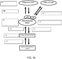
- FIG. 1a shows a general layout 1 of a charge station according to the present invention.
- the system comprises an energy exchange station 2, a data processing device 3, and a configuration device 12.
- the energy exchange station comprises a port for exchanging energy 7 with an energy source, a port for exchanging energy 4 with a vehicle, a port for data communication 6 with the vehicle, and a port for data communication 5 with a data processing device 3.
- the data processing device 3 comprises a port for data communication 5 with the energy exchange station 2, a port for data communication 8 with at least one configuration devices 12 and 15 through an API 13, and a database 10, for storing 9 at least configuration details and battery profiles.
- the configuration devices 12 and 15 comprise a port for exchanging data 11, 14 with the data processing device 3 through the API 13 and means, such as a user interface, for editing the configuration details in the database 10.
- Figure 1b shows a case wherein available grid power is less than the required power demanded by vehicles.
- the grid power is distributed over the charging outputs according to priority of the vehicles to drive away.
- This priority can be entered in the system by a user application which connects to an API in the data processing device.
- This application can be an advanced fleet management software system or a simple user interface where the user can enter how much time he has before he has to drive off again.
- the available grid power can be known to a pre-programmed setting in Data processing device, or through a API which interacts (real time or semi-real time) with the software of a grid provider (smart-grid).
- the numbers in the figure refer to the following steps:
- Figure 1c shows a case wherein the system optimises the charging profile based on a battery life requirement.
- the general rule is that the faster the charging is, the higher the potential impact on battery life.
- the system can know what the battery life requirement for a certain customer is. Based on this requirement the charge profile and speed can be adjusted once a customer connects the vehicle to the system.
- the system can also make a trade-off between the battery life requirement and the available time to get the battery fully charged.
- Figure 1d shows a case wherein the data processing device can interact through an API between billing and payment applications which run at the computers of utilities or other energy providers.
- the system can limit the amount of charging power at a specific charging socket based on the type of subscription a user has for energy delivery. For example a premium subscription can mean that the car can receive 50 kW charging power end be charged very fast, but a basic subscription can mean that the user can only receive 20 kW and charge much slower.
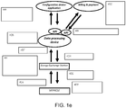
- Figure 1e shows a case similar to the case from figure Id, but here the vehicle does not have a battery management system.
- the system data processing device
- the system can interact through an API between billing and payment applications which run at the computers of utilities or other energy providers.
- the system can limit the amount of charging power at a specific charging socket based on the type of subscription a user has for energy delivery. For example a premium subscription can mean that the car can receive 50 kW charging power end be charged very fast, but a basic subscription can mean that the user can only receive 20 kW and charge much slower.
- Figure If shows a system with an interface for local (international) installation partners which provides information about the functioning of the system. If something goes wrong it can send an error code to the local installation partner (via a data processing device API) so the local installer knows which equipment to bring to do a repair.
- Figure 1g shows an example wherein battery life can be predicted based on historic data of the batteries and this information is offered to leasing companies.
- FIG. 2a shows a schematic view of an example of a electric power converter 700 for use in an energy transfer station according to the invention.
- the energy transfer station comprises a multiphase (for example three phase) AC/DC converter 701, which is coupled to a DC/DC converter 702, comprising a galvanic separation.
- the DC/DC converter is coupled to a multi-phase (for example four) DC/AC converter 703.
- FIG 2b shows a simplified electric scheme of the converter 700 from figure 2a , wherein like numbers indicate like parts.
- the converter uses switches 704, which are controlled by a micro-controller (not shown).
- FIG. 2c shows an example wherein the energy exchange station 705 consists internally of several power converters 706 (for example, but not necessarily AC/DC converters), a connection matrix 707, for changeably coupling the energy converters with ports for exchanging energy with vehicles.
- the ports consist of a connection manager 708, a system which manages the control of one specific connection, an output consisting of data and DC energy port, a charging cable and at the end of the charging cable a connector for coupling the energy exchange station to the vehicle.
- each power converter, or multiple power converters together can be coupled to one output of the energy exchange station.
- this configuration can distribute the power over the multiple outputs of one energy exchange station at different power levels, voltage levels or current levels per output.
- connection managers will manage one connection each (data transfer, power transfer, safety), therefore this configuration enables the use of different connection standards, cables and physical connections on one energy exchange station simultaneously. Additionally, with no additional effort, one connection manager (plus its cable and connector) and thus one energy exchange port can be replaced by another one, as all specific protocols and safety are handled by the connection manager. This increases the flexibility of a energy exchange station to respond to market changes, market penetration of a specific charge system etc.
- Figure 2d shows an embodiment of an energy exchange station 709 which consists internally of a configurable power supply 710 unit with multiple outputs which are coupled (possibly fixed) to the energy exchange ports of the energy exchange station.
- the ports again can consist of a connection manager, a system which manages the control of one specific connection, an output consisting of data and DC energy port, a charging cable and at the end of the charging cable a connector for coupling the energy exchange station to the vehicle.
- the configurable power supply can adjust the current, voltage and power levels per output. As such this configuration can also distribute the power over the multiple outputs of one energy exchange station at different power levels, voltage levels or current levels per output.
- the connection managers can be identical to those described in the previous embodiment.
- FIG. 2e shows an energy exchange station 711 which is a combination of embodiment 1 & 2.
- the energy exchange station can consist internally of a configurable power supply unit with multiple outputs which is connection matrix.
- Figure 2f shows an energy exchange station 712 that in the same way as the connection managers at the output, these kind of connection managers can be installed at the power inputs of the charge station, where they manage data transfer, power transfer and safety of each power input separately.
- connection managers can be implemented to connect and optionally communicate with different sources, such as Grid power (by different grid owners), wind power, solar power, local storage (emergency power or load balancing) or any other source of energy thinkable.
- sources such as Grid power (by different grid owners), wind power, solar power, local storage (emergency power or load balancing) or any other source of energy thinkable.
- the optional communication is of course only possible when the source also has means to communicate.
- connection managers are intelligent and can thus negotiate the need of the charge station with the power source (grid owner) or tell the energy exchange station about energy surplus (which can be used to accelerate charging) when one of the inputs is a windmill and there is more wind than predicted.
Landscapes
- Engineering & Computer Science (AREA)
- Power Engineering (AREA)
- Transportation (AREA)
- Mechanical Engineering (AREA)
- Electric Propulsion And Braking For Vehicles (AREA)
- Charge And Discharge Circuits For Batteries Or The Like (AREA)
- Secondary Cells (AREA)
Applications Claiming Priority (3)
| Application Number | Priority Date | Filing Date | Title |
|---|---|---|---|
| NL2004279A NL2004279C2 (en) | 2010-02-22 | 2010-02-22 | System, device and method for exchanging energy with an electric vehicle. |
| PCT/NL2011/050122 WO2011102727A2 (en) | 2010-02-22 | 2011-02-22 | System, device and method for exchanging energy with an electric vehicle |
| EP11706641.5A EP2539175B1 (en) | 2010-02-22 | 2011-02-22 | System, device and method for exchanging energy with an electric vehicle |
Related Parent Applications (3)
| Application Number | Title | Priority Date | Filing Date |
|---|---|---|---|
| EP11706641.5A Division-Into EP2539175B1 (en) | 2010-02-22 | 2011-02-22 | System, device and method for exchanging energy with an electric vehicle |
| EP11706641.5A Division EP2539175B1 (en) | 2010-02-22 | 2011-02-22 | System, device and method for exchanging energy with an electric vehicle |
| EP11706641.5 Division | 2011-02-22 |
Publications (2)
| Publication Number | Publication Date |
|---|---|
| EP2546094A1 EP2546094A1 (en) | 2013-01-16 |
| EP2546094B1 true EP2546094B1 (en) | 2020-04-08 |
Family
ID=42790737
Family Applications (3)
| Application Number | Title | Priority Date | Filing Date |
|---|---|---|---|
| EP12187206.3A Active EP2546094B1 (en) | 2010-02-22 | 2011-02-22 | System, device and method for exchanging energy with an electric vehicle |
| EP11706641.5A Active EP2539175B1 (en) | 2010-02-22 | 2011-02-22 | System, device and method for exchanging energy with an electric vehicle |
| EP18193856.4A Withdrawn EP3492307A1 (en) | 2010-02-22 | 2011-02-22 | System, device and method for exchanging energy with an electric vehicle |
Family Applications After (2)
| Application Number | Title | Priority Date | Filing Date |
|---|---|---|---|
| EP11706641.5A Active EP2539175B1 (en) | 2010-02-22 | 2011-02-22 | System, device and method for exchanging energy with an electric vehicle |
| EP18193856.4A Withdrawn EP3492307A1 (en) | 2010-02-22 | 2011-02-22 | System, device and method for exchanging energy with an electric vehicle |
Country Status (15)
| Country | Link |
|---|---|
| US (1) | US20130103191A1 (ru) |
| EP (3) | EP2546094B1 (ru) |
| JP (1) | JP5738901B2 (ru) |
| CN (1) | CN102892617B (ru) |
| BR (1) | BR112012021130B8 (ru) |
| CA (1) | CA2790950C (ru) |
| DK (1) | DK2539175T3 (ru) |
| ES (1) | ES2703584T3 (ru) |
| NL (1) | NL2004279C2 (ru) |
| PL (1) | PL2539175T3 (ru) |
| PT (1) | PT2539175T (ru) |
| RU (1) | RU2550109C2 (ru) |
| TR (1) | TR201818873T4 (ru) |
| TW (1) | TWI531132B (ru) |
| WO (1) | WO2011102727A2 (ru) |
Families Citing this family (33)
| Publication number | Priority date | Publication date | Assignee | Title |
|---|---|---|---|---|
| US10782721B2 (en) * | 2012-08-27 | 2020-09-22 | Stem, Inc. | Method and apparatus for balancing power on a per phase basis in multi-phase electrical load facilities using an energy storage system |
| EP2756981A1 (en) | 2013-01-16 | 2014-07-23 | Abb B.V. | System for exchanging energy with an electric vehicle |
| WO2014177608A2 (en) * | 2013-04-30 | 2014-11-06 | Nec Europe Ltd. | Method for allocating electrical power of a shared energy source and resource management system |
| US9401610B2 (en) | 2013-09-19 | 2016-07-26 | Honda Motor Co., Ltd. | System and method for electric vehicle battery charging |
| ES2837356T3 (es) * | 2013-11-06 | 2021-06-30 | Abb Schweiz Ag | Cargador para vehículos eléctricos con arbitraje de convertidor de energía distribuida |
| CN103595107B (zh) * | 2013-12-02 | 2015-11-11 | 国家电网公司 | 电动汽车充放电控制系统及方法 |
| US9463705B2 (en) * | 2014-06-10 | 2016-10-11 | Qualcomm Incorporated | System and method for adaptive charging compliance control |
| DE102014212415A1 (de) * | 2014-06-27 | 2015-12-31 | Robert Bosch Gmbh | Verfahren zum Betreiben einer Ladestation |
| US9315108B2 (en) * | 2014-07-08 | 2016-04-19 | Toyota Jidosha Kabushiki Kaisha | Vehicle function determination |
| JP5918330B2 (ja) * | 2014-10-01 | 2016-05-18 | 株式会社東光高岳 | 電気移動体用充電装置 |
| CN105346405B (zh) * | 2015-10-27 | 2018-03-13 | 北京新能源汽车股份有限公司 | 电动汽车及其电池包监测系统 |
| RU2623621C1 (ru) * | 2015-12-02 | 2017-06-28 | Публичное акционерное общество "Межрегиональная распределительная сетевая компания Центра и Приволжья" | Система для обмена энергией с электротранспортным средством |
| US10759281B2 (en) * | 2016-01-19 | 2020-09-01 | Ford Global Technologies, Llc | Controlling operation of electrified vehicle travelling on inductive roadway to influence electrical grid |
| RU174433U1 (ru) * | 2016-07-07 | 2017-10-12 | Сергей Александрович Иванов | Устройство зарядки батареи с гальванической развязкой |
| WO2018038423A1 (ko) * | 2016-08-23 | 2018-03-01 | 삼성전자 주식회사 | 전력 제공 장치 및 전력을 수신하는 전자 장치와 그 제어 방법 |
| CN106356964A (zh) * | 2016-09-12 | 2017-01-25 | 国网上海市电力公司 | 具有信息反馈的功能的供电装置 |
| DE102017116887A1 (de) | 2017-07-26 | 2019-01-31 | Wobben Properties Gmbh | Ladestation mit dynamischer Ladestromverteilung |
| DE102017116886A1 (de) | 2017-07-26 | 2019-01-31 | Wobben Properties Gmbh | Ladestation mit dynamischer Ladestromverteilung |
| CN110194076B (zh) * | 2018-02-26 | 2024-04-09 | 周锡卫 | 一种适于人工换电的多直流储能模块系统的控制方法 |
| DE102018203192A1 (de) | 2018-03-02 | 2019-09-05 | Schmidhauser Ag | Lade-System |
| DE102018113174A1 (de) | 2018-06-04 | 2019-12-05 | Dr. Ing. H.C. F. Porsche Aktiengesellschaft | Universelles Ladegerät für Gleich- und Wechselstromladen |
| NO20190023A1 (en) * | 2019-01-07 | 2020-07-08 | Easee As | Electrical assembly for a charging station |
| US11135936B2 (en) | 2019-03-06 | 2021-10-05 | Fermata, LLC | Methods for using temperature data to protect electric vehicle battery health during use of bidirectional charger |
| CN110053507B (zh) * | 2019-05-07 | 2021-05-11 | 广东电网有限责任公司 | 一种电动汽车充电控制方法及装置 |
| CN112829627A (zh) | 2019-11-22 | 2021-05-25 | 台达电子企业管理(上海)有限公司 | 用于对多辆电动汽车进行充电的功率分配系统及方法 |
| US11958372B2 (en) | 2019-11-26 | 2024-04-16 | Fermata Energy Llc | Device for bi-directional power conversion and charging for use with electric vehicles |
| US11642977B2 (en) * | 2020-07-09 | 2023-05-09 | Weave Grid, Inc. | Optimized charging of electric vehicles over distribution grid |
| US20220200295A1 (en) * | 2020-12-23 | 2022-06-23 | Medtronic, Inc. | Systems and method for charging batteries |
| US11554684B2 (en) * | 2021-02-17 | 2023-01-17 | AMPLY Power, Inc. | Aggregating capacity for depot charging |
| US20230147536A1 (en) * | 2021-11-10 | 2023-05-11 | Powermat Technologies Ltd. | Green battery charger and framework |
| CN114368312A (zh) * | 2022-01-11 | 2022-04-19 | 青岛特来电新能源科技有限公司 | 车辆信息的处理方法、装置、电子设备及介质 |
| US20240042874A1 (en) * | 2022-07-07 | 2024-02-08 | Ivys Inc. | Hybrid electric and hydrogen dispensing systems and methods |
| US11760224B1 (en) * | 2022-08-03 | 2023-09-19 | Electric Era Technologies, Inc. | Vehicle charging system |
Family Cites Families (28)
| Publication number | Priority date | Publication date | Assignee | Title |
|---|---|---|---|---|
| US5225762A (en) * | 1990-04-30 | 1993-07-06 | George Langford | Battery management system |
| CA2038160C (en) * | 1991-03-13 | 1996-10-22 | Jiri K. Nor | Charging circuits for rechargeable batteries and cells |
| JPH04358950A (ja) * | 1991-05-31 | 1992-12-11 | Honda Motor Co Ltd | 電動式車両 |
| US5461298A (en) * | 1993-01-15 | 1995-10-24 | Hughes Aircraft Company | Automatic electric vehicle charging system |
| US5401174A (en) * | 1994-03-30 | 1995-03-28 | Chrysler Corporation | Universal charge port connector for electric vehicles |
| US5548200A (en) * | 1994-07-06 | 1996-08-20 | Norvik Traction Inc. | Universal charging station and method for charging electric vehicle batteries |
| US5498948A (en) * | 1994-10-14 | 1996-03-12 | Delco Electornics | Self-aligning inductive charger |
| US5803215A (en) * | 1997-01-22 | 1998-09-08 | Schott Power Systems Incorporated | Method and apparatus for charging a plurality of electric vehicles |
| US6371768B1 (en) * | 1998-03-31 | 2002-04-16 | Daimlerchrysler Corporation | Universal charge port connector for electric vehicles |
| US7256516B2 (en) * | 2000-06-14 | 2007-08-14 | Aerovironment Inc. | Battery charging system and method |
| US20020070705A1 (en) * | 2000-06-14 | 2002-06-13 | Buchanan William D. | Battery charging system and method |
| DE20013399U1 (de) * | 2000-08-03 | 2000-11-02 | Chai Wellmon | Ladestation für elektrisch betriebene Fahrzeuge |
| EP1263111B1 (en) * | 2001-05-29 | 2010-11-24 | Canon Kabushiki Kaisha | Method, program and apparatus for detecting internal information of a rechargeable battery and apparatus including said detecting apparatus |
| DE10233821A1 (de) * | 2002-07-25 | 2004-02-05 | Daimlerchrysler Ag | Verfahren und Anordnung zur Steuerung der Energieversorgung einer wenigstens einen elektrischen Antriebsmotor aufweisenden, mobilen Vorrichtung mit einem hybriden Energiesystem, das ein Brennstoffzellensystem und ein dynamisches Energiesystem enthält |
| MXPA05004094A (es) * | 2002-10-15 | 2005-07-13 | Vector Prod Inc | Cargador de bateria de alta frecuencia y metodo para su operacion. |
| JP2006074868A (ja) * | 2004-08-31 | 2006-03-16 | Fuji Heavy Ind Ltd | 電気自動車のバッテリ充電システム |
| JP2006113892A (ja) * | 2004-10-15 | 2006-04-27 | Fuji Heavy Ind Ltd | 電気自動車自動運行マネジメントシステム |
| JP4678243B2 (ja) * | 2005-06-08 | 2011-04-27 | トヨタ自動車株式会社 | 電力供給システム |
| JP2007143370A (ja) * | 2005-11-22 | 2007-06-07 | Toyota Motor Corp | 充電装置、電動車両および充電システム |
| US20080040295A1 (en) * | 2006-08-10 | 2008-02-14 | V2 Green, Inc. | Power Aggregation System for Distributed Electric Resources |
| JP5228322B2 (ja) * | 2006-08-30 | 2013-07-03 | トヨタ自動車株式会社 | 蓄電装置の劣化評価システム、車両、蓄電装置の劣化評価方法およびその劣化評価方法をコンピュータに実行させるためのプログラムを記録したコンピュータ読取可能な記録媒体 |
| JP4441691B2 (ja) * | 2007-02-06 | 2010-03-31 | 国立大学法人東京工業大学 | 交流/直流電力変換装置 |
| DE102007032415B3 (de) * | 2007-07-12 | 2009-04-02 | Sauer-Danfoss Aps | Hydraulische Ventilanordnung |
| US7928735B2 (en) * | 2007-07-23 | 2011-04-19 | Yung-Sheng Huang | Battery performance monitor |
| WO2009013891A1 (ja) * | 2007-07-25 | 2009-01-29 | Panasonic Corporation | 車両用電源装置 |
| US8912753B2 (en) * | 2007-10-04 | 2014-12-16 | General Motors Llc. | Remote power usage management for plug-in vehicles |
| CN201118266Y (zh) * | 2007-11-01 | 2008-09-17 | 天津市詹佛斯科技发展有限公司 | 牵引式蓄电池用充电机充电控制器 |
| JP5336810B2 (ja) * | 2007-12-28 | 2013-11-06 | 大阪瓦斯株式会社 | 車両及びエネルギ供給システム |
-
2010
- 2010-02-22 NL NL2004279A patent/NL2004279C2/en not_active IP Right Cessation
-
2011
- 2011-02-22 TW TW100105742A patent/TWI531132B/zh active
- 2011-02-22 DK DK11706641.5T patent/DK2539175T3/en active
- 2011-02-22 EP EP12187206.3A patent/EP2546094B1/en active Active
- 2011-02-22 CA CA2790950A patent/CA2790950C/en active Active
- 2011-02-22 CN CN201180020165.XA patent/CN102892617B/zh active Active
- 2011-02-22 EP EP11706641.5A patent/EP2539175B1/en active Active
- 2011-02-22 RU RU2012140427/11A patent/RU2550109C2/ru active
- 2011-02-22 JP JP2012554953A patent/JP5738901B2/ja active Active
- 2011-02-22 TR TR2018/18873T patent/TR201818873T4/tr unknown
- 2011-02-22 PT PT11706641T patent/PT2539175T/pt unknown
- 2011-02-22 BR BR112012021130A patent/BR112012021130B8/pt active IP Right Grant
- 2011-02-22 US US13/580,634 patent/US20130103191A1/en not_active Abandoned
- 2011-02-22 PL PL11706641T patent/PL2539175T3/pl unknown
- 2011-02-22 ES ES11706641T patent/ES2703584T3/es active Active
- 2011-02-22 WO PCT/NL2011/050122 patent/WO2011102727A2/en active Application Filing
- 2011-02-22 EP EP18193856.4A patent/EP3492307A1/en not_active Withdrawn
Non-Patent Citations (1)
| Title |
|---|
| None * |
Also Published As
| Publication number | Publication date |
|---|---|
| EP2539175B1 (en) | 2018-09-12 |
| EP2539175A2 (en) | 2013-01-02 |
| CA2790950A1 (en) | 2011-08-25 |
| JP2013520955A (ja) | 2013-06-06 |
| BR112012021130A2 (pt) | 2021-04-20 |
| WO2011102727A3 (en) | 2012-06-21 |
| CA2790950C (en) | 2021-10-19 |
| PL2539175T3 (pl) | 2019-03-29 |
| EP3492307A1 (en) | 2019-06-05 |
| ES2703584T3 (es) | 2019-03-11 |
| WO2011102727A2 (en) | 2011-08-25 |
| TWI531132B (zh) | 2016-04-21 |
| NL2004279C2 (en) | 2011-08-23 |
| TR201818873T4 (tr) | 2019-01-21 |
| EP2546094A1 (en) | 2013-01-16 |
| CN102892617A (zh) | 2013-01-23 |
| PT2539175T (pt) | 2018-12-19 |
| US20130103191A1 (en) | 2013-04-25 |
| TW201203777A (en) | 2012-01-16 |
| RU2012140427A (ru) | 2014-03-27 |
| JP5738901B2 (ja) | 2015-06-24 |
| RU2550109C2 (ru) | 2015-05-10 |
| BR112012021130B1 (pt) | 2021-08-17 |
| DK2539175T3 (en) | 2019-01-14 |
| CN102892617B (zh) | 2016-10-26 |
| BR112012021130B8 (pt) | 2023-03-28 |
Similar Documents
| Publication | Publication Date | Title |
|---|---|---|
| EP2546094B1 (en) | System, device and method for exchanging energy with an electric vehicle | |
| US10906423B2 (en) | Power aggregation system for distributed electric resources | |
| Anwar et al. | Assessing the value of electric vehicle managed charging: a review of methodologies and results | |
| US20190061535A1 (en) | Electric vehicle power management systems | |
| TWI499159B (zh) | 控制充電站之方法、與相關充電站、低電壓變電站及系統 | |
| US8085034B2 (en) | Managing charging of electric vehicles | |
| US20130307466A1 (en) | System and Method for Charging Car Batteries | |
| US20110196692A1 (en) | Apparatus, system and method for grid storage | |
| EP3812197A1 (en) | System and procedure for automatic, controlled and flexible charging of electric vehicles | |
| KR20210121064A (ko) | 전력 관리형 전기 자동차 충전 스테이션 | |
| Strindberg | Analysis of Battery Integrated Fast-Charging Station for Electric Vehicles | |
| CN116638983A (zh) | 电动化车辆车队充电控制系统和方法 |
Legal Events
| Date | Code | Title | Description |
|---|---|---|---|
| PUAI | Public reference made under article 153(3) epc to a published international application that has entered the european phase |
Free format text: ORIGINAL CODE: 0009012 |
|
| AC | Divisional application: reference to earlier application |
Ref document number: 2539175 Country of ref document: EP Kind code of ref document: P |
|
| AK | Designated contracting states |
Kind code of ref document: A1 Designated state(s): AL AT BE BG CH CY CZ DE DK EE ES FI FR GB GR HR HU IE IS IT LI LT LU LV MC MK MT NL NO PL PT RO RS SE SI SK SM TR |
|
| AX | Request for extension of the european patent |
Extension state: BA ME |
|
| 17P | Request for examination filed |
Effective date: 20130716 |
|
| RBV | Designated contracting states (corrected) |
Designated state(s): AL AT BE BG CH CY CZ DE DK EE ES FI FR GB GR HR HU IE IS IT LI LT LU LV MC MK MT NL NO PL PT RO RS SE SI SK SM TR |
|
| STAA | Information on the status of an ep patent application or granted ep patent |
Free format text: STATUS: EXAMINATION IS IN PROGRESS |
|
| 17Q | First examination report despatched |
Effective date: 20171102 |
|
| REG | Reference to a national code |
Ref country code: DE Ref legal event code: R079 Ref document number: 602011066209 Country of ref document: DE Free format text: PREVIOUS MAIN CLASS: B60L0011180000 Ipc: B60L0053660000 |
|
| GRAP | Despatch of communication of intention to grant a patent |
Free format text: ORIGINAL CODE: EPIDOSNIGR1 |
|
| STAA | Information on the status of an ep patent application or granted ep patent |
Free format text: STATUS: GRANT OF PATENT IS INTENDED |
|
| RIC1 | Information provided on ipc code assigned before grant |
Ipc: B60L 53/66 20190101AFI20190913BHEP |
|
| INTG | Intention to grant announced |
Effective date: 20191023 |
|
| GRAS | Grant fee paid |
Free format text: ORIGINAL CODE: EPIDOSNIGR3 |
|
| GRAA | (expected) grant |
Free format text: ORIGINAL CODE: 0009210 |
|
| STAA | Information on the status of an ep patent application or granted ep patent |
Free format text: STATUS: THE PATENT HAS BEEN GRANTED |
|
| AC | Divisional application: reference to earlier application |
Ref document number: 2539175 Country of ref document: EP Kind code of ref document: P |
|
| AK | Designated contracting states |
Kind code of ref document: B1 Designated state(s): AL AT BE BG CH CY CZ DE DK EE ES FI FR GB GR HR HU IE IS IT LI LT LU LV MC MK MT NL NO PL PT RO RS SE SI SK SM TR |
|
| REG | Reference to a national code |
Ref country code: GB Ref legal event code: FG4D |
|
| REG | Reference to a national code |
Ref country code: AT Ref legal event code: REF Ref document number: 1253927 Country of ref document: AT Kind code of ref document: T Effective date: 20200415 Ref country code: CH Ref legal event code: EP |
|
| REG | Reference to a national code |
Ref country code: DE Ref legal event code: R096 Ref document number: 602011066209 Country of ref document: DE |
|
| REG | Reference to a national code |
Ref country code: IE Ref legal event code: FG4D |
|
| REG | Reference to a national code |
Ref country code: NL Ref legal event code: MP Effective date: 20200408 |
|
| REG | Reference to a national code |
Ref country code: LT Ref legal event code: MG4D |
|
| PG25 | Lapsed in a contracting state [announced via postgrant information from national office to epo] |
Ref country code: NL Free format text: LAPSE BECAUSE OF FAILURE TO SUBMIT A TRANSLATION OF THE DESCRIPTION OR TO PAY THE FEE WITHIN THE PRESCRIBED TIME-LIMIT Effective date: 20200408 Ref country code: SE Free format text: LAPSE BECAUSE OF FAILURE TO SUBMIT A TRANSLATION OF THE DESCRIPTION OR TO PAY THE FEE WITHIN THE PRESCRIBED TIME-LIMIT Effective date: 20200408 Ref country code: IS Free format text: LAPSE BECAUSE OF FAILURE TO SUBMIT A TRANSLATION OF THE DESCRIPTION OR TO PAY THE FEE WITHIN THE PRESCRIBED TIME-LIMIT Effective date: 20200808 Ref country code: LT Free format text: LAPSE BECAUSE OF FAILURE TO SUBMIT A TRANSLATION OF THE DESCRIPTION OR TO PAY THE FEE WITHIN THE PRESCRIBED TIME-LIMIT Effective date: 20200408 Ref country code: PT Free format text: LAPSE BECAUSE OF FAILURE TO SUBMIT A TRANSLATION OF THE DESCRIPTION OR TO PAY THE FEE WITHIN THE PRESCRIBED TIME-LIMIT Effective date: 20200817 Ref country code: FI Free format text: LAPSE BECAUSE OF FAILURE TO SUBMIT A TRANSLATION OF THE DESCRIPTION OR TO PAY THE FEE WITHIN THE PRESCRIBED TIME-LIMIT Effective date: 20200408 Ref country code: GR Free format text: LAPSE BECAUSE OF FAILURE TO SUBMIT A TRANSLATION OF THE DESCRIPTION OR TO PAY THE FEE WITHIN THE PRESCRIBED TIME-LIMIT Effective date: 20200709 Ref country code: NO Free format text: LAPSE BECAUSE OF FAILURE TO SUBMIT A TRANSLATION OF THE DESCRIPTION OR TO PAY THE FEE WITHIN THE PRESCRIBED TIME-LIMIT Effective date: 20200708 |
|
| REG | Reference to a national code |
Ref country code: AT Ref legal event code: MK05 Ref document number: 1253927 Country of ref document: AT Kind code of ref document: T Effective date: 20200408 |
|
| PG25 | Lapsed in a contracting state [announced via postgrant information from national office to epo] |
Ref country code: HR Free format text: LAPSE BECAUSE OF FAILURE TO SUBMIT A TRANSLATION OF THE DESCRIPTION OR TO PAY THE FEE WITHIN THE PRESCRIBED TIME-LIMIT Effective date: 20200408 Ref country code: LV Free format text: LAPSE BECAUSE OF FAILURE TO SUBMIT A TRANSLATION OF THE DESCRIPTION OR TO PAY THE FEE WITHIN THE PRESCRIBED TIME-LIMIT Effective date: 20200408 Ref country code: BG Free format text: LAPSE BECAUSE OF FAILURE TO SUBMIT A TRANSLATION OF THE DESCRIPTION OR TO PAY THE FEE WITHIN THE PRESCRIBED TIME-LIMIT Effective date: 20200708 Ref country code: RS Free format text: LAPSE BECAUSE OF FAILURE TO SUBMIT A TRANSLATION OF THE DESCRIPTION OR TO PAY THE FEE WITHIN THE PRESCRIBED TIME-LIMIT Effective date: 20200408 |
|
| PG25 | Lapsed in a contracting state [announced via postgrant information from national office to epo] |
Ref country code: AL Free format text: LAPSE BECAUSE OF FAILURE TO SUBMIT A TRANSLATION OF THE DESCRIPTION OR TO PAY THE FEE WITHIN THE PRESCRIBED TIME-LIMIT Effective date: 20200408 |
|
| REG | Reference to a national code |
Ref country code: DE Ref legal event code: R097 Ref document number: 602011066209 Country of ref document: DE |
|
| PG25 | Lapsed in a contracting state [announced via postgrant information from national office to epo] |
Ref country code: RO Free format text: LAPSE BECAUSE OF FAILURE TO SUBMIT A TRANSLATION OF THE DESCRIPTION OR TO PAY THE FEE WITHIN THE PRESCRIBED TIME-LIMIT Effective date: 20200408 Ref country code: AT Free format text: LAPSE BECAUSE OF FAILURE TO SUBMIT A TRANSLATION OF THE DESCRIPTION OR TO PAY THE FEE WITHIN THE PRESCRIBED TIME-LIMIT Effective date: 20200408 Ref country code: CZ Free format text: LAPSE BECAUSE OF FAILURE TO SUBMIT A TRANSLATION OF THE DESCRIPTION OR TO PAY THE FEE WITHIN THE PRESCRIBED TIME-LIMIT Effective date: 20200408 Ref country code: IT Free format text: LAPSE BECAUSE OF FAILURE TO SUBMIT A TRANSLATION OF THE DESCRIPTION OR TO PAY THE FEE WITHIN THE PRESCRIBED TIME-LIMIT Effective date: 20200408 Ref country code: SM Free format text: LAPSE BECAUSE OF FAILURE TO SUBMIT A TRANSLATION OF THE DESCRIPTION OR TO PAY THE FEE WITHIN THE PRESCRIBED TIME-LIMIT Effective date: 20200408 Ref country code: EE Free format text: LAPSE BECAUSE OF FAILURE TO SUBMIT A TRANSLATION OF THE DESCRIPTION OR TO PAY THE FEE WITHIN THE PRESCRIBED TIME-LIMIT Effective date: 20200408 Ref country code: DK Free format text: LAPSE BECAUSE OF FAILURE TO SUBMIT A TRANSLATION OF THE DESCRIPTION OR TO PAY THE FEE WITHIN THE PRESCRIBED TIME-LIMIT Effective date: 20200408 Ref country code: ES Free format text: LAPSE BECAUSE OF FAILURE TO SUBMIT A TRANSLATION OF THE DESCRIPTION OR TO PAY THE FEE WITHIN THE PRESCRIBED TIME-LIMIT Effective date: 20200408 |
|
| PLBE | No opposition filed within time limit |
Free format text: ORIGINAL CODE: 0009261 |
|
| STAA | Information on the status of an ep patent application or granted ep patent |
Free format text: STATUS: NO OPPOSITION FILED WITHIN TIME LIMIT |
|
| PG25 | Lapsed in a contracting state [announced via postgrant information from national office to epo] |
Ref country code: SK Free format text: LAPSE BECAUSE OF FAILURE TO SUBMIT A TRANSLATION OF THE DESCRIPTION OR TO PAY THE FEE WITHIN THE PRESCRIBED TIME-LIMIT Effective date: 20200408 Ref country code: PL Free format text: LAPSE BECAUSE OF FAILURE TO SUBMIT A TRANSLATION OF THE DESCRIPTION OR TO PAY THE FEE WITHIN THE PRESCRIBED TIME-LIMIT Effective date: 20200408 |
|
| 26N | No opposition filed |
Effective date: 20210112 |
|
| PG25 | Lapsed in a contracting state [announced via postgrant information from national office to epo] |
Ref country code: SI Free format text: LAPSE BECAUSE OF FAILURE TO SUBMIT A TRANSLATION OF THE DESCRIPTION OR TO PAY THE FEE WITHIN THE PRESCRIBED TIME-LIMIT Effective date: 20200408 |
|
| PG25 | Lapsed in a contracting state [announced via postgrant information from national office to epo] |
Ref country code: MC Free format text: LAPSE BECAUSE OF FAILURE TO SUBMIT A TRANSLATION OF THE DESCRIPTION OR TO PAY THE FEE WITHIN THE PRESCRIBED TIME-LIMIT Effective date: 20200408 |
|
| REG | Reference to a national code |
Ref country code: BE Ref legal event code: MM Effective date: 20210228 |
|
| PG25 | Lapsed in a contracting state [announced via postgrant information from national office to epo] |
Ref country code: CH Free format text: LAPSE BECAUSE OF NON-PAYMENT OF DUE FEES Effective date: 20210228 Ref country code: LI Free format text: LAPSE BECAUSE OF NON-PAYMENT OF DUE FEES Effective date: 20210228 Ref country code: LU Free format text: LAPSE BECAUSE OF NON-PAYMENT OF DUE FEES Effective date: 20210222 |
|
| REG | Reference to a national code |
Ref country code: DE Ref legal event code: R081 Ref document number: 602011066209 Country of ref document: DE Owner name: ABB E-MOBILITY B.V., NL Free format text: FORMER OWNER: ABB B.V., ROTTERDAM, NL Ref country code: DE Ref legal event code: R081 Ref document number: 602011066209 Country of ref document: DE Owner name: ABB SCHWEIZ AG, CH Free format text: FORMER OWNER: ABB B.V., ROTTERDAM, NL Ref country code: DE Ref legal event code: R082 Ref document number: 602011066209 Country of ref document: DE Representative=s name: DENNEMEYER & ASSOCIATES S.A., DE Ref country code: DE Ref legal event code: R082 Ref document number: 602011066209 Country of ref document: DE Representative=s name: MAIWALD GMBH, DE |
|
| REG | Reference to a national code |
Ref country code: GB Ref legal event code: 732E Free format text: REGISTERED BETWEEN 20211118 AND 20211124 |
|
| PG25 | Lapsed in a contracting state [announced via postgrant information from national office to epo] |
Ref country code: IE Free format text: LAPSE BECAUSE OF NON-PAYMENT OF DUE FEES Effective date: 20210222 |
|
| PG25 | Lapsed in a contracting state [announced via postgrant information from national office to epo] |
Ref country code: BE Free format text: LAPSE BECAUSE OF NON-PAYMENT OF DUE FEES Effective date: 20210228 |
|
| PGFP | Annual fee paid to national office [announced via postgrant information from national office to epo] |
Ref country code: FR Payment date: 20230221 Year of fee payment: 13 |
|
| PG25 | Lapsed in a contracting state [announced via postgrant information from national office to epo] |
Ref country code: HU Free format text: LAPSE BECAUSE OF FAILURE TO SUBMIT A TRANSLATION OF THE DESCRIPTION OR TO PAY THE FEE WITHIN THE PRESCRIBED TIME-LIMIT; INVALID AB INITIO Effective date: 20110222 Ref country code: CY Free format text: LAPSE BECAUSE OF FAILURE TO SUBMIT A TRANSLATION OF THE DESCRIPTION OR TO PAY THE FEE WITHIN THE PRESCRIBED TIME-LIMIT Effective date: 20200408 |
|
| REG | Reference to a national code |
Ref country code: DE Ref legal event code: R081 Ref document number: 602011066209 Country of ref document: DE Owner name: ABB E-MOBILITY B.V., NL Free format text: FORMER OWNER: ABB SCHWEIZ AG, BADEN, CH |
|
| REG | Reference to a national code |
Ref country code: GB Ref legal event code: 732E Free format text: REGISTERED BETWEEN 20230706 AND 20230712 |
|
| REG | Reference to a national code |
Ref country code: DE Ref legal event code: R082 Ref document number: 602011066209 Country of ref document: DE Representative=s name: MAIWALD GMBH, DE |
|
| PG25 | Lapsed in a contracting state [announced via postgrant information from national office to epo] |
Ref country code: MK Free format text: LAPSE BECAUSE OF FAILURE TO SUBMIT A TRANSLATION OF THE DESCRIPTION OR TO PAY THE FEE WITHIN THE PRESCRIBED TIME-LIMIT Effective date: 20200408 |
|
| PGFP | Annual fee paid to national office [announced via postgrant information from national office to epo] |
Ref country code: DE Payment date: 20240219 Year of fee payment: 14 Ref country code: GB Payment date: 20240219 Year of fee payment: 14 |