EP2545219B1 - Concrete element with an underside plastic sole - Google Patents
Concrete element with an underside plastic sole Download PDFInfo
- Publication number
- EP2545219B1 EP2545219B1 EP20110710720 EP11710720A EP2545219B1 EP 2545219 B1 EP2545219 B1 EP 2545219B1 EP 20110710720 EP20110710720 EP 20110710720 EP 11710720 A EP11710720 A EP 11710720A EP 2545219 B1 EP2545219 B1 EP 2545219B1
- Authority
- EP
- European Patent Office
- Prior art keywords
- concrete
- fibers
- fiber
- concrete body
- embedded
- Prior art date
- Legal status (The legal status is an assumption and is not a legal conclusion. Google has not performed a legal analysis and makes no representation as to the accuracy of the status listed.)
- Active
Links
- 239000004567 concrete Substances 0.000 title claims description 76
- 239000004033 plastic Substances 0.000 title claims description 25
- 229920003023 plastic Polymers 0.000 title claims description 25
- 239000000835 fiber Substances 0.000 claims description 80
- 241001669679 Eleotris Species 0.000 claims description 12
- PXFBZOLANLWPMH-UHFFFAOYSA-N 16-Epiaffinine Natural products C1C(C2=CC=CC=C2N2)=C2C(=O)CC2C(=CC)CN(C)C1C2CO PXFBZOLANLWPMH-UHFFFAOYSA-N 0.000 claims description 2
- 239000010410 layer Substances 0.000 claims 3
- 239000002356 single layer Substances 0.000 claims 1
- 239000011148 porous material Substances 0.000 description 15
- 239000004568 cement Substances 0.000 description 12
- 230000036571 hydration Effects 0.000 description 9
- 238000006703 hydration reaction Methods 0.000 description 9
- OSGAYBCDTDRGGQ-UHFFFAOYSA-L calcium sulfate Chemical compound [Ca+2].[O-]S([O-])(=O)=O OSGAYBCDTDRGGQ-UHFFFAOYSA-L 0.000 description 5
- 238000006243 chemical reaction Methods 0.000 description 5
- XLYOFNOQVPJJNP-UHFFFAOYSA-N water Substances O XLYOFNOQVPJJNP-UHFFFAOYSA-N 0.000 description 5
- 239000004746 geotextile Substances 0.000 description 4
- 238000004519 manufacturing process Methods 0.000 description 4
- 239000004745 nonwoven fabric Substances 0.000 description 4
- -1 For example Substances 0.000 description 3
- 230000015572 biosynthetic process Effects 0.000 description 3
- 235000011132 calcium sulphate Nutrition 0.000 description 3
- 238000000576 coating method Methods 0.000 description 3
- 239000002131 composite material Substances 0.000 description 3
- 239000000470 constituent Substances 0.000 description 3
- HOOWDPSAHIOHCC-UHFFFAOYSA-N dialuminum tricalcium oxygen(2-) Chemical compound [O--].[O--].[O--].[O--].[O--].[O--].[Al+3].[Al+3].[Ca++].[Ca++].[Ca++] HOOWDPSAHIOHCC-UHFFFAOYSA-N 0.000 description 3
- 239000002657 fibrous material Substances 0.000 description 3
- 238000010348 incorporation Methods 0.000 description 3
- 239000000463 material Substances 0.000 description 3
- 238000000034 method Methods 0.000 description 3
- 230000008569 process Effects 0.000 description 3
- 239000011248 coating agent Substances 0.000 description 2
- BCAARMUWIRURQS-UHFFFAOYSA-N dicalcium;oxocalcium;silicate Chemical compound [Ca+2].[Ca+2].[Ca]=O.[O-][Si]([O-])([O-])[O-] BCAARMUWIRURQS-UHFFFAOYSA-N 0.000 description 2
- 230000000694 effects Effects 0.000 description 2
- 239000013013 elastic material Substances 0.000 description 2
- 238000005516 engineering process Methods 0.000 description 2
- 238000009472 formulation Methods 0.000 description 2
- 229910052751 metal Inorganic materials 0.000 description 2
- 239000002184 metal Substances 0.000 description 2
- 239000000203 mixture Substances 0.000 description 2
- 239000002985 plastic film Substances 0.000 description 2
- 239000011513 prestressed concrete Substances 0.000 description 2
- 230000002787 reinforcement Effects 0.000 description 2
- 239000004753 textile Substances 0.000 description 2
- 229910021534 tricalcium silicate Inorganic materials 0.000 description 2
- 235000019976 tricalcium silicate Nutrition 0.000 description 2
- OYPRJOBELJOOCE-UHFFFAOYSA-N Calcium Chemical compound [Ca] OYPRJOBELJOOCE-UHFFFAOYSA-N 0.000 description 1
- 101000601610 Drosophila melanogaster Heparan sulfate N-sulfotransferase Proteins 0.000 description 1
- 238000010521 absorption reaction Methods 0.000 description 1
- 230000009471 action Effects 0.000 description 1
- 239000000853 adhesive Substances 0.000 description 1
- 238000004026 adhesive bonding Methods 0.000 description 1
- 230000001070 adhesive effect Effects 0.000 description 1
- 150000004645 aluminates Chemical class 0.000 description 1
- 238000000889 atomisation Methods 0.000 description 1
- 230000008901 benefit Effects 0.000 description 1
- 229910052791 calcium Inorganic materials 0.000 description 1
- 239000011575 calcium Substances 0.000 description 1
- AXCZMVOFGPJBDE-UHFFFAOYSA-L calcium dihydroxide Chemical compound [OH-].[OH-].[Ca+2] AXCZMVOFGPJBDE-UHFFFAOYSA-L 0.000 description 1
- 239000000920 calcium hydroxide Substances 0.000 description 1
- 229910001861 calcium hydroxide Inorganic materials 0.000 description 1
- 229910052918 calcium silicate Inorganic materials 0.000 description 1
- 239000000378 calcium silicate Substances 0.000 description 1
- 239000011083 cement mortar Substances 0.000 description 1
- 239000003795 chemical substances by application Substances 0.000 description 1
- 230000001427 coherent effect Effects 0.000 description 1
- 230000000295 complement effect Effects 0.000 description 1
- 238000010276 construction Methods 0.000 description 1
- 239000013078 crystal Substances 0.000 description 1
- 230000007547 defect Effects 0.000 description 1
- 230000001934 delay Effects 0.000 description 1
- 238000011161 development Methods 0.000 description 1
- 229910001653 ettringite Inorganic materials 0.000 description 1
- 229910052602 gypsum Inorganic materials 0.000 description 1
- 239000010440 gypsum Substances 0.000 description 1
- 230000002209 hydrophobic effect Effects 0.000 description 1
- 229910052500 inorganic mineral Inorganic materials 0.000 description 1
- 230000010354 integration Effects 0.000 description 1
- 230000003993 interaction Effects 0.000 description 1
- 239000011159 matrix material Substances 0.000 description 1
- 150000002739 metals Chemical class 0.000 description 1
- 238000010327 methods by industry Methods 0.000 description 1
- 239000011707 mineral Substances 0.000 description 1
- 230000004048 modification Effects 0.000 description 1
- 238000012986 modification Methods 0.000 description 1
- 238000012545 processing Methods 0.000 description 1
- 238000005086 pumping Methods 0.000 description 1
- 239000002994 raw material Substances 0.000 description 1
- 239000004071 soot Substances 0.000 description 1
- 239000007858 starting material Substances 0.000 description 1
- 239000000126 substance Substances 0.000 description 1
- 238000010971 suitability test Methods 0.000 description 1
- 229920001169 thermoplastic Polymers 0.000 description 1
- 239000004416 thermosoftening plastic Substances 0.000 description 1
- 230000007704 transition Effects 0.000 description 1
- 239000011377 vacuum concrete Substances 0.000 description 1
- 235000013311 vegetables Nutrition 0.000 description 1
- 238000003466 welding Methods 0.000 description 1
Images
Classifications
-
- E—FIXED CONSTRUCTIONS
- E01—CONSTRUCTION OF ROADS, RAILWAYS, OR BRIDGES
- E01B—PERMANENT WAY; PERMANENT-WAY TOOLS; MACHINES FOR MAKING RAILWAYS OF ALL KINDS
- E01B1/00—Ballastway; Other means for supporting the sleepers or the track; Drainage of the ballastway
- E01B1/002—Ballastless track, e.g. concrete slab trackway, or with asphalt layers
- E01B1/005—Ballastless track, e.g. concrete slab trackway, or with asphalt layers with sleeper shoes
-
- E—FIXED CONSTRUCTIONS
- E01—CONSTRUCTION OF ROADS, RAILWAYS, OR BRIDGES
- E01B—PERMANENT WAY; PERMANENT-WAY TOOLS; MACHINES FOR MAKING RAILWAYS OF ALL KINDS
- E01B3/00—Transverse or longitudinal sleepers; Other means resting directly on the ballastway for supporting rails
- E01B3/46—Transverse or longitudinal sleepers; Other means resting directly on the ballastway for supporting rails made from different materials
-
- E—FIXED CONSTRUCTIONS
- E01—CONSTRUCTION OF ROADS, RAILWAYS, OR BRIDGES
- E01B—PERMANENT WAY; PERMANENT-WAY TOOLS; MACHINES FOR MAKING RAILWAYS OF ALL KINDS
- E01B9/00—Fastening rails on sleepers, or the like
- E01B9/68—Pads or the like, e.g. of wood, rubber, placed under the rail, tie-plate, or chair
-
- Y—GENERAL TAGGING OF NEW TECHNOLOGICAL DEVELOPMENTS; GENERAL TAGGING OF CROSS-SECTIONAL TECHNOLOGIES SPANNING OVER SEVERAL SECTIONS OF THE IPC; TECHNICAL SUBJECTS COVERED BY FORMER USPC CROSS-REFERENCE ART COLLECTIONS [XRACs] AND DIGESTS
- Y10—TECHNICAL SUBJECTS COVERED BY FORMER USPC
- Y10T—TECHNICAL SUBJECTS COVERED BY FORMER US CLASSIFICATION
- Y10T428/00—Stock material or miscellaneous articles
- Y10T428/249921—Web or sheet containing structurally defined element or component
- Y10T428/249924—Noninterengaged fiber-containing paper-free web or sheet which is not of specified porosity
- Y10T428/249928—Fiber embedded in a ceramic, glass, or carbon matrix
Definitions
- the invention relates to a concrete part with a plastic plate, in particular a concrete sleeper, according to the preamble of claim 1.
- EP-B-1 298 252 EP-B-1 298 252 .
- EP-A-1 445 378 and WO 2009/108972 elastic plastic layers are fixed by means of a random fiber layer at the bottom of railway sleepers such that a textile random fiber layer is glued or welded both in or on the plastic layer and is connected in concrete by incorporation of the fibers in the cement mortar or a separately applied composite, eg adhesive .
- a separately applied composite eg adhesive
- geotextile or nonwoven fabrics are used as random fiber layers for the connection between the exemplary railway sleepers and an elastic sleeper reinforcement.
- Geotextile nonwovens have only limited properties of non-positive, the functionality of a combination of fully effecting applications.
- Plastic braids with stiff fiber structures can not relocate the mineral structures in the fresh concrete so intensively that all connecting structures are completely embedded in the concrete. Defects occur between the composite medium and concrete, which, for example, impair a defined elasticity behavior, lead to pumping effects when water enters and disturb the microstructure in the concrete.
- the object of the invention is to provide a concrete component with a plastic plate in particular as a concrete sleeper with a lower-side plastic soles, which / can be easily produced and whose or their plastic plate or insole is reliably connected to the concrete body mechanically.
- the fibers have a substantially circular or elliptical cross-section, wherein the aspect ratio of the ellipse is not greater than 1: 2.
- the fibers are affine to the components used for the concrete body during its production.
- nonwovens and nonwoven-like random fiber materials such as e.g. Felts (made by needling, finishes, fiber gradients and fiber forms) are only conditionally suitable to be independently bound by the fresh concrete through the occurring during the setting process of the concrete hydration so that the application requirements is guaranteed.
- a special fiber-containing random fiber layer is used for the production of the concrete component with plastic plate or the concrete sleeper with bottom plastic reinforcement as a mechanical connection between these two elements, so that the fiber ends as a result of the Hydration Suction of the concrete in its capillary and / or gel pores of the concrete and are held in the set condition of the concrete in this.
- the random fiber layer can be connected on its side facing away from the underside of the concrete sleeper with a single or multi-layer plastic plate, either before or after the connection of the random fiber layer with the concrete body.
- the random fiber layer and the concrete are coordinated so that the hydration suction sucks the connecting fiber structures in the fresh concrete.
- Hydration as a reaction between water and cement causes the formation of cementum.
- tricalcium aluminate and tricalcium silicate cause a high reaction rate and strength development of the cement paste.
- the calcium sulfate content influences or delays the action of tricalcium aluminate.
- the fresh concrete is characterized by a high content of tricalcium and its interaction with the properties of other clinker constituents (essentially tricalcium silicate, Dlcalciumsilikat and Tetracalciumaluminatferrit) of not yet in the setting and hardening stage fresh concrete property, fine fiber and foil-like calcium silicate hydrates and small crystals Calcium hydroxide to form.
- the calcium aluminate sulfate hydrates are formed as acicular trisulfates, the so-called ettringite.
- This Hydrratationsssog is, as far as known, used in any known concrete technology as process engineering advantage. The use of similar effects is known only in the application of aftertreatment agents in concrete road construction.
- the gel pores with a proportion of preferably about 25% of the gel volume and a pore radius of 10 -7 mm to 10 -5 mm are suitable for absorbing fibers of a material placed on the fresh concrete, if these fibers have an implied structure over the capillary and gel pores Texture.
- the capillary and gel pores generally have a cylindrical shape and taper with increasing pore depth to so-called bottle pores.
- the fibers which are suitable for use of the hydration suction must be conclusive in such a way that they can penetrate both in the cylindrical and in the tapered part of the pores according to the invention.
- the capillary pores with pore radii between in particular 10 -5 mm to 10 -1 mm complement the gel pores in the pore size almost without technically disadvantageous transition.
- a tangled fiber structure of PE or PET with fiber diameters of, in particular, about 20 ⁇ m to 40 ⁇ m is used.
- These fiber diameters and the fiber density used, suitably 40 to 130 threads / mm 2, provide the compatibility between hydration suction, capillary and gel pores, fiber diameter and fiber density required for the aspiration of the fibers.
- the fibers available for incorporation into the concrete should have free ends in a defined proportion of preferably 20% to 50%. Only a limited proportion of preferably less than 50% of the fibers should be formed as a loop.
- the free ends of the fibers should not be exclusively straight; a proportion of e.g. 10% to 60% should be curved such that the angle of curvature is at least 30 ° but not more than 90 °.
- the fiber cross-section should be circular to elliptical, with the aspect ratio of the ellipse not exceeding 1: 2.
- the fibers themselves should be freed from residues of fiber or knit making which could affect affinity for cement paste, gel or make-up water.
- Suitable materials for the fibers are the known plastic fiber materials (for example thermoplastics such as PE or PET), metals (metal fibers) or also renewable or vegetable raw materials.
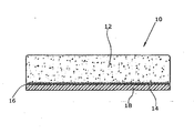
- Bottom 14 has a partially embedded in this random fiber layer 16, which is mechanically connected by gluing or welding or other ways with a single or multi-layer plastic plate 18.
- the drawn in the drawing for reasons of comprehensible representation distance between the bottom 14 of the concrete body 12 and the plastic plate 18 does not necessarily have to be present.
- This free fiber content consists of fiber ends and fiber loops.
- the fiber loops are enclosed by the cement paste when placed on the fresh concrete of a concrete sleeper in production and lead to a basic strength of the connection.
- tear strengths between the concrete and the elastic coating of about 0.3 N / mm 2 to 0.5 N / mm 2 can be achieved. These values are within the limits of the technical requirements of railway operators and their regulations.
- Hydrationssoges for frictional integration of free fiber ends in the fresh concrete leads to break-off strength of about 1.5 N / mm 2 and thus allows the assurance of high quality standards of the webs and optimal system redundancy.
Landscapes
- Engineering & Computer Science (AREA)
- Architecture (AREA)
- Civil Engineering (AREA)
- Structural Engineering (AREA)
- Mechanical Engineering (AREA)
- Road Paving Structures (AREA)
- Laminated Bodies (AREA)
- Curing Cements, Concrete, And Artificial Stone (AREA)
Description
Die Erfindung betrifft ein Betonteil mit einer Kunststoffplatte, insbesondere eine Betonschwelle, nach dem Oberbegriff des Anspruchs 1.The invention relates to a concrete part with a plastic plate, in particular a concrete sleeper, according to the preamble of claim 1.
Bei bekannten Verbundsystemen zwischen textilen Faserstrukturen und Beton, wie zum Beispiel bei der Besohlungen von Bahnschwellen aus Spannbeton bzw. Beton sind technische Lösungen bekannt, bei denen Fasern mit den Betonkonstruktionen kraftschlüssig verbunden werden.In known composite systems between textile fiber structures and concrete, such as in the Beshleungen of sleepers made of prestressed concrete or concrete technical solutions are known in which fibers are positively connected to the concrete structures.
Gemäß
Die Mehrzahl bekannter Vliese und auch anderer Verbindungsmedien wie z.B. Geotextilvliesstoffe verfügen lediglich über eingeschränkte Eigenschaften kraftschlüssiger, die Funktionalität eines Verbundes uneingeschränkt bewirkender Applikationen.The majority of known nonwovens and also other bonding media such as e.g. Geotextile nonwovens have only limited properties of non-positive, the functionality of a combination of fully effecting applications.
Kunststoffgeflechte mit steifen Faserstrukturen können beispielsweise die Mineralstrukturen im Frischbeton nicht so intensiv umverlagern, dass alle Verbindungsstrukturen vollständig im Beton eingebunden sind. Es entstehen Fehlstellen zwischen Verbundmedium und Beton, die zum Beispiel ein definiertes Elastizitätsverhalten beeinträchtigen, bei Wässerzutritt zu Pumpeffekten führen und die Gefügestruktur im Beton stören.Plastic braids with stiff fiber structures, for example, can not relocate the mineral structures in the fresh concrete so intensively that all connecting structures are completely embedded in the concrete. Defects occur between the composite medium and concrete, which, for example, impair a defined elasticity behavior, lead to pumping effects when water enters and disturb the microstructure in the concrete.
Aufgabe der Erfindung ist es, ein Betonbauteil mit einer Kunststoffplatte insbesondere als Betonschwelle mit einer unterseitigen Kunststoff-Besohlung, das/die sich einfach herstellen lässt und dessen bzw. deren Kunststoffplatte bzw. -Besohlung zuverlässig an den Betonkörper mechanisch angebunden ist.The object of the invention is to provide a concrete component with a plastic plate in particular as a concrete sleeper with a lower-side plastic soles, which / can be easily produced and whose or their plastic plate or insole is reliably connected to the concrete body mechanically.
Zur Lösung dieser Aufgabe wird mit der Erfindung ein Betonbauteil mit iener Kunststoffplatte, insbesondere eine Betonschwelle mit einer unterseitigen Kunststoff-Besohlung vorgeschlagen, das/die versehen ist mit
- einem Betonkörper, der eine Unterseite aufweist, und
- einer Kunststoffplatte, die an der Unterseite des Betonkörpers angeordnet ist,
- wobei die ein- oder mehrlagige Kunststoffplatte mit dem Betonkörper durch eine Wirrfaserschicht verbunden ist, die Fasern aufweist, welche mit der Kunststoffplatte verbunden und/oder in den Betonkörper eingebettet sind.
- a concrete body having a bottom, and
- a plastic plate, which is arranged on the underside of the concrete body,
- wherein the single or multi-ply plastic sheet is bonded to the concrete body by a random fiber layer comprising fibers bonded to the plastic sheet and / or embedded in the concrete body.
Bei diesem Betonbauteil ist erfindungsgemäß vorgesehen,
- dass die Wirrfaserschicht Fasern mit einem Durchmesser zwischen 15 µm und 50 µm sowie mit einer Dichte von 20 bis 200 Fasern je Quadratmillimeter aufweist und
- dass etwa 20 % bis 60 % der Fasern mit in den Betonkörper eingebetteten freien Enden und die eingebetteten Faserabschnitte der anderen Fasern als Schlingen ausgebildet sind,
- wobei etwa 10 % bis 60 % der in dem Beton eingebetteten freien Fäserenden relativ zur Unterseite des Betonkörpers um 30° bis 90° gekrümmt sind.
- that the random fiber layer has fibers with a diameter between 15 microns and 50 microns and with a density of 20 to 200 fibers per square millimeter, and
- that about 20% to 60% of the fibers with free ends embedded in the concrete body and the embedded fiber portions of the other fibers are formed as loops,
- wherein about 10% to 60% of the free fiber ends embedded in the concrete are curved 30 ° to 90 ° relative to the underside of the concrete body.
In vorteilhafter Weise weisen die Fasern einen im Wesentlichen kreisförmigen oder elliptischen Querschnitt auf, wobei das Seitenverhältnis der Ellipse nicht größer als 1:2 ist.Advantageously, the fibers have a substantially circular or elliptical cross-section, wherein the aspect ratio of the ellipse is not greater than 1: 2.
Gemäß einer weiteren vorteilhaften Ausgestaltung der Erfindung sind die Fasern affin zu den für den Betonkörper bei dessen Herstellung verwendeten Komponenten.According to a further advantageous embodiment of the invention, the fibers are affine to the components used for the concrete body during its production.
Es hat sich herausgestellt, dass bekannte Vliese und vliesähnliche Wirrfasermaterialien wie z.B. Filze (hergestellt durch Vernadelung, Appreturen, Faserverläufe und Faserformen) nur bedingt geeignet sind, selbstständig vom Frischbeton durch den im Abbindeprozess des Betons auftretenden Hydratationssog derart angebunden zu werden, dass die anforderungsgerechte Applikation gewährleistet ist.It has been found that known nonwovens and nonwoven-like random fiber materials such as e.g. Felts (made by needling, finishes, fiber gradients and fiber forms) are only conditionally suitable to be independently bound by the fresh concrete through the occurring during the setting process of the concrete hydration so that the application requirements is guaranteed.
Bei der Erfindung wird für die Herstellung des Betonbauteils mit Kunststoffplatte bzw. der Betonschwelle mit unterseitiger Kunststoff-Besohlung als mechanische Verbindung zwischen diesen beiden Elementen eine spezielle Fasern aufweisende Wirrfaserschicht verwendet, so dass die Faserenden in Folge des Hydratationssoges des Betons bei dessen Abbinden in Kapillar- und/oder Gelporen des Betons gelangen und im abgebundenen Zustand des Betons in diesem gehalten sind. Dabei kann die Wirrfaserschicht auf ihrer der Unterseite der Betonschwelle abgewandten Seite mit einer ein- oder mehrlagigen Kunststoffplatte verbunden werden, und zwar entweder vor oder nach der Verbindung der Wirrfaserschicht mit dem Betonkörper.In the invention, a special fiber-containing random fiber layer is used for the production of the concrete component with plastic plate or the concrete sleeper with bottom plastic reinforcement as a mechanical connection between these two elements, so that the fiber ends as a result of the Hydration Suction of the concrete in its capillary and / or gel pores of the concrete and are held in the set condition of the concrete in this. In this case, the random fiber layer can be connected on its side facing away from the underside of the concrete sleeper with a single or multi-layer plastic plate, either before or after the connection of the random fiber layer with the concrete body.
Aus der Erkenntnis, dass Frischbeton unter definierbaren Rezeptur- und Verarbeitungsbedingungen einen Hydratationssog entwickelt, sind also erfindunsgemäß die Wirrfaserschicht und der Beton so aufeinander abgestimmt, dass der Hydratationssog die verbindenden Faserstrukturen in den Frischbeton einsaugt.From the realization that fresh concrete under definable formulation and processing conditions developed a Hydrratationssog, therefore, according to the invention the random fiber layer and the concrete are coordinated so that the hydration suction sucks the connecting fiber structures in the fresh concrete.
Zur technischen Nutzung dieses Hydratationssoges sind die nachfolgenden betontechnologischen, zementchemischen, textiltechnischen und applikationsspezifischen Kriterien in ihrem zusammenhängenden Wirkprozess als erfindungsgemäße Lösung definiert.For the technical use of this hydration soot, the following concrete technology, cement chemical, textile-technical and application-specific criteria are defined in their coherent active process as a solution according to the invention.
Die Hydratation als Reaktion zwischen Wasser und Zement bewirkt die Bildung des Zementsteins. Einige der Hauptbestandteile des Zements, die beim Brennen der Ausgangsstoffe entstehen und in der Klinkerphase eine weitere Modifizierung erfahren, bewirken unterschiedliche Reaktionsabläufe zwischen dem Anmachwasser und eben diesen Zementbestandteilen.Hydration as a reaction between water and cement causes the formation of cementum. Some of the main constituents of the cement, which are formed when the starting materials are burned and undergo further modification in the clinker phase, cause different reaction processes between the mixing water and precisely these cement constituents.
Insbesondere bewirken Tricalciumaluminat und Tricalciumsilicat eine hohe Reaktionsgeschwindigkeit und die Festigkeitsentwicklung des Zementsteins. Der Calciumsulfatanteil (Gips) beeinflusst bzw. verzögert die Wirkung des Tricalciumaluminats. Erfindungsgemäß ist bei der Eignungsprüfung für die Betonrezeptierung durch die Wahl der Zementsorte das Verfahren zu modifizieren bzw. zu optimieren.In particular, tricalcium aluminate and tricalcium silicate cause a high reaction rate and strength development of the cement paste. The calcium sulfate content (gypsum) influences or delays the action of tricalcium aluminate. According to the invention, in the suitability test for the concrete formulation by the choice of cement type to modify or optimize the process.
Der Frischbeton erfährt durch einen hohen Gehalt an Tricalciumaluminat und dessen Zusammenwirken mit den Eigenschaften der anderen Klinkerbestandteile (im Wesentlichen Tricalciumsilikat, Dlcalciumsilikat und Tetracalciumaluminatferrit) des noch nicht im Abbinde- und Erhärtungsstadium befindlichen Frischbetons die Eigenschaft, feine faser- und folienartige Calciumsilicathydrate und kleine Kristalle aus Calciumhydroxyd zu bilden.The fresh concrete is characterized by a high content of tricalcium and its interaction with the properties of other clinker constituents (essentially tricalcium silicate, Dlcalciumsilikat and Tetracalciumaluminatferrit) of not yet in the setting and hardening stage fresh concrete property, fine fiber and foil-like calcium silicate hydrates and small crystals Calcium hydroxide to form.
Weiterhin entstehen bei Reaktion der Aluminate mit Calciumsulfat die Calciumaluminatsulfathydrate als nadelförmige Trisulfate, das so genannte Ettringit.Furthermore, upon reaction of the aluminates with calcium sulfate, the calcium aluminate sulfate hydrates are formed as acicular trisulfates, the so-called ettringite.
Die Reaktion des Tricalciumaluminats mit den Calciumsulfaten ist mit einer Volumenvergrößerung verbunden, die im noch nicht erstarrten Beton insoweit folgenlos ist, als ein Ettringittreiben nicht entsteht.The reaction of the tricalcium aluminate with the calcium sulfates is associated with an increase in volume, which is inconsequential in the not yet solidified concrete, as an Ettringittreiben does not arise.
Die Volumenvergrößerung bewirkt jedoch in dem in der Bildung befindlichen Zementgel und den darin enthaltenen Kapillar- und Gelporen den als solchen bezeichneten Hydratationssog.However, the increase in volume causes in the formation of the cement gel and the capillary and gel pores therein the so-called Hydrratathssog.
Dieser Hydratationssog wird, soweit bekannt, in keiner bekannten Betontechnologie als verfahrenstechnischer Vorteil genutzt. Ausschließlich bei der Applikation von Nachbehandlungsmitteln im Betonstraßenbau ist die Nutzung ähnliche Effekte bekannt.This Hydrratationsssog is, as far as known, used in any known concrete technology as process engineering advantage. The use of similar effects is known only in the application of aftertreatment agents in concrete road construction.
Erfindungsgemäß wird für die gezielte Einbindung von Fasern in die Frischbetonoberfläche der betontechnologische Hydratationssog technisch und wirtschaftlich genutzt.According to the concrete hydrological Hydratationssog is used technically and economically for the targeted incorporation of fibers in the fresh concrete surface.
Die Gelporen sind mit einem Anteil von vorzugsweise etwa 25 % des Gelvolumens und einem Porenradius von 10-7 mm bis 10-5 mm geeignet, Fasern eines auf den Frischbeton aufgelegten Materials anzusaugen, wenn diese Fasern gegenüber den Kapillar- und Gelporen eine konkludente Struktur und Beschaffenheit aufweisen. Die Kapillar- und Gelporen weisen im Allgemeinen eine zylindrische Form auf und verjüngen sich mit zunehmender Porentiefe zu so genannten Flaschenporen. Die zur Nutzung des Hydratationssoges geeigneten Fasern müssen dahingehend konkludent sein, dass sie sowohl im zylindrischen, als auch im verjüngenden Teil der Poren erfindungsgemäß eindringen können. Die Kapillarporen mit Porenradien zwischen insbesondere 10-5 mm bis 10-1 mm ergänzen die Gelporen in der Porengröße nahezu ohne technisch nachteilig wirkenden Übergang.The gel pores, with a proportion of preferably about 25% of the gel volume and a pore radius of 10 -7 mm to 10 -5 mm are suitable for absorbing fibers of a material placed on the fresh concrete, if these fibers have an implied structure over the capillary and gel pores Texture. The capillary and gel pores generally have a cylindrical shape and taper with increasing pore depth to so-called bottle pores. The fibers which are suitable for use of the hydration suction must be conclusive in such a way that they can penetrate both in the cylindrical and in the tapered part of the pores according to the invention. The capillary pores with pore radii between in particular 10 -5 mm to 10 -1 mm complement the gel pores in the pore size almost without technically disadvantageous transition.
Bei den am Beispiel einer Schwellenbesohlung verwendeten Geotextilien wird eine Wirrfaserstruktur aus PE bzw. PET mit Fäserdurchmessern von insbesondere ca. 20 µm bis 40 µm verwendet. Diese Faserdurchmesser und die verwendete Faserdichte von zweckmäßigerweise 40 bis 130 Fäden/mm2 bietet die für das Ansaugen der Fasern erforderliche Kompatibilität zwischen Hydratationssog, Kapillar- und Gelporen, Faserdurchmesser und Faserdichte.In the case of the geotextiles used on the example of a sleeper padding, a tangled fiber structure of PE or PET with fiber diameters of, in particular, about 20 μm to 40 μm is used. These fiber diameters and the fiber density used, suitably 40 to 130 threads / mm 2, provide the compatibility between hydration suction, capillary and gel pores, fiber diameter and fiber density required for the aspiration of the fibers.
Als weitere Bedingungen zur Wirksamkeit der eigenständigen Aufnahme von Fasern definierter Faserstärke und Faserdichte infolge Hydratationssog sind die freie Faserlänge, die geometrische Form der Fasern und ihre Querschnittsgestaltung sowie deren Ausrichtung und Affinität gegenüber dem Anmachwasser sowie dem Zementgel erfindungsgemäß definierbar. Dies betrifft zum Beispiel solche Geotextile oder andere Wirrfaserstrukturen bzw. Fasermaterialien, die in deren Herstellungsprozess hydrophob ausgestattet werden oder/und durch die Verdüsung einen der Hydratationsporengeometrie nicht verträglichen z.B. rechteckigen Querschnitt haben.As further conditions for the effectiveness of the independent absorption of fibers of defined fiber strength and fiber density as a result of Hydrratssssog are the free fiber length, the geometric shape of the fibers and their cross-sectional configuration as well as their orientation and affinity for the mixing water and the cement gel inventively definable. This applies, for example, to those geotextiles or other random fiber structures or fiber materials which are rendered hydrophobic in their production process and / or which, due to the atomization, have a cross-section which is not compatible with the hydration pore geometry.
Danach sollten die für die Einbindung in den Beton verfügbaren Fasern in einem definierten Anteil von vorzugsweise 20% bis 50 % freie Enden besitzen. Nur ein begrenzter Anteil von vorzugsweise weniger als 50 % der Fasern sollte als Schlinge ausgebildet sein. Die freien Enden der Fasern sollten nicht ausschließlich gerade verlaufen; ein Anteil von z.B. 10 % bis 60 % sollte derart gekrümmt sein, dass der Krümmungswinkel mindestens 30°, jedoch nicht mehr als 90° beträgt.Thereafter, the fibers available for incorporation into the concrete should have free ends in a defined proportion of preferably 20% to 50%. Only a limited proportion of preferably less than 50% of the fibers should be formed as a loop. The free ends of the fibers should not be exclusively straight; a proportion of e.g. 10% to 60% should be curved such that the angle of curvature is at least 30 ° but not more than 90 °.
Der Faserquerschnitt sollte kreisrund bis elliptisch sein, wobei das Seitenverhältnis der Ellipse nicht größer als 1:2 sein sollte.The fiber cross-section should be circular to elliptical, with the aspect ratio of the ellipse not exceeding 1: 2.
Die Fasern selbst sollten von Rückständen der Faser- oder Gewirkherstellung befreit sein, die eine Affinität zum Zementleim, zum Gel oder zum Anmachwasser beeinträchtigen könnten. Als Materialien für die Fasern kommen die bekannten Kunststofffasermaterialien (z.B. Thermoplaste wie PE oder PET), Metalle (Metallfasern) oder auch nachwachsende bzw. pflanzliche Rohstoffe in Frage.The fibers themselves should be freed from residues of fiber or knit making which could affect affinity for cement paste, gel or make-up water. Suitable materials for the fibers are the known plastic fiber materials (for example thermoplastics such as PE or PET), metals (metal fibers) or also renewable or vegetable raw materials.
Nachfolgend wird anhand der Zeichnung, die einen Querschnitt durch eine Betonschwelle mit unterseitig über eine Wirrfaserschicht mechanisch angebundener elastischer Kunststoffplatte zeigt, ein Ausführungsbeispiel der Erfindung näher erläutert.An exemplary embodiment of the invention will be explained in more detail below with reference to the drawing, which shows a cross section through a concrete sleeper with an elastic plastic plate mechanically bonded to the underside via a random fiber layer.
In der Zeichnung ist beispielhaft eine Betonschwelle 10 mit einem bewehrten, schlaff bewehrten oder nicht bewehrten Beton-(voll-)körper 12, der an seinerIn the drawing, for example, a
Unterseite 14 eine teilweise in diese eingebettete Wirrfaserschicht 16 aufweist, die durch Verkleben oder Verschweißen oder auf andere Art mechanisch mit einer ein- oder mehrlagigen Kunststoffplatte 18 verbunden ist. Der in der Zeichnung aus Gründen der verständlicheren Darstellung eingezeichnete Abstand zwischen der Unterseite 14 des Betonkörpers 12 und der Kunststoffplatte 18 braucht nicht notwendigerweise vorhanden zu sein.
Bei den als Schwellenbesohlung bezeichneten unterseitigen elastischen Beschichtungen von Bahnschwellen aus Beton bzw. Spannbeton werden in die elastischen Beschichtungsmaterialien Wirrfaserschichten mit definierten Fasereigenschaften eingeschmolzen.In the below-mentioned elastic coatings of concrete sleepers or prestressed concrete sleepers, which are called threshold sleepers, random fiber layers with defined fiber properties are melted into the elastic coating materials.
Diese Wirrfaserschichten verfügen nach einseitig etwa hälftiger Einbindung in die elastischen Materialien über einen nicht eingebundenen, von den elastischen Materialien aufragenden Faseranteil zur Anbindung an die Betonschwellen.These random fiber layers, after being integrated on one side into the elastic materials by about one-half, have a non-bonded fiber portion that rises up from the elastic materials for connection to the concrete sleepers.
Dieser freie Faseranteil besteht aus Faserenden und Faserschlingen. Die Faserschlingen werden beim Auflegen auf den Frischbeton einer in der Fertigung befindlichen Betonschwelle vom Zementleim umschlossen und führen zu einer Grundfestigkeit der Anbindung.This free fiber content consists of fiber ends and fiber loops. The fiber loops are enclosed by the cement paste when placed on the fresh concrete of a concrete sleeper in production and lead to a basic strength of the connection.
Mit dieser Grundfestigkeit lassen sich Abreißfestigkeiten zwischen dem Beton und der elastischen Beschichtung von etwa 0,3 N/mm2 bis 0,5 N/mm2 erreichen. Diese Werte liegen im Grenzbereich der technischen Anforderungen von Bahnbetreibern und deren Regelwerken.With this basic strength, tear strengths between the concrete and the elastic coating of about 0.3 N / mm 2 to 0.5 N / mm 2 can be achieved. These values are within the limits of the technical requirements of railway operators and their regulations.
Die technische Nutzung des Hydratationssoges zur kraftschlüssigen Einbindung freier Faserenden in den Frischbeton führt zu Abreißfestigkeiten von über 1,5 N/mm2 und ermöglicht damit die Sicherung hoher Qualitätsansprüche der Bahnen und eine optimale Systemredundanz.The technical use of the Hydrationssoges for frictional integration of free fiber ends in the fresh concrete leads to break-off strength of about 1.5 N / mm 2 and thus allows the assurance of high quality standards of the webs and optimal system redundancy.
Bei Faserdurchmessern von ca. 25 µm bis ca. 40 µm und einer Faserdichte zwischen 40 und 130 Fasern je mm2 sowie der Verwendung calciumsulfatarmer Zemente werden die freien Faserenden in den in der Bildung befindlichen Ettringit unter Nutzung des Hydratationssoges angesaugt. Die im Umfeld der hierdurch entstehenden Matrix aus Fasern und Zementleim unter atmosphärischem Druck befindliche Luft dient nur bedingt als Rezipient. Ein weiterer technischer Zusammenhang besteht zur Hydratationsenergie. Damit besteht auch die Möglichkeit unter Bedingungen geminderten Luftdrucks (z.B. Vakuumbeton) nach diesem Prinzip elastische Kunststoffe an Betonschwellen zu applizieren.With fiber diameters of about 25 microns to about 40 microns and a fiber density between 40 and 130 fibers per mm 2 and the use of calcium sulfate-less cements, the free fiber ends are sucked into the Ettringit in formation using the Hydratrationsssoges. The air in the vicinity of the resulting matrix of fibers and cement paste under atmospheric pressure only serves as a recipient. Another technical context is the hydration energy. Thus there is also the possibility under conditions of reduced air pressure (eg vacuum concrete) to apply elastic plastics to concrete sleepers according to this principle.
Die Erfindung wurde vorstehend anhand einer Betonschwelle als Anwendungsfall eines Betonbauteils erläutert. Es versteht sich von selbst, dass die Erfindung damit aber auf Betonschwellen nicht beschränkt ist, sondern Anwendung überall dort findet, wo der Betonkörper eines Betonbauteils mit einer Kunststoffplatte mechanisch verbunden werden muss.The invention has been explained above with reference to a concrete sleeper as an application of a concrete component. It goes without saying that the invention is therefore not limited to concrete sleepers, but application finds everywhere where the concrete body of a concrete component with a plastic plate must be mechanically connected.
Claims (3)
- A concrete component comprising a plastic panel, particularly a concrete sleeper with a plastic footing on its lower face, comprising:- a concrete body (12) having a lower face (14), and- a plastic panel (18) arranged on the lower face (14) of the concrete body (12),- the single-layer or multi-layer plastic panel (18) being connected to the concrete body (12) by a random fiber layer (16) which comprises fibers connected to the plastic panel (18) and/or embedded in the concrete body (12),
characterized in- that the random fiber layer (16) comprises fibers having a diameter from 15 µm to 50 µm and a density from 20 to 200 fibers per square millimeter, and- that approximately 20% to 60% of the fibers have their free ends embedded in the concrete body (12) and the embedded fiber sections of the other fibers are designed as loops,- approximately 10% to 60% of said free fiber ends embedded in the concrete being curved by 30° to 90° relative to the lower face (14) of the concrete body (12). - The concrete component according to claim 1, characterized in that the fibers have a substantially circular or elliptic cross section, the aspect ratio of the ellipse being not larger than 1:2.
- The concrete component according to claim 1 or 2, characterized in that the fibers are affine to the components used for the concrete body (12) when producing the latter.
Priority Applications (4)
| Application Number | Priority Date | Filing Date | Title |
|---|---|---|---|
| SI201130371T SI2545219T1 (en) | 2010-03-12 | 2011-03-11 | Concrete element with an underside plastic sole |
| PL11710720T PL2545219T3 (en) | 2010-03-12 | 2011-03-11 | Concrete element with an underside plastic sole |
| EP20110710720 EP2545219B1 (en) | 2010-03-12 | 2011-03-11 | Concrete element with an underside plastic sole |
| HRP20150045TT HRP20150045T1 (en) | 2010-03-12 | 2015-01-13 | Concrete element with an underside plastic sole |
Applications Claiming Priority (4)
| Application Number | Priority Date | Filing Date | Title |
|---|---|---|---|
| EP10156352 | 2010-03-12 | ||
| EP10156347 | 2010-03-12 | ||
| PCT/EP2011/053709 WO2011110669A1 (en) | 2010-03-12 | 2011-03-11 | Concrete sleeper and method for the production thereof |
| EP20110710720 EP2545219B1 (en) | 2010-03-12 | 2011-03-11 | Concrete element with an underside plastic sole |
Publications (2)
| Publication Number | Publication Date |
|---|---|
| EP2545219A1 EP2545219A1 (en) | 2013-01-16 |
| EP2545219B1 true EP2545219B1 (en) | 2014-11-05 |
Family
ID=44146636
Family Applications (1)
| Application Number | Title | Priority Date | Filing Date |
|---|---|---|---|
| EP20110710720 Active EP2545219B1 (en) | 2010-03-12 | 2011-03-11 | Concrete element with an underside plastic sole |
Country Status (12)
| Country | Link |
|---|---|
| US (1) | US20130059144A1 (en) |
| EP (1) | EP2545219B1 (en) |
| CN (1) | CN102906335B (en) |
| DK (1) | DK2545219T3 (en) |
| ES (1) | ES2528144T3 (en) |
| HR (1) | HRP20150045T1 (en) |
| PL (1) | PL2545219T3 (en) |
| PT (1) | PT2545219E (en) |
| RS (1) | RS53765B1 (en) |
| RU (1) | RU2557440C2 (en) |
| SI (1) | SI2545219T1 (en) |
| WO (1) | WO2011110669A1 (en) |
Cited By (2)
| Publication number | Priority date | Publication date | Assignee | Title |
|---|---|---|---|---|
| WO2019201761A1 (en) | 2018-04-19 | 2019-10-24 | Rst-Rail Systems And Technologies Gmbh | Sleeper pad for dry concrete |
| DE102022134100A1 (en) | 2022-12-20 | 2024-06-20 | Het Elastomertechnik Gmbh | Method for producing sleeper pads for a railway track with ballast bedding |
Families Citing this family (11)
| Publication number | Priority date | Publication date | Assignee | Title |
|---|---|---|---|---|
| AT513946B1 (en) * | 2013-01-17 | 2014-12-15 | Getzner Werkstoffe Holding Gmbh | sleeper |
| CN103161099A (en) * | 2013-03-29 | 2013-06-19 | 无锡恒畅铁路轨枕有限公司 | Concrete sleeper |
| CN103194939A (en) * | 2013-03-29 | 2013-07-10 | 无锡恒畅铁路轨枕有限公司 | Concrete sleeper |
| CN103194938A (en) * | 2013-03-29 | 2013-07-10 | 无锡恒畅铁路轨枕有限公司 | Concrete sleeper |
| CN103147367A (en) * | 2013-03-29 | 2013-06-12 | 无锡恒畅铁路轨枕有限公司 | Concrete sleeper |
| CN103147364A (en) * | 2013-03-29 | 2013-06-12 | 无锡恒畅铁路轨枕有限公司 | Concrete sleeper |
| CN103161100A (en) * | 2013-03-29 | 2013-06-19 | 无锡恒畅铁路轨枕有限公司 | High-strength concrete sleeper |
| DE102014112326A1 (en) * | 2014-08-27 | 2016-03-03 | GKT Gummi- und Kunststofftechnik Fürstenwalde GmbH | Sill and method for making a Schwellensohle |
| DE102017116093A1 (en) * | 2017-07-18 | 2019-01-24 | Dätwyler Sealing Technologies Deutschland Gmbh | Sealing profile for embedding in a molded part of hardenable material |
| CA3090239A1 (en) * | 2018-01-31 | 2019-08-08 | 3M Innovative Properties Company | Article including composite layer and method of making the article |
| JP6674504B2 (en) * | 2018-06-07 | 2020-04-01 | 株式会社イノアックコーポレーション | Sleeper pad |
Family Cites Families (9)
| Publication number | Priority date | Publication date | Assignee | Title |
|---|---|---|---|---|
| US6426029B1 (en) * | 1995-10-10 | 2002-07-30 | Donald R. Hiscock | Lamination between plastic resins and cement |
| US7192643B2 (en) * | 2001-08-22 | 2007-03-20 | 3M Innovative Properties Company | Toughened cementitious composites |
| EP1298252B2 (en) * | 2001-10-01 | 2011-06-01 | RST-Rail Systems and Technologies GmbH | Sleeper with bottom coating |
| DE10304768B3 (en) * | 2003-02-05 | 2004-08-05 | Rst-Rail Systems And Technologies Gmbh | Railway sleeper for railways comprises a sleeper body, an elastic plastic layer formed on the lower side of the sleeper, and a fiber layer on the lower side of the plastic layer facing away from the sleeper body |
| DE102004063636A1 (en) * | 2004-12-31 | 2006-07-13 | Pfleiderer Infrastrukturtechnik Gmbh & Co. Kg | Concrete sleepers for high dynamic loads |
| FR2906269B1 (en) * | 2006-09-22 | 2008-12-19 | Alstom Transport Sa | RAILWAY TRAVERSE |
| AT506529B1 (en) * | 2008-03-06 | 2010-05-15 | Getzner Werkstoffe Holding Gmbh | THRESHOLD SOLE |
| RU76649U1 (en) * | 2008-04-17 | 2008-09-27 | Открытое Акционерное Общество "Российские Железные Дороги" | REINFORCED CONCRETE BEDROOM WITH ELASTIC GASKETS ON THE SOLE |
| FR2935399B1 (en) * | 2008-09-02 | 2012-10-12 | Sateba Systeme Vagneux | VISCOELASTIC SOLE, ASSEMBLY COMPRISING A BLOCK AND AN ABOVE SOLE, AND CORRESPONDING MANUFACTURING METHODS. |
-
2011
- 2011-03-11 PL PL11710720T patent/PL2545219T3/en unknown
- 2011-03-11 CN CN201180013641.5A patent/CN102906335B/en active Active
- 2011-03-11 RU RU2012143479/11A patent/RU2557440C2/en active
- 2011-03-11 RS RS20150013A patent/RS53765B1/en unknown
- 2011-03-11 WO PCT/EP2011/053709 patent/WO2011110669A1/en active Application Filing
- 2011-03-11 SI SI201130371T patent/SI2545219T1/en unknown
- 2011-03-11 DK DK11710720.1T patent/DK2545219T3/en active
- 2011-03-11 US US13/634,351 patent/US20130059144A1/en not_active Abandoned
- 2011-03-11 ES ES11710720.1T patent/ES2528144T3/en active Active
- 2011-03-11 PT PT11710720T patent/PT2545219E/en unknown
- 2011-03-11 EP EP20110710720 patent/EP2545219B1/en active Active
-
2015
- 2015-01-13 HR HRP20150045TT patent/HRP20150045T1/en unknown
Cited By (3)
| Publication number | Priority date | Publication date | Assignee | Title |
|---|---|---|---|---|
| WO2019201761A1 (en) | 2018-04-19 | 2019-10-24 | Rst-Rail Systems And Technologies Gmbh | Sleeper pad for dry concrete |
| DE102022134100A1 (en) | 2022-12-20 | 2024-06-20 | Het Elastomertechnik Gmbh | Method for producing sleeper pads for a railway track with ballast bedding |
| WO2024132642A1 (en) | 2022-12-20 | 2024-06-27 | Het Elastomertechnik Gmbh | Process for producing under-sleeper pads for a ballasted track |
Also Published As
| Publication number | Publication date |
|---|---|
| PL2545219T3 (en) | 2015-04-30 |
| SI2545219T1 (en) | 2015-04-30 |
| RS53765B1 (en) | 2015-06-30 |
| DK2545219T3 (en) | 2015-01-26 |
| CN102906335A (en) | 2013-01-30 |
| HRP20150045T1 (en) | 2015-05-08 |
| EP2545219A1 (en) | 2013-01-16 |
| WO2011110669A1 (en) | 2011-09-15 |
| RU2012143479A (en) | 2014-05-10 |
| RU2557440C2 (en) | 2015-07-20 |
| US20130059144A1 (en) | 2013-03-07 |
| CN102906335B (en) | 2015-08-05 |
| PT2545219E (en) | 2015-02-05 |
| ES2528144T3 (en) | 2015-02-04 |
Similar Documents
| Publication | Publication Date | Title |
|---|---|---|
| EP2545219B1 (en) | Concrete element with an underside plastic sole | |
| DE112014003893T5 (en) | A sound-absorbing microparticle plate and its production process | |
| EP0258734B1 (en) | Layered building panel and method of manufacturing it | |
| DE102005024408A1 (en) | Producing fiber reinforced foam materials for aircraft involves engaging through hole from first surface to engage at least one fiber bundle and pulling bundle(s) into through hole in foam material | |
| DE3445396A1 (en) | METHOD FOR APPLYING A CORROSION-RESISTANT SYNTHETIC COATING TO THE SURFACE OF A CONCRETE CONSTRUCTION | |
| EP4035857B1 (en) | Method for the production of reinforced 3d printed concrete or mortar-based objects | |
| DE4026943C1 (en) | ||
| DE102015119700A1 (en) | Process for conditioning the surfaces of pultruded and / or otherwise combined by resins or adhesive carbon fibers into carbon fiber profiles or carbon fiber surfaces and arrangement for carrying out the method | |
| EP2870304B1 (en) | Fibre-reinforced mineral building material | |
| WO1992022715A1 (en) | Mineral wool moulding | |
| DE69725284T2 (en) | REINFORCEMENT FOR CONCRETE PARTS AND REINFORCED CONCRETE PARTS | |
| EP2758610B1 (en) | Method for producing a construction panel | |
| EP2374769A1 (en) | Aggregate for constructing an acoustic absorption layer of a noise insulation device and noise insulation device | |
| DE102011013739A1 (en) | building board | |
| EP3266605A1 (en) | Construction panel with reinforcement fabric and method for its manufacture | |
| DE102012101075A1 (en) | Sheet-like semi-finished product for panel, has substrate, upper capillary structure layer containing hardened coating material, on one surface of substrate, and reinforcing layer containing carrier material on other side of substrate | |
| DE102012001055A1 (en) | component | |
| DE1000144B (en) | Plaster supports, especially for ceilings and walls | |
| EP1991734A1 (en) | Construction sector membrane | |
| WO2018234298A1 (en) | Film adhesive and method for producing same | |
| EP1936064B1 (en) | Joint strip | |
| DE20102039U1 (en) | Support element and support element arrangement, in particular for concrete structures and concrete components | |
| DE102005053104A1 (en) | building board | |
| DE102023200860A1 (en) | Combination for the production of a reinforced bed joint mortar layer of a reinforced masonry, such bed joint mortar layer, reinforced masonry with such bed joint mortar layer and method for producing such bed joint mortar layer and a reinforced masonry | |
| EP4238747A1 (en) | Method for applying a material to a fibre composite component |
Legal Events
| Date | Code | Title | Description |
|---|---|---|---|
| PUAI | Public reference made under article 153(3) epc to a published international application that has entered the european phase |
Free format text: ORIGINAL CODE: 0009012 |
|
| 17P | Request for examination filed |
Effective date: 20120926 |
|
| AK | Designated contracting states |
Kind code of ref document: A1 Designated state(s): AL AT BE BG CH CY CZ DE DK EE ES FI FR GB GR HR HU IE IS IT LI LT LU LV MC MK MT NL NO PL PT RO RS SE SI SK SM TR |
|
| DAX | Request for extension of the european patent (deleted) | ||
| GRAP | Despatch of communication of intention to grant a patent |
Free format text: ORIGINAL CODE: EPIDOSNIGR1 |
|
| GRAJ | Information related to disapproval of communication of intention to grant by the applicant or resumption of examination proceedings by the epo deleted |
Free format text: ORIGINAL CODE: EPIDOSDIGR1 |
|
| INTG | Intention to grant announced |
Effective date: 20140401 |
|
| GRAP | Despatch of communication of intention to grant a patent |
Free format text: ORIGINAL CODE: EPIDOSNIGR1 |
|
| INTC | Intention to grant announced (deleted) | ||
| GRAJ | Information related to disapproval of communication of intention to grant by the applicant or resumption of examination proceedings by the epo deleted |
Free format text: ORIGINAL CODE: EPIDOSDIGR1 |
|
| GRAP | Despatch of communication of intention to grant a patent |
Free format text: ORIGINAL CODE: EPIDOSNIGR1 |
|
| INTG | Intention to grant announced |
Effective date: 20140506 |
|
| INTG | Intention to grant announced |
Effective date: 20140528 |
|
| GRAS | Grant fee paid |
Free format text: ORIGINAL CODE: EPIDOSNIGR3 |
|
| GRAA | (expected) grant |
Free format text: ORIGINAL CODE: 0009210 |
|
| AK | Designated contracting states |
Kind code of ref document: B1 Designated state(s): AL AT BE BG CH CY CZ DE DK EE ES FI FR GB GR HR HU IE IS IT LI LT LU LV MC MK MT NL NO PL PT RO RS SE SI SK SM TR |
|
| REG | Reference to a national code |
Ref country code: GB Ref legal event code: FG4D Free format text: NOT ENGLISH |
|
| REG | Reference to a national code |
Ref country code: CH Ref legal event code: EP |
|
| REG | Reference to a national code |
Ref country code: AT Ref legal event code: REF Ref document number: 694745 Country of ref document: AT Kind code of ref document: T Effective date: 20141115 |
|
| REG | Reference to a national code |
Ref country code: IE Ref legal event code: FG4D Free format text: LANGUAGE OF EP DOCUMENT: GERMAN |
|
| REG | Reference to a national code |
Ref country code: DE Ref legal event code: R096 Ref document number: 502011004878 Country of ref document: DE Effective date: 20141224 |
|
| REG | Reference to a national code |
Ref country code: HR Ref legal event code: TUEP Ref document number: P20150045 Country of ref document: HR |
|
| REG | Reference to a national code |
Ref country code: RO Ref legal event code: EPE |
|
| REG | Reference to a national code |
Ref country code: DK Ref legal event code: T3 Effective date: 20150121 |
|
| REG | Reference to a national code |
Ref country code: NL Ref legal event code: T3 Ref country code: ES Ref legal event code: FG2A Ref document number: 2528144 Country of ref document: ES Kind code of ref document: T3 Effective date: 20150204 |
|
| REG | Reference to a national code |
Ref country code: PT Ref legal event code: SC4A Free format text: AVAILABILITY OF NATIONAL TRANSLATION Effective date: 20150115 |
|
| REG | Reference to a national code |
Ref country code: SE Ref legal event code: TRGR |
|
| REG | Reference to a national code |
Ref country code: SK Ref legal event code: T3 Ref document number: E 17922 Country of ref document: SK |
|
| REG | Reference to a national code |
Ref country code: GR Ref legal event code: EP Ref document number: 20150400088 Country of ref document: GR Effective date: 20150220 |
|
| REG | Reference to a national code |
Ref country code: NO Ref legal event code: T2 Effective date: 20141105 |
|
| REG | Reference to a national code |
Ref country code: EE Ref legal event code: FG4A Ref document number: E010313 Country of ref document: EE Effective date: 20150120 |
|
| PG25 | Lapsed in a contracting state [announced via postgrant information from national office to epo] |
Ref country code: IS Free format text: LAPSE BECAUSE OF FAILURE TO SUBMIT A TRANSLATION OF THE DESCRIPTION OR TO PAY THE FEE WITHIN THE PRESCRIBED TIME-LIMIT Effective date: 20150305 |
|
| REG | Reference to a national code |
Ref country code: PL Ref legal event code: T3 |
|
| REG | Reference to a national code |
Ref country code: HR Ref legal event code: T1PR Ref document number: P20150045 Country of ref document: HR |
|
| PG25 | Lapsed in a contracting state [announced via postgrant information from national office to epo] |
Ref country code: CY Free format text: LAPSE BECAUSE OF FAILURE TO SUBMIT A TRANSLATION OF THE DESCRIPTION OR TO PAY THE FEE WITHIN THE PRESCRIBED TIME-LIMIT Effective date: 20141105 |
|
| REG | Reference to a national code |
Ref country code: HU Ref legal event code: AG4A Ref document number: E022932 Country of ref document: HU |
|
| REG | Reference to a national code |
Ref country code: DE Ref legal event code: R097 Ref document number: 502011004878 Country of ref document: DE |
|
| PLBE | No opposition filed within time limit |
Free format text: ORIGINAL CODE: 0009261 |
|
| STAA | Information on the status of an ep patent application or granted ep patent |
Free format text: STATUS: NO OPPOSITION FILED WITHIN TIME LIMIT |
|
| 26N | No opposition filed |
Effective date: 20150806 |
|
| PG25 | Lapsed in a contracting state [announced via postgrant information from national office to epo] |
Ref country code: MC Free format text: LAPSE BECAUSE OF FAILURE TO SUBMIT A TRANSLATION OF THE DESCRIPTION OR TO PAY THE FEE WITHIN THE PRESCRIBED TIME-LIMIT Effective date: 20141105 |
|
| REG | Reference to a national code |
Ref country code: FR Ref legal event code: PLFP Year of fee payment: 6 |
|
| PG25 | Lapsed in a contracting state [announced via postgrant information from national office to epo] |
Ref country code: MT Free format text: LAPSE BECAUSE OF FAILURE TO SUBMIT A TRANSLATION OF THE DESCRIPTION OR TO PAY THE FEE WITHIN THE PRESCRIBED TIME-LIMIT Effective date: 20141105 |
|
| REG | Reference to a national code |
Ref country code: FR Ref legal event code: PLFP Year of fee payment: 7 |
|
| PGFP | Annual fee paid to national office [announced via postgrant information from national office to epo] |
Ref country code: GR Payment date: 20170321 Year of fee payment: 7 |
|
| PG25 | Lapsed in a contracting state [announced via postgrant information from national office to epo] |
Ref country code: SM Free format text: LAPSE BECAUSE OF FAILURE TO SUBMIT A TRANSLATION OF THE DESCRIPTION OR TO PAY THE FEE WITHIN THE PRESCRIBED TIME-LIMIT Effective date: 20141105 |
|
| REG | Reference to a national code |
Ref country code: FR Ref legal event code: PLFP Year of fee payment: 8 |
|
| PG25 | Lapsed in a contracting state [announced via postgrant information from national office to epo] |
Ref country code: AL Free format text: LAPSE BECAUSE OF FAILURE TO SUBMIT A TRANSLATION OF THE DESCRIPTION OR TO PAY THE FEE WITHIN THE PRESCRIBED TIME-LIMIT Effective date: 20141105 |
|
| PG25 | Lapsed in a contracting state [announced via postgrant information from national office to epo] |
Ref country code: GR Free format text: LAPSE BECAUSE OF NON-PAYMENT OF DUE FEES Effective date: 20181003 |
|
| REG | Reference to a national code |
Ref country code: HR Ref legal event code: ODRP Ref document number: P20150045 Country of ref document: HR Payment date: 20190305 Year of fee payment: 9 |
|
| REG | Reference to a national code |
Ref country code: HR Ref legal event code: ODRP Ref document number: P20150045 Country of ref document: HR Payment date: 20200227 Year of fee payment: 10 |
|
| REG | Reference to a national code |
Ref country code: EE Ref legal event code: HC1A Ref document number: E010313 Country of ref document: EE |
|
| REG | Reference to a national code |
Ref country code: HR Ref legal event code: ODRP Ref document number: P20150045 Country of ref document: HR Payment date: 20210903 Year of fee payment: 11 |
|
| REG | Reference to a national code |
Ref country code: HR Ref legal event code: ODRP Ref document number: P20150045 Country of ref document: HR Payment date: 20220301 Year of fee payment: 12 |
|
| REG | Reference to a national code |
Ref country code: HR Ref legal event code: ODRP Ref document number: P20150045 Country of ref document: HR Payment date: 20230302 Year of fee payment: 13 |
|
| P01 | Opt-out of the competence of the unified patent court (upc) registered |
Effective date: 20230526 |
|
| PGFP | Annual fee paid to national office [announced via postgrant information from national office to epo] |
Ref country code: MK Payment date: 20230227 Year of fee payment: 13 |
|
| REG | Reference to a national code |
Ref country code: HR Ref legal event code: ODRP Ref document number: P20150045 Country of ref document: HR Payment date: 20240229 Year of fee payment: 14 |
|
| PGFP | Annual fee paid to national office [announced via postgrant information from national office to epo] |
Ref country code: LT Payment date: 20240229 Year of fee payment: 14 |
|
| PGFP | Annual fee paid to national office [announced via postgrant information from national office to epo] |
Ref country code: LU Payment date: 20240321 Year of fee payment: 14 Ref country code: NL Payment date: 20240320 Year of fee payment: 14 Ref country code: IE Payment date: 20240319 Year of fee payment: 14 |
|
| PGFP | Annual fee paid to national office [announced via postgrant information from national office to epo] |
Ref country code: AT Payment date: 20240318 Year of fee payment: 14 |
|
| PGFP | Annual fee paid to national office [announced via postgrant information from national office to epo] |
Ref country code: RO Payment date: 20240229 Year of fee payment: 14 Ref country code: HU Payment date: 20240312 Year of fee payment: 14 Ref country code: FI Payment date: 20240319 Year of fee payment: 14 Ref country code: EE Payment date: 20240315 Year of fee payment: 14 Ref country code: DE Payment date: 20240315 Year of fee payment: 14 Ref country code: CZ Payment date: 20240228 Year of fee payment: 14 Ref country code: BG Payment date: 20240315 Year of fee payment: 14 Ref country code: GB Payment date: 20240322 Year of fee payment: 14 Ref country code: PT Payment date: 20240227 Year of fee payment: 14 Ref country code: SK Payment date: 20240305 Year of fee payment: 14 |
|
| PGFP | Annual fee paid to national office [announced via postgrant information from national office to epo] |
Ref country code: SI Payment date: 20240227 Year of fee payment: 14 |
|
| PGFP | Annual fee paid to national office [announced via postgrant information from national office to epo] |
Ref country code: TR Payment date: 20240228 Year of fee payment: 14 Ref country code: SE Payment date: 20240321 Year of fee payment: 14 Ref country code: RS Payment date: 20240228 Year of fee payment: 14 Ref country code: PL Payment date: 20240228 Year of fee payment: 14 Ref country code: NO Payment date: 20240321 Year of fee payment: 14 Ref country code: LV Payment date: 20240318 Year of fee payment: 14 Ref country code: IT Payment date: 20240329 Year of fee payment: 14 Ref country code: HR Payment date: 20240229 Year of fee payment: 14 Ref country code: FR Payment date: 20240320 Year of fee payment: 14 Ref country code: DK Payment date: 20240321 Year of fee payment: 14 Ref country code: BE Payment date: 20240320 Year of fee payment: 14 |
|
| PGFP | Annual fee paid to national office [announced via postgrant information from national office to epo] |
Ref country code: CH Payment date: 20240401 Year of fee payment: 14 |
|
| PGFP | Annual fee paid to national office [announced via postgrant information from national office to epo] |
Ref country code: ES Payment date: 20240417 Year of fee payment: 14 |