EP2544263B1 - Battery pack - Google Patents
Battery pack Download PDFInfo
- Publication number
- EP2544263B1 EP2544263B1 EP12175133.3A EP12175133A EP2544263B1 EP 2544263 B1 EP2544263 B1 EP 2544263B1 EP 12175133 A EP12175133 A EP 12175133A EP 2544263 B1 EP2544263 B1 EP 2544263B1
- Authority
- EP
- European Patent Office
- Prior art keywords
- flexible board
- battery pack
- board
- battery cells
- battery
- Prior art date
- Legal status (The legal status is an assumption and is not a legal conclusion. Google has not performed a legal analysis and makes no representation as to the accuracy of the status listed.)
- Not-in-force
Links
Images


Classifications
-
- H—ELECTRICITY
- H01—ELECTRIC ELEMENTS
- H01M—PROCESSES OR MEANS, e.g. BATTERIES, FOR THE DIRECT CONVERSION OF CHEMICAL ENERGY INTO ELECTRICAL ENERGY
- H01M50/00—Constructional details or processes of manufacture of the non-active parts of electrochemical cells other than fuel cells, e.g. hybrid cells
- H01M50/50—Current conducting connections for cells or batteries
- H01M50/572—Means for preventing undesired use or discharge
-
- H—ELECTRICITY
- H01—ELECTRIC ELEMENTS
- H01M—PROCESSES OR MEANS, e.g. BATTERIES, FOR THE DIRECT CONVERSION OF CHEMICAL ENERGY INTO ELECTRICAL ENERGY
- H01M10/00—Secondary cells; Manufacture thereof
- H01M10/04—Construction or manufacture in general
- H01M10/0472—Vertically superposed cells with vertically disposed plates
-
- H—ELECTRICITY
- H01—ELECTRIC ELEMENTS
- H01M—PROCESSES OR MEANS, e.g. BATTERIES, FOR THE DIRECT CONVERSION OF CHEMICAL ENERGY INTO ELECTRICAL ENERGY
- H01M10/00—Secondary cells; Manufacture thereof
- H01M10/42—Methods or arrangements for servicing or maintenance of secondary cells or secondary half-cells
- H01M10/425—Structural combination with electronic components, e.g. electronic circuits integrated to the outside of the casing
-
- H—ELECTRICITY
- H01—ELECTRIC ELEMENTS
- H01M—PROCESSES OR MEANS, e.g. BATTERIES, FOR THE DIRECT CONVERSION OF CHEMICAL ENERGY INTO ELECTRICAL ENERGY
- H01M50/00—Constructional details or processes of manufacture of the non-active parts of electrochemical cells other than fuel cells, e.g. hybrid cells
- H01M50/20—Mountings; Secondary casings or frames; Racks, modules or packs; Suspension devices; Shock absorbers; Transport or carrying devices; Holders
- H01M50/204—Racks, modules or packs for multiple batteries or multiple cells
- H01M50/207—Racks, modules or packs for multiple batteries or multiple cells characterised by their shape
- H01M50/211—Racks, modules or packs for multiple batteries or multiple cells characterised by their shape adapted for pouch cells
-
- H—ELECTRICITY
- H01—ELECTRIC ELEMENTS
- H01M—PROCESSES OR MEANS, e.g. BATTERIES, FOR THE DIRECT CONVERSION OF CHEMICAL ENERGY INTO ELECTRICAL ENERGY
- H01M50/00—Constructional details or processes of manufacture of the non-active parts of electrochemical cells other than fuel cells, e.g. hybrid cells
- H01M50/20—Mountings; Secondary casings or frames; Racks, modules or packs; Suspension devices; Shock absorbers; Transport or carrying devices; Holders
- H01M50/247—Mountings; Secondary casings or frames; Racks, modules or packs; Suspension devices; Shock absorbers; Transport or carrying devices; Holders specially adapted for portable devices, e.g. mobile phones, computers, hand tools or pacemakers
-
- H—ELECTRICITY
- H01—ELECTRIC ELEMENTS
- H01M—PROCESSES OR MEANS, e.g. BATTERIES, FOR THE DIRECT CONVERSION OF CHEMICAL ENERGY INTO ELECTRICAL ENERGY
- H01M50/00—Constructional details or processes of manufacture of the non-active parts of electrochemical cells other than fuel cells, e.g. hybrid cells
- H01M50/50—Current conducting connections for cells or batteries
- H01M50/502—Interconnectors for connecting terminals of adjacent batteries; Interconnectors for connecting cells outside a battery casing
- H01M50/509—Interconnectors for connecting terminals of adjacent batteries; Interconnectors for connecting cells outside a battery casing characterised by the type of connection, e.g. mixed connections
- H01M50/512—Connection only in parallel
-
- H—ELECTRICITY
- H01—ELECTRIC ELEMENTS
- H01M—PROCESSES OR MEANS, e.g. BATTERIES, FOR THE DIRECT CONVERSION OF CHEMICAL ENERGY INTO ELECTRICAL ENERGY
- H01M50/00—Constructional details or processes of manufacture of the non-active parts of electrochemical cells other than fuel cells, e.g. hybrid cells
- H01M50/50—Current conducting connections for cells or batteries
- H01M50/502—Interconnectors for connecting terminals of adjacent batteries; Interconnectors for connecting cells outside a battery casing
- H01M50/514—Methods for interconnecting adjacent batteries or cells
- H01M50/516—Methods for interconnecting adjacent batteries or cells by welding, soldering or brazing
-
- H—ELECTRICITY
- H01—ELECTRIC ELEMENTS
- H01M—PROCESSES OR MEANS, e.g. BATTERIES, FOR THE DIRECT CONVERSION OF CHEMICAL ENERGY INTO ELECTRICAL ENERGY
- H01M50/00—Constructional details or processes of manufacture of the non-active parts of electrochemical cells other than fuel cells, e.g. hybrid cells
- H01M50/50—Current conducting connections for cells or batteries
- H01M50/502—Interconnectors for connecting terminals of adjacent batteries; Interconnectors for connecting cells outside a battery casing
- H01M50/519—Interconnectors for connecting terminals of adjacent batteries; Interconnectors for connecting cells outside a battery casing comprising printed circuit boards [PCB]
-
- Y—GENERAL TAGGING OF NEW TECHNOLOGICAL DEVELOPMENTS; GENERAL TAGGING OF CROSS-SECTIONAL TECHNOLOGIES SPANNING OVER SEVERAL SECTIONS OF THE IPC; TECHNICAL SUBJECTS COVERED BY FORMER USPC CROSS-REFERENCE ART COLLECTIONS [XRACs] AND DIGESTS
- Y02—TECHNOLOGIES OR APPLICATIONS FOR MITIGATION OR ADAPTATION AGAINST CLIMATE CHANGE
- Y02E—REDUCTION OF GREENHOUSE GAS [GHG] EMISSIONS, RELATED TO ENERGY GENERATION, TRANSMISSION OR DISTRIBUTION
- Y02E60/00—Enabling technologies; Technologies with a potential or indirect contribution to GHG emissions mitigation
- Y02E60/10—Energy storage using batteries
-
- Y—GENERAL TAGGING OF NEW TECHNOLOGICAL DEVELOPMENTS; GENERAL TAGGING OF CROSS-SECTIONAL TECHNOLOGIES SPANNING OVER SEVERAL SECTIONS OF THE IPC; TECHNICAL SUBJECTS COVERED BY FORMER USPC CROSS-REFERENCE ART COLLECTIONS [XRACs] AND DIGESTS
- Y02—TECHNOLOGIES OR APPLICATIONS FOR MITIGATION OR ADAPTATION AGAINST CLIMATE CHANGE
- Y02P—CLIMATE CHANGE MITIGATION TECHNOLOGIES IN THE PRODUCTION OR PROCESSING OF GOODS
- Y02P70/00—Climate change mitigation technologies in the production process for final industrial or consumer products
- Y02P70/50—Manufacturing or production processes characterised by the final manufactured product
Definitions
- An aspect of the present invention relates to a battery pack.
- secondary batteries can be repeatedly charged and discharged, and are widely used in various fields, including mobile phones, notebook computers, Tablet PCs, cameras, camcorders, hybrid electric vehicles, electric vehicles, electric scooters, and so on.
- High power batteries that use a plurality of battery cells connected to each other in a battery pack are used as power sources for applications requiring high power.
- the plurality of battery cells are generally electrically connected to each other by a connection member such as wires or a nickel plate.
- One or more embodiments of the present invention seek to provide a battery pack, in which battery cells can be easily combined together while enabling a reduction in the manufacturing cost.
- a battery pack comprising: at least one first battery cell electrically connected to a first flexible board; at least one second battery cell electrically connected to a second flexible board, the second flexible board being electrically connected to the first flexible board; and a circuit module electrically connected to the first flexible board and the second flexible board, and including a connection portion for electrically connecting the first and second flexible boards to an external device.
- the first flexible board is provided with a protruding surface portion protruding towards the second flexible board and a connection portion is provided on the protruding surface portion for electrical connecting, in the direction of stacking, to a corresponding connection portion of the second flexible board.
- the at least one first battery cell is arranged in a first layer; the at least one second battery cell is arranged in a second layer stacked over the first layer; and the second flexible board is stacked over the first flexible circuit board.
- the first flexible board includes a ridge formed on one surface, and a welding terminal portion formed in the ridge
- the second flexible board includes a welding terminal portion located in correspondence with the welding terminal portion of the first flexible board, thereby enabling the welding terminal portions of the first flexible board and the second flexible board to be connected.
- the height of the protruding surface portion corresponds to the thickness of the first battery cell.
- the first flexible board is provided with at least one positive temperature coefficient element for protecting the at least one battery cell; and/or the second flexible board is provided with at least one positive temperature coefficient element for protecting the at least second battery cell.
- at least one positive temperature coefficient (PTC) element may be formed on each top surface of the first flexible board and the second flexible board.
- a positive temperature coefficient element is provided for a respective battery cell in a one to one correspondence.
- a third board is provided to electrically connect the second flexible board to the circuit module.
- the third board is arranged over the second flexible board.
- the third board comprises a bending portion to compensate for a level difference between the circuit module and the second flexible board.
- the battery pack comprises a plurality of first battery cells electrically connected to one another by the first flexible board and a plurality of second battery cells electrically connected to one another by the second flexible board.
- a metallic cover plate is provided for enclosing the at least one first battery cell, the at least one second battery cell, the first flexible board, the second flexible board, the third flexible board and the circuit module, the metallic cover plate being provided with an aperture through which the connection portion of the circuit module extends.
- the third board is flexible.
- the at least one first battery cell includes electrodes electrically connected to the first flexible board by a weld connection and being absent of a bend and the at least one second battery cell includes electrodes electrically connected to the second flexible board by a weld connection and being absent of a bend.
- a related aspect of the invention provides a battery pack including first battery cells, a first flexible board connected to electrode tabs of the first battery cells, second battery cells stacked over the first battery cells, a second flexible board connected to electrode tabs of the second battery cells and connected in the direction of stacking to the first flexible board, a third flexible board having one end connected to the second flexible board, and a protection circuit module connected to the other end of the third flexible board.
- electrode tabs of the first battery cell are connected to the first flexible board and electrode tabs of the second battery cells are connected to the second flexible board, and second welding terminal portions formed on the ridge of the first flexible board are welded to welding terminal portions of the second flexible board, thereby facilitating connection of the first and second battery cells to each other when the first and second battery cells are stacked in a plurality of layers.
- the PTC elements are formed on the first flexible board and the second flexible board, the PTC elements may be formed in the vicinity of the battery cells and may be stably combined with the battery cells.
- the PTC elements can be prevented from being separated from the battery cells.
- FIG. 1 is an assembled perspective view of a battery pack according to an embodiment of the present invention
- FIG. 2 is an exploded perspective view of the battery pack shown in FIG. 1
- FIG. 3 is an exploded perspective view of the battery pack shown in FIG. 1 , from which a case is removed
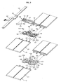
- FIG. 4 is an enlarged perspective view illustrating a first battery cell and a first flexible board shown in FIG. 3
- FIG. 5 is an enlarged perspective view illustrating a second battery cell and a second flexible board shown in FIG. 3
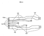
- FIG. 6 is an enlarged perspective view illustrating a third flexible board in the battery pack shown in FIG. 1 .
- the battery pack 100 includes a plurality of first battery cells 110, a first flexible board 120, a plurality of second battery cells 130, a second flexible board 140, a third flexible board 150, a circuit module 160, a frame 170, an insulation member 180, and a cover plate 190.
- the plurality of first battery cells 110 performs a discharging operation to supply power to an external load and a charging operation to receive power from a charging device.
- Each of the first battery cells 110 includes an electrode assembly (not shown) including a positive electrode, a negative electrode and a separator interposed between the positive and negative electrodes; a sheath 111 accommodating the electrode assembly and an electrolyte (not shown); and electrode tabs 112 and 113 electrically connected to the electrode assembly and extending to be exposed to the outside of the sheath 111.
- the sheath 111 may be a pouch case, and the first battery cells 110 accommodated by the pouch case can be easily processed into a desired shape. Thus, the first battery cells 110 may be easily applied to an external electronic device such as an external load.
- first battery cells 110 are coupled to each other in parallel and the corresponding electrode tabs 112 and 113 are disposed in pairs toward a central region located between the pairs of the electrode tabs 112 and 113 facing each other for connection to the first flexible board 120.
- the first flexible board 120 is disposed in the central region between the pairs of the electrode tabs 112 and 113 facing each other, to then be connected to the electrode tabs 112 and 113 of each of the plurality of first battery cells 110.
- the first flexible board 120 is electrically connected to each of the first battery cells 110, and electrically connects the first battery cells 110 to each other.
- the first flexible board 120 includes an insulation layer 121, a plurality of first welding terminal portions 122, positive temperature coefficient (PTC) terminal portions 123, PTC elements 124, a protruding surface portion in the form of a ridge 125, and second welding terminal portions 126.
- PTC positive temperature coefficient
- the insulation layer 121 is substantially planar shaped and has a first surface 121 a and a second surface 121b opposite to the first surface 121 a, forming an external appearance of the first flexible board 120.
- the insulation layer 121 is made of a flexible, insulating material, for example, polyimide.
- Cell connecting wires (not shown) for electrically connecting the plurality of first battery cells 110 to each other are formed within the insulation layer 121.
- the cell connecting wires and board connecting wires (not shown) may be made of a conductive material, for example, nickel.
- the plurality of first welding terminal portions 122 are formed such that ends of the cell connecting wires are exposed to the outside of the insulation layer 121, for example, to the first surface 121a and the second surface 121b.
- the plurality of first welding terminal portions 122 are electrically mechanically connected to the electrode tabs 112 and 113 of each of the plurality of first battery cells 110 by welding.
- the PTC terminal portions 123 are electrically connected to the cell connecting wires and the board connecting wires and are exposed to the outside of the insulation layer 121, for example, to the first surface 121a.
- the PTC terminal portions 123 are electrically mechanically connected to the PTC elements 124 by welding.
- the PTC elements 124 When an abnormal state, such as a high temperature state, occurs to the plurality of first battery cells 110 due to, for example, overcharge, the PTC elements 124 detect the abnormal state and shut down the circuit.
- the PTC elements 124 are provided in a one-to-one correspondence with respect to the first battery cells 110, and each of the PTC elements 124 is connected to a respective one of the first battery cells 110.
- the PTC elements 124 vary resistance values according to the temperature of the first battery cells 110, thereby controlling the current of the first battery cells 110.
- the ridge 125 protrudes from substantially the center of the insulation layer 121.
- the ridge 125 protrudes toward an upper portion of the insulation layer 121 and has a height equal to or greater than a thickness of each of the first battery cells 110.
- the ridge 125 protrudes high enough to contact the second flexible board 140 coupled to the upper portion of the first flexible board 120.
- the first flexible board 120 includes an alignment hole 120a formed at a region of the insulation layer 121.
- the alignment hole 120a is formed for the purpose of aligning stacking positions at which the first flexible board 120 is to be connected with the second flexible board 140.
- a separate pin (not shown) is positioned between the alignment hole 120a and the second flexible board 140 to achieve welding between the first flexible board 120 and the second flexible board 140 after alignment of the stacking positions.
- the second welding terminal portion 126 is formed on a top surface of the ridge 125.
- the second welding terminal portion 126 is electrically mechanically connected to the second flexible board 140 coupled to the upper portion of the first flexible board 120 by welding.
- the second welding terminal portion 126 electrically connects the second flexible board 140 to the electrode tabs 112 and 113 of each of the first battery cells 110 connected to the first flexible board 120. Therefore, the first battery cells 110 may operate with the same electrical signals as those of the second battery cells 130 connected to the second flexible board 140.
- the second battery cells 130 are positioned over the first battery cells 110. i.e. the second battery cells 130 are stacked on the first battery cells 110.
- the second battery cells 130 are connected to the second flexible board 140 in the same manner as the first battery cells 110 are connected to the first flexible board 120. i.e., the second battery cells 130 are surrounded by a sheath 131, and the electrode terminals 132 and 133 protruding outwardly from the sheath 131 are connected to the second flexible board 140 by, for example, welding.
- the second battery cells 130 are connected to the circuit module 160 through the second flexible board 140 and the third flexible board 150, thereby allowing electrical signals to be input/output.
- the second battery cells 130 may receive the same electrical signals as those of the first battery cells 110.
- the second flexible board 140 has a configuration similar to that of the first flexible board 120.
- the second flexible board 140 includes an insulation layer 141, a plurality of first welding terminal portions 142, positive temperature coefficient (PTC) terminal portions 143, PTC elements 144, second welding terminal portions 145, and soldering terminal portions 146.
- PTC positive temperature coefficient
- the insulation layer 141 is formed in the same manner as the insulation layer 121 of the first flexible board 120 and is shaped corresponding to the insulation layer 121.
- the insulation layer 141 has a first surface 141a and a second surface 141b opposite to the first surface 141 a, forming an external appearance of the second flexible board 140.
- the plurality of first welding terminal portions 142 are electrically mechanically connected to the electrode tabs 132 and 133 of each of the plurality of second battery cells 130 by welding.
- the PTC terminal portions 143 are exposed to the outside of the insulation layer 141, for example, to the first surface 141a of the insulation layer 141.
- the PTC elements 144 are the same as the PTC elements 120 of the first flexible board 120 and may be electrically mechanically connected to the PTC terminal portions 143 by, for example, soldering.
- the second welding terminal portions 145 are formed on a portion of a top surface of the insulation layer 141.
- the second welding terminal portions 145 are located in correspondence with the positions of the second welding terminal portions 126 of the first flexible board 120.
- the second welding terminal portions 145 of the second flexible board 140 and the second welding terminal portions 126 of the first flexible board 120 are connected with each other by welding. As a result, the first flexible board 120 and the second flexible board 140 may be electrically coupled to each other through the second welding terminal portions 145.
- the second flexible board 140 includes an alignment hole 140a formed at a region of the insulation layer 141.
- the alignment hole 140a is located in correspondence with the alignment hole 120a of the first flexible board 120. Therefore, as described above, after the first flexible board 120 and the second flexible board 140 are connected with each other using a separate pin (not shown), the second welding terminal portions 126 of the first flexible board 120 and the second welding terminal portions 145 of the second flexible board 140 may be welded.
- soldering terminal portions 146 are exposed to the outside of the insulation layer 141, for example, to the first surface 141a, and are electrically mechanically connected to first soldering terminal portions 153 of the third flexible board 150 by soldering.
- soldering is usually employed when the first soldering terminal portions 146 of the second flexible board 140 and first soldering terminal portions 153 of the third flexible board 150 are made of different materials.
- the third flexible board 150 is disposed over the second flexible board 140 and electrically connects the second flexible board 140 and the circuit module 160.
- the third flexible board 150 includes an insulation layer 151, a plurality of connection wires 152, a plurality of first soldering terminal portions 153 and a plurality of second soldering terminal portions 154.
- the insulation layer 151 is substantially planar shaped and has a first surface 151a, a second surface 151 b opposite to the first surface 151a, and a third surface 151c connecting the first surface 151 a and the second surface 151 b, forming an external appearance of the third flexible board 150.
- the insulation layer 151 includes a plurality of connection wires 152 inside and is formed such that a plurality of first soldering terminal portions 153 and second soldering terminal portions 154 are exposed outwardly.
- the insulation layer 151 has an open portion OP formed between each of the plurality of first soldering terminal portions 153.
- the insulation layer 151 has a bending portion BP formed in the vicinity of the circuit module 160.
- the bending portion BP forms a level difference.
- the insulation layer 151 is made of a flexible, insulating material, for example, polyimide.
- the plurality of connection wires 152 are patterns for electrically connecting the second flexible board 140 and the circuit module 160 to each other and are formed within the insulation layer 151.
- the plurality of connection wires 152 may include wires for detecting power of the second battery cells 130 and wires for detecting voltages of the first battery cells 130.
- the plurality of connection wires 152 may be made of a conductive material, for example, copper.
- the plurality of first soldering terminal portions 153 extend horizontally from one side ends of the plurality of connection wires 152 and are formed to be exposed to the outside of the insulation layer 151, for example, to the outside of the third surface 151 c.
- the plurality of first soldering terminal portions 153 are disposed corresponding to the soldering terminal portions 146 of the second flexible board 140 and may be electrically mechanically connected by, for example, soldering.
- the plurality of first soldering terminal portions 153 are integrally formed with the plurality of connection wires 152 and may be made of the same material as the plurality of connection wires 152.
- the plurality of second soldering terminal portions 154 extend horizontally from the other side ends of the plurality of connection wires 152 and are formed to be exposed to the outside of the insulation layer 151, for example, to the outside of the third surface 151 c.
- the plurality of second soldering terminal portions 154 are electrically mechanically connected to a plurality of conductive pads 161 of the circuit module 160 by soldering.
- the plurality of second soldering terminal portions 154 are substantially rectangular shaped with grooves 154a, and the grooves 154a provide for a space to be filled with lead when soldering the plurality of second soldering terminal portions 154 and the plurality of conductive pads 161, thereby enhancing electrical mechanical coupling forces between the plurality of second soldering terminal portions 154 and the plurality of conductive pads 161.
- the circuit module 160 includes the plurality of conductive pads 161 and is electrically mechanically connected to the third flexible board 150 when the plurality of second soldering terminal portions 154 of the third flexible board 150 contact the plurality of conductive pads 161 of the circuit module 160.
- the circuit module 160 is electrically connected to the plurality of battery cells 110 and 130 through the first flexible board 120, the second flexible board 140 and the third flexible board 150.
- the circuit module 160 includes on an insulating board a circuit capable of charging and discharging the plurality of battery cells 110 and 130 and a protection circuit for preventing overcharge or overdischarge of the plurality of battery cells 110 and 130.
- the circuit module 160 includes a connecting portion 162 for electrical connection to an external electronic device such as an external load or a charging device.
- the insulating board forming the circuit module 160 may be a rigid board.
- the frame 170 is formed to receive the plurality of battery cells 110 and 130, the first flexible board 120, the second flexible board 140, the third flexible board 150, and the circuit module 160, and may include fastening protrusions 171 formed at its external side.
- the frame 170 is made of an insulating material.
- the insulation member 180 includes a first insulation sheet 182 and a second insulation sheet 184 attached to top and bottom of the plurality of battery cells 110 and 130, respectively.
- the insulation member 160 prevents unnecessary shorts between the plurality of battery cells 110 and 130 and the cover plate 190.
- the cover plate 190 is formed to surround the plurality of battery cells 110 and 130, the first flexible board 120, the second flexible board 140, the third flexible board 150, the circuit module 160, the frame 170, and the insulation member 180, forming an external appearance of the battery pack 100.
- the cover plate 190 is made of a metallic material and reinforces the strength of sheaths 111 and 131 that are weaker in protecting the plurality of battery cells 110 and 130 against external forces.
- the cover plate 190 includes a first cover plate 192 and a second cover plate 194 disposed on and beneath the plurality of battery cells 110 and 130, respectively.
- the first cover plate 192 has a first fastening hole 192a
- the second cover plate 194 has a second fastening hole 194a.
- the first fastening hole 192a and the second fastening hole 194a are engaged with the fastening protrusions 171, thereby connecting the frame 170 with the cover plate 190.
- the first cover plate 192 has a first connector exposing groove 192b
- the second cover plate 194 has a second connector exposing groove 194b.
- the first connector exposing groove 192b and the second connector exposing groove 194b form a connector exposing hole 195 of the cover plate 190.
- the connecting portion 162 of the circuit module 160 is exposed to the outside of the cover plate 190 through the connector exposing hole 195.
- the electrode tabs 112 and 113 of the first battery cells 110 are connected to the first flexible board 120
- the electrode tabs 132 and 133 of the second battery cells 130 are connected to the second flexible board 140
- the second welding terminal portions 126 formed on the ridge 125 of the first flexible board 120 are welded to the second welding terminal portions 145 of the second flexible board 140, thereby easily connecting the battery cells 110 and 130 to each other when the battery cells 110 and 130 are stacked in multiple layers.
- the PTC elements 124 and 144 are formed in the first flexible board 120 and the second flexible board 140, they may be formed in the vicinity of the battery cells 110 and 130 and are stably coupled to the PTC elements 124 and 144.
Description
- An aspect of the present invention relates to a battery pack.
- In general, secondary batteries can be repeatedly charged and discharged, and are widely used in various fields, including mobile phones, notebook computers, Tablet PCs, cameras, camcorders, hybrid electric vehicles, electric vehicles, electric scooters, and so on. High power batteries that use a plurality of battery cells connected to each other in a battery pack are used as power sources for applications requiring high power. The plurality of battery cells are generally electrically connected to each other by a connection member such as wires or a nickel plate.
- One or more embodiments of the present invention seek to provide a battery pack, in which battery cells can be easily combined together while enabling a reduction in the manufacturing cost.
- According to a first aspect of the invention there is provided a battery pack comprising: at least one first battery cell electrically connected to a first flexible board; at least one second battery cell electrically connected to a second flexible board, the second flexible board being electrically connected to the first flexible board; and a circuit module electrically connected to the first flexible board and the second flexible board, and including a connection portion for electrically connecting the first and second flexible boards to an external device. The first flexible board is provided with a protruding surface portion protruding towards the second flexible board and a connection portion is provided on the protruding surface portion for electrical connecting, in the direction of stacking, to a corresponding connection portion of the second flexible board.
- In one or more embodiments the at least one first battery cell is arranged in a first layer; the at least one second battery cell is arranged in a second layer stacked over the first layer; and the second flexible board is stacked over the first flexible circuit board.
- For example, the first flexible board includes a ridge formed on one surface, and a welding terminal portion formed in the ridge, and the second flexible board includes a welding terminal portion located in correspondence with the welding terminal portion of the first flexible board, thereby enabling the welding terminal portions of the first flexible board and the second flexible board to be connected.
- In an embodiment, the height of the protruding surface portion corresponds to the thickness of the first battery cell.
- In an embodiment, the first flexible board is provided with at least one positive temperature coefficient element for protecting the at least one battery cell; and/or the second flexible board is provided with at least one positive temperature coefficient element for protecting the at least second battery cell. In an embodiment, at least one positive temperature coefficient (PTC) element may be formed on each top surface of the first flexible board and the second flexible board.
- In an embodiment, a positive temperature coefficient element is provided for a respective battery cell in a one to one correspondence.
- In an embodiment, a third board is provided to electrically connect the second flexible board to the circuit module.
- In an embodiment, the third board is arranged over the second flexible board.
- In an embodiment, the third board comprises a bending portion to compensate for a level difference between the circuit module and the second flexible board.
- In an embodiment, the battery pack comprises a plurality of first battery cells electrically connected to one another by the first flexible board and a plurality of second battery cells electrically connected to one another by the second flexible board.
- In an embodiment, a metallic cover plate is provided for enclosing the at least one first battery cell, the at least one second battery cell, the first flexible board, the second flexible board, the third flexible board and the circuit module, the metallic cover plate being provided with an aperture through which the connection portion of the circuit module extends.
- In an embodiment, the third board is flexible. In an embodiment, the at least one first battery cell includes electrodes electrically connected to the first flexible board by a weld connection and being absent of a bend and the at least one second battery cell includes electrodes electrically connected to the second flexible board by a weld connection and being absent of a bend.
- A related aspect of the invention provides a battery pack including first battery cells, a first flexible board connected to electrode tabs of the first battery cells, second battery cells stacked over the first battery cells, a second flexible board connected to electrode tabs of the second battery cells and connected in the direction of stacking to the first flexible board, a third flexible board having one end connected to the second flexible board, and a protection circuit module connected to the other end of the third flexible board.
- In the battery pack according to an embodiment of the present invention, electrode tabs of the first battery cell are connected to the first flexible board and electrode tabs of the second battery cells are connected to the second flexible board, and second welding terminal portions formed on the ridge of the first flexible board are welded to welding terminal portions of the second flexible board, thereby facilitating connection of the first and second battery cells to each other when the first and second battery cells are stacked in a plurality of layers.
- In addition, since PTC elements are formed on the first flexible board and the second flexible board, the PTC elements may be formed in the vicinity of the battery cells and may be stably combined with the battery cells.
- Further, since it is not necessary to bend electrode tabs when the battery cells are connected to each other, the PTC elements can be prevented from being separated from the battery cells.
-
-
FIG. 1 is an assembled perspective view of a battery pack according to an embodiment of the present invention; -
FIG. 2 is an exploded perspective view of the battery pack shown inFIG. 1 ; -
FIG. 3 is an exploded perspective view of the battery pack shown inFIG. 1 , from which a case is removed; -
FIG. 4 is an enlarged perspective view illustrating a first battery cell and a first flexible board shown inFIG. 3 ; -
FIG. 5 is an enlarged perspective view illustrating a second battery cell and a second flexible board shown inFIG. 3 ; and -
FIG. 6 is an enlarged perspective view illustrating a third flexible board in the battery pack shown inFIG. 1 . - An embodiment will now be described more fully hereinafter with reference to the accompanying drawings. It will be appreciated however, that the invention may be embodied in different forms and should not be construed as limited to the embodiments set forth herein. Rather, the embodiment is provided so that this disclosure will be thorough and complete, and will fully convey the scope of the invention to those skilled in the art.
- Hereinafter, a configuration of a battery pack according to the embodiment will be described.
-
FIG. 1 is an assembled perspective view of a battery pack according to an embodiment of the present invention,FIG. 2 is an exploded perspective view of the battery pack shown inFIG. 1 ,FIG. 3 is an exploded perspective view of the battery pack shown inFIG. 1 , from which a case is removed,FIG. 4 is an enlarged perspective view illustrating a first battery cell and a first flexible board shown inFIG. 3 ,FIG. 5 is an enlarged perspective view illustrating a second battery cell and a second flexible board shown inFIG. 3 , andFIG. 6 is an enlarged perspective view illustrating a third flexible board in the battery pack shown inFIG. 1 . - Referring to
FIGS. 1 to 6 , thebattery pack 100 according to the embodiment of the present invention includes a plurality offirst battery cells 110, a firstflexible board 120, a plurality ofsecond battery cells 130, a secondflexible board 140, a thirdflexible board 150, acircuit module 160, aframe 170, aninsulation member 180, and acover plate 190. - The plurality of
first battery cells 110 performs a discharging operation to supply power to an external load and a charging operation to receive power from a charging device. Each of thefirst battery cells 110 includes an electrode assembly (not shown) including a positive electrode, a negative electrode and a separator interposed between the positive and negative electrodes; asheath 111 accommodating the electrode assembly and an electrolyte (not shown); andelectrode tabs sheath 111. Thesheath 111 may be a pouch case, and thefirst battery cells 110 accommodated by the pouch case can be easily processed into a desired shape. Thus, thefirst battery cells 110 may be easily applied to an external electronic device such as an external load. - While the illustrated embodiment of the present invention includes a plurality of 4 first battery cells, it will be appreciated that the number of battery cells may be varied according to the output power level desired. A pair of the
first battery cells 110 are coupled to each other in parallel and thecorresponding electrode tabs electrode tabs flexible board 120. - The first
flexible board 120 is disposed in the central region between the pairs of theelectrode tabs electrode tabs first battery cells 110. The firstflexible board 120 is electrically connected to each of thefirst battery cells 110, and electrically connects thefirst battery cells 110 to each other. - The first
flexible board 120 includes aninsulation layer 121, a plurality of first weldingterminal portions 122, positive temperature coefficient (PTC)terminal portions 123,PTC elements 124, a protruding surface portion in the form of aridge 125, and second weldingterminal portions 126. - The
insulation layer 121 is substantially planar shaped and has afirst surface 121 a and asecond surface 121b opposite to thefirst surface 121 a, forming an external appearance of the firstflexible board 120. Theinsulation layer 121 is made of a flexible, insulating material, for example, polyimide. Cell connecting wires (not shown) for electrically connecting the plurality offirst battery cells 110 to each other are formed within theinsulation layer 121. The cell connecting wires and board connecting wires (not shown) may be made of a conductive material, for example, nickel. - The plurality of first welding
terminal portions 122 are formed such that ends of the cell connecting wires are exposed to the outside of theinsulation layer 121, for example, to thefirst surface 121a and thesecond surface 121b. The plurality of first weldingterminal portions 122 are electrically mechanically connected to theelectrode tabs first battery cells 110 by welding. - The
PTC terminal portions 123 are electrically connected to the cell connecting wires and the board connecting wires and are exposed to the outside of theinsulation layer 121, for example, to thefirst surface 121a. ThePTC terminal portions 123 are electrically mechanically connected to thePTC elements 124 by welding. - When an abnormal state, such as a high temperature state, occurs to the plurality of
first battery cells 110 due to, for example, overcharge, thePTC elements 124 detect the abnormal state and shut down the circuit. ThePTC elements 124 are provided in a one-to-one correspondence with respect to thefirst battery cells 110, and each of thePTC elements 124 is connected to a respective one of thefirst battery cells 110. ThePTC elements 124 vary resistance values according to the temperature of thefirst battery cells 110, thereby controlling the current of thefirst battery cells 110. - The
ridge 125 protrudes from substantially the center of theinsulation layer 121. Theridge 125 protrudes toward an upper portion of theinsulation layer 121 and has a height equal to or greater than a thickness of each of thefirst battery cells 110. Theridge 125 protrudes high enough to contact the secondflexible board 140 coupled to the upper portion of the firstflexible board 120. In addition, the firstflexible board 120 includes analignment hole 120a formed at a region of theinsulation layer 121. Thealignment hole 120a is formed for the purpose of aligning stacking positions at which the firstflexible board 120 is to be connected with the secondflexible board 140. A separate pin (not shown) is positioned between thealignment hole 120a and the secondflexible board 140 to achieve welding between the firstflexible board 120 and the secondflexible board 140 after alignment of the stacking positions. - The second
welding terminal portion 126 is formed on a top surface of theridge 125. The secondwelding terminal portion 126 is electrically mechanically connected to the secondflexible board 140 coupled to the upper portion of the firstflexible board 120 by welding. The secondwelding terminal portion 126 electrically connects the secondflexible board 140 to theelectrode tabs first battery cells 110 connected to the firstflexible board 120. Therefore, thefirst battery cells 110 may operate with the same electrical signals as those of thesecond battery cells 130 connected to the secondflexible board 140. - The
second battery cells 130 are positioned over thefirst battery cells 110. i.e. thesecond battery cells 130 are stacked on thefirst battery cells 110. In addition, thesecond battery cells 130 are connected to the secondflexible board 140 in the same manner as thefirst battery cells 110 are connected to the firstflexible board 120. i.e., thesecond battery cells 130 are surrounded by asheath 131, and theelectrode terminals sheath 131 are connected to the secondflexible board 140 by, for example, welding. Thesecond battery cells 130 are connected to thecircuit module 160 through the secondflexible board 140 and the thirdflexible board 150, thereby allowing electrical signals to be input/output. In addition, as described above, since the firstflexible board 120 and the secondflexible board 140 are electrically connected, thesecond battery cells 130 may receive the same electrical signals as those of thefirst battery cells 110. - The second
flexible board 140 has a configuration similar to that of the firstflexible board 120. The secondflexible board 140 includes aninsulation layer 141, a plurality of firstwelding terminal portions 142, positive temperature coefficient (PTC)terminal portions 143,PTC elements 144, secondwelding terminal portions 145, and solderingterminal portions 146. - The
insulation layer 141 is formed in the same manner as theinsulation layer 121 of the firstflexible board 120 and is shaped corresponding to theinsulation layer 121. - The
insulation layer 141 has afirst surface 141a and asecond surface 141b opposite to thefirst surface 141 a, forming an external appearance of the secondflexible board 140. - The plurality of first
welding terminal portions 142 are electrically mechanically connected to theelectrode tabs second battery cells 130 by welding. - The
PTC terminal portions 143 are exposed to the outside of theinsulation layer 141, for example, to thefirst surface 141a of theinsulation layer 141. ThePTC elements 144 are the same as thePTC elements 120 of the firstflexible board 120 and may be electrically mechanically connected to thePTC terminal portions 143 by, for example, soldering. - The second
welding terminal portions 145 are formed on a portion of a top surface of theinsulation layer 141. The secondwelding terminal portions 145 are located in correspondence with the positions of the secondwelding terminal portions 126 of the firstflexible board 120. The secondwelding terminal portions 145 of the secondflexible board 140 and the secondwelding terminal portions 126 of the firstflexible board 120 are connected with each other by welding. As a result, the firstflexible board 120 and the secondflexible board 140 may be electrically coupled to each other through the secondwelding terminal portions 145. - In addition, the second
flexible board 140 includes analignment hole 140a formed at a region of theinsulation layer 141. Thealignment hole 140a is located in correspondence with thealignment hole 120a of the firstflexible board 120. Therefore, as described above, after the firstflexible board 120 and the secondflexible board 140 are connected with each other using a separate pin (not shown), the secondwelding terminal portions 126 of the firstflexible board 120 and the secondwelding terminal portions 145 of the secondflexible board 140 may be welded. - The soldering
terminal portions 146 are exposed to the outside of theinsulation layer 141, for example, to thefirst surface 141a, and are electrically mechanically connected to firstsoldering terminal portions 153 of the thirdflexible board 150 by soldering. Here, the soldering is usually employed when the firstsoldering terminal portions 146 of the secondflexible board 140 and firstsoldering terminal portions 153 of the thirdflexible board 150 are made of different materials. - The third
flexible board 150 is disposed over the secondflexible board 140 and electrically connects the secondflexible board 140 and thecircuit module 160. Specifically, the thirdflexible board 150 includes aninsulation layer 151, a plurality ofconnection wires 152, a plurality of firstsoldering terminal portions 153 and a plurality of secondsoldering terminal portions 154. - The
insulation layer 151 is substantially planar shaped and has afirst surface 151a, asecond surface 151 b opposite to thefirst surface 151a, and athird surface 151c connecting thefirst surface 151 a and thesecond surface 151 b, forming an external appearance of the thirdflexible board 150. Theinsulation layer 151 includes a plurality ofconnection wires 152 inside and is formed such that a plurality of firstsoldering terminal portions 153 and secondsoldering terminal portions 154 are exposed outwardly. In addition, theinsulation layer 151 has an open portion OP formed between each of the plurality of firstsoldering terminal portions 153. Further, theinsulation layer 151 has a bending portion BP formed in the vicinity of thecircuit module 160. The bending portion BP forms a level difference. When there is a height difference between thecircuit module 160 and the secondflexible board 140, the bending portion BP allows thecircuit module 160 and the firstflexible board 140 to be connected to each other in a stable manner. Here, theinsulation layer 151 is made of a flexible, insulating material, for example, polyimide. - The plurality of
connection wires 152 are patterns for electrically connecting the secondflexible board 140 and thecircuit module 160 to each other and are formed within theinsulation layer 151. The plurality ofconnection wires 152 may include wires for detecting power of thesecond battery cells 130 and wires for detecting voltages of thefirst battery cells 130. The plurality ofconnection wires 152 may be made of a conductive material, for example, copper. - The plurality of first
soldering terminal portions 153 extend horizontally from one side ends of the plurality ofconnection wires 152 and are formed to be exposed to the outside of theinsulation layer 151, for example, to the outside of thethird surface 151 c. The plurality of firstsoldering terminal portions 153 are disposed corresponding to the solderingterminal portions 146 of the secondflexible board 140 and may be electrically mechanically connected by, for example, soldering. The plurality of firstsoldering terminal portions 153 are integrally formed with the plurality ofconnection wires 152 and may be made of the same material as the plurality ofconnection wires 152. - The plurality of second
soldering terminal portions 154 extend horizontally from the other side ends of the plurality ofconnection wires 152 and are formed to be exposed to the outside of theinsulation layer 151, for example, to the outside of thethird surface 151 c. The plurality of secondsoldering terminal portions 154 are electrically mechanically connected to a plurality ofconductive pads 161 of thecircuit module 160 by soldering. The plurality of secondsoldering terminal portions 154 are substantially rectangular shaped withgrooves 154a, and thegrooves 154a provide for a space to be filled with lead when soldering the plurality of secondsoldering terminal portions 154 and the plurality ofconductive pads 161, thereby enhancing electrical mechanical coupling forces between the plurality of secondsoldering terminal portions 154 and the plurality ofconductive pads 161. - The
circuit module 160 includes the plurality ofconductive pads 161 and is electrically mechanically connected to the thirdflexible board 150 when the plurality of secondsoldering terminal portions 154 of the thirdflexible board 150 contact the plurality ofconductive pads 161 of thecircuit module 160. Thecircuit module 160 is electrically connected to the plurality ofbattery cells flexible board 120, the secondflexible board 140 and the thirdflexible board 150. Although not shown, thecircuit module 160 includes on an insulating board a circuit capable of charging and discharging the plurality ofbattery cells battery cells circuit module 160 includes a connectingportion 162 for electrical connection to an external electronic device such as an external load or a charging device. The insulating board forming thecircuit module 160 may be a rigid board. - The
frame 170 is formed to receive the plurality ofbattery cells flexible board 120, the secondflexible board 140, the thirdflexible board 150, and thecircuit module 160, and may includefastening protrusions 171 formed at its external side. Theframe 170 is made of an insulating material. - The
insulation member 180 includes afirst insulation sheet 182 and asecond insulation sheet 184 attached to top and bottom of the plurality ofbattery cells insulation member 160 prevents unnecessary shorts between the plurality ofbattery cells cover plate 190. - The
cover plate 190 is formed to surround the plurality ofbattery cells flexible board 120, the secondflexible board 140, the thirdflexible board 150, thecircuit module 160, theframe 170, and theinsulation member 180, forming an external appearance of thebattery pack 100. In addition, thecover plate 190 is made of a metallic material and reinforces the strength ofsheaths battery cells cover plate 190 includes afirst cover plate 192 and asecond cover plate 194 disposed on and beneath the plurality ofbattery cells first cover plate 192 has afirst fastening hole 192a, and thesecond cover plate 194 has asecond fastening hole 194a. Thefirst fastening hole 192a and thesecond fastening hole 194a are engaged with thefastening protrusions 171, thereby connecting theframe 170 with thecover plate 190. In addition, thefirst cover plate 192 has a firstconnector exposing groove 192b, and thesecond cover plate 194 has a secondconnector exposing groove 194b. The firstconnector exposing groove 192b and the secondconnector exposing groove 194b form aconnector exposing hole 195 of thecover plate 190. The connectingportion 162 of thecircuit module 160 is exposed to the outside of thecover plate 190 through theconnector exposing hole 195. - As described above, in the
battery pack 100 according to the embodiment of the present invention, theelectrode tabs first battery cells 110 are connected to the firstflexible board 120, theelectrode tabs second battery cells 130 are connected to the secondflexible board 140, and the secondwelding terminal portions 126 formed on theridge 125 of the firstflexible board 120 are welded to the secondwelding terminal portions 145 of the secondflexible board 140, thereby easily connecting thebattery cells battery cells - In addition, since the
PTC elements flexible board 120 and the secondflexible board 140, they may be formed in the vicinity of thebattery cells PTC elements - Further, it is not necessary to bend the
electrode tabs first battery cells 110 and theelectrode tabs second battery cells 130 when combining the first andsecond battery cells PTC elements second battery cells - An exemplary embodiment of a battery pack has been disclosed herein, and although specific terms are employed, they are used and are to be interpreted in a generic and descriptive sense only and not for purpose of limitation. Accordingly, it will be understood by those of ordinary skill in the art that various changes in form and details may be made without departing from the scope of the present invention as set forth in the following claims.
Claims (12)
- A battery pack (100) comprising:at least one first battery cell (110) electrically connected to a first flexible board (120);at least one second battery cell (130) electrically connected to a second flexible board (140), the second flexible board (140) being electrically connected to the first flexible board (120); anda circuit module (160) electrically connected to the first flexible board (120) and the second flexible board (140), and including a connection portion for electrically connecting the first and second flexible boards to an external device, characterized in thatthe first flexible board (120) is provided with a protruding surface portion (125) protruding towards the second flexible board (140) and a connection portion (126) is provided on the protruding surface portion (125) for electrical connecting, in the direction of stacking, to a corresponding connection portion of the second flexible board (120).
- A battery pack according to claim 1 wherein
the at least one first battery cell (110) is arranged in a first layer;
the at least one second battery cell (130) is arranged in a second layer stacked over the first layer; and
the second flexible board (140) is stacked over the first flexible board (120). - A battery pack according to claim 2 wherein the height of the protruding surface portion (125) corresponds to the thickness of the first battery cell (110).
- A battery pack according to any preceding claim wherein the first flexible board (120) is provided with at least one positive temperature coefficient element (123) for protecting the at least one first battery cell (110); and/or the second flexible board (140) is provided with at least one positive temperature coefficient element (143) for protecting the at least one second battery cell.
- A battery pack according to claim 4 wherein a positive temperature coefficient element (123; 143) is provided for a respective battery cell in a one to one correspondence.
- A battery pack according to any preceding claim further comprising a third board (150) electrically connecting the second flexible board (140) to the circuit module (160).
- A battery pack according to claim 6, wherein the third board (150) is arranged over the second flexible board.
- A battery pack according to claim 6 or 7, wherein the third board (150) comprises a bending portion to compensate for a level difference between the circuit module (160) and the second flexible board (140).
- A battery pack according to any preceding claim comprising a plurality of first battery cells (110) electrically connected to one another by the first flexible board (120) and a plurality of second battery cells (130) electrically connected to one another by the second flexible board (140).
- A battery pack according to any one of claims 6 to 9 further comprising a metallic cover plate (190) for enclosing the at least one first battery cell (110), the at least one second battery cell (130), the first flexible board (120), the second flexible board (140), the third flexible board (150) and the circuit module (160), the metallic cover plate (190) being provided with an aperture (195) through which the connection portion of the circuit module (160) extends.
- A battery pack according to any one of claims 6 to 10 wherein the third board (150) is flexible
- A battery pack according to any preceding claim wherein the at least one first battery cell includes electrodes electrically connected to the first flexible board by a weld connection and being absent of a bend and the at least one second battery cell includes electrodes electrically connected to the second flexible board by a weld connection and being absent of a bend.
Applications Claiming Priority (2)
| Application Number | Priority Date | Filing Date | Title |
|---|---|---|---|
| US201161504936P | 2011-07-06 | 2011-07-06 | |
| US13/426,362 US9017836B2 (en) | 2011-07-06 | 2012-03-21 | Battery pack |
Publications (2)
| Publication Number | Publication Date |
|---|---|
| EP2544263A1 EP2544263A1 (en) | 2013-01-09 |
| EP2544263B1 true EP2544263B1 (en) | 2014-04-23 |
Family
ID=46458334
Family Applications (1)
| Application Number | Title | Priority Date | Filing Date |
|---|---|---|---|
| EP12175133.3A Not-in-force EP2544263B1 (en) | 2011-07-06 | 2012-07-05 | Battery pack |
Country Status (4)
| Country | Link |
|---|---|
| US (1) | US9017836B2 (en) |
| EP (1) | EP2544263B1 (en) |
| KR (1) | KR20130006279A (en) |
| CN (1) | CN102867981A (en) |
Families Citing this family (23)
| Publication number | Priority date | Publication date | Assignee | Title |
|---|---|---|---|---|
| KR102016753B1 (en) * | 2013-02-05 | 2019-10-21 | 삼성에스디아이 주식회사 | Battery pack |
| KR102016754B1 (en) * | 2013-02-05 | 2019-10-21 | 삼성에스디아이 주식회사 | Battery pack |
| KR102018693B1 (en) * | 2013-02-06 | 2019-09-05 | 삼성에스디아이 주식회사 | Rechargeable battery pack |
| KR102161628B1 (en) * | 2014-03-14 | 2020-10-05 | 삼성에스디아이 주식회사 | Protection circuit module for battery and battery pack comprising the same |
| US10826136B2 (en) | 2014-07-24 | 2020-11-03 | The Boeing Company | Battery pack including stacked battery-board assemblies |
| WO2016068551A1 (en) * | 2014-10-29 | 2016-05-06 | 주식회사 엘지화학 | Unit battery pack |
| KR102320437B1 (en) * | 2015-03-03 | 2021-11-01 | 삼성에스디아이 주식회사 | Flexible rechargeable battery |
| KR102266594B1 (en) * | 2015-03-13 | 2021-06-17 | 삼성에스디아이 주식회사 | Rechargeable battery |
| KR101723052B1 (en) * | 2015-12-23 | 2017-04-05 | 주식회사 유라코퍼레이션 | Coupling assembly of battery cell terminal and coupling structure for measuring battery of the same |
| KR102505611B1 (en) * | 2016-03-21 | 2023-03-03 | 삼성에스디아이 주식회사 | Battery pack |
| CN106231011B (en) * | 2016-07-28 | 2020-01-10 | Oppo广东移动通信有限公司 | Mobile terminal |
| KR102247395B1 (en) * | 2016-10-05 | 2021-05-03 | 삼성에스디아이 주식회사 | Rechargeable battery |
| US10847775B2 (en) * | 2016-10-14 | 2020-11-24 | Tiveni Mergeco, Inc. | Multi-layer contact plate configured to establish electrical bonds to battery cells in a battery module |
| KR102033001B1 (en) * | 2017-02-28 | 2019-10-16 | 주식회사 유라코퍼레이션 | Frame assembly, method of manufacturing frame assembly, and method of manufacturing battery module |
| US11038192B2 (en) | 2017-06-02 | 2021-06-15 | GM Global Technology Operations LLC | Configurations for power module having an integrated flexible circuit assembly |
| US10375830B2 (en) * | 2017-06-02 | 2019-08-06 | GM Global Technology Operations LLC | Method of assembling power module via folding |
| KR102409424B1 (en) * | 2017-08-29 | 2022-06-15 | 주식회사 엘지에너지솔루션 | Battery module, manufacturing method the same |
| US20190081364A1 (en) * | 2017-09-12 | 2019-03-14 | Sf Motors, Inc. | Integrated sense board of electric vehicle battery management system |
| KR102591517B1 (en) * | 2018-05-15 | 2023-10-19 | 삼성에스디아이 주식회사 | Battery pack |
| KR102562684B1 (en) * | 2018-05-15 | 2023-08-03 | 삼성에스디아이 주식회사 | Battery pack |
| US11431042B2 (en) * | 2019-09-10 | 2022-08-30 | Meta Platforms Technologies, Llc | Battery pack architecture for parallel connection of cells |
| KR20210137825A (en) * | 2020-05-11 | 2021-11-18 | 삼성에스디아이 주식회사 | Battery pack |
| KR20230115751A (en) * | 2022-01-27 | 2023-08-03 | 삼성에스디아이 주식회사 | Battery pack connector |
Family Cites Families (17)
| Publication number | Priority date | Publication date | Assignee | Title |
|---|---|---|---|---|
| FR2718886B1 (en) | 1994-04-13 | 1996-05-24 | Accumulateurs Fixes | Electrical connection system for electrochemical generator. |
| US7198866B2 (en) * | 2002-07-09 | 2007-04-03 | Nissan Motor Co., Ltd. | Cell assembly |
| KR100958647B1 (en) | 2002-12-18 | 2010-05-20 | 삼성에스디아이 주식회사 | Pouch type secondary battery |
| KR100516768B1 (en) | 2003-08-16 | 2005-09-22 | 삼성에스디아이 주식회사 | Secondary Battery having Parallel-Tap Combining Structure and Method of Combining the Tab |
| JP3882818B2 (en) | 2004-01-15 | 2007-02-21 | ソニー株式会社 | Battery pack |
| EP1737057B1 (en) | 2004-03-31 | 2011-09-14 | NEC Corporation | Process for producing a battery pack |
| US20050271934A1 (en) | 2004-06-05 | 2005-12-08 | Kiger William B | Battery pack assembly |
| KR100624977B1 (en) | 2004-09-22 | 2006-09-15 | 삼성에스디아이 주식회사 | Pouch Type Li Secondary Battery |
| PL1815486T3 (en) | 2004-11-22 | 2013-03-29 | Semikron Elektronik Gmbh & Co Kg | Connection system between capacitor batteries |
| WO2007032273A1 (en) | 2005-09-13 | 2007-03-22 | Nec Corporation | Electric device module and production method therefor |
| KR100895203B1 (en) | 2006-05-15 | 2009-05-06 | 주식회사 엘지화학 | Middle or Large-sized Battery Module |
| KR100959871B1 (en) * | 2007-12-17 | 2010-05-27 | 삼성에스디아이 주식회사 | Protection circuit board and battery pack using the same |
| US8999536B2 (en) | 2008-06-20 | 2015-04-07 | Samsung Sdi Co., Ltd. | Battery pack |
| KR100995429B1 (en) * | 2008-10-13 | 2010-11-18 | 삼성에스디아이 주식회사 | Battery pack |
| KR101016849B1 (en) | 2008-12-03 | 2011-02-22 | 삼성에스디아이 주식회사 | Secondary Battery |
| US8557411B2 (en) | 2009-08-14 | 2013-10-15 | Samsung Sdi Co., Ltd. | Secondary battery with a connection tab folded around an insulator and method of manufacturing the same |
| KR101621099B1 (en) * | 2009-12-18 | 2016-05-16 | 삼성에스디아이 주식회사 | Battery Pack and method for fabricating the same |
-
2012
- 2012-03-21 US US13/426,362 patent/US9017836B2/en not_active Expired - Fee Related
- 2012-04-30 KR KR1020120045806A patent/KR20130006279A/en not_active Application Discontinuation
- 2012-05-14 CN CN2012101494245A patent/CN102867981A/en active Pending
- 2012-07-05 EP EP12175133.3A patent/EP2544263B1/en not_active Not-in-force
Also Published As
| Publication number | Publication date |
|---|---|
| KR20130006279A (en) | 2013-01-16 |
| CN102867981A (en) | 2013-01-09 |
| US9017836B2 (en) | 2015-04-28 |
| EP2544263A1 (en) | 2013-01-09 |
| US20130011700A1 (en) | 2013-01-10 |
Similar Documents
| Publication | Publication Date | Title |
|---|---|---|
| EP2544263B1 (en) | Battery pack | |
| US9716258B2 (en) | Battery pack | |
| JP5394522B2 (en) | Separating type connecting member for manufacturing secondary battery module and method for improving battery module performance by voltage leveling | |
| EP1839349B1 (en) | Sensing board assembly for secondary battery module | |
| KR101127615B1 (en) | Battery pack | |
| US8435656B2 (en) | Secondary battery with protection circuit module | |
| US10601081B2 (en) | Battery pack | |
| KR100995444B1 (en) | Battery pack | |
| US8329326B2 (en) | Electrochemical device | |
| KR101230495B1 (en) | Battery Pack of High Capacity | |
| US20110129700A1 (en) | Battery pack | |
| US8440341B2 (en) | Battery pack | |
| US9240618B2 (en) | Rechargeable battery and battery module | |
| US20110008653A1 (en) | Polymer battery pack | |
| US20110008651A1 (en) | Battery pack | |
| US9099723B2 (en) | Battery pack and manufacturing method thereof | |
| US8492012B2 (en) | Secondary battery having discrete circuit modules | |
| US8679657B2 (en) | Battery pack | |
| US20140349141A1 (en) | Battery pack | |
| US9362543B2 (en) | Battery pack |
Legal Events
| Date | Code | Title | Description |
|---|---|---|---|
| PUAI | Public reference made under article 153(3) epc to a published international application that has entered the european phase |
Free format text: ORIGINAL CODE: 0009012 |
|
| AK | Designated contracting states |
Kind code of ref document: A1 Designated state(s): AL AT BE BG CH CY CZ DE DK EE ES FI FR GB GR HR HU IE IS IT LI LT LU LV MC MK MT NL NO PL PT RO RS SE SI SK SM TR |
|
| AX | Request for extension of the european patent |
Extension state: BA ME |
|
| 17P | Request for examination filed |
Effective date: 20130604 |
|
| RBV | Designated contracting states (corrected) |
Designated state(s): AL AT BE BG CH CY CZ DE DK EE ES FI FR GB GR HR HU IE IS IT LI LT LU LV MC MK MT NL NO PL PT RO RS SE SI SK SM TR |
|
| RIC1 | Information provided on ipc code assigned before grant |
Ipc: H01M 10/04 20060101ALI20130723BHEP Ipc: H01M 2/26 20060101ALI20130723BHEP Ipc: H01M 2/10 20060101ALI20130723BHEP Ipc: H01M 2/20 20060101AFI20130723BHEP |
|
| GRAP | Despatch of communication of intention to grant a patent |
Free format text: ORIGINAL CODE: EPIDOSNIGR1 |
|
| INTG | Intention to grant announced |
Effective date: 20131004 |
|
| GRAS | Grant fee paid |
Free format text: ORIGINAL CODE: EPIDOSNIGR3 |
|
| GRAA | (expected) grant |
Free format text: ORIGINAL CODE: 0009210 |
|
| AK | Designated contracting states |
Kind code of ref document: B1 Designated state(s): AL AT BE BG CH CY CZ DE DK EE ES FI FR GB GR HR HU IE IS IT LI LT LU LV MC MK MT NL NO PL PT RO RS SE SI SK SM TR |
|
| REG | Reference to a national code |
Ref country code: GB Ref legal event code: FG4D |
|
| REG | Reference to a national code |
Ref country code: CH Ref legal event code: EP |
|
| REG | Reference to a national code |
Ref country code: AT Ref legal event code: REF Ref document number: 664287 Country of ref document: AT Kind code of ref document: T Effective date: 20140515 |
|
| REG | Reference to a national code |
Ref country code: IE Ref legal event code: FG4D |
|
| REG | Reference to a national code |
Ref country code: DE Ref legal event code: R096 Ref document number: 602012001472 Country of ref document: DE Effective date: 20140612 |
|
| REG | Reference to a national code |
Ref country code: AT Ref legal event code: MK05 Ref document number: 664287 Country of ref document: AT Kind code of ref document: T Effective date: 20140423 |
|
| REG | Reference to a national code |
Ref country code: NL Ref legal event code: VDEP Effective date: 20140423 |
|
| REG | Reference to a national code |
Ref country code: LT Ref legal event code: MG4D |
|
| PG25 | Lapsed in a contracting state [announced via postgrant information from national office to epo] |
Ref country code: BG Free format text: LAPSE BECAUSE OF FAILURE TO SUBMIT A TRANSLATION OF THE DESCRIPTION OR TO PAY THE FEE WITHIN THE PRESCRIBED TIME-LIMIT Effective date: 20140723 Ref country code: LT Free format text: LAPSE BECAUSE OF FAILURE TO SUBMIT A TRANSLATION OF THE DESCRIPTION OR TO PAY THE FEE WITHIN THE PRESCRIBED TIME-LIMIT Effective date: 20140423 Ref country code: FI Free format text: LAPSE BECAUSE OF FAILURE TO SUBMIT A TRANSLATION OF THE DESCRIPTION OR TO PAY THE FEE WITHIN THE PRESCRIBED TIME-LIMIT Effective date: 20140423 Ref country code: NO Free format text: LAPSE BECAUSE OF FAILURE TO SUBMIT A TRANSLATION OF THE DESCRIPTION OR TO PAY THE FEE WITHIN THE PRESCRIBED TIME-LIMIT Effective date: 20140723 Ref country code: NL Free format text: LAPSE BECAUSE OF FAILURE TO SUBMIT A TRANSLATION OF THE DESCRIPTION OR TO PAY THE FEE WITHIN THE PRESCRIBED TIME-LIMIT Effective date: 20140423 Ref country code: GR Free format text: LAPSE BECAUSE OF FAILURE TO SUBMIT A TRANSLATION OF THE DESCRIPTION OR TO PAY THE FEE WITHIN THE PRESCRIBED TIME-LIMIT Effective date: 20140724 Ref country code: CY Free format text: LAPSE BECAUSE OF FAILURE TO SUBMIT A TRANSLATION OF THE DESCRIPTION OR TO PAY THE FEE WITHIN THE PRESCRIBED TIME-LIMIT Effective date: 20140423 Ref country code: IS Free format text: LAPSE BECAUSE OF FAILURE TO SUBMIT A TRANSLATION OF THE DESCRIPTION OR TO PAY THE FEE WITHIN THE PRESCRIBED TIME-LIMIT Effective date: 20140823 |
|
| PG25 | Lapsed in a contracting state [announced via postgrant information from national office to epo] |
Ref country code: SE Free format text: LAPSE BECAUSE OF FAILURE TO SUBMIT A TRANSLATION OF THE DESCRIPTION OR TO PAY THE FEE WITHIN THE PRESCRIBED TIME-LIMIT Effective date: 20140423 Ref country code: ES Free format text: LAPSE BECAUSE OF FAILURE TO SUBMIT A TRANSLATION OF THE DESCRIPTION OR TO PAY THE FEE WITHIN THE PRESCRIBED TIME-LIMIT Effective date: 20140423 Ref country code: PL Free format text: LAPSE BECAUSE OF FAILURE TO SUBMIT A TRANSLATION OF THE DESCRIPTION OR TO PAY THE FEE WITHIN THE PRESCRIBED TIME-LIMIT Effective date: 20140423 Ref country code: RS Free format text: LAPSE BECAUSE OF FAILURE TO SUBMIT A TRANSLATION OF THE DESCRIPTION OR TO PAY THE FEE WITHIN THE PRESCRIBED TIME-LIMIT Effective date: 20140423 Ref country code: AT Free format text: LAPSE BECAUSE OF FAILURE TO SUBMIT A TRANSLATION OF THE DESCRIPTION OR TO PAY THE FEE WITHIN THE PRESCRIBED TIME-LIMIT Effective date: 20140423 Ref country code: HR Free format text: LAPSE BECAUSE OF FAILURE TO SUBMIT A TRANSLATION OF THE DESCRIPTION OR TO PAY THE FEE WITHIN THE PRESCRIBED TIME-LIMIT Effective date: 20140423 Ref country code: LV Free format text: LAPSE BECAUSE OF FAILURE TO SUBMIT A TRANSLATION OF THE DESCRIPTION OR TO PAY THE FEE WITHIN THE PRESCRIBED TIME-LIMIT Effective date: 20140423 |
|
| PG25 | Lapsed in a contracting state [announced via postgrant information from national office to epo] |
Ref country code: PT Free format text: LAPSE BECAUSE OF FAILURE TO SUBMIT A TRANSLATION OF THE DESCRIPTION OR TO PAY THE FEE WITHIN THE PRESCRIBED TIME-LIMIT Effective date: 20140825 |
|
| REG | Reference to a national code |
Ref country code: DE Ref legal event code: R097 Ref document number: 602012001472 Country of ref document: DE |
|
| PG25 | Lapsed in a contracting state [announced via postgrant information from national office to epo] |
Ref country code: DK Free format text: LAPSE BECAUSE OF FAILURE TO SUBMIT A TRANSLATION OF THE DESCRIPTION OR TO PAY THE FEE WITHIN THE PRESCRIBED TIME-LIMIT Effective date: 20140423 Ref country code: SK Free format text: LAPSE BECAUSE OF FAILURE TO SUBMIT A TRANSLATION OF THE DESCRIPTION OR TO PAY THE FEE WITHIN THE PRESCRIBED TIME-LIMIT Effective date: 20140423 Ref country code: BE Free format text: LAPSE BECAUSE OF FAILURE TO SUBMIT A TRANSLATION OF THE DESCRIPTION OR TO PAY THE FEE WITHIN THE PRESCRIBED TIME-LIMIT Effective date: 20140423 Ref country code: CZ Free format text: LAPSE BECAUSE OF FAILURE TO SUBMIT A TRANSLATION OF THE DESCRIPTION OR TO PAY THE FEE WITHIN THE PRESCRIBED TIME-LIMIT Effective date: 20140423 Ref country code: RO Free format text: LAPSE BECAUSE OF FAILURE TO SUBMIT A TRANSLATION OF THE DESCRIPTION OR TO PAY THE FEE WITHIN THE PRESCRIBED TIME-LIMIT Effective date: 20140423 Ref country code: EE Free format text: LAPSE BECAUSE OF FAILURE TO SUBMIT A TRANSLATION OF THE DESCRIPTION OR TO PAY THE FEE WITHIN THE PRESCRIBED TIME-LIMIT Effective date: 20140423 |
|
| PG25 | Lapsed in a contracting state [announced via postgrant information from national office to epo] |
Ref country code: LU Free format text: LAPSE BECAUSE OF FAILURE TO SUBMIT A TRANSLATION OF THE DESCRIPTION OR TO PAY THE FEE WITHIN THE PRESCRIBED TIME-LIMIT Effective date: 20140705 |
|
| PLBE | No opposition filed within time limit |
Free format text: ORIGINAL CODE: 0009261 |
|
| STAA | Information on the status of an ep patent application or granted ep patent |
Free format text: STATUS: NO OPPOSITION FILED WITHIN TIME LIMIT |
|
| PG25 | Lapsed in a contracting state [announced via postgrant information from national office to epo] |
Ref country code: IT Free format text: LAPSE BECAUSE OF FAILURE TO SUBMIT A TRANSLATION OF THE DESCRIPTION OR TO PAY THE FEE WITHIN THE PRESCRIBED TIME-LIMIT Effective date: 20140423 |
|
| 26N | No opposition filed |
Effective date: 20150126 |
|
| REG | Reference to a national code |
Ref country code: IE Ref legal event code: MM4A |
|
| REG | Reference to a national code |
Ref country code: DE Ref legal event code: R097 Ref document number: 602012001472 Country of ref document: DE Effective date: 20150126 |
|
| REG | Reference to a national code |
Ref country code: FR Ref legal event code: PLFP Year of fee payment: 4 |
|
| PG25 | Lapsed in a contracting state [announced via postgrant information from national office to epo] |
Ref country code: SI Free format text: LAPSE BECAUSE OF FAILURE TO SUBMIT A TRANSLATION OF THE DESCRIPTION OR TO PAY THE FEE WITHIN THE PRESCRIBED TIME-LIMIT Effective date: 20140423 |
|
| PG25 | Lapsed in a contracting state [announced via postgrant information from national office to epo] |
Ref country code: IE Free format text: LAPSE BECAUSE OF NON-PAYMENT OF DUE FEES Effective date: 20140705 |
|
| PGFP | Annual fee paid to national office [announced via postgrant information from national office to epo] |
Ref country code: DE Payment date: 20150630 Year of fee payment: 4 |
|
| PGFP | Annual fee paid to national office [announced via postgrant information from national office to epo] |
Ref country code: FR Payment date: 20150629 Year of fee payment: 4 |
|
| REG | Reference to a national code |
Ref country code: CH Ref legal event code: PL |
|
| PG25 | Lapsed in a contracting state [announced via postgrant information from national office to epo] |
Ref country code: MC Free format text: LAPSE BECAUSE OF FAILURE TO SUBMIT A TRANSLATION OF THE DESCRIPTION OR TO PAY THE FEE WITHIN THE PRESCRIBED TIME-LIMIT Effective date: 20140423 Ref country code: CH Free format text: LAPSE BECAUSE OF NON-PAYMENT OF DUE FEES Effective date: 20150731 Ref country code: LI Free format text: LAPSE BECAUSE OF NON-PAYMENT OF DUE FEES Effective date: 20150731 Ref country code: SM Free format text: LAPSE BECAUSE OF FAILURE TO SUBMIT A TRANSLATION OF THE DESCRIPTION OR TO PAY THE FEE WITHIN THE PRESCRIBED TIME-LIMIT Effective date: 20140423 |
|
| PG25 | Lapsed in a contracting state [announced via postgrant information from national office to epo] |
Ref country code: MT Free format text: LAPSE BECAUSE OF FAILURE TO SUBMIT A TRANSLATION OF THE DESCRIPTION OR TO PAY THE FEE WITHIN THE PRESCRIBED TIME-LIMIT Effective date: 20140423 |
|
| PG25 | Lapsed in a contracting state [announced via postgrant information from national office to epo] |
Ref country code: TR Free format text: LAPSE BECAUSE OF FAILURE TO SUBMIT A TRANSLATION OF THE DESCRIPTION OR TO PAY THE FEE WITHIN THE PRESCRIBED TIME-LIMIT Effective date: 20140423 Ref country code: HU Free format text: LAPSE BECAUSE OF FAILURE TO SUBMIT A TRANSLATION OF THE DESCRIPTION OR TO PAY THE FEE WITHIN THE PRESCRIBED TIME-LIMIT; INVALID AB INITIO Effective date: 20120705 |
|
| REG | Reference to a national code |
Ref country code: DE Ref legal event code: R119 Ref document number: 602012001472 Country of ref document: DE |
|
| GBPC | Gb: european patent ceased through non-payment of renewal fee |
Effective date: 20160705 |
|
| PG25 | Lapsed in a contracting state [announced via postgrant information from national office to epo] |
Ref country code: FR Free format text: LAPSE BECAUSE OF NON-PAYMENT OF DUE FEES Effective date: 20160801 Ref country code: DE Free format text: LAPSE BECAUSE OF NON-PAYMENT OF DUE FEES Effective date: 20170201 |
|
| REG | Reference to a national code |
Ref country code: FR Ref legal event code: ST Effective date: 20170331 |
|
| PG25 | Lapsed in a contracting state [announced via postgrant information from national office to epo] |
Ref country code: GB Free format text: LAPSE BECAUSE OF NON-PAYMENT OF DUE FEES Effective date: 20160705 |
|
| PG25 | Lapsed in a contracting state [announced via postgrant information from national office to epo] |
Ref country code: MK Free format text: LAPSE BECAUSE OF FAILURE TO SUBMIT A TRANSLATION OF THE DESCRIPTION OR TO PAY THE FEE WITHIN THE PRESCRIBED TIME-LIMIT Effective date: 20140423 |
|
| PG25 | Lapsed in a contracting state [announced via postgrant information from national office to epo] |
Ref country code: AL Free format text: LAPSE BECAUSE OF FAILURE TO SUBMIT A TRANSLATION OF THE DESCRIPTION OR TO PAY THE FEE WITHIN THE PRESCRIBED TIME-LIMIT Effective date: 20140423 |