EP2543976B1 - Instrument illumination device - Google Patents
Instrument illumination device Download PDFInfo
- Publication number
- EP2543976B1 EP2543976B1 EP12169978.9A EP12169978A EP2543976B1 EP 2543976 B1 EP2543976 B1 EP 2543976B1 EP 12169978 A EP12169978 A EP 12169978A EP 2543976 B1 EP2543976 B1 EP 2543976B1
- Authority
- EP
- European Patent Office
- Prior art keywords
- light
- illumination
- guide plate
- instrument
- light guide
- Prior art date
- Legal status (The legal status is an assumption and is not a legal conclusion. Google has not performed a legal analysis and makes no representation as to the accuracy of the status listed.)
- Not-in-force
Links
Images


Classifications
-
- G—PHYSICS
- G01—MEASURING; TESTING
- G01D—MEASURING NOT SPECIALLY ADAPTED FOR A SPECIFIC VARIABLE; ARRANGEMENTS FOR MEASURING TWO OR MORE VARIABLES NOT COVERED IN A SINGLE OTHER SUBCLASS; TARIFF METERING APPARATUS; MEASURING OR TESTING NOT OTHERWISE PROVIDED FOR
- G01D11/00—Component parts of measuring arrangements not specially adapted for a specific variable
- G01D11/28—Structurally-combined illuminating devices
Definitions
- the present invention relates to an instrument illumination device for a vehicle, and more specifically, to an instrument illumination device enabling homogeneous illumination to an instrument face regardless of directionality and the number of light sources.
- An instrument illumination device for a vehicle such as that as illustrated in FIG. 8 , has been known (see, for example, Japanese Patent Application Laid-Open Publication No. 2010-139296 ).
- This type of instrument illumination device is provided, inside a housing 2 of a vehicle instrument device 1, with a circuit board 3 that is made of synthetic resin as illustrated in FIG. 9 .
- a small substrate 3b in the form of a small piece is fixedly attached opposite to an end face 4a of a light guide plate 4 of an arcuate shape, as illustrated in FIG 8 .
- the small substrate 3b has an LED 5 mounted thereon for serving as a light source of the illumination light to enter the light guide plate 4.
- the LED 5 When the LED 5 is activated, the illumination light substantially entirely enters the end faces 4a of the light guide plate 4.
- the illumination light from the LED 5 having entered the end face 4a of the light guide plate 4 is reflected within the light guide plate 4 and dispersed along a circumferential direction to illuminate a dial plate 16 from a rear side thereof in a main illumination area "a" illustrated in FIG 9 .
- the illumination light of the LED 5 substantially entirely enters the light guide plate 4 from the end faces 4a and thereby an area "b" of the dial plate 16 immediately above the LED 5 is illuminated by a backlight.
- Devices of this kind are described in US 2009/0316382A1 , GB 2472078A and EP 2015126 A1 .
- an object of the present invention to provide an instrument illumination device that enables homogeneous illumination light in a broad area, without increasing the number of light sources, and thereby enhancing the freedom degree of the ornamental designing process.
- an instrument illumination device includes a light source disposed in an instrument housing, a dial plate that covers the instrument housing and uses illumination light from the light source as a backlight, and a light guide plate disposed between the light course and the dial plate, and is provided with a main illumination area using the backlight transmitted through the light guide plate for a main display of the dial plate and an auxiliary illumination area that is not opposite to the light guide plate, wherein the instrument illumination further comprises means for splitting the illumination light from the light source into a light amount for travelling inside the light guide plate and another light amount to be externally dispersed, in accordance with an area ratio of the main illumination area and the auxiliary illumination area.
- the illumination light from the light source is split into two homogeneous light amounts: i.e., the light amount for travelling through the light guide plate and the light amount to be dispersed outside the light guide plate, in accordance with the area ratio of the main illumination area and the auxiliary illumination area.
- the instrument illumination device according to the present invention enables homogeneous illumination light broadly in both of the main illumination area and the auxiliary illumination area without increasing the number of light sources, and thereby enhancing the freedom degree of the ornamental designing process. Accordingly, the invention provides an instrument illumination device as defined in the appended claims.
- FIG 1 to FIG. 6 illustrate the instrument illumination device for a vehicle according to the preferred embodiments.
- an instrument panel is to be located in front of a driver's seat inside a vehicle, wherein an instrument illumination device 10 is provided for illuminating an indicator that indicates the vehicle speed or the engine revolution on a dial 8 of a dial plate 16 by an angular position of a rotary needle 9.
- FIG 1 to FIG 6 illustrate the instrument illumination device 10 according to a first embodiment.
- a pair of light sources LEDs 5, 5 are provided at the right and left sides of a bottom face 12a in an instrumental housing 12.
- a dial plate 16 covering a front opening of the instrumental housing 12 has an illumination area 11 including a main illumination area 11a provided with a main dial 8a for displaying the revolution and an auxiliary illumination area 11b provided with an auxiliary dial 8b for displaying a water temperature.
- the main illumination area 11a is in the shape of a ring having a cut-out at a lower part thereof.
- the auxiliary illumination area 11b fills the cut-out and connects the main illumination area 11a. Accordingly, the main illumination area 11a and the auxiliary illumination area 11b together form the illumination area 11 that may transmit illumination light on an entire area thereof
- Illumination light from the LEDs 5, 5 illuminates the entire area of the illumination area 11 in the ring shape from a rear side thereof, as backlight.
- a light guide plate 14 is provided between the LED 5 and the dial plate 16 such that the transmitted illumination light looks approximately homogeneous from inside the vehicle without generating heterogeneous illumination light, such as pointed illumination light.
- the light guide plate 14 is in the approximate shape of a horseshoe in a plane view and mounted in the housing member 12 such that a flat upper surface 14a is opposite to a rear face of the main illumination area 11a in parallel thereto.
- edge portions where the light guide plate 14 is cut out are bent approximately 90 degrees toward the LEDs 5 such that each light source side ends 14b, 14b renders a bottom face 14d opposing the bottom face 12a in parallel thereto.
- the light source side end 14b has a cut-out slope 14c of the semi-cylindrical shape.
- the illumination light from the LED 5 around an optical axis L is split into light amount for entering a part of the bottom face 14d and travelling through the light guide plate 14 to illuminate the main illumination area 11a, and a light amount for directly illuminating the auxiliary illumination area 11b of the dial plate 16.
- the cut-out slope 14c is formed at a half angle ⁇ (here, ⁇ is approximately 60 degrees) from a vertical direction along the optical axis L illustrated in FIG 6 so as to split the light amount into two halves.
- a gap between the pair of LEDs 5, 5 is set to be W as illustrated in FIG. 5 , which is the distance enabling the illumination light in the main illumination area 11a and that in the auxiliary illumination area 11b to overlap with each other for complement where the light amount in each of the areas reduces.
- the illumination light centering the optical axis L enters the light guide plate 14 from the bottom face 14d of the light source side end 14b to travel through the light guide plate 14 and illuminate the main illumination area 11a.
- the cut-out slope 14c is formed at the half angle ⁇ , which splits the light amount into two halves from the vertical direction along the optical axis L as illustrated in FIG. 6 , the illumination light from the LED 5 exceeding the half angle ⁇ from the optical axis L is distributed to directly illuminate the auxiliary illumination area 11b of the dial plate 16.
- the illumination light from the LEDs 5, 5 having high directionality is split into two homogeneous lights: the light amount for travelling through the light guide plate 14 and the light amount to be dispersed outside the light guide plate 14, in accordance with an area ratio of the main illumination area 11a and the auxiliary illumination area 11b.
- the pair of LEDs 5, 5 are disposed having the gap W therebetween enabling complement, the illumination light from the LEDs 5,5 overlap with each other where the light amounts reduce in the main illumination area 11a and the auxiliary illumination area 11b, thereby the homogeneous light may be obtained in a broad area.
- the backlight may be obtained in a broad area without the need to increase the number of light sources, thereby enhancing the freedom degree of the ornamental designing process.
- the cut-out slope 14c of the embodiment 1 is formed in a cut-out process, distribution of the light amount may be easily adjusted.
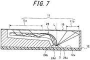
- FIG. 7 is similar to FIG. 6 explained above, and illustrates an instrument illumination device according to a second embodiment of the present invention.
- the light guide plate 24 has a bottom face 24d of a light source side end 24b, which is flat in the whole area and opposite to the bottom face 12a.
- the cut-out slope 14c of the light guide plate 14 according to the first embodiment is not provided.
- An end face 24a of the light source side end 14b is disposed immediately above the optical axis L of the LED 5.
- the end face 24a is disposed on the optical axis L of the LED 5
- at least a part of the light guide side end 14b splits the illumination light into the light amount for entering the light guide plate 24 and the light amount for directly illuminating the auxiliary illumination area 11b of the dial plate 16.
- instrument illumination device according to the present invention is not limited to the specific configuration of the above embodiments and various changes may be made within the scope of the present invention as being encompassed thereby.
- the cut-out slope 14c according to the instrument illumination device of the above embodiments is formed at the half angle ⁇ (here, ⁇ is approximately 60 degrees) from the vertical direction along the optical axis L as illustrated in FIG. 6 such that the illumination light is split into two halves, the angle is not limited thereto.
- the shape, the number and the materials of the light source side ends 14b, 24b and the cut-out slope 14c are not specifically limited, so long as the illumination light is homogeneously split in accordance with the area ratio of the main illumination area 11a and the auxiliary illumination area 11b.
- instrument illumination devices are described as applicable to vehicle indicators installed in a vehicle interior, the instrument illumination device is not limited to such specific application, but may also be used for other display devices of a vehicle, or for a backlight of a liquid crystal display.
Description
- The present invention relates to an instrument illumination device for a vehicle, and more specifically, to an instrument illumination device enabling homogeneous illumination to an instrument face regardless of directionality and the number of light sources.
- An instrument illumination device for a vehicle, such as that as illustrated in
FIG. 8 , has been known (see, for example, Japanese Patent Application Laid-Open Publication No.2010-139296 - This type of instrument illumination device is provided, inside a
housing 2 of a vehicle instrument device 1, with acircuit board 3 that is made of synthetic resin as illustrated inFIG. 9 . - To an
inner face 3a of thecircuit board 3, asmall substrate 3b in the form of a small piece is fixedly attached opposite to anend face 4a of alight guide plate 4 of an arcuate shape, as illustrated inFIG 8 . - The
small substrate 3b has anLED 5 mounted thereon for serving as a light source of the illumination light to enter thelight guide plate 4. When theLED 5 is activated, the illumination light substantially entirely enters theend faces 4a of thelight guide plate 4. - The function of such a conventional instrument illumination device will be described below.
- In the conventional instrument illumination device configured as described above, as illustrated in
FIG 8 orFIG. 9 , the illumination light from theLED 5 having entered theend face 4a of thelight guide plate 4 is reflected within thelight guide plate 4 and dispersed along a circumferential direction to illuminate adial plate 16 from a rear side thereof in a main illumination area "a" illustrated inFIG 9 . - On this occasion, having high directionality, the illumination light of the
LED 5 substantially entirely enters thelight guide plate 4 from theend faces 4a and thereby an area "b" of thedial plate 16 immediately above theLED 5 is illuminated by a backlight. Devices of this kind are described inUS 2009/0316382A1 ,GB 2472078A EP 2015126 A1 . - However, in such a conventional instrument illumination device, depending upon the ornamental design of the dial plate, there may be an instance wherein not only the area "b" immediately above the
LED 5, but also other area, such as an auxiliary illumination area "c" of an auxiliary instrument, for example, requires homogeneous illumination light as is the case with the main illumination area 1. - Accordingly, it is an object of the present invention to provide an instrument illumination device that enables homogeneous illumination light in a broad area, without increasing the number of light sources, and thereby enhancing the freedom degree of the ornamental designing process.
- In order to achieve the above object, an instrument illumination device according to the present invention includes a light source disposed in an instrument housing, a dial plate that covers the instrument housing and uses illumination light from the light source as a backlight, and a light guide plate disposed between the light course and the dial plate, and is provided with a main illumination area using the backlight transmitted through the light guide plate for a main display of the dial plate and an auxiliary illumination area that is not opposite to the light guide plate, wherein
the instrument illumination further comprises means for splitting the illumination light from the light source into a light amount for travelling inside the light guide plate and another light amount to be externally dispersed, in accordance with an area ratio of the main illumination area and the auxiliary illumination area. - With the instrument illumination device according to the present invention, the illumination light from the light source is split into two homogeneous light amounts: i.e., the light amount for travelling through the light guide plate and the light amount to be dispersed outside the light guide plate, in accordance with the area ratio of the main illumination area and the auxiliary illumination area. Thus, the instrument illumination device according to the present invention enables
homogeneous illumination light broadly in both of the main illumination area and the auxiliary illumination area without increasing the number of light sources, and thereby enhancing the freedom degree of the ornamental designing process.
Accordingly, the invention provides an instrument illumination device as defined in the appended claims. -
-
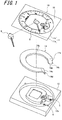
FIG.1 is an exploded perspective view of an instrument illumination device for a vehicle according to a first embodiment of the present invention, suitable for explaining an overall structure. -
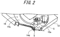
FIG.2 is an enlarged perspective view, partly in cross-section, of a main section of the instrument illumination device according to the first embodiment. -
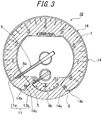
FIG.3 is an elevation view of a light guide plate of the instrument illumination device having a dial plate mounted thereon according to the first embodiment. -
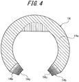
FIG.4 is an elevation view of the light guide plate of the instrument illumination device according to the first embodiment. -
FIG.5 is an elevation view illustrating a positional relationship between the light guide plate and a light source of the instrument illumination device according to the first embodiment. -
FIG.6 is a longitudinal-sectional view illustrating the positional relationship between the light guide plate and the light source of the instrument illumination device according to the first embodiment. -
FIG.7 is a longitudinal-sectional view illustrating the positional relationship between the light guide plate and the light source of the instrument illumination device according to a second embodiment. -
FIG.8 is an elevation view illustrating the positional relationship between the light guide plate and the light source of one example of the conventional instrument illumination device. -
FIG.9 is a longitudinal-sectional view illustrating the positional relationship between the light guide plate and the light source of another example of the conventional instrument illumination device. - The instrument illumination device according to the preferred embodiments of the present invention will be described below with reference to the accompanying drawings.
- It is noted that components with the same or similar structure and/or function as those of the conventional instrument illumination device as described above are denoted by the corresponding reference numerals.
-
FIG 1 to FIG. 6 illustrate the instrument illumination device for a vehicle according to the preferred embodiments. - The configuration of the instrument illumination device according to the first embodiment will be described first of all. In the present embodiment, an instrument panel is to be located in front of a driver's seat inside a vehicle, wherein an
instrument illumination device 10 is provided for illuminating an indicator that indicates the vehicle speed or the engine revolution on adial 8 of adial plate 16 by an angular position of a rotary needle 9. -
FIG 1 to FIG 6 illustrate theinstrument illumination device 10 according to a first embodiment. As illustrated inFIG 2 , a pair oflight sources LEDs bottom face 12a in aninstrumental housing 12. - As illustrated in
FIG. 3 , adial plate 16 covering a front opening of theinstrumental housing 12 has anillumination area 11 including amain illumination area 11a provided with amain dial 8a for displaying the revolution and anauxiliary illumination area 11b provided with anauxiliary dial 8b for displaying a water temperature. - The
main illumination area 11a is in the shape of a ring having a cut-out at a lower part thereof. - The
auxiliary illumination area 11b fills the cut-out and connects themain illumination area 11a. Accordingly, themain illumination area 11a and theauxiliary illumination area 11b together form theillumination area 11 that may transmit illumination light on an entire area thereof - Illumination light from the
LEDs illumination area 11 in the ring shape from a rear side thereof, as backlight. Alight guide plate 14 is provided between theLED 5 and thedial plate 16 such that the transmitted illumination light looks approximately homogeneous from inside the vehicle without generating heterogeneous illumination light, such as pointed illumination light. - The
light guide plate 14 according to the first embodiment is in the approximate shape of a horseshoe in a plane view and mounted in thehousing member 12 such that a flatupper surface 14a is opposite to a rear face of themain illumination area 11a in parallel thereto. - As illustrated in
FIG. 6 , edge portions where thelight guide plate 14 is cut out are bent approximately 90 degrees toward theLEDs 5 such that each light source side ends 14b, 14b renders abottom face 14d opposing thebottom face 12a in parallel thereto. - According to the first embodiment, the light
source side end 14b has a cut-outslope 14c of the semi-cylindrical shape. Thereby, the illumination light from theLED 5 around an optical axis L is split into light amount for entering a part of thebottom face 14d and travelling through thelight guide plate 14 to illuminate themain illumination area 11a, and a light amount for directly illuminating theauxiliary illumination area 11b of thedial plate 16. - According to the first embodiment, the cut-out
slope 14c is formed at a half angle α (here, α is approximately 60 degrees) from a vertical direction along the optical axis L illustrated inFIG 6 so as to split the light amount into two halves. - According to the first embodiment, furthermore, a gap between the pair of
LEDs FIG. 5 , which is the distance enabling the illumination light in themain illumination area 11a and that in theauxiliary illumination area 11b to overlap with each other for complement where the light amount in each of the areas reduces. - Next, the advantageous effects of the first embodiment will be described.
- According to the first embodiment, when the
LED 5 is activated, the illumination light centering the optical axis L enters thelight guide plate 14 from thebottom face 14d of the lightsource side end 14b to travel through thelight guide plate 14 and illuminate themain illumination area 11a. - Also, since the cut-out
slope 14c is formed at the half angle α, which splits the light amount into two halves from the vertical direction along the optical axis L as illustrated inFIG. 6 , the illumination light from theLED 5 exceeding the half angle α from the optical axis L is distributed to directly illuminate theauxiliary illumination area 11b of thedial plate 16. - As described above, the illumination light from the
LEDs light guide plate 14 and the light amount to be dispersed outside thelight guide plate 14, in accordance with an area ratio of themain illumination area 11a and theauxiliary illumination area 11b. - Accordingly, it is possible to ensure that both of the
main illumination area 11a and theauxiliary illumination area 11b are homogeneously illuminated by the illumination light. - Also, since the pair of
LEDs LEDs main illumination area 11a and theauxiliary illumination area 11b, thereby the homogeneous light may be obtained in a broad area. - Accordingly, the backlight may be obtained in a broad area without the need to increase the number of light sources, thereby enhancing the freedom degree of the ornamental designing process.
- Further, since the cut-out
slope 14c of the embodiment 1 is formed in a cut-out process, distribution of the light amount may be easily adjusted. -
FIG. 7 is similar toFIG. 6 explained above, and illustrates an instrument illumination device according to a second embodiment of the present invention. - The components of the second embodiment, which are the same as, or similar to, those of the instrument illumination device according to the first embodiment, are denoted by the same reference numerals.
- According to the second embodiment, the
light guide plate 24 has abottom face 24d of a lightsource side end 24b, which is flat in the whole area and opposite to thebottom face 12a. However, the cut-outslope 14c of thelight guide plate 14 according to the first embodiment is not provided. - An
end face 24a of the light sourceside end 14b is disposed immediately above the optical axis L of theLED 5. - Next, the advantageous effects of the second embodiment will be described.
- According to the instrument illumination device of the second embodiment, in addition to the effects of the instrument illumination device according to the first embodiment, since the
end face 24a is disposed on the optical axis L of theLED 5, at least a part of the lightguide side end 14b splits the illumination light into the light amount for entering thelight guide plate 24 and the light amount for directly illuminating theauxiliary illumination area 11b of thedial plate 16. - Other configurations and effects are the same, or similar to, those of the first embodiment and thus superfluous description is omitted for the sake of clarity.
- Although the preferred embodiments of the present invention have been described above in detail with reference to the drawings, the instrument illumination device according to the present invention is not limited to the specific configuration of the above embodiments and various changes may be made within the scope of the present invention as being encompassed thereby.
- For example, although the cut-out
slope 14c according to the instrument illumination device of the above embodiments is formed at the half angle α (here, α is approximately 60 degrees) from the vertical direction along the optical axis L as illustrated inFIG. 6 such that the illumination light is split into two halves, the angle is not limited thereto. Also, the shape, the number and the materials of the light source side ends 14b, 24b and the cut-outslope 14c are not specifically limited, so long as the illumination light is homogeneously split in accordance with the area ratio of themain illumination area 11a and theauxiliary illumination area 11b. - Although the instrument illumination devices according to the above embodiments are described as applicable to vehicle indicators installed in a vehicle interior, the instrument illumination device is not limited to such specific application, but may also be used for other display devices of a vehicle, or for a backlight of a liquid crystal display.
-
- 5
- Light source (LEDs)
- 10
- Instrument illumination device
- 11
- Illumination area
- 11a
- Main illumination area
- 11b
- Auxiliary illumination area
- 14, 24
- Light guide plate
- 14b, 24b
- Light source side end
- 14d, 24d
- Bottom face
Claims (1)
- An instrument illumination device (10) comprising a light source (5) disposed in an instrument housing (12), a dial plate (16) that covers the instrument housing and uses illumination light from the light source as a backlight, and a light guide plate (14) disposed between the light source and the dial plate, characterised in that the instrument illumination device is provided with a main illumination area (11a) using the backlight travelling through the light guide plate for a main display of the dial plate and an auxiliary illumination area (11b) that is not facing the light guide plate, wherein
the light guide plate comprises a cut out slope (14c) for splitting the illumination light from the light source into a light amount for travelling inside the light guide plate and another light amount to be externally dispersed outside the light guide plate in accordance with an area ratio of the main illumination and the auxiliary illumination area.
Applications Claiming Priority (1)
| Application Number | Priority Date | Filing Date | Title |
|---|---|---|---|
| JP2011149740A JP5642631B2 (en) | 2011-07-06 | 2011-07-06 | Instrument lighting device |
Publications (2)
| Publication Number | Publication Date |
|---|---|
| EP2543976A1 EP2543976A1 (en) | 2013-01-09 |
| EP2543976B1 true EP2543976B1 (en) | 2018-06-20 |
Family
ID=46508223
Family Applications (1)
| Application Number | Title | Priority Date | Filing Date |
|---|---|---|---|
| EP12169978.9A Not-in-force EP2543976B1 (en) | 2011-07-06 | 2012-05-30 | Instrument illumination device |
Country Status (4)
| Country | Link |
|---|---|
| US (1) | US8840260B2 (en) |
| EP (1) | EP2543976B1 (en) |
| JP (1) | JP5642631B2 (en) |
| CN (1) | CN102865885B (en) |
Families Citing this family (9)
| Publication number | Priority date | Publication date | Assignee | Title |
|---|---|---|---|---|
| JP5828804B2 (en) * | 2012-05-24 | 2015-12-09 | カルソニックカンセイ株式会社 | Dial illumination structure |
| JP5962719B2 (en) * | 2013-09-17 | 2016-08-03 | 株式会社デンソー | Vehicle display device |
| US9937849B2 (en) * | 2013-12-02 | 2018-04-10 | Continental Automotive Systems, Inc. | Gauge 360 illumination lightguide |
| US9568655B2 (en) * | 2013-12-26 | 2017-02-14 | Visteon Global Technologies, Inc. | Backlight assembly |
| US9677918B2 (en) * | 2014-10-06 | 2017-06-13 | Continental Automotive Systems, Inc. | Light propagation and even distribution using air channels |
| US10031277B2 (en) * | 2015-11-30 | 2018-07-24 | Continental Automotive Systems, Inc. | Light guide assembly |
| WO2017147541A1 (en) * | 2016-02-26 | 2017-08-31 | Continental Automotive Systems, Inc. | Light guide with chaplet tick marks |
| US10914430B2 (en) | 2017-12-31 | 2021-02-09 | Google Llc | Smart-home device light rings with lens spacing for uniform output |
| JP2019215276A (en) * | 2018-06-13 | 2019-12-19 | 株式会社デンソー | Display device |
Citations (2)
| Publication number | Priority date | Publication date | Assignee | Title |
|---|---|---|---|---|
| JPH10281823A (en) * | 1997-04-03 | 1998-10-23 | Yazaki Corp | Lighting device for measuring instrument |
| JP2001281008A (en) * | 2000-03-31 | 2001-10-10 | Nippon Seiki Co Ltd | Lighting system |
Family Cites Families (10)
| Publication number | Priority date | Publication date | Assignee | Title |
|---|---|---|---|---|
| JP3987667B2 (en) * | 1999-12-01 | 2007-10-10 | カルソニックカンセイ株式会社 | Vehicle instrument |
| JP2005037265A (en) * | 2003-07-16 | 2005-02-10 | Calsonic Kansei Corp | Indicating instrument for car |
| EP2015127A1 (en) * | 2007-07-10 | 2009-01-14 | C.R.F. Società Consortile per Azioni | Light emitting diode with a beam shaping device for backlighting a display or a dashboard |
| DE102008008531A1 (en) * | 2008-02-11 | 2009-08-13 | Robert Bosch Gmbh | Underfloor hands with passive illuminant |
| US7771069B2 (en) * | 2008-03-05 | 2010-08-10 | Denso International America, Inc. | Three-dimensional lighted gauge |
| WO2009128516A1 (en) * | 2008-04-17 | 2009-10-22 | 株式会社フジクラ | Display device |
| US8016441B2 (en) * | 2008-06-24 | 2011-09-13 | Continental Automotive Systems Us, Inc. | One LED illuminated cluster |
| US7758195B2 (en) * | 2008-07-24 | 2010-07-20 | Honda Motor Co., Ltd. | Dial plate with diffuse lighting |
| JP5384924B2 (en) | 2008-12-10 | 2014-01-08 | 矢崎総業株式会社 | Light guide plate |
| GB2472078A (en) * | 2009-07-23 | 2011-01-26 | Visteon Global Tech Inc | A light-pipe for illuminating a display area |
-
2011
- 2011-07-06 JP JP2011149740A patent/JP5642631B2/en not_active Expired - Fee Related
-
2012
- 2012-05-30 EP EP12169978.9A patent/EP2543976B1/en not_active Not-in-force
- 2012-05-31 US US13/484,523 patent/US8840260B2/en not_active Expired - Fee Related
- 2012-06-28 CN CN201210218949.XA patent/CN102865885B/en not_active Expired - Fee Related
Patent Citations (2)
| Publication number | Priority date | Publication date | Assignee | Title |
|---|---|---|---|---|
| JPH10281823A (en) * | 1997-04-03 | 1998-10-23 | Yazaki Corp | Lighting device for measuring instrument |
| JP2001281008A (en) * | 2000-03-31 | 2001-10-10 | Nippon Seiki Co Ltd | Lighting system |
Also Published As
| Publication number | Publication date |
|---|---|
| US8840260B2 (en) | 2014-09-23 |
| JP2013015473A (en) | 2013-01-24 |
| CN102865885A (en) | 2013-01-09 |
| US20130010452A1 (en) | 2013-01-10 |
| CN102865885B (en) | 2016-04-13 |
| JP5642631B2 (en) | 2014-12-17 |
| EP2543976A1 (en) | 2013-01-09 |
Similar Documents
| Publication | Publication Date | Title |
|---|---|---|
| EP2543976B1 (en) | Instrument illumination device | |
| US10072955B2 (en) | Indicator member, indicator unit and indicator instrument | |
| JP5477001B2 (en) | Illumination display device for instrument panel | |
| US10160323B2 (en) | Vehicle instrument panel having three-dimensional illumination effect | |
| US8662689B2 (en) | Pointer-type meter | |
| EP2666659B1 (en) | Display illumination structure | |
| US20080282588A1 (en) | Display apparatus | |
| JP2012108470A (en) | Head-up display device | |
| JP5830345B2 (en) | Meter device | |
| JP2009143409A (en) | Vehicle interior lighting system | |
| JP2015137935A (en) | Dial illumination structure | |
| JP2010048743A (en) | Display | |
| US9121737B2 (en) | Instrumental device | |
| JP2011246082A (en) | Display device | |
| JP2009186400A (en) | Lighting structure of instrument for vehicle | |
| JP2004325312A (en) | Light guide panel, and measuring instrument for vehicle using the same | |
| EP3174035A1 (en) | Light-emitting device | |
| JP6056244B2 (en) | Pointer-type instrument device | |
| JP2012073220A (en) | Instrument device | |
| JP6507889B2 (en) | Display device | |
| JP6118171B2 (en) | Light guide plate for instrument | |
| JP6148533B2 (en) | LCD lighting device | |
| JP5775763B2 (en) | Vehicle instrument | |
| JP2016006385A (en) | Lighting system of vehicular instrument | |
| JP2007062478A (en) | Display device for vehicle |
Legal Events
| Date | Code | Title | Description |
|---|---|---|---|
| PUAI | Public reference made under article 153(3) epc to a published international application that has entered the european phase |
Free format text: ORIGINAL CODE: 0009012 |
|
| AK | Designated contracting states |
Kind code of ref document: A1 Designated state(s): AL AT BE BG CH CY CZ DE DK EE ES FI FR GB GR HR HU IE IS IT LI LT LU LV MC MK MT NL NO PL PT RO RS SE SI SK SM TR |
|
| AX | Request for extension of the european patent |
Extension state: BA ME |
|
| 17P | Request for examination filed |
Effective date: 20130613 |
|
| RBV | Designated contracting states (corrected) |
Designated state(s): AL AT BE BG CH CY CZ DE DK EE ES FI FR GB GR HR HU IE IS IT LI LT LU LV MC MK MT NL NO PL PT RO RS SE SI SK SM TR |
|
| STAA | Information on the status of an ep patent application or granted ep patent |
Free format text: STATUS: EXAMINATION IS IN PROGRESS |
|
| 17Q | First examination report despatched |
Effective date: 20170321 |
|
| GRAP | Despatch of communication of intention to grant a patent |
Free format text: ORIGINAL CODE: EPIDOSNIGR1 |
|
| STAA | Information on the status of an ep patent application or granted ep patent |
Free format text: STATUS: GRANT OF PATENT IS INTENDED |
|
| INTG | Intention to grant announced |
Effective date: 20180314 |
|
| GRAS | Grant fee paid |
Free format text: ORIGINAL CODE: EPIDOSNIGR3 |
|
| GRAA | (expected) grant |
Free format text: ORIGINAL CODE: 0009210 |
|
| STAA | Information on the status of an ep patent application or granted ep patent |
Free format text: STATUS: THE PATENT HAS BEEN GRANTED |
|
| AK | Designated contracting states |
Kind code of ref document: B1 Designated state(s): AL AT BE BG CH CY CZ DE DK EE ES FI FR GB GR HR HU IE IS IT LI LT LU LV MC MK MT NL NO PL PT RO RS SE SI SK SM TR |
|
| REG | Reference to a national code |
Ref country code: GB Ref legal event code: FG4D |
|
| REG | Reference to a national code |
Ref country code: IE Ref legal event code: FG4D |
|
| REG | Reference to a national code |
Ref country code: AT Ref legal event code: REF Ref document number: 1010932 Country of ref document: AT Kind code of ref document: T Effective date: 20180715 |
|
| REG | Reference to a national code |
Ref country code: DE Ref legal event code: R096 Ref document number: 602012047602 Country of ref document: DE |
|
| REG | Reference to a national code |
Ref country code: NL Ref legal event code: MP Effective date: 20180620 |
|
| PG25 | Lapsed in a contracting state [announced via postgrant information from national office to epo] |
Ref country code: NO Free format text: LAPSE BECAUSE OF FAILURE TO SUBMIT A TRANSLATION OF THE DESCRIPTION OR TO PAY THE FEE WITHIN THE PRESCRIBED TIME-LIMIT Effective date: 20180920 Ref country code: FI Free format text: LAPSE BECAUSE OF FAILURE TO SUBMIT A TRANSLATION OF THE DESCRIPTION OR TO PAY THE FEE WITHIN THE PRESCRIBED TIME-LIMIT Effective date: 20180620 Ref country code: BG Free format text: LAPSE BECAUSE OF FAILURE TO SUBMIT A TRANSLATION OF THE DESCRIPTION OR TO PAY THE FEE WITHIN THE PRESCRIBED TIME-LIMIT Effective date: 20180920 Ref country code: LT Free format text: LAPSE BECAUSE OF FAILURE TO SUBMIT A TRANSLATION OF THE DESCRIPTION OR TO PAY THE FEE WITHIN THE PRESCRIBED TIME-LIMIT Effective date: 20180620 Ref country code: SE Free format text: LAPSE BECAUSE OF FAILURE TO SUBMIT A TRANSLATION OF THE DESCRIPTION OR TO PAY THE FEE WITHIN THE PRESCRIBED TIME-LIMIT Effective date: 20180620 |
|
| REG | Reference to a national code |
Ref country code: LT Ref legal event code: MG4D |
|
| PG25 | Lapsed in a contracting state [announced via postgrant information from national office to epo] |
Ref country code: LV Free format text: LAPSE BECAUSE OF FAILURE TO SUBMIT A TRANSLATION OF THE DESCRIPTION OR TO PAY THE FEE WITHIN THE PRESCRIBED TIME-LIMIT Effective date: 20180620 Ref country code: HR Free format text: LAPSE BECAUSE OF FAILURE TO SUBMIT A TRANSLATION OF THE DESCRIPTION OR TO PAY THE FEE WITHIN THE PRESCRIBED TIME-LIMIT Effective date: 20180620 Ref country code: RS Free format text: LAPSE BECAUSE OF FAILURE TO SUBMIT A TRANSLATION OF THE DESCRIPTION OR TO PAY THE FEE WITHIN THE PRESCRIBED TIME-LIMIT Effective date: 20180620 Ref country code: GR Free format text: LAPSE BECAUSE OF FAILURE TO SUBMIT A TRANSLATION OF THE DESCRIPTION OR TO PAY THE FEE WITHIN THE PRESCRIBED TIME-LIMIT Effective date: 20180921 |
|
| REG | Reference to a national code |
Ref country code: AT Ref legal event code: MK05 Ref document number: 1010932 Country of ref document: AT Kind code of ref document: T Effective date: 20180620 |
|
| PG25 | Lapsed in a contracting state [announced via postgrant information from national office to epo] |
Ref country code: NL Free format text: LAPSE BECAUSE OF FAILURE TO SUBMIT A TRANSLATION OF THE DESCRIPTION OR TO PAY THE FEE WITHIN THE PRESCRIBED TIME-LIMIT Effective date: 20180620 |
|
| PG25 | Lapsed in a contracting state [announced via postgrant information from national office to epo] |
Ref country code: IS Free format text: LAPSE BECAUSE OF FAILURE TO SUBMIT A TRANSLATION OF THE DESCRIPTION OR TO PAY THE FEE WITHIN THE PRESCRIBED TIME-LIMIT Effective date: 20181020 Ref country code: PL Free format text: LAPSE BECAUSE OF FAILURE TO SUBMIT A TRANSLATION OF THE DESCRIPTION OR TO PAY THE FEE WITHIN THE PRESCRIBED TIME-LIMIT Effective date: 20180620 Ref country code: SK Free format text: LAPSE BECAUSE OF FAILURE TO SUBMIT A TRANSLATION OF THE DESCRIPTION OR TO PAY THE FEE WITHIN THE PRESCRIBED TIME-LIMIT Effective date: 20180620 Ref country code: RO Free format text: LAPSE BECAUSE OF FAILURE TO SUBMIT A TRANSLATION OF THE DESCRIPTION OR TO PAY THE FEE WITHIN THE PRESCRIBED TIME-LIMIT Effective date: 20180620 Ref country code: CZ Free format text: LAPSE BECAUSE OF FAILURE TO SUBMIT A TRANSLATION OF THE DESCRIPTION OR TO PAY THE FEE WITHIN THE PRESCRIBED TIME-LIMIT Effective date: 20180620 Ref country code: EE Free format text: LAPSE BECAUSE OF FAILURE TO SUBMIT A TRANSLATION OF THE DESCRIPTION OR TO PAY THE FEE WITHIN THE PRESCRIBED TIME-LIMIT Effective date: 20180620 Ref country code: AT Free format text: LAPSE BECAUSE OF FAILURE TO SUBMIT A TRANSLATION OF THE DESCRIPTION OR TO PAY THE FEE WITHIN THE PRESCRIBED TIME-LIMIT Effective date: 20180620 |
|
| PG25 | Lapsed in a contracting state [announced via postgrant information from national office to epo] |
Ref country code: ES Free format text: LAPSE BECAUSE OF FAILURE TO SUBMIT A TRANSLATION OF THE DESCRIPTION OR TO PAY THE FEE WITHIN THE PRESCRIBED TIME-LIMIT Effective date: 20180620 Ref country code: IT Free format text: LAPSE BECAUSE OF FAILURE TO SUBMIT A TRANSLATION OF THE DESCRIPTION OR TO PAY THE FEE WITHIN THE PRESCRIBED TIME-LIMIT Effective date: 20180620 Ref country code: SM Free format text: LAPSE BECAUSE OF FAILURE TO SUBMIT A TRANSLATION OF THE DESCRIPTION OR TO PAY THE FEE WITHIN THE PRESCRIBED TIME-LIMIT Effective date: 20180620 |
|
| REG | Reference to a national code |
Ref country code: DE Ref legal event code: R097 Ref document number: 602012047602 Country of ref document: DE |
|
| PLBE | No opposition filed within time limit |
Free format text: ORIGINAL CODE: 0009261 |
|
| STAA | Information on the status of an ep patent application or granted ep patent |
Free format text: STATUS: NO OPPOSITION FILED WITHIN TIME LIMIT |
|
| 26N | No opposition filed |
Effective date: 20190321 |
|
| PG25 | Lapsed in a contracting state [announced via postgrant information from national office to epo] |
Ref country code: DK Free format text: LAPSE BECAUSE OF FAILURE TO SUBMIT A TRANSLATION OF THE DESCRIPTION OR TO PAY THE FEE WITHIN THE PRESCRIBED TIME-LIMIT Effective date: 20180620 |
|
| PGFP | Annual fee paid to national office [announced via postgrant information from national office to epo] |
Ref country code: DE Payment date: 20190514 Year of fee payment: 8 |
|
| PG25 | Lapsed in a contracting state [announced via postgrant information from national office to epo] |
Ref country code: SI Free format text: LAPSE BECAUSE OF FAILURE TO SUBMIT A TRANSLATION OF THE DESCRIPTION OR TO PAY THE FEE WITHIN THE PRESCRIBED TIME-LIMIT Effective date: 20180620 |
|
| PGFP | Annual fee paid to national office [announced via postgrant information from national office to epo] |
Ref country code: FR Payment date: 20190410 Year of fee payment: 8 |
|
| PGFP | Annual fee paid to national office [announced via postgrant information from national office to epo] |
Ref country code: GB Payment date: 20190529 Year of fee payment: 8 |
|
| PG25 | Lapsed in a contracting state [announced via postgrant information from national office to epo] |
Ref country code: AL Free format text: LAPSE BECAUSE OF FAILURE TO SUBMIT A TRANSLATION OF THE DESCRIPTION OR TO PAY THE FEE WITHIN THE PRESCRIBED TIME-LIMIT Effective date: 20180620 |
|
| REG | Reference to a national code |
Ref country code: CH Ref legal event code: PL |
|
| PG25 | Lapsed in a contracting state [announced via postgrant information from national office to epo] |
Ref country code: MC Free format text: LAPSE BECAUSE OF FAILURE TO SUBMIT A TRANSLATION OF THE DESCRIPTION OR TO PAY THE FEE WITHIN THE PRESCRIBED TIME-LIMIT Effective date: 20180620 Ref country code: LI Free format text: LAPSE BECAUSE OF NON-PAYMENT OF DUE FEES Effective date: 20190531 Ref country code: CH Free format text: LAPSE BECAUSE OF NON-PAYMENT OF DUE FEES Effective date: 20190531 |
|
| REG | Reference to a national code |
Ref country code: BE Ref legal event code: MM Effective date: 20190531 |
|
| PG25 | Lapsed in a contracting state [announced via postgrant information from national office to epo] |
Ref country code: LU Free format text: LAPSE BECAUSE OF NON-PAYMENT OF DUE FEES Effective date: 20190530 |
|
| PG25 | Lapsed in a contracting state [announced via postgrant information from national office to epo] |
Ref country code: TR Free format text: LAPSE BECAUSE OF FAILURE TO SUBMIT A TRANSLATION OF THE DESCRIPTION OR TO PAY THE FEE WITHIN THE PRESCRIBED TIME-LIMIT Effective date: 20180620 |
|
| PG25 | Lapsed in a contracting state [announced via postgrant information from national office to epo] |
Ref country code: IE Free format text: LAPSE BECAUSE OF NON-PAYMENT OF DUE FEES Effective date: 20190530 |
|
| PG25 | Lapsed in a contracting state [announced via postgrant information from national office to epo] |
Ref country code: BE Free format text: LAPSE BECAUSE OF NON-PAYMENT OF DUE FEES Effective date: 20190531 |
|
| PG25 | Lapsed in a contracting state [announced via postgrant information from national office to epo] |
Ref country code: PT Free format text: LAPSE BECAUSE OF FAILURE TO SUBMIT A TRANSLATION OF THE DESCRIPTION OR TO PAY THE FEE WITHIN THE PRESCRIBED TIME-LIMIT Effective date: 20181022 |
|
| REG | Reference to a national code |
Ref country code: DE Ref legal event code: R119 Ref document number: 602012047602 Country of ref document: DE |
|
| GBPC | Gb: european patent ceased through non-payment of renewal fee |
Effective date: 20200530 |
|
| PG25 | Lapsed in a contracting state [announced via postgrant information from national office to epo] |
Ref country code: FR Free format text: LAPSE BECAUSE OF NON-PAYMENT OF DUE FEES Effective date: 20200531 Ref country code: GB Free format text: LAPSE BECAUSE OF NON-PAYMENT OF DUE FEES Effective date: 20200530 |
|
| PG25 | Lapsed in a contracting state [announced via postgrant information from national office to epo] |
Ref country code: CY Free format text: LAPSE BECAUSE OF FAILURE TO SUBMIT A TRANSLATION OF THE DESCRIPTION OR TO PAY THE FEE WITHIN THE PRESCRIBED TIME-LIMIT Effective date: 20180620 Ref country code: DE Free format text: LAPSE BECAUSE OF NON-PAYMENT OF DUE FEES Effective date: 20201201 |
|
| PG25 | Lapsed in a contracting state [announced via postgrant information from national office to epo] |
Ref country code: HU Free format text: LAPSE BECAUSE OF FAILURE TO SUBMIT A TRANSLATION OF THE DESCRIPTION OR TO PAY THE FEE WITHIN THE PRESCRIBED TIME-LIMIT; INVALID AB INITIO Effective date: 20120530 Ref country code: MT Free format text: LAPSE BECAUSE OF FAILURE TO SUBMIT A TRANSLATION OF THE DESCRIPTION OR TO PAY THE FEE WITHIN THE PRESCRIBED TIME-LIMIT Effective date: 20180620 |
|
| PG25 | Lapsed in a contracting state [announced via postgrant information from national office to epo] |
Ref country code: MK Free format text: LAPSE BECAUSE OF FAILURE TO SUBMIT A TRANSLATION OF THE DESCRIPTION OR TO PAY THE FEE WITHIN THE PRESCRIBED TIME-LIMIT Effective date: 20180620 |