EP2543924A2 - LED apparatus - Google Patents
LED apparatus Download PDFInfo
- Publication number
- EP2543924A2 EP2543924A2 EP12186829A EP12186829A EP2543924A2 EP 2543924 A2 EP2543924 A2 EP 2543924A2 EP 12186829 A EP12186829 A EP 12186829A EP 12186829 A EP12186829 A EP 12186829A EP 2543924 A2 EP2543924 A2 EP 2543924A2
- Authority
- EP
- European Patent Office
- Prior art keywords
- led
- shield
- lens
- secondary lens
- led apparatus
- Prior art date
- Legal status (The legal status is an assumption and is not a legal conclusion. Google has not performed a legal analysis and makes no representation as to the accuracy of the status listed.)
- Granted
Links
Images




Classifications
-
- F—MECHANICAL ENGINEERING; LIGHTING; HEATING; WEAPONS; BLASTING
- F21—LIGHTING
- F21S—NON-PORTABLE LIGHTING DEVICES; SYSTEMS THEREOF; VEHICLE LIGHTING DEVICES SPECIALLY ADAPTED FOR VEHICLE EXTERIORS
- F21S8/00—Lighting devices intended for fixed installation
-
- F—MECHANICAL ENGINEERING; LIGHTING; HEATING; WEAPONS; BLASTING
- F21—LIGHTING
- F21S—NON-PORTABLE LIGHTING DEVICES; SYSTEMS THEREOF; VEHICLE LIGHTING DEVICES SPECIALLY ADAPTED FOR VEHICLE EXTERIORS
- F21S8/00—Lighting devices intended for fixed installation
- F21S8/08—Lighting devices intended for fixed installation with a standard
- F21S8/085—Lighting devices intended for fixed installation with a standard of high-built type, e.g. street light
- F21S8/086—Lighting devices intended for fixed installation with a standard of high-built type, e.g. street light with lighting device attached sideways of the standard, e.g. for roads and highways
-
- F—MECHANICAL ENGINEERING; LIGHTING; HEATING; WEAPONS; BLASTING
- F21—LIGHTING
- F21V—FUNCTIONAL FEATURES OR DETAILS OF LIGHTING DEVICES OR SYSTEMS THEREOF; STRUCTURAL COMBINATIONS OF LIGHTING DEVICES WITH OTHER ARTICLES, NOT OTHERWISE PROVIDED FOR
- F21V13/00—Producing particular characteristics or distribution of the light emitted by means of a combination of elements specified in two or more of main groups F21V1/00 - F21V11/00
- F21V13/02—Combinations of only two kinds of elements
-
- F—MECHANICAL ENGINEERING; LIGHTING; HEATING; WEAPONS; BLASTING
- F21—LIGHTING
- F21V—FUNCTIONAL FEATURES OR DETAILS OF LIGHTING DEVICES OR SYSTEMS THEREOF; STRUCTURAL COMBINATIONS OF LIGHTING DEVICES WITH OTHER ARTICLES, NOT OTHERWISE PROVIDED FOR
- F21V19/00—Fastening of light sources or lamp holders
- F21V19/001—Fastening of light sources or lamp holders the light sources being semiconductors devices, e.g. LEDs
-
- F—MECHANICAL ENGINEERING; LIGHTING; HEATING; WEAPONS; BLASTING
- F21—LIGHTING
- F21V—FUNCTIONAL FEATURES OR DETAILS OF LIGHTING DEVICES OR SYSTEMS THEREOF; STRUCTURAL COMBINATIONS OF LIGHTING DEVICES WITH OTHER ARTICLES, NOT OTHERWISE PROVIDED FOR
- F21V5/00—Refractors for light sources
- F21V5/008—Combination of two or more successive refractors along an optical axis
-
- F—MECHANICAL ENGINEERING; LIGHTING; HEATING; WEAPONS; BLASTING
- F21—LIGHTING
- F21V—FUNCTIONAL FEATURES OR DETAILS OF LIGHTING DEVICES OR SYSTEMS THEREOF; STRUCTURAL COMBINATIONS OF LIGHTING DEVICES WITH OTHER ARTICLES, NOT OTHERWISE PROVIDED FOR
- F21V5/00—Refractors for light sources
- F21V5/04—Refractors for light sources of lens shape
-
- G—PHYSICS
- G02—OPTICS
- G02B—OPTICAL ELEMENTS, SYSTEMS OR APPARATUS
- G02B19/00—Condensers, e.g. light collectors or similar non-imaging optics
- G02B19/0004—Condensers, e.g. light collectors or similar non-imaging optics characterised by the optical means employed
- G02B19/0028—Condensers, e.g. light collectors or similar non-imaging optics characterised by the optical means employed refractive and reflective surfaces, e.g. non-imaging catadioptric systems
-
- G—PHYSICS
- G02—OPTICS
- G02B—OPTICAL ELEMENTS, SYSTEMS OR APPARATUS
- G02B19/00—Condensers, e.g. light collectors or similar non-imaging optics
- G02B19/0033—Condensers, e.g. light collectors or similar non-imaging optics characterised by the use
- G02B19/0047—Condensers, e.g. light collectors or similar non-imaging optics characterised by the use for use with a light source
- G02B19/0061—Condensers, e.g. light collectors or similar non-imaging optics characterised by the use for use with a light source the light source comprising a LED
- G02B19/0066—Condensers, e.g. light collectors or similar non-imaging optics characterised by the use for use with a light source the light source comprising a LED in the form of an LED array
-
- F—MECHANICAL ENGINEERING; LIGHTING; HEATING; WEAPONS; BLASTING
- F21—LIGHTING
- F21S—NON-PORTABLE LIGHTING DEVICES; SYSTEMS THEREOF; VEHICLE LIGHTING DEVICES SPECIALLY ADAPTED FOR VEHICLE EXTERIORS
- F21S8/00—Lighting devices intended for fixed installation
- F21S8/08—Lighting devices intended for fixed installation with a standard
-
- F—MECHANICAL ENGINEERING; LIGHTING; HEATING; WEAPONS; BLASTING
- F21—LIGHTING
- F21V—FUNCTIONAL FEATURES OR DETAILS OF LIGHTING DEVICES OR SYSTEMS THEREOF; STRUCTURAL COMBINATIONS OF LIGHTING DEVICES WITH OTHER ARTICLES, NOT OTHERWISE PROVIDED FOR
- F21V11/00—Screens not covered by groups F21V1/00, F21V3/00, F21V7/00 or F21V9/00
- F21V11/16—Screens not covered by groups F21V1/00, F21V3/00, F21V7/00 or F21V9/00 using sheets without apertures, e.g. fixed
-
- F—MECHANICAL ENGINEERING; LIGHTING; HEATING; WEAPONS; BLASTING
- F21—LIGHTING
- F21W—INDEXING SCHEME ASSOCIATED WITH SUBCLASSES F21K, F21L, F21S and F21V, RELATING TO USES OR APPLICATIONS OF LIGHTING DEVICES OR SYSTEMS
- F21W2131/00—Use or application of lighting devices or systems not provided for in codes F21W2102/00-F21W2121/00
- F21W2131/10—Outdoor lighting
- F21W2131/103—Outdoor lighting of streets or roads
-
- F—MECHANICAL ENGINEERING; LIGHTING; HEATING; WEAPONS; BLASTING
- F21—LIGHTING
- F21Y—INDEXING SCHEME ASSOCIATED WITH SUBCLASSES F21K, F21L, F21S and F21V, RELATING TO THE FORM OR THE KIND OF THE LIGHT SOURCES OR OF THE COLOUR OF THE LIGHT EMITTED
- F21Y2105/00—Planar light sources
- F21Y2105/10—Planar light sources comprising a two-dimensional [2D] array of point-like light-generating elements
-
- F—MECHANICAL ENGINEERING; LIGHTING; HEATING; WEAPONS; BLASTING
- F21—LIGHTING
- F21Y—INDEXING SCHEME ASSOCIATED WITH SUBCLASSES F21K, F21L, F21S and F21V, RELATING TO THE FORM OR THE KIND OF THE LIGHT SOURCES OR OF THE COLOUR OF THE LIGHT EMITTED
- F21Y2115/00—Light-generating elements of semiconductor light sources
- F21Y2115/10—Light-emitting diodes [LED]
Definitions
- the invention relates generally to the field of lighting systems and, more particularly, to apparatus for utilizing LED (light-emitting diode) sources for illuminating areas with a predefined pattern of light intensity toward a preferential side.
- LED light-emitting diode
- LEDs provide light sources which are energy efficient, and advances in LED technology are providing even greater such efficiencies over time.
- One advantage of using LEDs as light sources is simply that the smaller size of such sources translate into lower material usage within fixtures containing such sources, thus yielding the attendant cost-efficiency.
- Preferred performance requirements for lighting systems for various uses involve freedom of "light spillage" into areas not intended to be lit.
- roadway and parking lot lighting systems have excellent light distribution over areas which are to be lighted, but neighboring regions are as free of light as possible.
- LED fixtures in the prior art having shields have certain shortcomings and disadvantages to which this invention is addressed.
- an improved LED light fixture with directional shield that facilitates accurate manufacture while having an improved effectiveness in light distribution, including avoidance of light distribution to a non-preferential side. It would be desirable that an LED light fixture with directional shielding which is cost-effective in manufacture be able to provide a high level of output for lighting large areas in a preferential direction while minimizing light in a non-preferential direction.
- Another object of this invention is to provide LED lighting apparatus with directional shielding which by its nature facilitates accurate manufacture, including of multi-LED fixtures.
- Another object of this invention is to provide LED lighting apparatus with directional shielding having the above advantages and with improved effectiveness in light distribution, including avoidance of light distribution to a non-preferential side.
- Another object of this invention is to provide LED lighting apparatus with directional shielding which is particularly adaptable for LED fixtures providing a high level of light output for lighting of large areas such as roadways and parking lots.
- Yet another object of this invention is to provide an LED lighting apparatus with directional shielding having the above advantages which directs light using a shield in the above fashion in a cost-effective manner.
- This invention is an LED apparatus for improved illumination toward a preferential side in a downward and outward direction.
- the apparatus is of the type including a mounting board, an LED package thereon with a primary lens having a central axis and a secondary lens member over the primary lens which establishes a light path therebetween.
- the improved apparatus of this invention includes a shield member in the form of a layer which is positioned over the mounting board, LED package and secondary lens member, the shield member having a shield portion and a substantially planar non-shield portion thereabout.
- the shield member has a shield-member aperture aligned with the light path and the shield portion borders the shield-member aperture. It is most preferred that the secondary lens member includes a lens portion and a flange thereabout; and the shield portion extends over a part of the lens portion of the secondary lens member. Highly desirable is where the shield member has a shield-member aperture aligned with the light path and the shield portion borders the shield-member aperture.
- the secondary lens member is asymmetrical and has an illumination pattern with a preferential side and a non-preferential side.
- the shield portion is positioned to intercept light on the non-preferential side.
- Preferred embodiments include a cover which secures the shield member with respect to the secondary lens member, the primary lens and the LED package.
- the cover has an opening aligned with the light path.
- Preferred embodiments have the shield member sandwiched between the cover and the flange of the secondary lens member.
- the flange of the secondary lens member is against the mounting board.
- the sandwiching is of the non-shield portion of the shield member and of the flange of the secondary lens member when the cover is secured in place.
- a resilient gasket is disposed between the shield member and the secondary lens. It is most preferred that the shield portion has a reflective surface facing the secondary lens.
- the LED packages, secondary lens member and shield portion are a plurality of LED packages, secondary lens members and shield portions.
- the LED packages are spaced from one another on the mounting board.
- each secondary lens member is positioned over the primary lens of a corresponding LED package, each primary-lens/secondary-lens-member pair establishes a light path and has a central axis.
- the LED apparatus for illumination toward a preferential side in a downward and outward direction may include a mounting board and an LED package thereon with a primary lens which has a central axis.
- the improvement comprises a shield member in the form of a layer positioned over the mounting board and an LED package.
- the shield member has a shield portion and a substantially planar non-shield portion thereabout.
- downward is used herein for convenience in describing the invention and aspects thereof, but does not in any way mandate usage of the apparatus in any orientation. In other words, “downward” is not limited by the direction of gravity. Thus, if a light fixture incorporating the inventive light-directing LED apparatus disclosed herein is oriented upward rather than downward, or in some laterally-oriented direction, the term “downward” subsumes such meanings.
- the term “downward” has been used since one important application for the inventive apparatus is the lighting of ground surfaces from vertical light poles. Note that the figures primarily show such "downward” direction as generally upward since visualization of the compound outer lens surface of the secondary lens in perspective is best viewed for clarity in such orientation.
- LED package means an assembly including a base, at least one LED (sometimes referred to as “die”) on the base, and a primary lens over the die.
- LED sometimes referred to as “die”
- One or more, typically several, LED packages are arranged on a mounting board in forming that is referred to as an "LED module.”
- LED modules are used as the light source for various innovative lighting fixtures.
- the inventive apparatus will most typically be used in applications when a multiplicity of such devices are arranged on what is referred to as an LED module, one or more of which are used within a lighting fixture to achieve desired illumination.
- LED module one or more of which are used within a lighting fixture to achieve desired illumination.
- Roadway and parking lot lighting are such applications, although there are a great many other applications for such devices.
- FIGURES 1-4 and 9 illustrate an LED apparatus 10 for illumination toward a preferential side 36 in a downward direction 48 and outward direction 49.
- LED apparatus 10 includes a mounting board 12, LED package 14 thereon with primary lens 16 having central axis 18, and secondary lens member 20 over primary lens 16 and establishing light path 22 therebetween.
- the mounting board 12 is connected to a heat sink 54 as shown in FIGURES 1 and 2 .
- One or more, typically several, LED packages 14 are arranged on a mounting board 12 to form what is referred to as an LED module 58.
- One or more LED modules 58 are used as the light source for various innovative lighting fixtures.
- shield member 24 in the form of a layer, is positioned over mounting board 12, LED package 14 and secondary lens member 20.
- Shield member 24 has shield portion 26 and a substantially planar non-shield portion 28 thereabout as seen in FIGURE 6 .
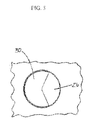
- FIGURES 5 and 6 illustrate that shield member 24 has a shield-member aperture 30 aligned with light path 22 and shield portion 26 borders shield-member aperture 30.
- secondary lens 20 includes a lens portion 32 which is substantially transparent and a flange 34 portion thereabout. Lens portions 32 is adjacent to flange portion 34 as illustrated in FIGURES 7 and 8 . Shield portion 26 extends over a part of lens portion 32 of secondary lens member 20. Secondary lens member 20 is asymmetrical and has an illumination pattern 50 with a preferential side 36 and a non-preferential side 38 as shown in FIGURES 9-11 . Shield portion 26 is positioned to intercept light on non-preferential side 38.
- secondary lens 20 defines preferential side as indicated by reference number 36.
- FIGURES 10 and 11 also indicate, by reference number 38, the direction toward the opposite, non-preferential side 38.
- FIGURE 10 and 11 illustrate a two-dimensional illumination intensity distribution 50 for an embodiment containing an LED package 14, a single primary lens 16 and a single secondary lens 20.
- Pattern 50 in FIGURES 10 and 11 was generated using optical ray-tracing software to simulate the illumination intensity emanating from LED apparatus 10.
- the brightness of illumination pattern 50 in FIGURE 11 illustrates the relative intensity distribution using a shield member layer 24, demonstrating that a very large percentage of the light emanating from apparatus 10 is redirected toward the preferential side 36 by shield member layer 24 of apparatus 10 and only a small amount of trespass light on the non-preferential side 38.
- FIGURE 10 illustrates the relative intensity distribution without the shield member layer 24 present, demonstrating that light is not blocked from the apparatus 10 resulting in a large amount of trespass light on the non-preferential side 38.
- FIGURES 1-4 illustrate that cover 40 secures shield member 24 with respect to secondary lens member 20, primary lens 16 and LED package 14.
- Cover 40 has an opening 42 aligned with the light path 22 as shown in FIGURES 1-3 .
- Shield member 24 is sandwiched between cover 40 and flange 34 of secondary lens member 20
- flange 34 of secondary lens member 20 is sandwiched against mounting board 12.
- shield portion 26 of shield member 24 has a reflective surface 44 facing secondary lens member 20.
- an enclosure barrier member layer such as a gasket 46
- an aluminum layer 56 is sandwiched between the mounting board 12 and the secondary lens member 20 as seen in FIGURE 3 .
- LED apparatus 10 can consist of only one LED package 14 on a mounting board 12 with a corresponding primary lens 16, secondary lens member 20 and shield member 24 or a plurality of LED packages 14 on a mounting board 12 with corresponding primary lenses 16, secondary lens members 20 and shield members 24.
- a plurality of LED packages 14 are spaced from one another on the mounting board 12.
- a plurality of secondary lens members 20 are also present in certain embodiments as illustrated in FIGURE 3 .
- Each secondary lens member 20 is positioned over the primary lens 16 of a corresponding LED package 14.
- Each primary-lens/secondary-lens-member pair 52 establishes a light path 22 and has a central axis 18 as shown in FIGURE 6 .
- a plurality of shield portions 26 of the shield member 24 are also present in certain embodiments as illustrated in FIGURE 3 . As shown in FIGURES 3 and 6 each shield portion 26 is positioned partially over each primary-lens/secondary-lens-member pair 52 thereby to intercept a portion of the light path 22 emitted from the corresponding LED package 14.
Landscapes
- Engineering & Computer Science (AREA)
- General Engineering & Computer Science (AREA)
- Physics & Mathematics (AREA)
- General Physics & Mathematics (AREA)
- Optics & Photonics (AREA)
- Non-Portable Lighting Devices Or Systems Thereof (AREA)
- Securing Globes, Refractors, Reflectors Or The Like (AREA)
- Led Device Packages (AREA)
- Illuminated Signs And Luminous Advertising (AREA)
Abstract
Description
- The invention relates generally to the field of lighting systems and, more particularly, to apparatus for utilizing LED (light-emitting diode) sources for illuminating areas with a predefined pattern of light intensity toward a preferential side.
- There is a continuing need for lighting apparatus which is low-cost and energy efficient. LEDs provide light sources which are energy efficient, and advances in LED technology are providing even greater such efficiencies over time. One advantage of using LEDs as light sources is simply that the smaller size of such sources translate into lower material usage within fixtures containing such sources, thus yielding the attendant cost-efficiency.
- Preferred performance requirements for lighting systems for various uses involve freedom of "light spillage" into areas not intended to be lit. For example, it is preferred that roadway and parking lot lighting systems have excellent light distribution over areas which are to be lighted, but neighboring regions are as free of light as possible. More specifically, there is a need to be able to direct light in a downward and preferential lateral direction while avoiding so-called trespass lighting on neighboring property, while providing lighting to the roadways or parking lots. Satisfying such concerns can be difficult when LEDs are used as light sources, particularly given the fact that in such cases many LEDs are used in individual fixtures.
- Various LED lighting fixtures with light shielding have been developed. Examples of such prior art fixtures are those disclosed in the following United States patents: Patent No.
7,019,334 (Yatsuda, et al ), Patent No.6,972,439 (Kim, et al. ) and Patent Publication Nos:US 2006/0175626 (Wall Jr. ) andUS 2006/0158080 (Nakano et al. ). - LED fixtures in the prior art having shields have certain shortcomings and disadvantages to which this invention is addressed. In particular, there is a need for an improved LED light fixture with directional shield that facilitates accurate manufacture while having an improved effectiveness in light distribution, including avoidance of light distribution to a non-preferential side. It would be desirable that an LED light fixture with directional shielding which is cost-effective in manufacture be able to provide a high level of output for lighting large areas in a preferential direction while minimizing light in a non-preferential direction.
- It is an object of this invention, to provide LED lighting apparatus with directional shielding which overcomes certain problems and shortcoming of the prior art including those referred to above.
- Another object of this invention is to provide LED lighting apparatus with directional shielding which by its nature facilitates accurate manufacture, including of multi-LED fixtures.
- Another object of this invention is to provide LED lighting apparatus with directional shielding having the above advantages and with improved effectiveness in light distribution, including avoidance of light distribution to a non-preferential side.
- Another object of this invention is to provide LED lighting apparatus with directional shielding which is particularly adaptable for LED fixtures providing a high level of light output for lighting of large areas such as roadways and parking lots.
- Yet another object of this invention is to provide an LED lighting apparatus with directional shielding having the above advantages which directs light using a shield in the above fashion in a cost-effective manner.
- These and other objects of the invention will be apparent from the following descriptions and the drawings.
- This invention is an LED apparatus for improved illumination toward a preferential side in a downward and outward direction. The apparatus is of the type including a mounting board, an LED package thereon with a primary lens having a central axis and a secondary lens member over the primary lens which establishes a light path therebetween. The improved apparatus of this invention includes a shield member in the form of a layer which is positioned over the mounting board, LED package and secondary lens member, the shield member having a shield portion and a substantially planar non-shield portion thereabout.
- In certain preferred embodiments the shield member has a shield-member aperture aligned with the light path and the shield portion borders the shield-member aperture. It is most preferred that the secondary lens member includes a lens portion and a flange thereabout; and the shield portion extends over a part of the lens portion of the secondary lens member. Highly desirable is where the shield member has a shield-member aperture aligned with the light path and the shield portion borders the shield-member aperture.
- Preferably the secondary lens member is asymmetrical and has an illumination pattern with a preferential side and a non-preferential side. The shield portion is positioned to intercept light on the non-preferential side. Preferred embodiments include a cover which secures the shield member with respect to the secondary lens member, the primary lens and the LED package. The cover has an opening aligned with the light path.
- Preferred embodiments have the shield member sandwiched between the cover and the flange of the secondary lens member. Preferably the flange of the secondary lens member is against the mounting board. The sandwiching is of the non-shield portion of the shield member and of the flange of the secondary lens member when the cover is secured in place.
- In certain embodiments, a resilient gasket is disposed between the shield member and the secondary lens. It is most preferred that the shield portion has a reflective surface facing the secondary lens.
- In highly preferred embodiments, the LED packages, secondary lens member and shield portion are a plurality of LED packages, secondary lens members and shield portions. Preferably the LED packages are spaced from one another on the mounting board. It is highly preferred that each secondary lens member is positioned over the primary lens of a corresponding LED package, each primary-lens/secondary-lens-member pair establishes a light path and has a central axis. Also preferred is where there is a plurality of shield portions of the shield member. Each shield portion is positioned partially over each primary-lens/secondary-lens-member pair thereby to intercept a portion of the light emitted from the corresponding LED package.
- The LED apparatus for illumination toward a preferential side in a downward and outward direction, in some embodiments, may include a mounting board and an LED package thereon with a primary lens which has a central axis. The improvement comprises a shield member in the form of a layer positioned over the mounting board and an LED package. The shield member has a shield portion and a substantially planar non-shield portion thereabout.
- The term "downward" is used herein for convenience in describing the invention and aspects thereof, but does not in any way mandate usage of the apparatus in any orientation. In other words, "downward" is not limited by the direction of gravity. Thus, if a light fixture incorporating the inventive light-directing LED apparatus disclosed herein is oriented upward rather than downward, or in some laterally-oriented direction, the term "downward" subsumes such meanings. The term "downward" has been used since one important application for the inventive apparatus is the lighting of ground surfaces from vertical light poles. Note that the figures primarily show such "downward" direction as generally upward since visualization of the compound outer lens surface of the secondary lens in perspective is best viewed for clarity in such orientation.
- The term "LED package" as used herein means an assembly including a base, at least one LED (sometimes referred to as "die") on the base, and a primary lens over the die. One or more, typically several, LED packages are arranged on a mounting board in forming that is referred to as an "LED module." One or more LED modules are used as the light source for various innovative lighting fixtures.
- The inventive apparatus will most typically be used in applications when a multiplicity of such devices are arranged on what is referred to as an LED module, one or more of which are used within a lighting fixture to achieve desired illumination. Roadway and parking lot lighting are such applications, although there are a great many other applications for such devices.
- The drawings illustrate a preferred embodiment including the above-noted characteristics and features of the invention. The invention will be readily understood from the descriptions and drawings. In the drawings:
-
FIGURE 1 is a perspective view of a LED lighting apparatus in accordance with this invention, the LED lighting apparatus being a portion of a lighting fixture. -
FIGURE 2 is a front elevation of the apparatus ofFIGURE 1 . -
FIGURE 3 is an exploded perspective view of a lighting apparatus ofFIGURE 1 . -
FIGURE 4 is a top view of a lighting apparatus ofFIGURE 1 . -
FIGURE 5 is a fragmentary view of a shield portion of the shield member layer. -
FIGURE 6 is a sectional view taken along section 7-7 as indicated inFIGURE 4 . -
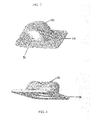
FIGURES 7-8 are perspective views of one of the secondary lenses of the apparatus ofFIGURE 1 , primarily illustrating the outer lens surface of the secondary lens. -
FIGURE 9 is a schematic perspective representation of a light pole mounting a lighting fixture including the inventive LED apparatus therein; the pole is positioned along the side of a roadway. -
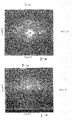
FIGURE 10 is a two-dimensional illumination intensity distribution of a lighting fixture such as inFIGURE 9 having lighting apparatus as described but without the shielding layer. It does not represent the invention, but is not prior art. -
FIGURE 11 is a two-dimensional illumination intensity distribution of a lighting fixture such as inFIGURE 9 having lighting apparatus as described with the shielding layer. -
FIGURES 1-4 and9 illustrate anLED apparatus 10 for illumination toward apreferential side 36 in adownward direction 48 andoutward direction 49.LED apparatus 10 includes a mountingboard 12,LED package 14 thereon withprimary lens 16 havingcentral axis 18, andsecondary lens member 20 overprimary lens 16 and establishinglight path 22 therebetween. The mountingboard 12 is connected to aheat sink 54 as shown inFIGURES 1 and 2 . One or more, typically several, LED packages 14 are arranged on a mountingboard 12 to form what is referred to as an LED module 58. One or more LED modules 58 are used as the light source for various innovative lighting fixtures. - As shown in
FIGURE 3 shield member 24, in the form of a layer, is positioned over mountingboard 12,LED package 14 andsecondary lens member 20.Shield member 24 hasshield portion 26 and a substantially planarnon-shield portion 28 thereabout as seen inFIGURE 6 .FIGURES 5 and6 illustrate thatshield member 24 has a shield-member aperture 30 aligned withlight path 22 andshield portion 26 borders shield-member aperture 30. - As shown in
FIGURES 7 and 8 ,secondary lens 20 includes alens portion 32 which is substantially transparent and aflange 34 portion thereabout.Lens portions 32 is adjacent toflange portion 34 as illustrated inFIGURES 7 and 8 .Shield portion 26 extends over a part oflens portion 32 ofsecondary lens member 20.Secondary lens member 20 is asymmetrical and has anillumination pattern 50 with apreferential side 36 and anon-preferential side 38 as shown inFIGURES 9-11 .Shield portion 26 is positioned to intercept light onnon-preferential side 38. - In
FIGURES 10 and 11 ,secondary lens 20 defines preferential side as indicated byreference number 36.FIGURES 10 and 11 also indicate, byreference number 38, the direction toward the opposite,non-preferential side 38. -
FIGURE 10 and 11 illustrate a two-dimensionalillumination intensity distribution 50 for an embodiment containing anLED package 14, a singleprimary lens 16 and a singlesecondary lens 20.Pattern 50 inFIGURES 10 and 11 was generated using optical ray-tracing software to simulate the illumination intensity emanating fromLED apparatus 10. - The brightness of
illumination pattern 50 inFIGURE 11 illustrates the relative intensity distribution using ashield member layer 24, demonstrating that a very large percentage of the light emanating fromapparatus 10 is redirected toward thepreferential side 36 byshield member layer 24 ofapparatus 10 and only a small amount of trespass light on thenon-preferential side 38.FIGURE 10 illustrates the relative intensity distribution without theshield member layer 24 present, demonstrating that light is not blocked from theapparatus 10 resulting in a large amount of trespass light on thenon-preferential side 38. -
FIGURES 1-4 illustrate thatcover 40 securesshield member 24 with respect tosecondary lens member 20,primary lens 16 andLED package 14.Cover 40 has anopening 42 aligned with thelight path 22 as shown inFIGURES 1-3 .Shield member 24 is sandwiched betweencover 40 andflange 34 ofsecondary lens member 20 - As illustrated in
FIGURE 6 whencover 40 is secured in place the sandwiching is of thenon-shield portion 28 ofshield member 24 and offlange 34 ofsecondary lens member 20. In certain embodiments,flange 34 ofsecondary lens member 20 is sandwiched against mountingboard 12. - In certain embodiments, as illustrated in
FIGURE 6 ,shield portion 26 ofshield member 24 has areflective surface 44 facingsecondary lens member 20. Another embodiment of theLED apparatus 10 is where an enclosure barrier member layer, such as a gasket 46, is sandwiched between theshield member 24 andsecondary lens member 20 as shown inFIGURE 3 . In yet another embodiment ofLED apparatus 10 is where analuminum layer 56 is sandwiched between the mountingboard 12 and thesecondary lens member 20 as seen inFIGURE 3 . -
LED apparatus 10 can consist of only oneLED package 14 on a mountingboard 12 with a correspondingprimary lens 16,secondary lens member 20 andshield member 24 or a plurality of LED packages 14 on a mountingboard 12 with correspondingprimary lenses 16,secondary lens members 20 andshield members 24. - In some embodiments, as shown in
FIGURE 3 , a plurality ofLED packages 14 are spaced from one another on the mountingboard 12. A plurality ofsecondary lens members 20 are also present in certain embodiments as illustrated inFIGURE 3 . Eachsecondary lens member 20 is positioned over theprimary lens 16 of acorresponding LED package 14. Each primary-lens/secondary-lens-member pair 52 establishes alight path 22 and has acentral axis 18 as shown inFIGURE 6 . A plurality ofshield portions 26 of theshield member 24 are also present in certain embodiments as illustrated inFIGURE 3 . As shown inFIGURES 3 and6 eachshield portion 26 is positioned partially over each primary-lens/secondary-lens-member pair 52 thereby to intercept a portion of thelight path 22 emitted from the correspondingLED package 14. - A wide variety of materials are available for the various parts discussed and illustrated herein. While the principles of this apparatus have been described in connection with specific embodiments, it should be understood clearly that these descriptions are made only by way of example and are not intended to limit the scope of the invention.
Claims (12)
- LED apparatus (10) including a mounting board (12), an LED package (14) on the mounting board (12) and having a primary lens (16), and a secondary lens member (20) aligned over the primary lens (16) and establishing a light path (22) therebetween, the secondary lens member (20) including a lens portion (32) and a flange (34) thereabout, wherein:a cover (40) has an opening (42) aligned with the light path (22) and securing the secondary lens member (20) over the LED package (14); anda resilient gasket member (46) is sandwiched between the cover (40) and the flange (34).
- The LED apparatus (10) of claim 1 further including a shield member (24) in the form of a layer positioned over the mounting board (12), the shield member (24) having a shield portion (26) and a substantially planar non-shield portion (28) thereabout, the shield member (24) also having a shield-member aperture (30) aligned with the light path (22) and the shield portion (26) bordering the shield-member aperture (30).
- The LED apparatus (10) of claim 2 wherein the shield portion (26) extends over a part of the lens portion (32) of the secondary lens member (20).
- The LED apparatus (10) of claims 2 or 3 wherein the shield member (24) is sandwiched between the cover (40) and the flange (34) of the secondary lens member (20).
- The LED apparatus (10) of any one of the preceding claims including a plurality of the LED packages (14) spaced-apart on the mounting board (12), and a plurality of the secondary lens members (20) each axially aligned over a respective one of the LED packages (14) and establishing the light path (22) therebetween.
- The LED apparatus (10) of claim 5 wherein the secondary lens members (20) are separate and discrete lens members each provided over a respective one of the LED packages (14).
- The LED apparatus (10) of claim 5 or 6 wherein the cover (40) has a plurality of openings each aligned with a corresponding one of the light paths (22) and securing each secondary lens member (20) over the respective LED package (14), and wherein the resilient gasket member (46) including a plurality of apertures therein, each aperture aligned with the corresponding one of the light paths (22).
- The LED apparatus (10) of claims 5, 6 or 7 wherein the resilient gasket member (46) is a unitary member.
- The LED apparatus (10) of any of the preceding claims wherein the resilient gasket (46) has an aperture sized to receive the lens portion (32).
- The LED apparatus (10) of claim 2, 3 or 4 wherein the shield member (24) is disposed between the secondary lens member(s) (20) and the cover (40).
- The LED apparatus (10) of claim 10 wherein the shield member (24) is between the cover (40) and the resilient gasket (46).
- The LED apparatus (10) of claim 2, 3, 4 or 10 wherein:the secondary lens member (20) is asymmetrical and has an illumination pattern with a preferential side (36) and a non-preferential side (38); andthe shield portion (26) is positioned to intercept light on the non-preferential side (38).
Applications Claiming Priority (2)
| Application Number | Priority Date | Filing Date | Title |
|---|---|---|---|
| US11/743,961 US8092042B2 (en) | 2007-05-03 | 2007-05-03 | Shield member in LED apparatus |
| EP08004710A EP1988576B1 (en) | 2007-05-03 | 2008-03-13 | Shield member in LED apparatus |
Related Parent Applications (2)
| Application Number | Title | Priority Date | Filing Date |
|---|---|---|---|
| EP08004710A Division EP1988576B1 (en) | 2007-05-03 | 2008-03-13 | Shield member in LED apparatus |
| EP08004710.3 Division | 2008-03-13 |
Publications (3)
| Publication Number | Publication Date |
|---|---|
| EP2543924A2 true EP2543924A2 (en) | 2013-01-09 |
| EP2543924A3 EP2543924A3 (en) | 2013-11-13 |
| EP2543924B1 EP2543924B1 (en) | 2015-11-04 |
Family
ID=39671627
Family Applications (2)
| Application Number | Title | Priority Date | Filing Date |
|---|---|---|---|
| EP08004710A Active EP1988576B1 (en) | 2007-05-03 | 2008-03-13 | Shield member in LED apparatus |
| EP12186829.3A Active EP2543924B1 (en) | 2007-05-03 | 2008-03-13 | LED apparatus |
Family Applications Before (1)
| Application Number | Title | Priority Date | Filing Date |
|---|---|---|---|
| EP08004710A Active EP1988576B1 (en) | 2007-05-03 | 2008-03-13 | Shield member in LED apparatus |
Country Status (10)
| Country | Link |
|---|---|
| US (1) | US8092042B2 (en) |
| EP (2) | EP1988576B1 (en) |
| CN (2) | CN104315413A (en) |
| AU (1) | AU2008201098B2 (en) |
| BR (1) | BRPI0810916A2 (en) |
| CA (1) | CA2622524C (en) |
| ES (1) | ES2405260T3 (en) |
| MX (1) | MX2008003491A (en) |
| NZ (1) | NZ566233A (en) |
| WO (1) | WO2008137171A1 (en) |
Families Citing this family (47)
| Publication number | Priority date | Publication date | Assignee | Title |
|---|---|---|---|---|
| US9212812B2 (en) | 2013-02-11 | 2015-12-15 | Cree, Inc. | LED light fixture with integrated light shielding |
| US7686469B2 (en) | 2006-09-30 | 2010-03-30 | Ruud Lighting, Inc. | LED lighting fixture |
| US9028087B2 (en) | 2006-09-30 | 2015-05-12 | Cree, Inc. | LED light fixture |
| US20090086491A1 (en) | 2007-09-28 | 2009-04-02 | Ruud Lighting, Inc. | Aerodynamic LED Floodlight Fixture |
| US9222632B2 (en) | 2013-01-31 | 2015-12-29 | Cree, Inc. | LED lighting fixture |
| US7976194B2 (en) * | 2007-05-04 | 2011-07-12 | Ruud Lighting, Inc. | Sealing and thermal accommodation arrangement in LED package/secondary lens structure |
| US7938558B2 (en) * | 2007-05-04 | 2011-05-10 | Ruud Lighting, Inc. | Safety accommodation arrangement in LED package/lens structure |
| US9666762B2 (en) * | 2007-10-31 | 2017-05-30 | Cree, Inc. | Multi-chip light emitter packages and related methods |
| US8449144B2 (en) | 2008-05-16 | 2013-05-28 | Musco Corporation | Apparatus, method, and system for highly controlled light distribution using multiple light sources |
| US8356916B2 (en) * | 2008-05-16 | 2013-01-22 | Musco Corporation | Method, system and apparatus for highly controlled light distribution from light fixture using multiple light sources (LEDS) |
| US7845829B2 (en) * | 2008-05-20 | 2010-12-07 | Abl Ip Holding Llc | Enclosures for LED circuit boards |
| CA2736395C (en) | 2008-09-15 | 2017-03-07 | Led Roadway Lighting Ltd. | Light emitting diode (led) roadway lighting fixture |
| DE102009021208A1 (en) * | 2009-05-13 | 2010-11-18 | Hella Kgaa Hueck & Co. | Lighting device for roads |
| US8622569B1 (en) | 2009-07-17 | 2014-01-07 | Musco Corporation | Method, system and apparatus for controlling light distribution using swivel-mount led light sources |
| US20110051413A1 (en) | 2009-08-25 | 2011-03-03 | Abl Ip Holding Llc | Optic shielding |
| US20110051410A1 (en) * | 2009-08-28 | 2011-03-03 | Chien Kuo Liang | In-wall led lamp can be adjustable in angles |
| US9303861B2 (en) * | 2009-09-14 | 2016-04-05 | Us Vaopto, Inc. | Light emitting diode light source modules |
| IT1397380B1 (en) * | 2010-01-08 | 2013-01-10 | Khatod Optoelectronic Srl | LIGHTING SYSTEM AND ASSEMBLY METHOD OF THE SAME. |
| CN102135239B (en) * | 2010-01-21 | 2013-01-23 | 财团法人工业技术研究院 | Illumination device and its optical element module |
| USD673307S1 (en) | 2011-05-12 | 2012-12-25 | Cooper Technologies Company | Light bar |
| USD674949S1 (en) * | 2011-11-03 | 2013-01-22 | Georgitsis Anthony C | Lighting system |
| US9151477B2 (en) | 2012-02-03 | 2015-10-06 | Cree, Inc. | Lighting device and method of installing light emitter |
| US9151457B2 (en) | 2012-02-03 | 2015-10-06 | Cree, Inc. | Lighting device and method of installing light emitter |
| US9310038B2 (en) | 2012-03-23 | 2016-04-12 | Cree, Inc. | LED fixture with integrated driver circuitry |
| US10054274B2 (en) | 2012-03-23 | 2018-08-21 | Cree, Inc. | Direct attach ceiling-mounted solid state downlights |
| US20140016318A1 (en) * | 2012-07-11 | 2014-01-16 | Stevan Pokrajac | LED Light Assembly |
| US8974077B2 (en) | 2012-07-30 | 2015-03-10 | Ultravision Technologies, Llc | Heat sink for LED light source |
| TW201407213A (en) * | 2012-08-01 | 2014-02-16 | 鴻海精密工業股份有限公司 | LED light guiding element, LED light source module and direct-lit LED TV |
| FR2998033A1 (en) * | 2012-11-09 | 2014-05-16 | Al Babtain France Sas | LED LIGHTING DEVICE WITH ANGLE DISCHARGE |
| CN103032766A (en) * | 2012-12-12 | 2013-04-10 | 京东方科技集团股份有限公司 | Backlight module and display device |
| US9435519B2 (en) | 2013-01-31 | 2016-09-06 | Cree, Inc. | Light-fixture support assembly |
| US9400087B2 (en) | 2013-03-12 | 2016-07-26 | Abl Ip Holding Llc | Externally mounted shield for LED luminaire |
| US9195281B2 (en) | 2013-12-31 | 2015-11-24 | Ultravision Technologies, Llc | System and method for a modular multi-panel display |
| US10030819B2 (en) | 2014-01-30 | 2018-07-24 | Cree, Inc. | LED lamp and heat sink |
| WO2016033320A1 (en) | 2014-08-28 | 2016-03-03 | Cooper Technologies Company | Lighting fixture |
| US9470394B2 (en) * | 2014-11-24 | 2016-10-18 | Cree, Inc. | LED light fixture including optical member with in-situ-formed gasket and method of manufacture |
| KR102518368B1 (en) * | 2016-04-06 | 2023-04-13 | 삼성전자주식회사 | Lighting apparatus |
| USD809166S1 (en) | 2016-08-04 | 2018-01-30 | Vision Motor Sports, Inc. | Headlight |
| USD798475S1 (en) | 2016-08-04 | 2017-09-26 | Vision Motor Sports, Inc. | Headlight |
| EP3690311B1 (en) * | 2017-09-28 | 2024-12-04 | Suzhou Opple Lighting Co., Ltd. | Lighting device |
| CN110553157B (en) * | 2018-05-30 | 2023-04-21 | 首尔半导体株式会社 | Light emitting module, window unit for light emitting module and street lamp |
| CN109560181B (en) * | 2018-11-16 | 2020-04-17 | 重庆秉为科技有限公司 | LED packaging structure |
| NL2023295B1 (en) * | 2019-06-12 | 2021-01-21 | Schreder Sa | Light emitting device with adaptable glare class |
| US11899202B2 (en) * | 2022-03-04 | 2024-02-13 | Abl Ip Holding Llc | Extreme cutoff beam control optics |
| US11746989B1 (en) * | 2022-03-04 | 2023-09-05 | Abl Ip Holding Llc | Extreme cutoff beam control optics |
| EP4239244A1 (en) * | 2022-03-04 | 2023-09-06 | ABL IP Holding LLC | Extreme cutoff beam control optics |
| US20250003575A1 (en) * | 2023-06-30 | 2025-01-02 | Korrus, Inc. | Lighting devices, light distribution-modifying elements, and methods |
Citations (4)
| Publication number | Priority date | Publication date | Assignee | Title |
|---|---|---|---|---|
| US6972439B1 (en) | 2004-05-27 | 2005-12-06 | Samsung Electro-Mechanics Co., Ltd. | Light emitting diode device |
| US7019334B2 (en) | 2003-06-13 | 2006-03-28 | Stanley Electric Co., Ltd. | LED lamp for light source of a headlamp |
| US20060158080A1 (en) | 2005-01-19 | 2006-07-20 | Nichia Corporation | Surface light emitting apparatus |
| US20060175626A1 (en) | 2005-02-07 | 2006-08-10 | Lumileds Lighting U.S., Llc | Beam shutter in LED package |
Family Cites Families (50)
| Publication number | Priority date | Publication date | Assignee | Title |
|---|---|---|---|---|
| US4254453A (en) | 1978-08-25 | 1981-03-03 | General Instrument Corporation | Alpha-numeric display array and method of manufacture |
| US4603496A (en) | 1985-02-04 | 1986-08-05 | Adaptive Micro Systems, Inc. | Electronic display with lens matrix |
| US4914731A (en) * | 1987-08-12 | 1990-04-03 | Chen Shen Yuan | Quickly formed light emitting diode display and a method for forming the same |
| JPH05183141A (en) | 1991-07-12 | 1993-07-23 | Fuji Xerox Co Ltd | Color image sensor |
| US5617131A (en) | 1993-10-28 | 1997-04-01 | Kyocera Corporation | Image device having a spacer with image arrays disposed in holes thereof |
| FR2712108B3 (en) | 1993-11-04 | 1995-10-27 | Adaptive Micro Systems Inc | Electronic display device comprising a plurality of display elements. |
| JP3232389B2 (en) * | 1994-12-30 | 2001-11-26 | タキロン株式会社 | Dot matrix light emitting display with shading louver |
| JP3405620B2 (en) | 1995-05-22 | 2003-05-12 | 松下電器産業株式会社 | Solid-state imaging device |
| US5984494A (en) | 1995-09-08 | 1999-11-16 | Jimmy G. Cook | Light shield for an illumination system |
| US5711890A (en) | 1996-03-11 | 1998-01-27 | Eastman Kodak Company | Method for forming cylindrical lens arrays for solid state imager |
| JPH10268800A (en) | 1997-03-21 | 1998-10-09 | Sony Corp | Display device |
| US6325524B1 (en) | 1999-01-29 | 2001-12-04 | Agilent Technologies, Inc. | Solid state based illumination source for a projection display |
| US6502956B1 (en) | 1999-03-25 | 2003-01-07 | Leotek Electronics Corporation | Light emitting diode lamp with individual LED lenses |
| KR100682563B1 (en) * | 1999-07-26 | 2007-02-15 | 라보 스피아 가부시키가이샤 | Bulk lens, light emitting body, lighting device and optical information system |
| JP4318007B2 (en) | 1999-10-07 | 2009-08-19 | 富士フイルム株式会社 | Solid-state image sensor |
| JP2001189443A (en) | 1999-12-28 | 2001-07-10 | Sony Corp | Solid-state imaging device and method of manufacturing the same |
| US6630736B1 (en) | 2000-07-27 | 2003-10-07 | National Semiconductor Corporation | Light barrier for light sensitive semiconductor devices |
| US20020122134A1 (en) * | 2001-03-05 | 2002-09-05 | Kalua Kevin A. | Video display array of sealed, modular units |
| US6635941B2 (en) | 2001-03-21 | 2003-10-21 | Canon Kabushiki Kaisha | Structure of semiconductor device with improved reliability |
| US6837605B2 (en) | 2001-11-28 | 2005-01-04 | Osram Opto Semiconductors Gmbh | Led illumination system |
| US20030147237A1 (en) * | 2002-02-01 | 2003-08-07 | Halasz Christopher Lee | Flashlight |
| ITTO20020142A1 (en) * | 2002-02-19 | 2003-08-19 | Fraen Corp Srl | INTEGRATED PROJECTION UNIT, IN PARTICULAR FOR THE PROJECTION OF E-OR IMAGES OF LUMINOUS BEAMS WITH PERFORMANCE GEOMETRY. |
| TW546853B (en) | 2002-05-01 | 2003-08-11 | Au Optronics Corp | Active type OLED and the fabrication method thereof |
| US6730940B1 (en) | 2002-10-29 | 2004-05-04 | Lumileds Lighting U.S., Llc | Enhanced brightness light emitting device spot emitter |
| US7008084B2 (en) * | 2003-01-03 | 2006-03-07 | Galli Robert D | Lighting head assembly with integrated heat sink |
| JP4047186B2 (en) | 2003-02-10 | 2008-02-13 | 株式会社小糸製作所 | Vehicle headlamp and optical unit |
| US7182480B2 (en) | 2003-03-05 | 2007-02-27 | Tir Systems Ltd. | System and method for manipulating illumination created by an array of light emitting devices |
| US7396141B2 (en) * | 2003-03-25 | 2008-07-08 | Chapman/Leonard Enterprises, Inc. | LED push rod flashlight |
| US7543953B2 (en) * | 2003-03-25 | 2009-06-09 | Chapman/Leonard Enterprises, Inc. | LED flashlight with switch actuated by turning a lens tube |
| JP4485151B2 (en) | 2003-05-30 | 2010-06-16 | パナソニック株式会社 | Solid-state imaging device manufacturing method and solid-state imaging device. |
| US7009213B2 (en) | 2003-07-31 | 2006-03-07 | Lumileds Lighting U.S., Llc | Light emitting devices with improved light extraction efficiency |
| US6876008B2 (en) | 2003-07-31 | 2005-04-05 | Lumileds Lighting U.S., Llc | Mount for semiconductor light emitting device |
| JP4140042B2 (en) * | 2003-09-17 | 2008-08-27 | スタンレー電気株式会社 | LED light source device using phosphor and vehicle headlamp using LED light source device |
| DE602004020906D1 (en) | 2003-09-19 | 2009-06-10 | Panasonic Corp | LIGHTING DEVICE |
| AU2004284713B2 (en) * | 2003-10-06 | 2007-11-15 | Signify Holding B.V. | Method and apparatus for light collection, distribution and zoom |
| US7281818B2 (en) | 2003-12-11 | 2007-10-16 | Dialight Corporation | Light reflector device for light emitting diode (LED) array |
| US7080932B2 (en) | 2004-01-26 | 2006-07-25 | Philips Lumileds Lighting Company, Llc | LED with an optical system to increase luminance by recycling emitted light |
| JP4330476B2 (en) | 2004-03-29 | 2009-09-16 | スタンレー電気株式会社 | Semiconductor light emitting device |
| US7102185B2 (en) | 2004-06-21 | 2006-09-05 | Eastman Kodak Company | Lightshield architecture for interline transfer image sensors |
| JP4806197B2 (en) | 2005-01-17 | 2011-11-02 | パナソニック株式会社 | Solid-state imaging device |
| US20060176686A1 (en) | 2005-02-09 | 2006-08-10 | Mcvicker Brian D | Submersible lighting device |
| US7008096B1 (en) * | 2005-02-23 | 2006-03-07 | Osram Sylvania Inc. | Colored headlamp |
| US7261451B2 (en) | 2005-02-23 | 2007-08-28 | Osram Sylvania Inc. | Colored headlamp |
| KR100674871B1 (en) * | 2005-06-01 | 2007-01-30 | 삼성전기주식회사 | Side emitting type LED package and manufacturing method thereof |
| KR101220204B1 (en) | 2005-12-28 | 2013-01-09 | 엘지디스플레이 주식회사 | Light Emitting Diodes back-light assembly and liquid crystal display device module using thereof |
| KR20070114548A (en) * | 2006-05-29 | 2007-12-04 | 엘지전자 주식회사 | Cooking device |
| US7938558B2 (en) * | 2007-05-04 | 2011-05-10 | Ruud Lighting, Inc. | Safety accommodation arrangement in LED package/lens structure |
| US7566147B2 (en) * | 2007-05-04 | 2009-07-28 | Ruud Lighting, Inc. | Multi-LED light fixture with secure arrangement for LED-array wiring |
| US7637630B2 (en) * | 2008-04-22 | 2009-12-29 | Ruud Lighting, Inc. | Integrated shield-gasket member in LED apparatus |
| CN101614365B (en) * | 2008-06-25 | 2012-05-16 | 富准精密工业(深圳)有限公司 | Light guide module and light-emitting diode lamp using light guide module |
-
2007
- 2007-05-03 US US11/743,961 patent/US8092042B2/en active Active
-
2008
- 2008-02-22 CA CA2622524A patent/CA2622524C/en active Active
- 2008-02-26 NZ NZ566233A patent/NZ566233A/en unknown
- 2008-03-07 AU AU2008201098A patent/AU2008201098B2/en active Active
- 2008-03-12 MX MX2008003491A patent/MX2008003491A/en active IP Right Grant
- 2008-03-13 EP EP08004710A patent/EP1988576B1/en active Active
- 2008-03-13 EP EP12186829.3A patent/EP2543924B1/en active Active
- 2008-03-13 ES ES08004710T patent/ES2405260T3/en active Active
- 2008-05-02 WO PCT/US2008/005854 patent/WO2008137171A1/en not_active Ceased
- 2008-05-02 CN CN201410564690.3A patent/CN104315413A/en active Pending
- 2008-05-02 CN CN200880014626.0A patent/CN101675292B/en active Active
- 2008-05-02 BR BRPI0810916-8A2A patent/BRPI0810916A2/en not_active IP Right Cessation
Patent Citations (4)
| Publication number | Priority date | Publication date | Assignee | Title |
|---|---|---|---|---|
| US7019334B2 (en) | 2003-06-13 | 2006-03-28 | Stanley Electric Co., Ltd. | LED lamp for light source of a headlamp |
| US6972439B1 (en) | 2004-05-27 | 2005-12-06 | Samsung Electro-Mechanics Co., Ltd. | Light emitting diode device |
| US20060158080A1 (en) | 2005-01-19 | 2006-07-20 | Nichia Corporation | Surface light emitting apparatus |
| US20060175626A1 (en) | 2005-02-07 | 2006-08-10 | Lumileds Lighting U.S., Llc | Beam shutter in LED package |
Also Published As
| Publication number | Publication date |
|---|---|
| AU2008201098A1 (en) | 2008-11-20 |
| EP1988576B1 (en) | 2013-03-06 |
| MX2008003491A (en) | 2009-02-26 |
| AU2008201098B2 (en) | 2013-09-12 |
| EP1988576A1 (en) | 2008-11-05 |
| CN101675292A (en) | 2010-03-17 |
| WO2008137171A1 (en) | 2008-11-13 |
| CA2622524A1 (en) | 2008-11-03 |
| CA2622524C (en) | 2015-07-21 |
| NZ566233A (en) | 2009-07-31 |
| CN104315413A (en) | 2015-01-28 |
| EP2543924A3 (en) | 2013-11-13 |
| CN101675292B (en) | 2014-11-26 |
| EP2543924B1 (en) | 2015-11-04 |
| BRPI0810916A2 (en) | 2014-10-29 |
| US8092042B2 (en) | 2012-01-10 |
| ES2405260T3 (en) | 2013-05-30 |
| US20080272380A1 (en) | 2008-11-06 |
Similar Documents
| Publication | Publication Date | Title |
|---|---|---|
| EP2543924B1 (en) | LED apparatus | |
| US7637630B2 (en) | Integrated shield-gasket member in LED apparatus | |
| EP2307791B1 (en) | Light-directing apparatus with protected reflector-shield and lighting fixture utilizing same | |
| US20110310619A1 (en) | Lens for led lamps | |
| WO2010119580A1 (en) | Light source module | |
| AU2011253178A1 (en) | LED luminaire light redirection shield | |
| CA3061393A1 (en) | Energy reduction optics | |
| US9791116B2 (en) | Modular light engine for variable light pattern | |
| EP3260767B1 (en) | Led bar lighting with uniform illumination | |
| US8403537B2 (en) | Lighting apparatus | |
| JP5505238B2 (en) | Reflector, LED module, and lighting fixture | |
| HK1140003A (en) | Shield member in led apparatus | |
| WO2024227613A1 (en) | Lighting arrangement | |
| AU2013205105B2 (en) | Light-directing apparatus with protected reflector-shield and lighting fixture utilizing same | |
| CN104654085A (en) | LED (Light-Emitting Diode) illumination equipment with baffle | |
| HK1109800B (en) | Lens for led lamps |
Legal Events
| Date | Code | Title | Description |
|---|---|---|---|
| PUAI | Public reference made under article 153(3) epc to a published international application that has entered the european phase |
Free format text: ORIGINAL CODE: 0009012 |
|
| AC | Divisional application: reference to earlier application |
Ref document number: 1988576 Country of ref document: EP Kind code of ref document: P |
|
| AK | Designated contracting states |
Kind code of ref document: A2 Designated state(s): AT BE BG CH CY CZ DE DK EE ES FI FR GB GR HR HU IE IS IT LI LT LU LV MC MT NL NO PL PT RO SE SI SK TR |
|
| RAP1 | Party data changed (applicant data changed or rights of an application transferred) |
Owner name: CREE, INC. |
|
| PUAL | Search report despatched |
Free format text: ORIGINAL CODE: 0009013 |
|
| AK | Designated contracting states |
Kind code of ref document: A3 Designated state(s): AT BE BG CH CY CZ DE DK EE ES FI FR GB GR HR HU IE IS IT LI LT LU LV MC MT NL NO PL PT RO SE SI SK TR |
|
| RIC1 | Information provided on ipc code assigned before grant |
Ipc: F21S 8/08 20060101AFI20131009BHEP Ipc: F21W 131/103 20060101ALN20131009BHEP Ipc: F21V 5/04 20060101ALI20131009BHEP Ipc: F21Y 101/02 20060101ALN20131009BHEP Ipc: G02B 17/08 20060101ALN20131009BHEP Ipc: F21V 11/16 20060101ALN20131009BHEP Ipc: F21V 13/02 20060101ALI20131009BHEP |
|
| 17P | Request for examination filed |
Effective date: 20140513 |
|
| RBV | Designated contracting states (corrected) |
Designated state(s): AT BE BG CH CY CZ DE DK EE ES FI FR GB GR HR HU IE IS IT LI LT LU LV MC MT NL NO PL PT RO SE SI SK TR |
|
| GRAP | Despatch of communication of intention to grant a patent |
Free format text: ORIGINAL CODE: EPIDOSNIGR1 |
|
| RIC1 | Information provided on ipc code assigned before grant |
Ipc: F21S 8/08 20060101AFI20150520BHEP Ipc: F21Y 101/02 20060101ALN20150520BHEP Ipc: G02B 19/00 20060101ALN20150520BHEP Ipc: F21V 13/02 20060101ALI20150520BHEP Ipc: F21V 11/16 20060101ALN20150520BHEP Ipc: F21V 5/04 20060101ALI20150520BHEP Ipc: G02B 17/08 20060101ALN20150520BHEP Ipc: F21W 131/103 20060101ALN20150520BHEP |
|
| INTG | Intention to grant announced |
Effective date: 20150619 |
|
| RIC1 | Information provided on ipc code assigned before grant |
Ipc: F21Y 101/02 20060101ALN20150608BHEP Ipc: G02B 19/00 20060101ALN20150608BHEP Ipc: F21V 11/16 20060101ALN20150608BHEP Ipc: F21S 8/08 20060101AFI20150608BHEP Ipc: F21W 131/103 20060101ALN20150608BHEP Ipc: F21V 5/04 20060101ALI20150608BHEP Ipc: G02B 17/08 20060101ALN20150608BHEP Ipc: F21V 13/02 20060101ALI20150608BHEP |
|
| GRAS | Grant fee paid |
Free format text: ORIGINAL CODE: EPIDOSNIGR3 |
|
| GRAA | (expected) grant |
Free format text: ORIGINAL CODE: 0009210 |
|
| AC | Divisional application: reference to earlier application |
Ref document number: 1988576 Country of ref document: EP Kind code of ref document: P |
|
| AK | Designated contracting states |
Kind code of ref document: B1 Designated state(s): AT BE BG CH CY CZ DE DK EE ES FI FR GB GR HR HU IE IS IT LI LT LU LV MC MT NL NO PL PT RO SE SI SK TR |
|
| REG | Reference to a national code |
Ref country code: GB Ref legal event code: FG4D |
|
| REG | Reference to a national code |
Ref country code: CH Ref legal event code: EP |
|
| REG | Reference to a national code |
Ref country code: AT Ref legal event code: REF Ref document number: 759462 Country of ref document: AT Kind code of ref document: T Effective date: 20151115 |
|
| REG | Reference to a national code |
Ref country code: IE Ref legal event code: FG4D |
|
| REG | Reference to a national code |
Ref country code: DE Ref legal event code: R096 Ref document number: 602008041062 Country of ref document: DE |
|
| REG | Reference to a national code |
Ref country code: NL Ref legal event code: MP Effective date: 20151104 |
|
| REG | Reference to a national code |
Ref country code: LT Ref legal event code: MG4D |
|
| REG | Reference to a national code |
Ref country code: AT Ref legal event code: MK05 Ref document number: 759462 Country of ref document: AT Kind code of ref document: T Effective date: 20151104 |
|
| PG25 | Lapsed in a contracting state [announced via postgrant information from national office to epo] |
Ref country code: IS Free format text: LAPSE BECAUSE OF FAILURE TO SUBMIT A TRANSLATION OF THE DESCRIPTION OR TO PAY THE FEE WITHIN THE PRESCRIBED TIME-LIMIT Effective date: 20160304 Ref country code: IT Free format text: LAPSE BECAUSE OF FAILURE TO SUBMIT A TRANSLATION OF THE DESCRIPTION OR TO PAY THE FEE WITHIN THE PRESCRIBED TIME-LIMIT Effective date: 20151104 Ref country code: ES Free format text: LAPSE BECAUSE OF FAILURE TO SUBMIT A TRANSLATION OF THE DESCRIPTION OR TO PAY THE FEE WITHIN THE PRESCRIBED TIME-LIMIT Effective date: 20151104 Ref country code: NL Free format text: LAPSE BECAUSE OF FAILURE TO SUBMIT A TRANSLATION OF THE DESCRIPTION OR TO PAY THE FEE WITHIN THE PRESCRIBED TIME-LIMIT Effective date: 20151104 Ref country code: HR Free format text: LAPSE BECAUSE OF FAILURE TO SUBMIT A TRANSLATION OF THE DESCRIPTION OR TO PAY THE FEE WITHIN THE PRESCRIBED TIME-LIMIT Effective date: 20151104 Ref country code: NO Free format text: LAPSE BECAUSE OF FAILURE TO SUBMIT A TRANSLATION OF THE DESCRIPTION OR TO PAY THE FEE WITHIN THE PRESCRIBED TIME-LIMIT Effective date: 20160204 Ref country code: LT Free format text: LAPSE BECAUSE OF FAILURE TO SUBMIT A TRANSLATION OF THE DESCRIPTION OR TO PAY THE FEE WITHIN THE PRESCRIBED TIME-LIMIT Effective date: 20151104 |
|
| PG25 | Lapsed in a contracting state [announced via postgrant information from national office to epo] |
Ref country code: PL Free format text: LAPSE BECAUSE OF FAILURE TO SUBMIT A TRANSLATION OF THE DESCRIPTION OR TO PAY THE FEE WITHIN THE PRESCRIBED TIME-LIMIT Effective date: 20151104 Ref country code: PT Free format text: LAPSE BECAUSE OF FAILURE TO SUBMIT A TRANSLATION OF THE DESCRIPTION OR TO PAY THE FEE WITHIN THE PRESCRIBED TIME-LIMIT Effective date: 20160304 Ref country code: SE Free format text: LAPSE BECAUSE OF FAILURE TO SUBMIT A TRANSLATION OF THE DESCRIPTION OR TO PAY THE FEE WITHIN THE PRESCRIBED TIME-LIMIT Effective date: 20151104 Ref country code: FI Free format text: LAPSE BECAUSE OF FAILURE TO SUBMIT A TRANSLATION OF THE DESCRIPTION OR TO PAY THE FEE WITHIN THE PRESCRIBED TIME-LIMIT Effective date: 20151104 Ref country code: AT Free format text: LAPSE BECAUSE OF FAILURE TO SUBMIT A TRANSLATION OF THE DESCRIPTION OR TO PAY THE FEE WITHIN THE PRESCRIBED TIME-LIMIT Effective date: 20151104 Ref country code: LV Free format text: LAPSE BECAUSE OF FAILURE TO SUBMIT A TRANSLATION OF THE DESCRIPTION OR TO PAY THE FEE WITHIN THE PRESCRIBED TIME-LIMIT Effective date: 20151104 Ref country code: GR Free format text: LAPSE BECAUSE OF FAILURE TO SUBMIT A TRANSLATION OF THE DESCRIPTION OR TO PAY THE FEE WITHIN THE PRESCRIBED TIME-LIMIT Effective date: 20160205 |
|
| PG25 | Lapsed in a contracting state [announced via postgrant information from national office to epo] |
Ref country code: CZ Free format text: LAPSE BECAUSE OF FAILURE TO SUBMIT A TRANSLATION OF THE DESCRIPTION OR TO PAY THE FEE WITHIN THE PRESCRIBED TIME-LIMIT Effective date: 20151104 |
|
| REG | Reference to a national code |
Ref country code: DE Ref legal event code: R097 Ref document number: 602008041062 Country of ref document: DE |
|
| PG25 | Lapsed in a contracting state [announced via postgrant information from national office to epo] |
Ref country code: BE Free format text: LAPSE BECAUSE OF NON-PAYMENT OF DUE FEES Effective date: 20160331 Ref country code: EE Free format text: LAPSE BECAUSE OF FAILURE TO SUBMIT A TRANSLATION OF THE DESCRIPTION OR TO PAY THE FEE WITHIN THE PRESCRIBED TIME-LIMIT Effective date: 20151104 Ref country code: DK Free format text: LAPSE BECAUSE OF FAILURE TO SUBMIT A TRANSLATION OF THE DESCRIPTION OR TO PAY THE FEE WITHIN THE PRESCRIBED TIME-LIMIT Effective date: 20151104 Ref country code: SK Free format text: LAPSE BECAUSE OF FAILURE TO SUBMIT A TRANSLATION OF THE DESCRIPTION OR TO PAY THE FEE WITHIN THE PRESCRIBED TIME-LIMIT Effective date: 20151104 Ref country code: RO Free format text: LAPSE BECAUSE OF FAILURE TO SUBMIT A TRANSLATION OF THE DESCRIPTION OR TO PAY THE FEE WITHIN THE PRESCRIBED TIME-LIMIT Effective date: 20151104 |
|
| PLBE | No opposition filed within time limit |
Free format text: ORIGINAL CODE: 0009261 |
|
| STAA | Information on the status of an ep patent application or granted ep patent |
Free format text: STATUS: NO OPPOSITION FILED WITHIN TIME LIMIT |
|
| 26N | No opposition filed |
Effective date: 20160805 |
|
| PG25 | Lapsed in a contracting state [announced via postgrant information from national office to epo] |
Ref country code: MC Free format text: LAPSE BECAUSE OF FAILURE TO SUBMIT A TRANSLATION OF THE DESCRIPTION OR TO PAY THE FEE WITHIN THE PRESCRIBED TIME-LIMIT Effective date: 20151104 Ref country code: LU Free format text: LAPSE BECAUSE OF FAILURE TO SUBMIT A TRANSLATION OF THE DESCRIPTION OR TO PAY THE FEE WITHIN THE PRESCRIBED TIME-LIMIT Effective date: 20160313 |
|
| REG | Reference to a national code |
Ref country code: CH Ref legal event code: PL |
|
| GBPC | Gb: european patent ceased through non-payment of renewal fee |
Effective date: 20160313 |
|
| PG25 | Lapsed in a contracting state [announced via postgrant information from national office to epo] |
Ref country code: SI Free format text: LAPSE BECAUSE OF FAILURE TO SUBMIT A TRANSLATION OF THE DESCRIPTION OR TO PAY THE FEE WITHIN THE PRESCRIBED TIME-LIMIT Effective date: 20151104 |
|
| REG | Reference to a national code |
Ref country code: IE Ref legal event code: MM4A |
|
| PG25 | Lapsed in a contracting state [announced via postgrant information from national office to epo] |
Ref country code: BE Free format text: LAPSE BECAUSE OF FAILURE TO SUBMIT A TRANSLATION OF THE DESCRIPTION OR TO PAY THE FEE WITHIN THE PRESCRIBED TIME-LIMIT Effective date: 20151104 |
|
| REG | Reference to a national code |
Ref country code: FR Ref legal event code: ST Effective date: 20161130 |
|
| PG25 | Lapsed in a contracting state [announced via postgrant information from national office to epo] |
Ref country code: CH Free format text: LAPSE BECAUSE OF NON-PAYMENT OF DUE FEES Effective date: 20160331 Ref country code: FR Free format text: LAPSE BECAUSE OF NON-PAYMENT OF DUE FEES Effective date: 20160331 Ref country code: IE Free format text: LAPSE BECAUSE OF NON-PAYMENT OF DUE FEES Effective date: 20160313 Ref country code: LI Free format text: LAPSE BECAUSE OF NON-PAYMENT OF DUE FEES Effective date: 20160331 Ref country code: GB Free format text: LAPSE BECAUSE OF NON-PAYMENT OF DUE FEES Effective date: 20160313 |
|
| PG25 | Lapsed in a contracting state [announced via postgrant information from national office to epo] |
Ref country code: MT Free format text: LAPSE BECAUSE OF FAILURE TO SUBMIT A TRANSLATION OF THE DESCRIPTION OR TO PAY THE FEE WITHIN THE PRESCRIBED TIME-LIMIT Effective date: 20151104 |
|
| PG25 | Lapsed in a contracting state [announced via postgrant information from national office to epo] |
Ref country code: CY Free format text: LAPSE BECAUSE OF FAILURE TO SUBMIT A TRANSLATION OF THE DESCRIPTION OR TO PAY THE FEE WITHIN THE PRESCRIBED TIME-LIMIT Effective date: 20151104 Ref country code: HU Free format text: LAPSE BECAUSE OF FAILURE TO SUBMIT A TRANSLATION OF THE DESCRIPTION OR TO PAY THE FEE WITHIN THE PRESCRIBED TIME-LIMIT; INVALID AB INITIO Effective date: 20080313 |
|
| PG25 | Lapsed in a contracting state [announced via postgrant information from national office to epo] |
Ref country code: MT Free format text: LAPSE BECAUSE OF FAILURE TO SUBMIT A TRANSLATION OF THE DESCRIPTION OR TO PAY THE FEE WITHIN THE PRESCRIBED TIME-LIMIT Effective date: 20160331 Ref country code: TR Free format text: LAPSE BECAUSE OF FAILURE TO SUBMIT A TRANSLATION OF THE DESCRIPTION OR TO PAY THE FEE WITHIN THE PRESCRIBED TIME-LIMIT Effective date: 20151104 |
|
| PG25 | Lapsed in a contracting state [announced via postgrant information from national office to epo] |
Ref country code: BG Free format text: LAPSE BECAUSE OF FAILURE TO SUBMIT A TRANSLATION OF THE DESCRIPTION OR TO PAY THE FEE WITHIN THE PRESCRIBED TIME-LIMIT Effective date: 20151104 |
|
| RIC2 | Information provided on ipc code assigned after grant |
Ipc: F21V 13/02 20060101ALI20150608BHEP Ipc: F21Y 101/02 20000101ALN20150608BHEP Ipc: F21W 131/103 20060101ALN20150608BHEP Ipc: G02B 17/08 20060101ALN20150608BHEP Ipc: G02B 19/00 20060101ALN20150608BHEP Ipc: F21V 11/16 20060101ALN20150608BHEP Ipc: F21V 5/04 20060101ALI20150608BHEP Ipc: F21S 8/08 20060101AFI20150608BHEP |
|
| REG | Reference to a national code |
Ref country code: DE Ref legal event code: R082 Ref document number: 602008041062 Country of ref document: DE Representative=s name: KROHER - STROBEL RECHTS- UND PATENTANWAELTE PA, DE Ref country code: DE Ref legal event code: R081 Ref document number: 602008041062 Country of ref document: DE Owner name: IDEAL INDUSTRIES LIGHTING LLC, SYCAMORE, US Free format text: FORMER OWNER: CREE, INC., DURHAM, N.C., US Ref country code: DE Ref legal event code: R082 Ref document number: 602008041062 Country of ref document: DE Representative=s name: KROHER STROBEL RECHTS- UND PATENTANWAELTE PART, DE |
|
| REG | Reference to a national code |
Ref country code: DE Ref legal event code: R081 Ref document number: 602008041062 Country of ref document: DE Owner name: CREE LIGHTING USA LLC (N.D.GES.D. STAATES DELA, US Free format text: FORMER OWNER: IDEAL INDUSTRIES LIGHTING LLC, SYCAMORE, IL, US |
|
| PGFP | Annual fee paid to national office [announced via postgrant information from national office to epo] |
Ref country code: DE Payment date: 20250327 Year of fee payment: 18 |