EP2543914B1 - Vorrichtung zum radialen Zusammendrücken einer elastischen Leitung für eine strömendes Medium - Google Patents
Vorrichtung zum radialen Zusammendrücken einer elastischen Leitung für eine strömendes Medium Download PDFInfo
- Publication number
- EP2543914B1 EP2543914B1 EP20110005463 EP11005463A EP2543914B1 EP 2543914 B1 EP2543914 B1 EP 2543914B1 EP 20110005463 EP20110005463 EP 20110005463 EP 11005463 A EP11005463 A EP 11005463A EP 2543914 B1 EP2543914 B1 EP 2543914B1
- Authority
- EP
- European Patent Office
- Prior art keywords
- electric motor
- pressure element
- insertion channel
- translation module
- control unit
- Prior art date
- Legal status (The legal status is an assumption and is not a legal conclusion. Google has not performed a legal analysis and makes no representation as to the accuracy of the status listed.)
- Active
Links
- 230000006835 compression Effects 0.000 title description 4
- 238000007906 compression Methods 0.000 title description 4
- 238000003780 insertion Methods 0.000 claims description 41
- 230000037431 insertion Effects 0.000 claims description 41
- 238000013519 translation Methods 0.000 claims description 30
- 238000006073 displacement reaction Methods 0.000 claims description 13
- 230000009467 reduction Effects 0.000 claims description 7
- 238000004146 energy storage Methods 0.000 claims description 5
- 230000002401 inhibitory effect Effects 0.000 claims 1
- 238000010079 rubber tapping Methods 0.000 claims 1
- 238000013461 design Methods 0.000 description 7
- 230000008901 benefit Effects 0.000 description 3
- 239000007788 liquid Substances 0.000 description 3
- 238000010586 diagram Methods 0.000 description 2
- 239000012530 fluid Substances 0.000 description 2
- 239000007789 gas Substances 0.000 description 2
- 238000012546 transfer Methods 0.000 description 2
- 230000007704 transition Effects 0.000 description 2
- 239000007864 aqueous solution Substances 0.000 description 1
- 230000005540 biological transmission Effects 0.000 description 1
- 239000003990 capacitor Substances 0.000 description 1
- 230000008859 change Effects 0.000 description 1
- 238000011109 contamination Methods 0.000 description 1
- 238000007598 dipping method Methods 0.000 description 1
- 238000005265 energy consumption Methods 0.000 description 1
- 238000005516 engineering process Methods 0.000 description 1
- 230000001747 exhibiting effect Effects 0.000 description 1
- 238000004519 manufacturing process Methods 0.000 description 1
- 238000005259 measurement Methods 0.000 description 1
- 230000007935 neutral effect Effects 0.000 description 1
- 239000003921 oil Substances 0.000 description 1
- 238000005070 sampling Methods 0.000 description 1
- 238000000926 separation method Methods 0.000 description 1
- XLYOFNOQVPJJNP-UHFFFAOYSA-N water Substances O XLYOFNOQVPJJNP-UHFFFAOYSA-N 0.000 description 1
Images


Classifications
-
- F—MECHANICAL ENGINEERING; LIGHTING; HEATING; WEAPONS; BLASTING
- F16—ENGINEERING ELEMENTS AND UNITS; GENERAL MEASURES FOR PRODUCING AND MAINTAINING EFFECTIVE FUNCTIONING OF MACHINES OR INSTALLATIONS; THERMAL INSULATION IN GENERAL
- F16K—VALVES; TAPS; COCKS; ACTUATING-FLOATS; DEVICES FOR VENTING OR AERATING
- F16K7/00—Diaphragm valves or cut-off apparatus, e.g. with a member deformed, but not moved bodily, to close the passage ; Pinch valves
- F16K7/02—Diaphragm valves or cut-off apparatus, e.g. with a member deformed, but not moved bodily, to close the passage ; Pinch valves with tubular diaphragm
- F16K7/04—Diaphragm valves or cut-off apparatus, e.g. with a member deformed, but not moved bodily, to close the passage ; Pinch valves with tubular diaphragm constrictable by external radial force
- F16K7/045—Diaphragm valves or cut-off apparatus, e.g. with a member deformed, but not moved bodily, to close the passage ; Pinch valves with tubular diaphragm constrictable by external radial force by electric or magnetic means
-
- F—MECHANICAL ENGINEERING; LIGHTING; HEATING; WEAPONS; BLASTING
- F16—ENGINEERING ELEMENTS AND UNITS; GENERAL MEASURES FOR PRODUCING AND MAINTAINING EFFECTIVE FUNCTIONING OF MACHINES OR INSTALLATIONS; THERMAL INSULATION IN GENERAL
- F16K—VALVES; TAPS; COCKS; ACTUATING-FLOATS; DEVICES FOR VENTING OR AERATING
- F16K31/00—Actuating devices; Operating means; Releasing devices
- F16K31/02—Actuating devices; Operating means; Releasing devices electric; magnetic
- F16K31/04—Actuating devices; Operating means; Releasing devices electric; magnetic using a motor
- F16K31/046—Actuating devices; Operating means; Releasing devices electric; magnetic using a motor with electric means, e.g. electric switches, to control the motor or to control a clutch between the valve and the motor
Definitions
- the invention relates to a device for radially compressing an elastic conduit for a flowing medium at a line location, with an insertion channel for inserting a power portion of the line, with a transversely slidable to the insertion pressure piece and a counterpart on the insertion channel the pressure piece counterpart, both in protrude the deposit channel, and with an actuator acting on the pressure piece to its displacement.
- the GB 2 274 326 A describes a corresponding device in which the elastic line is open in a base part on which an electromotive Drive unit is arranged, which presses the pressure piece on the counterpart via a translation module in the form of an eccentrically mounted cam.
- the EP 1 664 600 B1 describes a comparable device with an electric actuator, which presses a displaceable pressure piece through a side wall of an insertion channel to press the elastic line located there by means of the pressure piece and a counterpart.
- the EP 1 308 657 A2 as well as the JP 04 136 573 A describe a comparable device in which an elastic line is squeezed off via a pressure piece, which is moved by an electric motor via an intermediate translation module in the form of a screw gear.
- An otherwise known device of this type for interrupting the flow of a volume flow of the flowing medium also called Schlauchquetschventil interrupts the flow of the flowing medium by clamping an elastic tube.
- the actuator has an electromagnet whose armature is fixedly connected to the radially pressing on the hose pressure piece, and a pressure piece loading the pressure spring.
- the compression spring presses the pressure piece on the hose point, so that the hose is completely compressed. With energization of the electromagnet, the spring force of the compression spring is compensated, the pressure piece releases the tube and the elastic tube produces its original clear cross-section.
- the invention has for its object to achieve higher pressure forces in a device of the type mentioned in a compact design on the pressure piece.
- the insertion channel is in a base unit carrying the drive unit, this transversely, containing and the translation module is received in the base part, wherein the pressure piece connected to the output member of the translation module penetrates through a recess crossing the insertion channel in the channel wall of the insertion channel.
- the counterpart is removably inserted into a slot formed in the base part.
- the shaft is arranged opposite the recess for dipping through the pressure piece and traverses the insertion channel.
- the counterpart is manually operable and can be removed for insertion and removal of the line section in the insertion channel.
- the device according to the invention has the advantage that, as a result of the design of the actuator as an electromotive drive unit coupled to a translation module, significantly higher pressure forces for compressing the elastic line are achieved with respect to an electromagnet. With the higher pressure forces thicker-walled lines or lines can be reliably shut off with larger flow pressures.
- the current consumption of the electric motor drive unit is significantly lower than in the case of an electromagnet, in particular when the drive unit advantageously has a reduction gear. Unlike an electromagnet, the current consumption in the end positions of the pressure piece can be reduced without changing the clear line cross section set by the pressure piece at the line location. With the inventive design of the actuator, larger strokes of the pressure piece can be realized without additional energy consumption, so that lines with a large pressure gauge can be used.
- the translation module is self-locking and has a fixedly connected to the output shaft input member and a fixedly connected to the pressure piece output member, which is preferably designed in one piece with the pressure piece.
- Input and output member are arranged coaxially and each have one of two sliding on one another, increasing in the axial direction control contours.
- the increase of the control contours is advantageously chosen so that the translation module is self-locking. This has the advantage that upon reaching a desired displacement of the pressure piece, and thus a set flow cross-section in the line, the electric motor drive unit can be de-energized without the pressure piece changes its assumed position. This contributes significantly to energy savings.
- input and output member are formed as a hollow cylinder and formed the control contours as circumferential to the hollow cylinders annular surfaces.
- the hollow cylindrical input member is rotatably and axially in the hollow cylindrical output member slidably guided.
- a holder which partially surrounds the line section is designed for immovable fixing of the line section in the base part at both ends of the insertion channel.
- the clear diameter of the holder is advantageously smaller than the diameter of the insertion channel, so that the elastic line section can be clamped in the holders in a simple manner.
- the insertion channel and the two end holders have an approximately C-shaped cross-section and form a laterally open insertion opening for the line section.
- the base part is divided into a channel body containing the insertion channel and a drive unit bearing, provided with a radially projecting mounting flange flange body, which are firmly connected.
- the translation module is received in a cavity in the base part, which is composed of a cavity formed in the flange body and in the base part.
- the output member of the translation module on a first and a second axial stop, which limit the displacement of the pressure piece together with a first counter-stopper formed on the base part and formed on the input member of the translation module second counter-stop.
- the first axial stop of a flange protruding radially on the output element and the first counterstop of one in the base part, preferably on the channel body of the base are advantageous Base part, trained annular shoulder formed, wherein preferably the annular shoulder is realized in that the two cavity portions of the translational module receiving cavity are designed with different cross sections, so that at the transition from cross-section larger cavity portion in the flange to cross-section smaller cavity portion in the channel body, a cavity forming the annular shoulder.
- the second axial stop and the second counter-stop are each formed by an axial web limiting the control contours on the output and input member. In this way, stops and counter-attacks can be produced in terms of production technology while achieving a simple assembly.
- the pressure piece is formed strictlytig with rounded sword edge, and the counterpart has a sword blade facing, extending in the direction of the scabbard, finger-like, convex hump.
- the hump is on an approximately cuboid support body, preferably in one piece with this, arranged and the support body is guided in the shaft.
- the curves of the sword blade and the hump result in a gentle pressing of the elastic pipe. Damage to the pinch point of the line can be avoided, which to a long life of the line.
- the electromotive drive unit comprises a arranged in a connectable to a supply voltage circuit electric motor, for. B. in the form of a DC motor, and a z. B. gearbox designed as a reduction gear with an output shaft.
- a supply voltage circuit electric motor for. B. in the form of a DC motor
- a z. B. gearbox designed as a reduction gear with an output shaft.
- a measuring resistor for measuring current is arranged in the circuit of the electric motor.
- the measured variable measured at the measuring resistor is controlled by a z. B. electrical control unit, z. B. control electronics supplied.
- control signals applied to the control unit the volume flow of the medium through the line location is completely disconnected or more or less released.
- the control unit has a first control module which adjusts the pressure force required on the pressure piece as a function of the measured variable at the measuring resistor.
- a second control module of the control unit detects depending on the measured variable, the end of the adjustment of the pressure piece and triggers a shutdown of the electric motor or a reduction of its power consumption.
- a third control module of the control unit monitors the supply voltage and triggers the transfer of the pressure piece in a Verschiebeendlage in case of voltage drop.
- the circuit of the electric motor, a voltage divider for sensing the supply voltage and a Energy storage connected, which temporarily takes over the power supply of the electric motor in case of power failure.
- a bridge output stage is arranged in the circuit of the electric motor.
- the control unit has a fourth control module, which activates the bridge output stage, for reversing the direction of rotation of the electric motor.
- control unit is a microprocessor in which said control modules are integrated.
- a liquid or gaseous medium elastic conduit eg a hose
- a transverse to the insertion channel 11 displaceable pressure piece 12, one on the insertion channel 11 the pressure piece 12 opposite counterpart 13 and acting on the pressure piece 12 to its displacement actuator.
- the actuator comprises an electromotive drive unit 14 with an output shaft 15 and a translation module 16, which converts a rotational movement of the output shaft 15 into a linear movement of the pressure element 12.
- the translation module 16 has a fixedly connected to the output shaft 15 input member 17 and a fixedly connected to the pressure piece output member 18.
- the output member 18 and pressure piece 12 are made in one piece.
- Input member 17 and output member 18 are arranged coaxially and each have one of two successive sliding, increasing in the axial direction control contours 19 and 20, wherein the increase of the control contours 19, 20 is selected so that there is self-locking for the translation module 16.
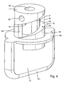
- Fig. 4 the translation module 16 with pressure piece 12 is shown in perspective in enlargement.
- input and output member 17, 18 are formed as a hollow cylinder.
- the hollow cylindrical input member 17 is rotatably guided in the hollow cylindrical output member 18 and axially displaceable.
- the control contours 19, 20 are formed as circumferential annular surfaces, annular surfaces 21 on the input member 17 and annular surface 22 on the output member 18.
- the input member 17 has a central axial bore 23 for pushing the input member 17 to the output shaft 15 and a radial bore 24 with internal thread for screwing a screw, not shown, through which the input member 17 is clamped to the output shaft 15.
- the integrally formed on the output member 18 pressure piece 12 is formed like a sword with rounded sword blade 121.
- a radially projecting flange 181 is integrally formed on the output member 18, which forms a first axial stop for limiting the displacement of the pressure piece 12.
- counterpart 13 shown in perspective has an approximately cuboid support body 25 with a finger-like, convex hump 26 which is integrally formed on the upper side of the support body 25.
- the support body 25 is provided on opposite longitudinal sides, each with a detent recess 27 for locking.
- a handle part for manual handling of the counterpart 13 may be formed on the support body 25 yet.
- the insertion channel 11 is formed in the base part 28.
- the base part 28 carries the electromotive drive unit 14 and receives the translation module 16, wherein the integrally connected to the output member 18 of the translation module 16 pressure member 12 passes through a insertion channel 11 transverse recess 29 in the channel wall of the insertion channel 11 and is guided in this displaceable.
- At the two ends of the insertion channel 11 each a the line section partially embracing holder 30 and 31 is formed for fixing the line section, wherein the clear diameter of the holder 30, 31 is smaller than the clear diameter of the insertion channel 11, so to cause a clamping of the line section in the base part 28.
- To form a transverse to the insertion channel 11 extending insertion opening for the line section have insertion channel 11 and holder 30, 31 has an approximately C-shaped cross-section.
- the base part 28 is subdivided into a channel body 32 containing the insertion channel 11 with holders 30, 31, and a flange body 33 carrying the electromotive drive unit 14, which is provided with a radially protruding fastening flange 331.
- Channel body 32 and flange 33 are by means of screws 34 ( Fig. 1 ) firmly connected.
- the flange body 33 is secured by means of screws 35 (FIG. Fig. 3 ) attached to the electric motor drive unit 14.
- the mounting flange 331 bears at the edge two recesses 36 for the insertion of fastening screws 37 (FIG. Fig. 3 ).
- the translation module 16 is arranged in a cavity 38 formed in the interior of the base part 28, which is composed of two cavity sections 381 and 382, of which the cavity section 381 is formed in the channel body 32 and the cavity section 382 is formed in the flange body 33.
- the cavity portion 381 is formed with a cross-section of the cavity portion 382 of smaller cross-section, so that at the transition of the two cavity sections 381, 382 a cavity stage with an annular shoulder 39 results, the first counter-stop to that of the flange 181 on the output member 18 of the translation module 16 formed first axial stop forms.
- a first axial stop and the first counter stop limit the displacement of the pressure element 12 towards the counterpart 13.
- a second axial stop on the output member 18 of the translation module 16 limited with a second counter-stop on the input member 17 of the translation module 16 the displacement of the pressure member 12 upwards, ie away from the counterpart 13th
- the second axial stop is of a on the output member 18, the control contour 20, so the annular surface 22, limiting axial ridge 40 and the second counter-stop formed by a control contour 19, so the annular surface 21, on the input member 17 limiting axial web 41 ( Fig. 4 ).
- the counterpart 13 is in the base member 28, more specifically in the channel body 32, the recess 29 for the pressure pad 12 on the insertion channel 11 opposite, a the insertion channel 11 crossing shaft 42 (FIG. Fig. 3 ) educated.
- the dimensions of shaft 42 and support body 25 of the counterpart 13 are coordinated so that the counterpart 13 is positively inserted into the slot 42, wherein the trained on the top of the support body 25, finger-like bumps 26 along the rounded blade blade 121 of the pressure element 12th extends and projects into the insertion channel 11.
- the counterpart 13 is locked in its inserted position in the shaft 42.
- the counterpart 13 in Fig. 3 be manually pulled out of the slot 42 to the left, if necessary, to easily remove an inserted in the insertion channel 11 line section or change.
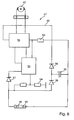
- the electric motor drive unit 14 comprises a connectable to a supply voltage electric motor 43, z.
- a supply voltage electric motor 43, z As a connectable to 12 V or 24 V DC direct current motor, and the output shaft 15 exhibiting gear 44, z. B. reduction gear, of which in Fig. 1 to 3 only motor housing 45 and gear housing 46 can be seen.
- the supply voltage is connected via a control unit 47, which has terminals 48 (+) and 49 (-) for this purpose.
- the control unit 47 is arranged on a base plate 28, more precisely on the flange body 33, mounted board 50 which extends along the electric motor drive unit 14 and is supported on the motor housing 45.
- the control unit 47 whose circuit diagram in Fig. 6 is shown, has a connected to the terminals 48, 49 circuit 60, in which the electric motor 43 is integrated via a bridge output stage 51, and a control unit 52, z.
- a measuring resistor 53 is also arranged for measuring current, the measured variable of the control unit 52 is supplied.
- a voltage divider 54 is connected for sampling the supply voltage, wherein the voltage tap of the voltage divider 54 of the control unit 52 is supplied.
- An energy storage 55 is placed on the one hand directly to the negative terminal 49 and on the other hand via a Verpolstoffdiode 56 to the positive terminal 48 to which the voltage divider 54 is connected.
- the control unit 52 is connected via a further polarity reversal protection diode 57 to the positive terminal 48 and is connected via control lines to the bridge output stage 51.
- a decoupling diode 58 is arranged in the circuit branch between the bridge circuit 51 and the connection point of energy storage 55 and polarity reversal protection diode 56 in the circuit branch between the bridge circuit 51 and the connection point of energy storage 55 and polarity reversal protection diode 56 .
- the control unit 52 has a plurality of control modules, which are combined in a microprocessor. With a first control module, the pressure force of the pressure piece 12 is set as a function of the measured variable delivered by the measuring resistor 53. A second control module detects, depending on the measured variable of the measuring resistor 53, the end of the displacement of the pressure piece 12 and triggers a shutdown of the electric motor 43 or at least a reduction in power consumption. A third control module triggers depending on theistssmaschinerabgriff the control unit 52 voltage supplied at voltage drop of the supply voltage, a transfer of the pressure pad 12 in a predetermined Verschiebeendlage.
- the connected to the circuit 60 of the electric motor 43 energy storage 55 which may be designed as a capacitor or a battery, takes over the short-term power supply of the electric motor 43 in case of failure of the supply voltage, so that it can be transferred to an end position.
- a fourth control module controls the bridge-end circuit 51 in order to reverse the direction of rotation of the electric motor 43.
Landscapes
- Engineering & Computer Science (AREA)
- General Engineering & Computer Science (AREA)
- Mechanical Engineering (AREA)
- Connection Of Motors, Electrical Generators, Mechanical Devices, And The Like (AREA)
Description
- Die Erfindung bezieht sich auf eine Vorrichtung zum radialen Zusammendrücken einer elastischen Leitung für ein strömendes Medium an einer Leitungsstelle, mit einem Einlegekanal zum Einlegen eines Leistungsabschnitts der Leitung, mit einem quer zum Einlegekanal verschieblichen Druckstück und einem am Einlegekanal dem Druckstück gegenüberliegenden Gegenstück, die beide in den Einlagekanal hineinragen, und mit einem auf das Druckstück zu dessen Verschiebung wirkenden Aktor.
- Mit einer solchen Vorrichtung wird durch Zusammendrücken oder Quetschen einer Leitungsstelle einer elastischen Leitung, z.B. eines Schlauchs, der durch die Leitung fließende Volumenstrom eines flüssigen oder gasförmigen Mediums, mitunter auch Fluid genannt, bis zur vollständigen Unterbrechung gedrosselt. Verwendete Fluide sind z. B. Wasser, wässrige Lösungen im Medizin- und Nahrungsmittelbereich, Öle, Luft, neutrale Gase.
- Die
GB 2 274 326 A - Die
EP 1 664 600 B1 beschreibt eine vergleichbare Vorrichtung mit einem elektrischen Aktor, der ein verschiebliches Druckstück durch eine Seitenwand eines Einlegekanals drückt, um die dort befindliche elastische Leitung mittels des Druckstückes sowie eines Gegenstückes abzudrücken. - Die
EP 1 308 657 A2 sowie dieJP 04 136 573 A - Eine ansonsten bekannte Vorrichtung dieser Art zur Unterbrechung des Durchflusses eines Volumenstroms des strömenden Mediums, auch Schlauchquetschventil genannt, unterbricht den Durchfluss des strömenden Mediums durch Abklemmen eines elastischen Schlauchs. Hierzu weist der Aktor einen Elektromagneten, dessen Magnetanker fest mit dem radial auf dem Schlauch drückenden Druckstück verbunden ist, und eine das Druckstück belastende Druckfeder auf. In einer Ausführung des Schlauchquetschventils als stromlos geschlossen presst die Druckfeder das Druckstück auf die Schlauchstelle, so dass der Schlauch vollständig zusammengedrückt ist. Mit Bestromung des Elektromagneten wird die Federkraft der Druckfeder kompensiert, das Druckstück gibt den Schlauch frei und der elastische Schlauch stellt seinen ursprünglichen lichten Querschnitt her.
- Der Erfindung liegt die Aufgabe zugrunde, bei einer Vorrichtung der eingangs genannten Art bei kompakter Ausführung am Druckstück höhere Druckkräfte zu erzielen.
- Die Aufgabe ist erfindungsgemäß durch die Merkmale im Anspruch 1 gelöst.
- Gemäß der Erfindung ist der Einlegekanal in einem die Antriebseinheit tragenden Basisteil, dieses quer durchlaufend, enthalten und das Translationsmodul ist im Basisteil aufgenommen, wobei das mit dem Ausgangsglied des Translationsmoduls verbundene Druckstück durch eine den Einlegekanal querende Ausnehmung in der Kanalwand des Einlegekanals hindurchtaucht. Durch diese Maßnahmen wird eine bauraumsparende, kompakte Ausführung der Vorrichtung erzielt.
- Gemäß der Erfindung ist das Gegenstück in einen im Basisteil ausgebildeten Schacht herausnehmbar eingesetzt. Der Schacht ist gegenüber der Ausnehmung zum Durchtauchen des Druckstücks angeordnet und quert den Einlegekanal. Das Gegenstück ist manuell bedienbar und kann zum Einlegen und Entnehmen des Leitungsabschnitts in den Einlegekanal entfernt werden.
- Die erfindungsgemäße Vorrichtung hat den Vorteil, dass durch die Ausbildung des Aktors als eine mit einem Translationsmodul gekoppelte elektromotorische Antriebseinheit gegenüber einem Elektromagneten deutlich höhere Druckkräfte zum Zusammenpressen der elastischen Leitung erzielt werden. Mit den höheren Druckkräften können dickwandigere Leitungen oder Leitungen mit größeren Strömungsdrücken zuverlässig abgesperrt werden. Dabei ist die Stromaufnahme der elektromotorischen Antriebseinheit deutlich geringer als bei einem Elektromagneten, insbesondere dann, wenn die Antriebseinheit vorteilhaft ein Untersetzungsgetriebe aufweist. Anders als bei einem Elektromagneten kann die Stromaufnahme in den Endlagen des Druckstücks reduziert werden, ohne dass der vom Druckstück an der Leitungsstelle eingestellte lichte Leitungsquerschnitt verändert wird. Mit der erfindungsgemäßen Ausbildung des Aktors können ohne zusätzlichen Energiebedarf größere Hübe des Druckstücks realisiert werden, so dass auch Leitungen mit großem Druckmesser verwendet werden können.
- Die grundsätzlichen Vorteile der Vorrichtung bleiben dabei vollständig erhalten, nämlich das Vermeiden von Turbulenzen oder Totvolumen bei der Unterbrechung des Volumenstroms, die Möglichkeit des Durchflusses des Mediums in beide Richtungen, eine lange Lebensdauer der Leitung durch sanften und konstanten Druck beim Klemmen, die Auswechselbarkeit der Leitung als einziger medienberührter Teil und somit Vermeidung von Kontaminierung bei Einsatz von unterschiedlichen Flüssigkeiten oder Gasen.
- Gemäß der Erfindung ist das Translationsmodul selbsthemmend und weist ein mit der Abtriebswelle fest verbundenes Eingangsglied und ein mit dem Druckstück fest verbundenes Ausgangsglied auf, das vorzugsweise einstückig mit dem Druckstück ausgeführt ist. Ein- und Ausgangsglied sind koaxial angeordnet und weisen jeweils eine von zwei aufeinander gleitenden, in Achsrichtung ansteigenden Steuerkonturen auf. Vorteilhaft ist dabei der Anstieg der Steuerkonturen so gewählt, dass das Translationsmodul selbsthemmend ist. Dies hat den Vorteil, dass bei Erreichen eines gewünschten Verschiebewegs des Druckstücks, und damit eines eingestellten Durchflussquerschnitts in der Leitung, die elektromotorische Antriebseinheit stromlos geschaltet werden kann, ohne dass das Druckstück seine eingenommene Position verändert. Dies trägt erheblich zur Energieeinsparung bei.
- Weitere besondere Erfindungsmerkmale sowie Ausgestaltungen des Erfindungsgegenstands ergeben sich aus den weiteren Ansprüchen und der nachfolgenden Beschreibung.
- Gemäß einer vorteilhaften Ausführungsform der Erfindung sind Ein- und Ausgangsglied hohlzylindrisch ausgebildet und die Steuerkonturen als an den Hohlzylindern umlaufende Ringflächen ausgebildet. Das hohlzylindrische Eingangsglied ist in dem hohlzylindrischen Ausgangsglied drehbeweglich und axial verschieblich geführt. Diese konstruktive Ausbildung ermöglicht eine besonders einfache und kostengünstige Ausführung des Translationsmoduls.
- Gemäß einer vorteilhaften Ausführungsform der Erfindung ist an beiden Enden des Einlegekanals jeweils ein den Leitungsabschnitt teilweise umgreifender Halter zum unverschieblichen Festlegen des Leitungsabschnitts im Basisteil ausgebildet. Vorteilhaft ist dabei der lichte Durchmesser der Halter kleiner als der Durchmesser des Einlegekanals, so dass der elastische Leitungsabschnitt in einfacher Weise in den Haltern geklemmt werden kann.
- Gemäß einer vorteilhaften Ausführungsform der Erfindung weisen der Einlegekanal und die beiden endseitigen Halter einen etwa C-förmigen Querschnitt auf und bilden eine seitlich offene Einlegeöffnung für den Leitungsabschnitt.
- Gemäß einer vorteilhaften Ausführungsform der Erfindung ist das Basisteil in einen den Einlegekanal enthaltenden Kanalkörper und einen die Antriebseinheit tragenden, mit einem radial abstehenden Befestigungsflansch versehenen Flanschkörper unterteilt, die fest miteinander verbunden sind. Das Translationsmodul ist in einem Hohlraum im Basisteil aufgenommen, der sich aus einem im Flanschkörper und einem im Basisteil ausgebildeten Hohlraumabschnitt zusammensetzt. Durch diese Trennung des Basisteils wird die Montage der Vorrichtung deutlich erleichtert.
- Gemäß einer vorteilhaften Ausführungsform der Erfindung weist das Ausgangsglied des Translationsmoduls einen ersten und einen zweiten Axialanschlag auf, die zusammen mit einem am Basisteil ausgebildeten ersten Gegenanschlag und einem am Eingangsglied des Translationsmoduls ausgebildeten zweiten Gegenanschlag den Verschiebeweg des Druckstücks begrenzen. Vorteilhaft ist dabei der erste Axialanschlag von einen am Ausgangsglied radial abstehenden Flansch und der erste Gegenanschlag von einer im Basisteil, vorzugsweise am Kanalkörper des Basisteils, ausgebildeten Ringschulter gebildet, wobei bevorzugt die Ringschulter dadurch realisiert wird, dass die beiden Hohlraumabschnitte des das Translationsmodul aufnehmenden Hohlraums mit unterschiedlichen Querschnitten ausgeführt sind, so dass am Übergang vom querschnittsgrößeren Hohlraumabschnitt im Flanschkörper zum querschnittskleineren Hohlraumabschnitt im Kanalkörper eine die Ringschulter bildende Hohlraumstufe entsteht. Der zweite Axialanschlag und der zweite Gegenanschlag sind jeweils von einem die Steuerkonturen an Aus- und Eingangsglied begrenzenden Axialsteg gebildet. Auf diese Weise lassen sich Anschläge und Gegenanschläge bei Erzielung einer einfachen Montage fertigungstechnisch günstig herstellen.
- Gemäß einer vorteilhaften Ausführungsform der Erfindung ist das Druckstück schwertartig mit gerundeter Schwertschneide ausgebildet, und das Gegenstück weist einen der Schwertschneide zugekehrten, sich in Richtung der Schwertscheide erstreckenden, fingerartigen, konvexen Höcker auf. Der Höcker ist auf einem etwa quaderförmigen Tragkörper, vorzugsweise einstückig mit diesem, angeordnet und der Tragkörper ist in dem Schacht geführt. Durch die Rundungen von Schwertschneide und Höcker wird ein sanftes Pressen der elastischen Leitung erzielt. Beschädigungen an der Quetschstelle der Leitung werden vermieden, was zu einer langen Lebensdauer der Leitung beträgt. Durch Vorsehen von Rastmulden an einander abgekehrten Seitenflächen des Trägerkörpers lässt sich eine vorteilhafte, leicht lösbare Verrastung des Gegenstücks im Schacht erzielen.
- Gemäß einer vorteilhaften Ausführungsform der Erfindung umfasst die elektromotorische Antriebseinheit einen in einem an eine Versorgungsspannung anschließbaren Stromkreis angeordneten Elektromotor, z. B. in Form eines Gleichstrommotors, und ein z. B. als Untersetzungsgetriebe ausgebildetes Getriebe mit einer Abtriebswelle. Durch eine entsprechende Auslegung des Drehzahlverhältnisses des Getriebes kann das zur Betätigung des Druckstücks erforderliche Drehmoment des Elektromotors so gewählt werden, z. B. größer oder kleiner, dass eine möglichst große Energieeinsparung erfolgt.
- Gemäß einer vorteilhaften Ausführungsform der Erfindung ist im Stromkreis des Elektromotors ein Messwiderstand zur Strommessung angeordnet. Die am Messwiderstand abgegriffene Messgröße wird einer den Elektromotor steuernden z. B. elektrischen Steuereinheit, z. B. Steuerelektronik, zugeführt. Nach Maßgabe von an die Steuereinheit angelegten Steuersignalen wird der Volumenstrom des Mediums durch die Leitungsstelle vollständig abgeklemmt oder mehr oder weniger freigegeben. Durch die dabei erfolgende Strommessung können mit entsprechender Steuerung diverse Funktionen zur Energieeinsparung herbeigeführt werden.
- Gemäß einer vorteilhaften Ausführungsform der Erfindung weist die Steuereinheit ein erstes Steuermodul auf, das die am Druckstück erforderliche Druckkraft abhängig von der Messgröße am Messwiderstand einstellt. Ein zweites Steuermodul der Steuereinheit erkennt abhängig von der Messgröße das Ende des Verstellwegs des Druckstücks und löst eine Abschaltung des Elektromotors oder eine Reduzierung dessen Stromaufnahme aus. Ein drittes Steuermodul der Steuereinheit überwacht die Versorgungsspannung und löst bei Spannungsabfall die Überführung des Druckstücks in eine Verschiebeendlage aus. Hierzu sind am Stromkreis des Elektromotors ein Spannungsteiler zum Abtasten der Versorgungsspannung und ein Energiespeicher, angeschlossen, der bei Spannungsausfall kurzzeitig die Stromversorgung des Elektromotors übernimmt.
- Gemäß einer vorteilhaften Ausführungsform der Erfindung ist im Stromkreis des Elektromotors eine Brückenendstufe angeordnet. Die Steuereinheit weist ein die Brückenendstufe ansteuerndes viertes Steuermodul zum Umkehr der Drehrichtung des Elektromotors auf. Durch die Umkehrung der Drehrichtung der elektrischen Antriebseinheit wird das Eingangsglied des Translationsmoduls hochgedreht, so dass die Elastizität der elastischen Leitung ausreicht, das Druckstück und das Ausgangsglied des Translationsmoduls hoch zu drücken und damit den lichten Querschnitt der Leitung für den vollen Volumenstrom wieder herzustellen. Damit entfallen zusätzliche Rückstellmittel für das Druckstück, zu deren Überwindung bei der Zustellung der Leitung höhere Verstellkräfte von der elektromotorischen Antriebseinheit aufgebracht werden müssten.
- Gemäß einer vorteilhaften Ausführungsform der Erfindung ist die Steuereinheit ein Mikroprozessor, in dem die genannten Steuermodule integriert sind.
- Die Erfindung ist nachfolgend anhand eines in den Zeichnungen dargestellten Ausführungsbeispiels näher erläutert. Es zeigen:
- Fig. 1
- eine perspektivische Ansicht einer Vorrichtung zum radialen Zusammenpressen einer elastischen Leitung,
- Fig. 2
- einen Längsschnitt der Vorrichtung in
Fig. 1 , und zwar längs der Linie A-A inFig. 3 , - Fig. 3
- einen Schnitt längs der Linie B - B in
Fig. 2 , - Fig. 4
- eine vergrößerte perspektivische Darstellung eines mit einem Druckstück verbundenen Translationsmoduls in der Vorrichtung gemäß
Fig. 1 bis 3 , - Fig. 5
- eine perspektivische Darstellung eines Gegenstücks in der Vorrichtung gemäß
Fig. 1 bis 3 , - Fig. 6
- einen Schaltplan eines Steuergeräts der Vorrichtung in
Fig. 1 bis 3 . - Die in
Fig. 1 perspektivisch und inFig. 2 und3 in zwei verschiedenen Schnitten dargestellte Vorrichtung zum radialen Zusammendrücken einer von einem flüssigen oder gasförmigen Medium durchströmbaren elastischen Leitung, z.B. eines Schlauchs, an einer definierten Leitungs- bzw. Schlauchstelle, kurz Schlauchquetschventil genannt, weist einen Einlegekanal 11 zum Einlegen eines Leitungsabschnitts der Leitung, ein quer zum Einlegekanal 11 verschiebliches Druckstück 12, ein am Einlegekanal 11 dem Druckstück 12 gegenüberliegendes Gegenstück 13 und einen auf das Druckstück 12 zu dessen Verschiebung wirkenden Aktor auf. Der Aktor umfasst eine elektromotorische Antriebseinheit 14 mit einer Abtriebswelle 15 und ein Translationsmodul 16, das eine Drehbewegung der Abtriebswelle 15 in eine Linearbewegung des Druckstücks 12 umsetzt. Das Translationsmodul 16 weist ein mit der Abtriebswelle 15 fest verbundenes Eingangsglied 17 und ein mit dem Druckstück fest verbundenes Ausgangsglied 18 auf. Im dargestellten Ausführungsbeispiel sind Ausgangsglied 18 und Druckstück 12 einstückig ausgeführt. Eingangsglied 17 und Ausgangsglied 18 sind koaxial angeordnet und weisen jeweils eine von zwei aufeinander gleitenden, in Achsrichtung ansteigenden Steuerkonturen 19 bzw. 20 auf, wobei der Anstieg der Steuerkonturen 19, 20 so gewählt ist, dass sich für das Translationsmodul 16 Selbsthemmung ergibt. - In
Fig. 4 ist das Translationsmodul 16 mit Druckstück 12 perspektivisch in Vergrößerung dargestellt. Wie dort zu sehen ist, sind Ein- und Ausgangsglied 17, 18 hohlzylindrisch ausgebildet. Das hohlzylindrische Eingangsglied 17 ist in dem hohlzylindrischen Ausgangsglied 18 drehbeweglich und axial verschieblich geführt. Die Steuerkonturen 19, 20 sind als umlaufende Ringflächen, Ringflächen 21 am Eingangsglied 17 und Ringfläche 22 am Ausgangsglied 18, ausgebildet. Das Eingangsglied 17 weist eine zentrale Axialbohrung 23 zum Aufschieben des Eingangsglieds 17 auf die Abtriebswelle 15 und eine Radialbohrung 24 mit Innengewinde zum Einschrauben einer nicht gezeigten Schraube auf, durch die das Eingangsglied 17 an der Abtriebswelle 15 festgeklemmt wird. Das einstückig an das Ausgangsglied 18 angeformte Druckstück 12 ist schwertartig mit gerundeter Schwertschneide 121 ausgebildet. Außerdem ist an dem Ausgangsglied 18 ein radial abstehender Flansch 181 angeformt, der einen ersten Axialanschlag zur Begrenzung des Verschiebewegs des Druckstücks 12 bildet. - Das in
Fig. 5 in vergrößerter Darstellung perspektivisch dargestellte Gegenstück 13 weist einen etwa quaderförmigen Tragkörper 25 mit einem fingerartigen, konvexen Höcker 26 auf, der einstückig auf der Oberseite des Tragkörpers 25 ausgeformt ist. Der Trägkörper 25 ist auf voneinander abgekehrten Längsseiten mit je einer Rastmulde 27 zum Verrasten versehen. Außerdem kann an den Tragkörper 25 noch ein Griffteil zur manuellen Handhabung des Gegenstücks 13 angeformt sein. - Der Einlegekanal 11 ist im Basisteil 28 geformt. Das Basisteil 28 trägt die elektromotorische Antriebseinheit 14 und nimmt das Translationsmodul 16 auf, wobei das einstückig mit dem Ausgangsglied 18 des Translationsmoduls 16 verbundene Druckstück 12 durch eine den Einlegekanal 11 querende Ausnehmung 29 in der Kanalwand des Einlegekanals 11 hindurchtaucht und in dieser verschieblich geführt ist. An den beiden Enden des Einlegekanals 11 ist jeweils ein den eingelegten Leitungsabschnitt teilweise umgreifender Halter 30 bzw. 31 zum Festlegen des Leitungsabschnitts ausgebildet, wobei der lichte Durchmesser der Halter 30, 31 kleiner ist als der lichte Durchmesser des Einlegekanals 11, um so eine Klemmung des Leitungsabschnitts im Basisteil 28 zu bewirken. Zur Bildung einer quer zum Einlegekanal 11 verlaufenden Einlegeöffnung für den Leitungsabschnitt weisen Einlegekanal 11 und Halter 30, 31 einen etwa C-förmigen Querschnitt auf.
- Das Basisteil 28 ist im Ausführungsbeispiel in einen den Einlegekanal 11 mit Halter 30, 31 enthaltenden Kanalkörper 32 und einen die elektromotorische Antriebseinheit 14 tragenden Flanschkörper 33, der mit einen radial abstehenden Befestigungsflansch 331 versehen ist, unterteilt. Kanalkörper 32 und Flanschkörper 33 sind mittels Schrauben 34 (
Fig. 1 ) fest miteinander verbunden. Der Flanschkörper 33 ist mittels Schrauben 35 (Fig. 3 ) an der elektromotorischen Antriebseinheit 14 befestigt. Der Befestigungsflansch 331 trägt randseitig zwei Aussparungen 36 zum Durchstecken von Befestigungsschrauben 37 (Fig. 3 ). - Das Translationsmodul 16 ist in einem im Innern des Basisteils 28 ausgebildeten Hohlraum 38 angeordnet, der sich aus zwei Hohlraumabschnitten 381 und 382 zusammensetzt, von denen der Hohlraumabschnitt 381 im Kanalkörper 32 und der Hohlraumabschnitt 382 im Flanschkörper 33 ausgebildet ist. Der Hohlraumabschnitt 381 ist mit einem gegenüber dem Querschnitt des Hohlraumabschnitts 382 kleinerem Querschnitt ausgebildet, so dass sich am Übergang der beiden Hohlraumabschnitte 381, 382 eine Hohlraumstufe mit einer Ringschulter 39 ergibt, die einen ersten Gegenanschlag zu dem von dem Flansch 181 am Ausgangsglied 18 des Translationsmoduls 16 gebildeten ersten Axialanschlag bildet. Erster Axialanschlag und erster Gegenanschlag begrenzen den Verschiebeweg des Druckstücks 12 hin zum Gegenstück 13. Ein zweiter Axialanschlag am Ausgangsglied 18 des Translationsmoduls 16 begrenzt mit einem zweiten Gegenanschlag am Eingangsglied 17 des Translationsmoduls 16 den Verschiebeweg des Druckstücks 12 nach oben, also weg vom Gegenstück 13. Der zweite Axialanschlag wird von einem am Ausgangsglied 18 die Steuerkontur 20, also die Ringfläche 22, begrenzenden Axialsteg 40 und der zweite Gegenanschlag von einem die Steuerkontur 19, also die Ringfläche 21, am Eingangsglied 17 begrenzenden Axialsteg 41 gebildet (
Fig. 4 ). - Zur Aufnahme des Gegenstücks 13 ist in das Basisteil 28, genauer gesagt in den Kanalkörper 32, der Ausnehmung 29 für das Druckstück 12 am Einlegekanal 11 gegenüberliegend, ein den Einlegekanal 11 querender Schacht 42 (
Fig. 3 ) ausgebildet. Die Abmessungen von Schacht 42 und Tragkörper 25 des Gegenstücks 13 sind so aufeinander abgestimmt, dass das Gegenstück 13 formschlüssig in den Schacht 42 einsetzbar ist, wobei der auf der Oberseite des Tragkörpers 25 ausgebildete, fingerartige Höcker 26 sich längs der abgerundeten Schwertschneide 121 des Druckstücks 12 erstreckt und in den Einlegekanal 11 hineinragt. Über die Rastmulde 27 im Tragkörper 25 (Fig. 5 ) wird das Gegenstück 13 in seiner eingesetzten Position im Schacht 42 verrastet. Mittels eines am Tragkörper 25 ausgebildeten, hier nicht dargestellten, Griffteils kann das Gegenstück 13 inFig. 3 nach links manuell aus dem Schacht 42 herausgezogen werden, um bedarfsweise einen im Einlegekanal 11 einliegenden Leitungsabschnitt mühelos entfernen oder wechseln zu können. - Bei der beschriebenen Vorrichtung zum Klemmen der elastischen Leitung umfasst die elektromotorische Antriebseinheit 14 einen an eine Versorgungsspannung anschließbaren Elektromotor 43 , z. B. einen an 12 V oder 24 V Gleichspannung anschließbaren Gleichstrommotor, und ein die Abtriebswelle 15 aufweisendes Getriebe 44, z. B. Untersetzungsgetriebe, von denen in
Fig. 1 bis 3 nur Motorgehäuse 45 und Getriebegehäuse 46 zu sehen sind. Der Anschluss der Versorgungsspannung erfolgt über ein Steuergerät 47, das hierzu Anschlussklemmen 48 (+) und 49 (-) aufweist. Das Steuergerät 47 ist auf einer am Basisteil 28, genauer gesagt am Flanschkörper 33, befestigten Platine 50 angeordnet, die sich längs der elektromotorischen Antriebseinheit 14 erstreckt und sich am Motorgehäuse 45 abstützt. - Das Steuergerät 47, dessen Schaltplan in
Fig. 6 dargestellt ist, weist einen an die Anschlussklemmen 48, 49 angeschlossenen Stromkreis 60, in den der Elektromotor 43 über eine Brückenendstufe 51 eingebunden ist, sowie eine Steuereinheit 52, z. B. Steuerelektronik, zur Steuerung des Elektromotors 43 in inversen Drehrichtungen auf. Im Stromkreis 60 ist ferner ein Messwiderstand 53 zur Strommessung angeordnet, dessen Messgröße der Steuereinheit 52 zugeführt ist. An dem Stromkreis 60 ist ein Spannungsteiler 54 zum Abtasten der Versorgungsspannung angeschlossen, wobei der Spannungsabgriff des Spannungsteilers 54 der Steuereinheit 52 zugeführt ist. Ein Energiespeicher 55 ist einerseits unmittelbar an die Minus-Anschlussklemme 49 und andererseits über eine Verpolschutzdiode 56 an die Plus-Anschlussklemme 48 gelegt, an der auch der Spannungsteiler 54 angeschlossen ist. Die Steuereinheit 52 ist über eine weitere Verpolschutzdiode 57 an die Plus-Anschlussklemme 48 gelegt und ist über Steuerleitungen mit der Brückenendstufe 51 verbunden. In dem Stromkreiszweig zwischen der Brückenschaltung 51 und dem Anschlusspunkt von Energiespeicher 55 und Verpolschutzdiode 56 ist noch eine Entkopplungsdiode 58 angeordnet. - Die Steuereinheit 52 weist mehrere Steuermodule auf, die in einem Mikroprozessor zusammengefasst sind. Mit einem ersten Steuermodul wird die Druckkraft des Druckstücks 12 abhängig von der vom Messwiderstand 53 gelieferten Messgröße eingestellt. Ein zweites Steuermodul erkennt, abhängig von der Messgröße des Messwiderstands 53, das Ende des Verstellwegs des Druckstücks 12 und löst eine Abschaltung des Elektromotors 43 oder zumindest eine Reduzierung der Stromaufnahme auf. Ein drittes Steuermodul löst abhängig von der vom Spannungsteilerabgriff der Steuereinheit 52 zugeführten Spannung bei Spannungsabfall der Versorgungsspannung ein Überführen des Druckstücks 12 in eine vorgegebene Verschiebeendlage aus. Der am Stromkreis 60 des Elektromotors 43 angeschlossene Energiespeicher 55, der als Kondensator oder als Akku ausgeführt sein kann, übernimmt bei Ausfall der Versorgungsspannung die kurzzeitige Stromversorgung des Elektromotors 43, so dass dieser in eine Endlage überführt werden kann. Schließlich steuert ein vierter Steuermodul die Brückenendschaltung 51 zwecks Drehrichtungsumkehr des Elektromotors 43.
Claims (13)
- Vorrichtung zum radialen Zusammendrücken einer elastischen Leitung für ein strömendes Medium an einer Leitungsstelle, mit einem Einlegekanal (11) zum Einlegen eines Leitungsabschnitts der Leitung, mit einem quer zum Einlegekanal (11) verschieblichen Druckstück (12) und einem am Einlegekanal (11) dem Druckstück (12) gegenüberliegenden Gegenstück (13), die beide in den Einlegekanal (11) hineinragen, und mit einem auf das Druckstück (12) zu dessen Verschiebung wirkenden Aktor, wobei der Aktor eine elektromotorische Antriebseinheit (14) mit einer Abtriebswelle (15) und ein eine Drehbewegung der Abtriebswelle (15) in eine Linearbewegung des Druckstücks (12) umsetzendes Translationsmodul (16) aufweist, der Einlegekanal (11) in einem die elektromotorische Antriebseinheit (14) tragenden Basisteil (28), dieses quer durchlaufend, enthalten ist und das Translationsmodul (16) im Basisteil (28) aufgenommen ist und das mit dem Translationsmodul (16) verbundene Druckstück (12) durch eine den Einlegekanal (11) querende Ausnehmung (29) in der Kanalwand des Einlegekanals (11) hindurchtaucht, und das Gegenstück (13) in einen im Basisteil (28) der Ausnehmung (29) gegenüberliegend ausgebildeten, den Einlegekanal (11) querenden Schacht (42) herausnehmbar eingesetzt ist, dadurch gekennzeichnet, dass das Translationsmodul (16) selbsthemmend ist und ein mit der Abtriebswelle (15) fest verbundenes Eingangsglied (17) und ein mit dem Druckstück (12) fest verbundenes Ausgangsglied (18) aufweist, und wobei Ein- und Ausgangsglied (17, 18) koaxial angeordnet sind und jeweils eine von zwei aufeinander gleitenden, in Achsrichtung ansteigenden Steuerkonturen (19, 20) aufweisen.
- Vorrichtung nach Anspruch 1, dadurch gekennzeichnet, dass das Ausgangsglied (18) mit dem Druckstück (12) einstückig ausgebildet ist.
- Vorrichtung nach Anspruch 1 oder 2, dadurch gekennzeichnet, dass das Ausgangsglied (18) des Translationsmoduls (16) einen ersten und zweiten Axialanschlag aufweist, die zusammen mit einem am Basisteil (28) ausgebildeten ersten Gegenanschlag und einem am Eingangsglied (17) des Translationsmoduls (16) ausgebildeten zweiten Gegenanschlag den Verschiebeweg des Druckstücks (12) begrenzen.
- Vorrichtung nach einem der Ansprüche 1 bis 3, dadurch gekennzeichnet, dass das Druckstück (12) schwertartig mit gerundeter Schwertschneide (121) ausgebildet ist und das Gegenstück (13) einen der Schwertschneide (121) zugekehrten, sich in Richtung der Schwertschneide (121) erstreckenden, fingerartigen, konvexen Höcker (26) aufweist.
- Vorrichtung nach Anspruch 4, dadurch gekennzeichnet, dass der Höcker (26) auf der Oberfläche eines etwa quaderförmigen Tragkörpers (25), vorzugsweise einstückig mit diesem, angeordnet ist, und der Tragkörper (25) in dem Schacht (42) geführt ist.
- Vorrichtung nach einem der Ansprüche 1 bis 5, dadurch gekennzeichnet, dass die elektromotorische Antriebseinheit (14) einen Elektromotor (43), z. B. Gleichstrommotor, der in einem an eine Versorgungsspannung anschließbaren Stromkreis (60) angeordnet ist, und ein die Abtriebswelle (15) aufweisendes Getriebe (44), z. B. Untersetzungsgetriebe, umfasst.
- Vorrichtung nach Anspruch 6, dadurch gekennzeichnet, dass im Stromkreis (60) des Elektromotors (43) ein Messwiderstand (53) zur Strommessung angeordnet ist und die am Messwiderstand (53) abgegriffene Messgröße einer den Elektromotor (43) steuernden Steuereinheit (52), z. B. Steuerelektronik, zugeführt wird.
- Vorrichtung nach Anspruch 7, dadurch gekennzeichnet, dass die Steuereinheit (52) ein erstes Steuermodul aufweist, das die Druckkraft des Druckstücks (12) abhängig von der Messgröße einstellt.
- Vorrichtung nach Anspruch 7 oder 8, dadurch gekennzeichnet, dass die Steuereinheit (52) ein zweites Steuermodul aufweist, das abhängig von der Messgröße das Ende des Verstellwegs des Druckstücks (12) erkennt und eine Abschaltung des Elektromotors (53) oder eine Reduzierung dessen Stromaufnahme auslöst.
- Vorrichtung nach einem der Ansprüche 7 bis 9, dadurch gekennzeichnet, dass an dem Stromkreis (60) des Elektromotors (53) ein Spannungsteiler (54) zum Abtasten der Versorgungsspannung angeschlossen ist und die Steuereinheit (52) ein drittes Steuermodul aufweist, dem die am Spannungsteiler (54) abgetastete Spannung zugeführt ist und das abhängig von einem Spannungsabfall der abgetasteten Spannung die Überführung des Druckstücks (12) in eine Verschiebeendlage auslöst.
- Vorrichtung nach Anspruch 10, dadurch gekennzeichnet, dass an dem Stromkreis (60) des Elektromotors (43) ein Energiespeicher (55) angeschlossen ist, der bei Ausfall der Versorgungsspannung kurzzeitig die Stromversorgung des Elektromotors (43) übernimmt.
- Vorrichtung nach einem der Ansprüche 7 bis 11, dadurch gekennzeichnet, dass im Stromkreis (60) des Elektromotors (43) eine Brückenendstufe (51) angeordnet ist und die Steuereinheit (52) ein die Brückenendstufe (51) ansteuerndes viertes Steuermodul zum Umkehren der Drehrichtung des Elektromotors (43) aufweist.
- Vorrichtung nach einem der Ansprüche 7 bis 12, dadurch gekennzeichnet, dass die Steuereinheit (52) als ein die Steuermodule zusammenfassender Mikroprozessor ausgebildet ist.
Priority Applications (2)
| Application Number | Priority Date | Filing Date | Title |
|---|---|---|---|
| EP20110005463 EP2543914B1 (de) | 2011-07-05 | 2011-07-05 | Vorrichtung zum radialen Zusammendrücken einer elastischen Leitung für eine strömendes Medium |
| US13/532,141 US9127773B2 (en) | 2011-07-05 | 2012-06-25 | Device for radially compressing an elastic line for a flowing medium |
Applications Claiming Priority (1)
| Application Number | Priority Date | Filing Date | Title |
|---|---|---|---|
| EP20110005463 EP2543914B1 (de) | 2011-07-05 | 2011-07-05 | Vorrichtung zum radialen Zusammendrücken einer elastischen Leitung für eine strömendes Medium |
Publications (2)
| Publication Number | Publication Date |
|---|---|
| EP2543914A1 EP2543914A1 (de) | 2013-01-09 |
| EP2543914B1 true EP2543914B1 (de) | 2015-04-22 |
Family
ID=45421050
Family Applications (1)
| Application Number | Title | Priority Date | Filing Date |
|---|---|---|---|
| EP20110005463 Active EP2543914B1 (de) | 2011-07-05 | 2011-07-05 | Vorrichtung zum radialen Zusammendrücken einer elastischen Leitung für eine strömendes Medium |
Country Status (2)
| Country | Link |
|---|---|
| US (1) | US9127773B2 (de) |
| EP (1) | EP2543914B1 (de) |
Cited By (1)
| Publication number | Priority date | Publication date | Assignee | Title |
|---|---|---|---|---|
| EP3781852B1 (de) * | 2018-04-19 | 2022-11-02 | DrM, Dr. Müller AG | Quetschvorrichtung |
Families Citing this family (5)
| Publication number | Priority date | Publication date | Assignee | Title |
|---|---|---|---|---|
| US10195418B2 (en) | 2014-10-10 | 2019-02-05 | Nxstage Medical, Inc. | Pinch clamp devices, methods, and systems |
| KR20180050666A (ko) * | 2015-09-15 | 2018-05-15 | 네스텍 소시에테아노님 | 음료 제조 기계 |
| US10578220B2 (en) | 2017-02-27 | 2020-03-03 | Bimba Manufacturing Company | Proportionally controlled pinch valves, systems and methods |
| KR102360588B1 (ko) * | 2017-05-15 | 2022-02-08 | 카텐 컨트롤스 리미티드 | 핀치 밸브 |
| US20230250883A1 (en) * | 2022-02-04 | 2023-08-10 | Terumo Bct, Inc. | Pinch Valve |
Family Cites Families (13)
| Publication number | Priority date | Publication date | Assignee | Title |
|---|---|---|---|---|
| US4303222A (en) * | 1980-02-06 | 1981-12-01 | Red Valve Company, Inc. | Pinch valve |
| US4436277A (en) * | 1981-08-10 | 1984-03-13 | Edward Robak | Torque pinch valve |
| DE3923837C1 (de) * | 1989-07-19 | 1990-10-18 | Fresenius Ag, 6380 Bad Homburg, De | |
| US5078362A (en) * | 1990-03-15 | 1992-01-07 | Abbott Laboratories | Spring-biased valve for use in a positive displacement volumetic pump |
| US5250195A (en) * | 1990-07-13 | 1993-10-05 | Isco, Inc. | Apparatus and method for supercritical fluid extraction |
| JPH04136573A (ja) * | 1990-09-25 | 1992-05-11 | Kanji Matsumoto | チューブラバルブ |
| US5521473A (en) * | 1992-07-29 | 1996-05-28 | Kabushiki Kaisha Tokai-Rika-Denki-Seisakusho | Apparatus for driving and controlling power window while prohibiting drive of the motor during an initial period |
| GB2274326A (en) * | 1993-01-18 | 1994-07-20 | Kodak Ltd | Pinch valve with adjustable reaction member |
| AU676262B2 (en) * | 1993-04-02 | 1997-03-06 | Aran Engineering Development Ltd. | A valve |
| DE20117946U1 (de) * | 2001-11-03 | 2003-03-13 | Mueller A & K Gmbh Co Kg | Absperrorgan für strömende Medien |
| US7104275B2 (en) * | 2002-04-01 | 2006-09-12 | Emerson Electric Co. | Pinch valve |
| US7011287B2 (en) * | 2004-03-19 | 2006-03-14 | The Gates Corporation | Motor vehicle pinch valve |
| CH701531A2 (de) * | 2009-07-31 | 2011-01-31 | Novicon Engineering Gmbh | Schlauchquetschventil. |
-
2011
- 2011-07-05 EP EP20110005463 patent/EP2543914B1/de active Active
-
2012
- 2012-06-25 US US13/532,141 patent/US9127773B2/en active Active
Cited By (1)
| Publication number | Priority date | Publication date | Assignee | Title |
|---|---|---|---|---|
| EP3781852B1 (de) * | 2018-04-19 | 2022-11-02 | DrM, Dr. Müller AG | Quetschvorrichtung |
Also Published As
| Publication number | Publication date |
|---|---|
| US9127773B2 (en) | 2015-09-08 |
| EP2543914A1 (de) | 2013-01-09 |
| US20130009079A1 (en) | 2013-01-10 |
Similar Documents
| Publication | Publication Date | Title |
|---|---|---|
| EP2543914B1 (de) | Vorrichtung zum radialen Zusammendrücken einer elastischen Leitung für eine strömendes Medium | |
| DE102007058411A1 (de) | Vorrichtung zur lösbaren Verbindung eines Sensors | |
| EP1820967A1 (de) | Schlauchkassette für eine peristaltische Pumpe | |
| DE1500418A1 (de) | Steuervorrichtung | |
| EP1926928A1 (de) | Anordnung zum verstellen eines ventils | |
| EP0190269B1 (de) | Spritzenpumpe | |
| DE202006018756U1 (de) | Elektromotorisch angetriebenes Ventil | |
| EP0239670B1 (de) | Motorgetriebene Maschine mit Drehmomenteinstellung, insbesondere elektrisches Handwerkzeug | |
| DE102018002359B4 (de) | Kniehebelspannvorrichtung, zur Verwendung im Karosseriebau der Kfz-Industrie, mit zusätzlichem Drehlager am Kniehebelgelenkelement | |
| DD291819A5 (de) | Schmierstoff-mengenbegrenzer | |
| DE102013012158A1 (de) | Quetschventil | |
| DE2711346B1 (de) | Elektronischer Druckschalter | |
| DE102004001268A1 (de) | Geberzylinder für Kupplungsausrücksysteme | |
| DE2117550C3 (de) | Schraubstock | |
| EP2487393B1 (de) | Klemmventil | |
| DE10191359B4 (de) | Medienpumpe | |
| DE102019126685B4 (de) | Schlauchventil für Getränkeautomaten | |
| DE102006050664A1 (de) | Betätigungsvorrichtung für ein Ventil | |
| WO2017186449A1 (de) | Elektromagnetventil sowie betriebsverfahren | |
| DE4141172B4 (de) | Vorrichtung zum Umstellen eines Ventilgliedes an einer Sanitärarmatur | |
| DE3234982C2 (de) | Einrichtung zum intermittierenden Zuführen von Metallband oder -drahtmaterial in Stanz-Biegemaschinen | |
| DE239801C (de) | ||
| AT230744B (de) | Vorrichtung zur Steuerung des Druckmittelein- und -auslasses von Servomotoren, insbesondere zum Ein- und Ausschalten der Trennkupplung von Kraftfahrzeugantrieben | |
| DE2605784C3 (de) | Elektrischer Stellantrieb | |
| DE1152861B (de) | Elektrohydraulische Fernverstelleinrichtung fuer hydraulische Getriebe und Pumpen |
Legal Events
| Date | Code | Title | Description |
|---|---|---|---|
| PUAI | Public reference made under article 153(3) epc to a published international application that has entered the european phase |
Free format text: ORIGINAL CODE: 0009012 |
|
| AK | Designated contracting states |
Kind code of ref document: A1 Designated state(s): AL AT BE BG CH CY CZ DE DK EE ES FI FR GB GR HR HU IE IS IT LI LT LU LV MC MK MT NL NO PL PT RO RS SE SI SK SM TR |
|
| AX | Request for extension of the european patent |
Extension state: BA ME |
|
| 17P | Request for examination filed |
Effective date: 20130703 |
|
| RBV | Designated contracting states (corrected) |
Designated state(s): AL AT BE BG CH CY CZ DE DK EE ES FI FR GB GR HR HU IE IS IT LI LT LU LV MC MK MT NL NO PL PT RO RS SE SI SK SM TR |
|
| 17Q | First examination report despatched |
Effective date: 20130903 |
|
| GRAP | Despatch of communication of intention to grant a patent |
Free format text: ORIGINAL CODE: EPIDOSNIGR1 |
|
| INTG | Intention to grant announced |
Effective date: 20141105 |
|
| GRAS | Grant fee paid |
Free format text: ORIGINAL CODE: EPIDOSNIGR3 |
|
| GRAA | (expected) grant |
Free format text: ORIGINAL CODE: 0009210 |
|
| AK | Designated contracting states |
Kind code of ref document: B1 Designated state(s): AL AT BE BG CH CY CZ DE DK EE ES FI FR GB GR HR HU IE IS IT LI LT LU LV MC MK MT NL NO PL PT RO RS SE SI SK SM TR |
|
| REG | Reference to a national code |
Ref country code: GB Ref legal event code: FG4D Free format text: NOT ENGLISH |
|
| REG | Reference to a national code |
Ref country code: CH Ref legal event code: EP |
|
| REG | Reference to a national code |
Ref country code: AT Ref legal event code: REF Ref document number: 723437 Country of ref document: AT Kind code of ref document: T Effective date: 20150515 |
|
| REG | Reference to a national code |
Ref country code: IE Ref legal event code: FG4D Free format text: LANGUAGE OF EP DOCUMENT: GERMAN |
|
| REG | Reference to a national code |
Ref country code: DE Ref legal event code: R096 Ref document number: 502011006628 Country of ref document: DE Effective date: 20150603 |
|
| REG | Reference to a national code |
Ref country code: NL Ref legal event code: VDEP Effective date: 20150422 |
|
| REG | Reference to a national code |
Ref country code: LT Ref legal event code: MG4D |
|
| PG25 | Lapsed in a contracting state [announced via postgrant information from national office to epo] |
Ref country code: NL Free format text: LAPSE BECAUSE OF FAILURE TO SUBMIT A TRANSLATION OF THE DESCRIPTION OR TO PAY THE FEE WITHIN THE PRESCRIBED TIME-LIMIT Effective date: 20150422 |
|
| PG25 | Lapsed in a contracting state [announced via postgrant information from national office to epo] |
Ref country code: FI Free format text: LAPSE BECAUSE OF FAILURE TO SUBMIT A TRANSLATION OF THE DESCRIPTION OR TO PAY THE FEE WITHIN THE PRESCRIBED TIME-LIMIT Effective date: 20150422 Ref country code: LT Free format text: LAPSE BECAUSE OF FAILURE TO SUBMIT A TRANSLATION OF THE DESCRIPTION OR TO PAY THE FEE WITHIN THE PRESCRIBED TIME-LIMIT Effective date: 20150422 Ref country code: ES Free format text: LAPSE BECAUSE OF FAILURE TO SUBMIT A TRANSLATION OF THE DESCRIPTION OR TO PAY THE FEE WITHIN THE PRESCRIBED TIME-LIMIT Effective date: 20150422 Ref country code: HR Free format text: LAPSE BECAUSE OF FAILURE TO SUBMIT A TRANSLATION OF THE DESCRIPTION OR TO PAY THE FEE WITHIN THE PRESCRIBED TIME-LIMIT Effective date: 20150422 Ref country code: NO Free format text: LAPSE BECAUSE OF FAILURE TO SUBMIT A TRANSLATION OF THE DESCRIPTION OR TO PAY THE FEE WITHIN THE PRESCRIBED TIME-LIMIT Effective date: 20150722 Ref country code: PT Free format text: LAPSE BECAUSE OF FAILURE TO SUBMIT A TRANSLATION OF THE DESCRIPTION OR TO PAY THE FEE WITHIN THE PRESCRIBED TIME-LIMIT Effective date: 20150824 |
|
| PG25 | Lapsed in a contracting state [announced via postgrant information from national office to epo] |
Ref country code: RS Free format text: LAPSE BECAUSE OF FAILURE TO SUBMIT A TRANSLATION OF THE DESCRIPTION OR TO PAY THE FEE WITHIN THE PRESCRIBED TIME-LIMIT Effective date: 20150422 Ref country code: IS Free format text: LAPSE BECAUSE OF FAILURE TO SUBMIT A TRANSLATION OF THE DESCRIPTION OR TO PAY THE FEE WITHIN THE PRESCRIBED TIME-LIMIT Effective date: 20150822 Ref country code: GR Free format text: LAPSE BECAUSE OF FAILURE TO SUBMIT A TRANSLATION OF THE DESCRIPTION OR TO PAY THE FEE WITHIN THE PRESCRIBED TIME-LIMIT Effective date: 20150723 Ref country code: LV Free format text: LAPSE BECAUSE OF FAILURE TO SUBMIT A TRANSLATION OF THE DESCRIPTION OR TO PAY THE FEE WITHIN THE PRESCRIBED TIME-LIMIT Effective date: 20150422 |
|
| REG | Reference to a national code |
Ref country code: DE Ref legal event code: R097 Ref document number: 502011006628 Country of ref document: DE |
|
| PG25 | Lapsed in a contracting state [announced via postgrant information from national office to epo] |
Ref country code: EE Free format text: LAPSE BECAUSE OF FAILURE TO SUBMIT A TRANSLATION OF THE DESCRIPTION OR TO PAY THE FEE WITHIN THE PRESCRIBED TIME-LIMIT Effective date: 20150422 Ref country code: DK Free format text: LAPSE BECAUSE OF FAILURE TO SUBMIT A TRANSLATION OF THE DESCRIPTION OR TO PAY THE FEE WITHIN THE PRESCRIBED TIME-LIMIT Effective date: 20150422 |
|
| PLBE | No opposition filed within time limit |
Free format text: ORIGINAL CODE: 0009261 |
|
| STAA | Information on the status of an ep patent application or granted ep patent |
Free format text: STATUS: NO OPPOSITION FILED WITHIN TIME LIMIT |
|
| PG25 | Lapsed in a contracting state [announced via postgrant information from national office to epo] |
Ref country code: PL Free format text: LAPSE BECAUSE OF FAILURE TO SUBMIT A TRANSLATION OF THE DESCRIPTION OR TO PAY THE FEE WITHIN THE PRESCRIBED TIME-LIMIT Effective date: 20150422 Ref country code: RO Free format text: LAPSE BECAUSE OF NON-PAYMENT OF DUE FEES Effective date: 20150422 Ref country code: SK Free format text: LAPSE BECAUSE OF FAILURE TO SUBMIT A TRANSLATION OF THE DESCRIPTION OR TO PAY THE FEE WITHIN THE PRESCRIBED TIME-LIMIT Effective date: 20150422 Ref country code: MC Free format text: LAPSE BECAUSE OF FAILURE TO SUBMIT A TRANSLATION OF THE DESCRIPTION OR TO PAY THE FEE WITHIN THE PRESCRIBED TIME-LIMIT Effective date: 20150422 Ref country code: CZ Free format text: LAPSE BECAUSE OF FAILURE TO SUBMIT A TRANSLATION OF THE DESCRIPTION OR TO PAY THE FEE WITHIN THE PRESCRIBED TIME-LIMIT Effective date: 20150422 |
|
| REG | Reference to a national code |
Ref country code: CH Ref legal event code: PL |
|
| GBPC | Gb: european patent ceased through non-payment of renewal fee |
Effective date: 20150722 |
|
| 26N | No opposition filed |
Effective date: 20160125 |
|
| PG25 | Lapsed in a contracting state [announced via postgrant information from national office to epo] |
Ref country code: LU Free format text: LAPSE BECAUSE OF FAILURE TO SUBMIT A TRANSLATION OF THE DESCRIPTION OR TO PAY THE FEE WITHIN THE PRESCRIBED TIME-LIMIT Effective date: 20150705 |
|
| REG | Reference to a national code |
Ref country code: IE Ref legal event code: MM4A |
|
| PG25 | Lapsed in a contracting state [announced via postgrant information from national office to epo] |
Ref country code: CH Free format text: LAPSE BECAUSE OF NON-PAYMENT OF DUE FEES Effective date: 20150731 Ref country code: LI Free format text: LAPSE BECAUSE OF NON-PAYMENT OF DUE FEES Effective date: 20150731 Ref country code: GB Free format text: LAPSE BECAUSE OF NON-PAYMENT OF DUE FEES Effective date: 20150722 Ref country code: IT Free format text: LAPSE BECAUSE OF FAILURE TO SUBMIT A TRANSLATION OF THE DESCRIPTION OR TO PAY THE FEE WITHIN THE PRESCRIBED TIME-LIMIT Effective date: 20150422 |
|
| PG25 | Lapsed in a contracting state [announced via postgrant information from national office to epo] |
Ref country code: SI Free format text: LAPSE BECAUSE OF FAILURE TO SUBMIT A TRANSLATION OF THE DESCRIPTION OR TO PAY THE FEE WITHIN THE PRESCRIBED TIME-LIMIT Effective date: 20150422 |
|
| REG | Reference to a national code |
Ref country code: FR Ref legal event code: PLFP Year of fee payment: 6 |
|
| PG25 | Lapsed in a contracting state [announced via postgrant information from national office to epo] |
Ref country code: IE Free format text: LAPSE BECAUSE OF NON-PAYMENT OF DUE FEES Effective date: 20150705 |
|
| PG25 | Lapsed in a contracting state [announced via postgrant information from national office to epo] |
Ref country code: MT Free format text: LAPSE BECAUSE OF FAILURE TO SUBMIT A TRANSLATION OF THE DESCRIPTION OR TO PAY THE FEE WITHIN THE PRESCRIBED TIME-LIMIT Effective date: 20150422 |
|
| PG25 | Lapsed in a contracting state [announced via postgrant information from national office to epo] |
Ref country code: HU Free format text: LAPSE BECAUSE OF FAILURE TO SUBMIT A TRANSLATION OF THE DESCRIPTION OR TO PAY THE FEE WITHIN THE PRESCRIBED TIME-LIMIT; INVALID AB INITIO Effective date: 20110705 Ref country code: SM Free format text: LAPSE BECAUSE OF FAILURE TO SUBMIT A TRANSLATION OF THE DESCRIPTION OR TO PAY THE FEE WITHIN THE PRESCRIBED TIME-LIMIT Effective date: 20150422 Ref country code: BG Free format text: LAPSE BECAUSE OF FAILURE TO SUBMIT A TRANSLATION OF THE DESCRIPTION OR TO PAY THE FEE WITHIN THE PRESCRIBED TIME-LIMIT Effective date: 20150422 |
|
| PG25 | Lapsed in a contracting state [announced via postgrant information from national office to epo] |
Ref country code: SE Free format text: LAPSE BECAUSE OF FAILURE TO SUBMIT A TRANSLATION OF THE DESCRIPTION OR TO PAY THE FEE WITHIN THE PRESCRIBED TIME-LIMIT Effective date: 20150422 Ref country code: CY Free format text: LAPSE BECAUSE OF FAILURE TO SUBMIT A TRANSLATION OF THE DESCRIPTION OR TO PAY THE FEE WITHIN THE PRESCRIBED TIME-LIMIT Effective date: 20150422 |
|
| REG | Reference to a national code |
Ref country code: FR Ref legal event code: PLFP Year of fee payment: 7 |
|
| PG25 | Lapsed in a contracting state [announced via postgrant information from national office to epo] |
Ref country code: BE Free format text: LAPSE BECAUSE OF NON-PAYMENT OF DUE FEES Effective date: 20150731 |
|
| PG25 | Lapsed in a contracting state [announced via postgrant information from national office to epo] |
Ref country code: TR Free format text: LAPSE BECAUSE OF FAILURE TO SUBMIT A TRANSLATION OF THE DESCRIPTION OR TO PAY THE FEE WITHIN THE PRESCRIBED TIME-LIMIT Effective date: 20150422 |
|
| REG | Reference to a national code |
Ref country code: AT Ref legal event code: MM01 Ref document number: 723437 Country of ref document: AT Kind code of ref document: T Effective date: 20160705 |
|
| PG25 | Lapsed in a contracting state [announced via postgrant information from national office to epo] |
Ref country code: AT Free format text: LAPSE BECAUSE OF NON-PAYMENT OF DUE FEES Effective date: 20160705 |
|
| PG25 | Lapsed in a contracting state [announced via postgrant information from national office to epo] |
Ref country code: MK Free format text: LAPSE BECAUSE OF FAILURE TO SUBMIT A TRANSLATION OF THE DESCRIPTION OR TO PAY THE FEE WITHIN THE PRESCRIBED TIME-LIMIT Effective date: 20150422 |
|
| REG | Reference to a national code |
Ref country code: FR Ref legal event code: PLFP Year of fee payment: 8 |
|
| PG25 | Lapsed in a contracting state [announced via postgrant information from national office to epo] |
Ref country code: AL Free format text: LAPSE BECAUSE OF FAILURE TO SUBMIT A TRANSLATION OF THE DESCRIPTION OR TO PAY THE FEE WITHIN THE PRESCRIBED TIME-LIMIT Effective date: 20150422 |
|
| PGFP | Annual fee paid to national office [announced via postgrant information from national office to epo] |
Ref country code: FR Payment date: 20230621 Year of fee payment: 13 |
|
| PGFP | Annual fee paid to national office [announced via postgrant information from national office to epo] |
Ref country code: DE Payment date: 20230620 Year of fee payment: 13 |