EP2543905A1 - Brake assembly having a mounting clip - Google Patents
Brake assembly having a mounting clip Download PDFInfo
- Publication number
- EP2543905A1 EP2543905A1 EP12172443A EP12172443A EP2543905A1 EP 2543905 A1 EP2543905 A1 EP 2543905A1 EP 12172443 A EP12172443 A EP 12172443A EP 12172443 A EP12172443 A EP 12172443A EP 2543905 A1 EP2543905 A1 EP 2543905A1
- Authority
- EP
- European Patent Office
- Prior art keywords
- disposed
- arm
- mounting
- tooth
- mounting boss
- Prior art date
- Legal status (The legal status is an assumption and is not a legal conclusion. Google has not performed a legal analysis and makes no representation as to the accuracy of the status listed.)
- Granted
Links
Images


Classifications
-
- F—MECHANICAL ENGINEERING; LIGHTING; HEATING; WEAPONS; BLASTING
- F16—ENGINEERING ELEMENTS AND UNITS; GENERAL MEASURES FOR PRODUCING AND MAINTAINING EFFECTIVE FUNCTIONING OF MACHINES OR INSTALLATIONS; THERMAL INSULATION IN GENERAL
- F16D—COUPLINGS FOR TRANSMITTING ROTATION; CLUTCHES; BRAKES
- F16D65/00—Parts or details
- F16D65/02—Braking members; Mounting thereof
- F16D65/12—Discs; Drums for disc brakes
-
- F—MECHANICAL ENGINEERING; LIGHTING; HEATING; WEAPONS; BLASTING
- F16—ENGINEERING ELEMENTS AND UNITS; GENERAL MEASURES FOR PRODUCING AND MAINTAINING EFFECTIVE FUNCTIONING OF MACHINES OR INSTALLATIONS; THERMAL INSULATION IN GENERAL
- F16D—COUPLINGS FOR TRANSMITTING ROTATION; CLUTCHES; BRAKES
- F16D65/00—Parts or details
- F16D65/02—Braking members; Mounting thereof
- F16D65/12—Discs; Drums for disc brakes
- F16D65/123—Discs; Drums for disc brakes comprising an annular disc secured to a hub member; Discs characterised by means for mounting
-
- F—MECHANICAL ENGINEERING; LIGHTING; HEATING; WEAPONS; BLASTING
- F16—ENGINEERING ELEMENTS AND UNITS; GENERAL MEASURES FOR PRODUCING AND MAINTAINING EFFECTIVE FUNCTIONING OF MACHINES OR INSTALLATIONS; THERMAL INSULATION IN GENERAL
- F16D—COUPLINGS FOR TRANSMITTING ROTATION; CLUTCHES; BRAKES
- F16D65/00—Parts or details
- F16D65/02—Braking members; Mounting thereof
- F16D2065/13—Parts or details of discs or drums
- F16D2065/1304—Structure
- F16D2065/1316—Structure radially segmented
-
- F—MECHANICAL ENGINEERING; LIGHTING; HEATING; WEAPONS; BLASTING
- F16—ENGINEERING ELEMENTS AND UNITS; GENERAL MEASURES FOR PRODUCING AND MAINTAINING EFFECTIVE FUNCTIONING OF MACHINES OR INSTALLATIONS; THERMAL INSULATION IN GENERAL
- F16D—COUPLINGS FOR TRANSMITTING ROTATION; CLUTCHES; BRAKES
- F16D65/00—Parts or details
- F16D65/02—Braking members; Mounting thereof
- F16D2065/13—Parts or details of discs or drums
- F16D2065/1304—Structure
- F16D2065/1328—Structure internal cavities, e.g. cooling channels
-
- F—MECHANICAL ENGINEERING; LIGHTING; HEATING; WEAPONS; BLASTING
- F16—ENGINEERING ELEMENTS AND UNITS; GENERAL MEASURES FOR PRODUCING AND MAINTAINING EFFECTIVE FUNCTIONING OF MACHINES OR INSTALLATIONS; THERMAL INSULATION IN GENERAL
- F16D—COUPLINGS FOR TRANSMITTING ROTATION; CLUTCHES; BRAKES
- F16D65/00—Parts or details
- F16D65/02—Braking members; Mounting thereof
- F16D2065/13—Parts or details of discs or drums
- F16D2065/134—Connection
- F16D2065/1356—Connection interlocking
- F16D2065/1364—Connection interlocking with relative movement axially
-
- F—MECHANICAL ENGINEERING; LIGHTING; HEATING; WEAPONS; BLASTING
- F16—ENGINEERING ELEMENTS AND UNITS; GENERAL MEASURES FOR PRODUCING AND MAINTAINING EFFECTIVE FUNCTIONING OF MACHINES OR INSTALLATIONS; THERMAL INSULATION IN GENERAL
- F16D—COUPLINGS FOR TRANSMITTING ROTATION; CLUTCHES; BRAKES
- F16D65/00—Parts or details
- F16D65/02—Braking members; Mounting thereof
- F16D2065/13—Parts or details of discs or drums
- F16D2065/134—Connection
- F16D2065/1356—Connection interlocking
- F16D2065/1368—Connection interlocking with relative movement both radially and axially
-
- F—MECHANICAL ENGINEERING; LIGHTING; HEATING; WEAPONS; BLASTING
- F16—ENGINEERING ELEMENTS AND UNITS; GENERAL MEASURES FOR PRODUCING AND MAINTAINING EFFECTIVE FUNCTIONING OF MACHINES OR INSTALLATIONS; THERMAL INSULATION IN GENERAL
- F16D—COUPLINGS FOR TRANSMITTING ROTATION; CLUTCHES; BRAKES
- F16D65/00—Parts or details
- F16D65/02—Braking members; Mounting thereof
- F16D2065/13—Parts or details of discs or drums
- F16D2065/134—Connection
- F16D2065/1384—Connection to wheel hub
-
- F—MECHANICAL ENGINEERING; LIGHTING; HEATING; WEAPONS; BLASTING
- F16—ENGINEERING ELEMENTS AND UNITS; GENERAL MEASURES FOR PRODUCING AND MAINTAINING EFFECTIVE FUNCTIONING OF MACHINES OR INSTALLATIONS; THERMAL INSULATION IN GENERAL
- F16D—COUPLINGS FOR TRANSMITTING ROTATION; CLUTCHES; BRAKES
- F16D65/00—Parts or details
- F16D65/02—Braking members; Mounting thereof
- F16D2065/13—Parts or details of discs or drums
- F16D2065/134—Connection
- F16D2065/1392—Connection elements
Definitions
- the present application relates to a brake assembly having a mounting clip.
- a brake hub and rotor assembly is disclosed in U.S. Patent No. 6,604,613 .
- a brake assembly may include a hub, a rotor, and a unitary mounting clip.
- the hub may have a mounting boss and first and second pockets disposed on opposite sides of the mounting boss.
- the rotor may be disposed on the hub and may include a first tooth and a second tooth.
- the first tooth may be disposed in the first pocket.
- the second tooth may be disposed in the second pocket.
- the mounting clip may have a first arm and a second arm that extend from opposite ends of a cross member.
- the first arm may be disposed in the first pocket between the first tooth and the mounting boss.
- the second arm may be disposed in the second pocket between the second tooth and the mounting boss.
- a brake assembly may include a hub, a rotor, a unitary mounting clip, and a fastener.
- the hub may include a center hole and a mounting boss.
- the mounting boss may be spaced apart from the center hole and may partially define first and second pockets that are disposed on opposite sides of the mounting boss.
- the rotor may have a first tooth and a second tooth that may engage the hub and may be disposed in the first and second pockets, respectively.
- the mounting clip may include a cross member, a first arm, and a second arm.
- the cross member may engage the mounting boss and may be spaced apart from the rotor.
- the first arm may have a bend portion that extends from a first end of the cross member.
- the second arm may have a bend portion that extends from a second end of the cross member disposed opposite the first end.
- the fastener maycouple the mounting clip to the mounting boss.
- the bend portion of the first arm may engage the first tooth.
- the bend portion of the second arm may engage the second tooth.
- the first arm may be disposed in the first pocket and may engage the first tooth and the mounting boss.
- the second arm may be disposed in the second pocket and may engage the second tooth and the mounting boss.
- a brake assembly may include a hub, a rotor, a mounting clip, and a fastener.
- the hub may have a mounting boss and first and second pockets disposed on opposite sides of the mounting boss.
- the mounting boss may have a first surface that defines a mounting hole.
- the rotor may have an opening that receives the hub.
- the rotor may also have a first tooth and a second tooth disposed in the first and second pockets, respectively.
- the mounting clip may havefirst and second arms that extend from opposite ends of a cross member. The cross member may engage the first surface and may be spaced apart from the rotor.
- the fastener may extend through the mounting clip and engage the mounting hole.
- the first arm may havefirst and second elongate portions that are disposed in the first pocket.
- the first elongate portion may engage the mounting boss and may be spaced apart from the rotor.
- the second elongate portion may engage the first tooth and may be spaced apart from the hub.
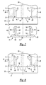
- Figure 1 is an exploded view of an exemplary brake assembly.
- Figures 2-6 are perspective views of various embodiments of mounting clips that may be provided with the brake assembly.
- Figure 7 is a section view of the brake assembly showing a mounting clip prior to installation.
- Figure 8 is a section view of the brake assembly of Figure 6 showing the mounting clip after installation.
- the brake assembly 10 may be provided with a motor vehicle, such as an automobile, truck, or motorcycle.
- the brake assembly 10 may include a hub 20, a rotor 22, a plurality of mounting clips 24, and a plurality of fasteners 26.
- the hub 20 may facilitate coupling of a wheel and an axle.
- the hub 20 may provide a structure for mounting the rotor 22, mounting clip 24, and fastener 26 as will be described in more detail below.
- the hub 20 may be a cast component that may be made of any suitable material, such as an aluminum alloy.
- the hub 20 may be disposed about a center axis 28 and may include a center hole 30, a flange 32, and a rotor mounting portion 34.
- the center hole 30 may be configured to receive or facilitate mounting to an axle.
- the center hole 30 may extend through the hub 20 and may be disposed along the center axis 28.
- Theflange 32 may be disposed at a first end 40 of thehub 20.
- the flange 32 may extend radially outward from the center axis 28 and may be disposed around the center hole 30.
- the flange 32 may have a larger diameter than the rotor mounting portion 34.
- the flange 32 may include a plurality of holes 42 that facilitate mounting of a wheel to the hub 20.
- Eachhole 42 may be disposed along an axis that extends substantially parallel to the center axis 28.
- a fastener such as a mounting stud or lug bolt, may be disposed in each hole 42 to facilitate mounting of the wheel.
- the rotor mounting portion 34 may be integrally formed with the flange 32.
- the rotor mounting portion 34 may be disposed at a second end 44 of the hub 20 that is disposed opposite the first end 40.
- the rotor mounting portion 34 may be disposed around the center hole 30 and may include a collar 50, a set of mounting bosses 52, and a set of pockets 54.
- the collar 50 may extend from the second end 44 of the hub 20 toward the first end 40. More specifically, the collar 50 may extend from the second end 44 to the set of mounting bosses 52.
- the collar 50 may have a generally cylindrical outside diameter surface.
- the set of mounting bosses 52 may be disposed between the collar 50 and the flange 32. Each member of the set of mounting bosses 52may be spaced apart from every other member of the set such that a member of the set of pockets 54 is disposed between adjacent mounting bosses 52.As such, each mounting boss 52 may be disposed radially about the center hole 30, or along different radii that extend from the center axis 28. Moreover, each member of the set of mounting bosses 52 may be arranged with substantially equal spacing such that each mounting boss 52 is spaced apart from an adjacent mounting boss 52 by approximately the same amount or angular distance. In the embodiment shown, ten mounting bosses 52 are provided; however, a greater or lesser number of mounting bosses may be provided in various other embodiments.
- Each member of the set of mounting bosses 52 may have the same or a similar configuration.
- each member of the set of mounting bosses 52 may extend outward from the center axis 28 such that each mounting boss 52 extends further away from the center axis 28 than the collar 50.
- Each mounting boss 52 may include a first surface 60, a second surface 62, a third surface 64, and a fourth surface 66.
- the first surface 60 may face toward the second end 44 of the hub 20 and may extend substantially perpendicular to the center axis 28.
- a mounting hole 68 may extend through the first surface 60.
- the mounting hole 68 may be a blind hole and may include one or more threads that mate with threads on the fastener 26.
- the second surface 62 may extend from the first surface 60 toward the first end 40 of the hub 20. In at least one embodiment, the second surface 62 may extend substantially perpendicular with respect to the first surface 60. The second surface 62 or a portion thereof may be curved or planar in one or more embodiments.
- the third and fourth surfaces64, 66 may extend from the first surface 60 and the second surface 62 along opposite sides of the mounting boss 52.
- the third and fourth surfaces 64, 66 may extend from the first surface 60 toward the first end 40 of the hub 20.
- the third and fourth surfaces 64, 66 may be disposed substantially parallel to each other.
- the third and fourth surfaces 64, 66 may be disposed substantially perpendicular to at least a portion of the first and/or second surfaces 60, 62.
- Each member of the set of pockets 54 may be disposed between adjacent mounting bosses 52. Each pocket 54 may be at least partially defined by a surface of a mounting boss 52. For instance, a pocket 54 may be partially defined by the third surface 64 of one mounting boss 52 and the fourth surface 66 of an adjacent mounting boss 52. In addition, each member of the set of pockets 54 may be at least partially defined by a lower surface 70 and a back surface 72.
- the lower surface 70 may extend along the bottom of a pocket 54 between two adjacent mounting bosses 52. More specifically, the lower surface 70 may extend from the third surface 64 of one mounting boss 52 to the fourth surface 66 of an adjacent mounting boss 52. In at least one embodiment, at least a portion of the lower surface 70 may extend generally parallel to the center axis 28 and may be substantially planar. As such, apocket 54 may have a generally trapezoidal shape when viewed along the center axis 28.
- the back surface 72 may extend along a back side of the pocket 54 that is disposed closer to the first end 40 than the first surface 60 is disposed to the first end 40.
- the back surface 72 may extend from the third surface 64 of one mounting boss 52 to the fourth surface 66 of an adjacent mounting boss 52.
- at least a portion of the back surface 72 may extend substantially perpendicular to the center axis 28 and the lower surface 70.
- the back surface 72 may be substantially planar and may include a recess 74 that extends toward the first end 40 of the hub 20.
- the rotor 22, which may also be called a brake disc, may be provided for slowing or stopping rotation of a wheel that may be coupled to the brake assembly 10.
- the rotor 22 may be centered about the center axis 28 when assembled to the hub 20.
- the rotor 22 may be configured as a generally circular disk and may include a first braking surface 80, a second braking surface 82, an opening 84, and a set of teeth 86.
- the first braking surface 80 may be disposed opposite the second braking surface 82.
- the first and second braking surfaces 80, 82 may be disposed in substantially parallel planes and may be engaged by corresponding brake pads that may be mounted on a brake caliper assembly.
- the brake caliper assembly may mechanically, pneumatically, or hydraulically actuate the brake pads into engagement with the first and second braking surfaces 80, 82 to produce friction that slows or stops rotation of the rotor 22 and an associated wheel.
- the rotor 22 may be made of any suitable material, such as cast iron, reinforced carbon-carbon, or a ceramic composite material. As such, the rotor 22 may be made of a different material than the hub 20 in one or more embodiments.
- the rotor 22 may be ventilated to help dissipate heat generated during braking.
- the rotor 22 includes a plurality of apertures disposed between the first and second braking surfaces 80, 82. Apertures may also be provided in the first and second braking surfaces 80, 82 in one or more embodiments.
- teeth 86 may extend into the opening 84 and toward the center axis 28. In the embodiment shown, ten teeth 86 are provided; however, a greater or lesser number of teeth may be provided in other embodiments.
- Each member of the set of teeth 86 may be generally disposed between the first and second braking surfaces 80, 82 or planes in which these surfaces are disposed.
- one or more teeth 86 may be disposed or extend beyond the first and/or second braking surfaces 80, 82.
- each member of the set of teeth 86 may be spaced apart from other members of the set such that a cavity 88is provided between adjacent teeth 86.
- a connecting surface 90 may at least partially define each cavity 88 and may extend between surfaces of adjacent teeth 86 that partially define a particular cavity 88.
- the connecting surface 90 may be curved in one or more embodiments and may be spaced apart from an adjacent mounting boss 52. Each cavity 88 may receive a corresponding mounting boss 52 while each tooth 86 may be disposed in a corresponding pocket 54 when the rotor 22 is assembled to the hub 20. Each tooth 86 may be spaced apart from an adjacent tooth 86 by approximately the same amount or angular distance.
- the mounting clip 24 may be used to help position and secure the rotor 22 to the hub 20.
- the mounting clip 24 may accommodate thermal expansion of the rotor 22 with respect to the hub 20 as will be discussed in more detail below.
- the mounting clip 24 may be a unitary or one-piece component.
- the mounting clip may be a stamped part that may be made of any suitable material, such as a metal alloy.
- the mounting clip 24 may include a cross member 100, a first arm 102, and a second arm 104.
- the cross member 100 may include a first surface 110 and a second surface 112 disposed opposite the first surface 110.
- the cross member 100 may be substantially planar.
- a through hole 114 may extend through the cross member 100 from the first surface 110 to the second surface 112.
- the through hole 114 may be disposed in substantially the center of the cross member 100.
- the cross member 100 may also be symmetrical with respect to a first axis 120 and a second axis 122 that extends perpendicular to the first axis 120.
- the first and second axes 120, 122 may intersect at the center of the through hole 114.
- a third axis 124 may extend substantially perpendicular to the first and second axes 120, 122.
- the third axis 124 may be a center axis of the through hole 114.
- the first arm 102 and second arm 104 may extend from opposite ends of the cross member 100.
- the first and second arms 102, 104 may be formed by bending material that extends from the ends of the cross member 100 in multiple directions.
- the first and second arms 102, 104 may include a first bend portion or first bend 130 at which material is bent back toward the third axis 124.
- the first bend 130 may be folded to engage the second surface 112of the cross member 100.
- the first bend 130 has a fold angle of about 180 degrees.
- the first and second arms 102, 104 may also include a second bend portion or second bend 132.
- the second bend 132 may begin at or near an end of the first bend 130 and extend away from the second surface 112of the cross member 100. In at least one embodiment, the second bend 132 may have an angle of about 90 degrees.
- a dart 134 may be provided at or along a portion of the second bend 132. The dart 134 may help provide reinforcement for the first and second arms 102, 104 to inhibit bending or buckling.
- the dart 134 may be at least partially provided in a plane that includes the first and third axes 120, 124.
- the dart 134 may be provided by deforming material located near the center of the second bend 132 in a direction that extends away from the second surface 112of the cross member 100 and away from the third axis 124.
- the second bend 132 may include a generally arcuate curved surface above and below the dart 134 in one or more embodiments.
- a first elongate portion 140 may extend from the second bend 132.
- the first elongate portion 140 may be generally planar and may be disposed generally perpendicular to the cross member 100 in one or more embodiments.
- the first elongate portion 140 may include an inner surface 142that may engage the mounting boss 52 and an outer surface 144 disposed opposite the inner surface 142.
- a third bend 150 may be disposed at an end of the first elongate portion 140. At the third bend 150, each arm 102, 104 may be bent back toward the cross member 100. A second elongate portion 152 may extend from an end of the third bend 150. The second elongate portion 152 may include an outer surface 154 that may engage a tooth 86 and an inner surface 156 disposed opposite the outer surface 154. Prior to installation, the third bend 150 may be configuredsuch that the first and second elongate portions 140, 152 are spaced apart and the second elongate portion 152 extends generally toward the first bend 130. As such, the outer surface 144 may be spaced apart from the inner surface 156.
- the second elongate portion 152 may include a cutout 158 disposed at a distal end 160.
- the cutout 158 may provide clearance so that the second elongate portion 152 does not engage the dart 134 and inhibit installation of the mounting clip 24.
- the cutout 158 has a generally semicircular configuration.
- the mounting clip24 is similar to the embodiment shown in Figure 2 except for the addition of a protrusion 170 on the second elongate portion 152.
- the protrusion 170 may extend from the cutout 158 toward the third bend 150.
- the mounting clip is partially fragmented to show a cavity 172that may be formed along the inner surface 156 opposite the protrusion 170.
- the protrusion 170 may provide additional clearance with respect to the dart 134 and/or may help resist disengagement of the mounting clip.
- the mounting clip 24 is similar to the embodiment shown in Figure 2 except for the addition of a protrusion 170' on the second elongate portion 152.
- the protrusion 170' may be disposed between the cutout 158and the third bend 150 and may extend generally from a top surface to a bottom surface of the second elongate portion 152.
- a cavity 172' may be formed along the inner surface156 opposite the protrusion 170' to help resist disengagement of the mounting clip.
- the mounting clip 24 is similar to the embodiment shown in Figure 2 except for the position of the third bend 150.
- the third bend 150 is disposed along a bottom surface 180 of the first elongate portion 140such that the second elongate portion 152 extends generally toward a top surface 182 disposed opposite the bottom side surface 180.
- the second elongate portion 152 may extend generally in the same direction as the second axis 122.
- the mounting clip 24 is similar to the embodiment in Figure 2 except that the first and second elongate portions 140, 152 engage each other near the third bend 150 and then become spaced apart as the second elongate portion 152 extends towards the cross member 100.
- the fastener 26 may be provided to couple the mounting clip 24 to the hub 20.
- the fastener 26 may have any suitable configuration.
- the fastener 26 may be configured as a threaded fastener, such as a bolt, in one or more embodiments.
- the fastener 26 includes a shank 190 and a head 192 that may generally extend along the third axis 124 when assembled to the hub 20.
- the shank 190 may be at least partially threaded and may extend through the through hole 114in the mounting clip 24 and engage the mounting hole 68 in a mounting boss 52.
- the head 192 may be disposed at an end of the shank 190 and may be larger than the through hole 114 in the mounting clip 24.
- the head 192 may include a bearing surface that engages the mounting clip 24 to apply force against the mounting clip 24 to inhibit disengagement of the mounting clip 24.
- FIG. 7 and 8 an exemplary section view of a portion of the brake assembly 10 is shown.
- the rotor 22 is shown disposed on the hub 20 such that each member of the set of teeth 86 engages the back surface 72 of a corresponding member of the set of pockets 54.
- each member of the set of teeth 86 is positioned such that a gap 200 is formed between the tooth 86 and each adjacent mounting boss 52.
- the mounting clip 24 of Figure 2 is shown, it is contemplated that other embodiments of the mounting clip 24 as described above may also be employed.
- the mounting clip 24 is shown prior to assembly.
- the second elongate portion 152 may be spaced apart from the first elongate portion 140. The distance between the first and second elongate portions 140, 152 may exceed the width of the gap 200 between the tooth 86 and the mounting boss 52.
- each arm 102, 104 is aligned and inserted intoa corresponding gap 200.
- the mounting clip 24 is shown in an installed position with the fastener 26 disposed in the through hole 114 in the mounting clip 24 and the mounting hole 68 in a mounting boss 52 as previously described.
- the second elongate portion 152 may bend toward the first elongate portion 140 due to the narrow width of the gap 200.
- the inner surface 156 may then engage the outer surface144, the third bend 150 may have a bend angle of about 180 degrees.
- the first and second arms 102, 104 may inhibit rotation of the mounting clip 24 when installed.
- the second surface 112of the cross member 100 may engage the first surface 60 of the mounting boss 52 andthe first bend 130 may engage a surface of a tooth 86 to hold the rotor 22 against the hub 20 and inhibit movement of rotor 22 along the third axis 124.
- the third bend 150 may also be spaced apart from the back surface 72 on the hub 20 so as to not interfere with insertion of the mounting clip 24.
- the first and second arms 102, 104 may be spaced apart from the lower surface 70 and/or the connecting surface 90 to permit the rotor 22 to expand or move in a radial direction with respect to the center axis 28 to accommodate relative thermal expansion and contraction while maintaining attachment of the rotor 22 to the hub 20. Such relative thermal expansion may be due at least in part to dissimilar materials used to make the hub 20 and rotor 22.
Landscapes
- Engineering & Computer Science (AREA)
- General Engineering & Computer Science (AREA)
- Mechanical Engineering (AREA)
- Braking Arrangements (AREA)
- Connection Of Plates (AREA)
Abstract
Description
- The present application relates to a brake assembly having a mounting clip.
- A brake hub and rotor assembly is disclosed in
U.S. Patent No. 6,604,613 . - In at least one embodiment, a brake assembly is provided. The brake assembly may include a hub, a rotor, and a unitary mounting clip. The hub may have a mounting boss and first and second pockets disposed on opposite sides of the mounting boss. The rotor may be disposed on the hub and may include a first tooth and a second tooth. The first tooth may be disposed in the first pocket. The second tooth may be disposed in the second pocket. The mounting clip may have a first arm and a second arm that extend from opposite ends of a cross member. The first arm may be disposed in the first pocket between the first tooth and the mounting boss. The second arm may be disposed in the second pocket between the second tooth and the mounting boss.
- In at least one embodiment, a brake assembly is provided. The brake assembly may include a hub, a rotor, a unitary mounting clip, and a fastener. The hub may include a center hole and a mounting boss. The mounting boss may be spaced apart from the center hole and may partially define first and second pockets that are disposed on opposite sides of the mounting boss. The rotor may have a first tooth and a second tooth that may engage the hub and may be disposed in the first and second pockets, respectively. The mounting clip may include a cross member, a first arm, and a second arm. The cross member may engage the mounting boss and may be spaced apart from the rotor. The first arm may have a bend portion that extends from a first end of the cross member. The second arm may have a bend portion that extends from a second end of the cross member disposed opposite the first end. The fastener maycouple the mounting clip to the mounting boss. The bend portion of the first arm may engage the first tooth. The bend portion of the second arm may engage the second tooth. The first arm may be disposed in the first pocket and may engage the first tooth and the mounting boss. The second arm may be disposed in the second pocket and may engage the second tooth and the mounting boss.
- In at least one embodiment, a brake assembly is provided. The brake assembly may include a hub, a rotor, a mounting clip, and a fastener. The hub may have a mounting boss and first and second pockets disposed on opposite sides of the mounting boss. The mounting boss may have a first surface that defines a mounting hole. The rotor may have an opening that receives the hub. The rotor may also have a first tooth and a second tooth disposed in the first and second pockets, respectively. The mounting clip may havefirst and second arms that extend from opposite ends of a cross member. The cross member may engage the first surface and may be spaced apart from the rotor. The fastener may extend through the mounting clip and engage the mounting hole. The first arm may havefirst and second elongate portions that are disposed in the first pocket. The first elongate portion may engage the mounting boss and may be spaced apart from the rotor. The second elongate portion may engage the first tooth and may be spaced apart from the hub.
-
Figure 1 is an exploded view of an exemplary brake assembly. -
Figures 2-6 are perspective views of various embodiments of mounting clips that may be provided with the brake assembly. -
Figure 7 is a section view of the brake assembly showing a mounting clip prior to installation. -
Figure 8 is a section view of the brake assembly ofFigure 6 showing the mounting clip after installation. - As required, detailed embodiments of the present invention are disclosed herein; however, it is to be understood that the disclosed embodiments are merely exemplary of the invention that may be embodied in various and alternative forms. The figures are not necessarily to scale; some features may be exaggerated or minimized to show details of particular components. Therefore, specific structural and functional details disclosed herein are not to be interpreted as limiting, but merely as a representative basis for teaching one skilled in the art to variously employ the present invention.
- Referring to
Figure 1 , an exemplary embodiment of abrake assembly 10 is shown. Thebrake assembly 10 may be provided with a motor vehicle, such as an automobile, truck, or motorcycle. Thebrake assembly 10 may include ahub 20, arotor 22, a plurality ofmounting clips 24, and a plurality offasteners 26. - The
hub 20 may facilitate coupling of a wheel and an axle. In addition, thehub 20 may providea structure for mounting therotor 22,mounting clip 24, and fastener 26 as will be described in more detail below. Thehub 20 may be a cast component that may be made of any suitable material, such as an aluminum alloy. Thehub 20 may be disposed about acenter axis 28 and may include acenter hole 30, aflange 32, and arotor mounting portion 34. - The
center hole 30 may be configured to receive or facilitate mounting to an axle. Thecenter hole 30 may extend through thehub 20 and may be disposed along thecenter axis 28. - Theflange 32 may be disposed at a
first end 40 ofthehub 20. Theflange 32 may extend radially outward from thecenter axis 28 and may be disposed around thecenter hole 30. The flange 32may have a larger diameter than therotor mounting portion 34. In addition, the flange 32may include a plurality ofholes 42 that facilitate mounting of a wheel to thehub 20.Eachhole 42 may be disposed along an axis that extends substantially parallel to thecenter axis 28. A fastener, such as a mounting stud or lug bolt, may be disposed in eachhole 42 to facilitate mounting of the wheel. - The
rotor mounting portion 34 may be integrally formed with theflange 32. Therotor mounting portion 34 may be disposed at asecond end 44 of thehub 20 that is disposed opposite thefirst end 40. Therotor mounting portion 34 may be disposed around thecenter hole 30 and may include acollar 50, a set of mountingbosses 52, and a set ofpockets 54. - The
collar 50 may extend from thesecond end 44 of thehub 20 toward thefirst end 40. More specifically, thecollar 50 may extend from thesecond end 44 to the set of mountingbosses 52. Thecollar 50 may have a generally cylindrical outside diameter surface. - The set of mounting
bosses 52 may be disposed between thecollar 50 and theflange 32. Each member of the set of mounting bosses 52may be spaced apart from every other member of the set such that a member of the set ofpockets 54 is disposed between adjacent mounting bosses 52.As such, each mountingboss 52 may be disposed radially about thecenter hole 30, or along different radii that extend from thecenter axis 28. Moreover, each member of the set of mountingbosses 52 may be arranged with substantially equal spacing such that each mountingboss 52 is spaced apart from an adjacent mountingboss 52 by approximately the same amount or angular distance. In the embodiment shown, ten mountingbosses 52 are provided; however, a greater or lesser number of mounting bosses may be provided in various other embodiments. - Each member of the set of mounting
bosses 52 may have the same or a similar configuration. For example, each member of the set of mountingbosses 52 may extend outward from thecenter axis 28 such that each mountingboss 52 extends further away from thecenter axis 28 than thecollar 50. Each mountingboss 52 may include afirst surface 60, asecond surface 62, athird surface 64, and afourth surface 66. - The first surface 60may face toward the
second end 44 of thehub 20 and may extend substantially perpendicular to thecenter axis 28. A mountinghole 68 may extend through thefirst surface 60. The mounting hole 68may be a blind hole and may include one or more threads that mate with threads on thefastener 26. - The
second surface 62 may extend from thefirst surface 60 toward thefirst end 40 of thehub 20. In at least one embodiment, thesecond surface 62 may extend substantially perpendicular with respect to thefirst surface 60. Thesecond surface 62 or a portion thereof may be curved or planar in one or more embodiments. - The third and fourth surfaces64, 66 may extend from the
first surface 60 and thesecond surface 62 along opposite sides of the mountingboss 52. The third andfourth surfaces first surface 60 toward thefirst end 40 of thehub 20. In at least one embodiment, the third andfourth surfaces 64, 66may be disposed substantially parallel to each other. In addition, the third andfourth surfaces second surfaces - Each member of the set of
pockets 54 may be disposed between adjacent mountingbosses 52. Eachpocket 54 may be at least partially defined by a surface of a mountingboss 52. For instance, apocket 54 may be partially defined by thethird surface 64 of one mountingboss 52 and thefourth surface 66 of an adjacent mountingboss 52. In addition, each member of the set ofpockets 54 may be at least partially defined by alower surface 70 and aback surface 72. - The
lower surface 70 may extend along the bottom of apocket 54 between two adjacent mountingbosses 52. More specifically, thelower surface 70 may extend from thethird surface 64 of one mountingboss 52 to thefourth surface 66 of an adjacent mountingboss 52. In at least one embodiment, at least a portion of thelower surface 70 may extend generally parallel to thecenter axis 28 and may be substantially planar. As such,apocket 54 may have a generally trapezoidal shape when viewed along thecenter axis 28. - The
back surface 72 may extend along a back side of thepocket 54 that is disposed closer to thefirst end 40 than thefirst surface 60 is disposed to thefirst end 40. Theback surface 72 may extend from thethird surface 64 of one mountingboss 52 to thefourth surface 66 of an adjacent mountingboss 52. In addition, at least a portion of theback surface 72 may extend substantially perpendicular to thecenter axis 28 and thelower surface 70. In one or more embodiments, theback surface 72 may be substantially planar and may include arecess 74 that extends toward thefirst end 40 of thehub 20. - The
rotor 22, which may also be called a brake disc, may be provided for slowing or stopping rotation of a wheel that may be coupled to thebrake assembly 10. Therotor 22 may be centered about thecenter axis 28 when assembled to thehub 20. Therotor 22 may be configured as a generally circular disk and may include afirst braking surface 80, asecond braking surface 82, anopening 84, and a set ofteeth 86. - The first braking surface 80may be disposed opposite the
second braking surface 82. The first and second braking surfaces 80, 82 may be disposed in substantially parallel planes and may be engaged by corresponding brake pads that may be mounted on a brake caliper assembly. The brake caliper assembly may mechanically, pneumatically, or hydraulically actuate the brake pads into engagement with the first and second braking surfaces 80, 82 to produce friction that slows or stops rotation of therotor 22 and an associated wheel. Therotor 22 may be made of any suitable material, such as cast iron, reinforced carbon-carbon, or a ceramic composite material. As such, therotor 22 may be made of a different material than thehub 20 in one or more embodiments. Therotor 22 may be ventilated to help dissipate heat generated during braking. In the embodiment shown, therotor 22 includes a plurality of apertures disposed between the first and second braking surfaces 80, 82. Apertures may also be provided in the first and second braking surfaces 80, 82 in one or more embodiments. - Theset of
teeth 86 may extend into theopening 84 and toward thecenter axis 28. In the embodiment shown, tenteeth 86 are provided; however, a greater or lesser number of teeth may be provided in other embodiments. Each member of the set ofteeth 86 may be generally disposed between the first and second braking surfaces 80, 82 or planes in which these surfaces are disposed. Optionally, one ormore teeth 86 may be disposed or extend beyond the first and/or second braking surfaces 80, 82. In addition, each member of the set ofteeth 86 may be spaced apart from other members of the set such that a cavity 88is provided betweenadjacent teeth 86. A connectingsurface 90 may at least partially define eachcavity 88 and may extend between surfaces ofadjacent teeth 86 that partially define aparticular cavity 88. The connectingsurface 90 may be curved in one or more embodiments and may be spaced apart from an adjacent mountingboss 52. Eachcavity 88 may receive a corresponding mountingboss 52 while eachtooth 86 may be disposed in acorresponding pocket 54 when therotor 22 is assembled to thehub 20. Eachtooth 86 may be spaced apart from anadjacent tooth 86 by approximately the same amount or angular distance. - Referring to
Figure 2 , a first embodiment of a mountingclip 24 is shown. The mountingclip 24 may be used to help position and secure therotor 22 to thehub 20. In addition, the mountingclip 24 may accommodate thermal expansion of therotor 22 with respect to thehub 20 as will be discussed in more detail below. The mountingclip 24 may be a unitary or one-piece component. The mounting clip may be a stamped part that may be made of any suitable material, such as a metal alloy. The mountingclip 24 may include across member 100, afirst arm 102, and asecond arm 104. - The
cross member 100 may include afirst surface 110 and asecond surface 112 disposed opposite thefirst surface 110. In at least one embodiment, thecross member 100 may be substantially planar. A throughhole 114 may extend through thecross member 100 from thefirst surface 110 to thesecond surface 112. The throughhole 114 may be disposed in substantially the center of thecross member 100. Thecross member 100 may also be symmetrical with respect to afirst axis 120 and asecond axis 122 that extends perpendicular to thefirst axis 120. The first andsecond axes hole 114. In addition, athird axis 124 may extend substantially perpendicular to the first andsecond axes third axis 124 may be a center axis of the throughhole 114. - The
first arm 102 andsecond arm 104 may extend from opposite ends of thecross member 100. The first andsecond arms cross member 100 in multiple directions. For instance, the first andsecond arms first bend 130 at which material is bent back toward thethird axis 124. As such, thefirst bend 130 may be folded to engage the second surface 112of thecross member 100. In the embodiment shown, thefirst bend 130 has a fold angle of about 180 degrees. - The first and
second arms second bend 132. Thesecond bend 132 may begin at or near an end of thefirst bend 130 and extend away from the second surface 112of thecross member 100. In at least one embodiment, thesecond bend 132 may have an angle of about 90 degrees. Adart 134 may be provided at or along a portion of thesecond bend 132. Thedart 134 may help provide reinforcement for the first andsecond arms dart 134 may be at least partially provided in a plane that includes the first andthird axes dart 134 may be provided by deforming material located near the center of thesecond bend 132 in a direction that extends away from the second surface 112of thecross member 100 and away from thethird axis 124. Thus, thesecond bend 132 may include a generally arcuate curved surface above and below thedart 134 in one or more embodiments. - A first
elongate portion 140 may extend from thesecond bend 132. The firstelongate portion 140 may be generally planar and may be disposed generally perpendicular to thecross member 100 in one or more embodiments. The firstelongate portion 140 may include an inner surface 142that may engage the mountingboss 52 and anouter surface 144 disposed opposite theinner surface 142. - A
third bend 150 may be disposed at an end of the firstelongate portion 140. At thethird bend 150, eacharm cross member 100. A secondelongate portion 152 may extend from an end of thethird bend 150. The secondelongate portion 152 may include an outer surface 154 that may engage atooth 86 and aninner surface 156 disposed opposite the outer surface 154. Prior to installation, thethird bend 150 may be configuredsuch that the first and secondelongate portions elongate portion 152 extends generally toward thefirst bend 130. As such, theouter surface 144 may be spaced apart from theinner surface 156. - The second
elongate portion 152 may include acutout 158 disposed at adistal end 160. Thecutout 158 may provide clearance so that the secondelongate portion 152 does not engage thedart 134 and inhibit installation of the mountingclip 24. In the embodiment shown, thecutout 158 has a generally semicircular configuration. - Referring to
Figures 3-5 , additional embodiments of the mounting clip are shown. - In
Figure 3 , the mounting clip24 is similar to the embodiment shown inFigure 2 except for the addition of aprotrusion 170 on the secondelongate portion 152. The protrusion 170may extend from thecutout 158 toward thethird bend 150. The mounting clip is partially fragmented to show a cavity 172that may be formed along theinner surface 156 opposite theprotrusion 170. Theprotrusion 170 may provide additional clearance with respect to thedart 134 and/or may help resist disengagement of the mounting clip. - In
Figure 4 , the mountingclip 24 is similar to the embodiment shown inFigure 2 except for the addition of aprotrusion 170' on the secondelongate portion 152. Theprotrusion 170' may be disposed between the cutout 158and thethird bend 150 and may extend generally from a top surface to a bottom surface of the secondelongate portion 152. Acavity 172' may be formed along the inner surface156 opposite theprotrusion 170' to help resist disengagement of the mounting clip. - In
Figure 5 , the mountingclip 24 is similar to the embodiment shown inFigure 2 except for the position of thethird bend 150. In this embodiment, thethird bend 150 is disposed along abottom surface 180 of the first elongate portion 140such that the secondelongate portion 152 extends generally toward atop surface 182 disposed opposite thebottom side surface 180. As such, the second elongate portion 152may extend generally in the same direction as thesecond axis 122. - In
Figure 6 , the mountingclip 24 is similar to the embodiment inFigure 2 except that the first and secondelongate portions third bend 150 and then become spaced apart as the secondelongate portion 152 extends towards thecross member 100. - Referring again to
Figure 1 , thefastener 26 may be provided to couple the mountingclip 24 to thehub 20. Thefastener 26 may have any suitable configuration. For example, thefastener 26 may be configured as a threaded fastener, such as a bolt, in one or more embodiments. In the embodiment shown, thefastener 26 includes ashank 190 and ahead 192 that may generally extend along thethird axis 124 when assembled to thehub 20. Theshank 190 may be at least partially threaded and may extend through the through hole 114in the mountingclip 24 and engage the mountinghole 68 in a mountingboss 52. Thehead 192 may be disposed at an end of theshank 190 and may be larger than the throughhole 114 in the mountingclip 24. Thehead 192 may include a bearing surface that engages the mountingclip 24 to apply force against the mountingclip 24 to inhibit disengagement of the mountingclip 24. - Referring to
Figures 7 and 8 , an exemplary section view of a portion of thebrake assembly 10 is shown. InFigures 7 and 8 , therotor 22 is shown disposed on thehub 20 such that each member of the set ofteeth 86 engages theback surface 72 of a corresponding member of the set ofpockets 54. In addition, each member of the set ofteeth 86 is positioned such that agap 200 is formed between thetooth 86 and each adjacent mountingboss 52. Although the mountingclip 24 ofFigure 2 is shown, it is contemplated that other embodiments of the mountingclip 24 as described above may also be employed. - In
Figure 7 , the mountingclip 24 is shown prior to assembly. Prior to assembly, the second elongate portion 152may be spaced apart from the firstelongate portion 140. The distance between the first and secondelongate portions gap 200 between thetooth 86 and the mountingboss 52. To assemble the mountingclip 24, eacharm 102, 104is aligned and inserted intoacorresponding gap 200. - In
Figure 8 , the mountingclip 24 is shown in an installed position with thefastener 26 disposed in the throughhole 114 in the mountingclip 24 and the mountinghole 68 in a mountingboss 52 as previously described. During installation of the mountingclip 24, the second elongate portion 152may bend toward the firstelongate portion 140 due to the narrow width of thegap 200. Theinner surface 156 may then engage the outer surface144, thethird bend 150 may have a bend angle of about 180 degrees. The first andsecond arms clip 24 when installed. - In addition, the second surface 112of the
cross member 100 may engage thefirst surface 60 of the mountingboss 52 andthefirst bend 130 may engage a surface of atooth 86 to hold therotor 22 against thehub 20 and inhibit movement ofrotor 22 along thethird axis 124. Thethird bend 150 may also be spaced apart from theback surface 72 on thehub 20 so as to not interfere with insertion of the mountingclip 24. The first andsecond arms lower surface 70 and/or the connectingsurface 90 to permit therotor 22 to expand or move in a radial direction with respect to thecenter axis 28 to accommodate relative thermal expansion and contraction while maintaining attachment of therotor 22 to thehub 20. Such relative thermal expansion may be due at least in part to dissimilar materials used to make thehub 20 androtor 22. - While exemplary embodiments are described above, it is not intended that these embodiments describe all possible forms of the invention. Rather, the words used in the specification are words of description rather than limitation, and it is understood that various changes may be made without departing from the spirit and scope of the invention. Additionally, the features of various implementing embodiments may be combined to form further embodiments of the invention.
Claims (15)
- A brake assembly comprising:a hub having a mounting boss and first and second pockets disposed on opposite sides of the mounting boss;a rotor disposed on the hub, the rotor having a first tooth and a second tooth disposed in the first and second pockets, respectively; andaunitary mounting clip having a first arm and a second arm that extend from opposite ends of a cross member;wherein the first arm is disposed in the first pocket between the first tooth and the mounting boss and the second arm is disposed in the second pocket between the second tooth and the mounting boss.
- The brake assembly of claim 1 wherein the mounting boss includes a mounting hole and the mounting clip includes a through hole, a fastener extends through the mounting hole and intothe through hole to secure the mounting clip to the hub, preferably the cross member engages a first surface of the mounting boss that extends from the first pocket to the second pocket, wherein themounting hole has a substantially circular opening that is completely defined within the first surface.
- The brake assembly of claim 1 wherein the first pocket includesa lower surface and a back surface that extends from the lower surface, wherein the lower and back surfaces extend from the mounting boss to a second mounting boss and the first tooth engages the lower andback surfaces, preferably the mounting clip is spaced apart from the lower and back surfaces.
- The brake assembly of claim 1 wherein the first arm includes first and second elongate portions that are at least partially spaced apart before the first arm is inserted into the first pocket, preferably the first and second elongate portions are biased into engagement when the first arm is inserted into the first pocket between the first tooth and the mounting boss.
- A brake assembly comprising:a hub having a center hole, a mounting boss that is spaced apart from the center hole and that at least partially defines first and second pockets that are disposed on opposite sides of the mounting boss;a rotor having a first tooth and a second tooth that engage the hub and are disposed in the first and second pockets, respectively;aunitary mounting clip including:across member that engages the mounting boss and is spaced apart from the rotor;afirst arm having a bend portion that extends from a first end of the cross member;
anda second arm having a bend portion that extends from a second end of the cross member disposed opposite the first end; anda fastener that couples the mounting clip to the mounting boss;wherein the bend portion of the first arm engages the first tooth, the bend portion of the second arm engages the second tooth, the first arm is disposed in the first pocket and engages the first tooth and the mounting boss, and the second arm is disposed in the second pocket and engages the second tooth and the mounting boss. - The brake assembly of claim 5 wherein the first arm includes a second bend portion that is spaced apart from the bend portion of the first arm and a first elongate portion that extends from the second bend portion and away from the cross member.
- The brake assembly of claim 6 wherein the first arm includes a third bend portion disposed at an end of the first elongate portion that is disposed opposite the second bend portion and a second elongate portion that extends from the third bend portion toward the cross member.
- The brake assembly of claim 6 wherein the first elongate portion includes a dart disposed proximate the cross member, preferably wherein the dart is disposed at the second bend portion.
- The brake assembly of claim 8 further comprising a second elongate portion that extends from the second bend portion, wherein the second elongate portion includes a cutoutdisposed at a distal end that receives the dart.
- A brake assembly comprising:a hub that includes:a mounting boss having a first surface that defines a mounting hole ;andfirst and second pockets disposed on opposite sides of the mounting boss;a rotor having an opening that receives the hub and a first tooth and a second tooth disposed in the first and second pockets, respectively;a mounting clip having a first arm and a second arm that extend from opposite ends of a cross member; anda fastener that extends through the mounting clip and engages the mounting hole;whereinthe cross member engages the first surface and is spaced apart from the rotor;
andwherein the first arm has first and second elongate portions that are disposed in the first pocket, wherein the first elongate portion engages the mounting boss and is spaced apart from the rotor and the second elongate portion engages the first tooth and is spaced apart from the hub. - The brake assembly of claim 10 wherein the second arm has a first elongate portion and a second elongate portion that are disposed in the second pocket, wherein the first elongate portion of the second arm engages the mounting boss and is spaced apart from the rotor and the second elongate portion of the second arm engages the second tooth and is spaced apart from the hub.
- The brake assembly of claim 10 wherein the second elongate portion includes a protrusion and a cavity disposed between the protrusion and the first elongate portion.
- The brake assembly of claim 12 wherein the protrusion and the cavity extend from a distal end of the second elongate portion away from the cross member.
- The brake assembly of claim 12 wherein the protrusion and the cavity are spaced apart from a distal end of the second elongate portion.
- The brake assembly of claim 12 wherein the first and second elongate portions extend from a bend and are disposed such that the first elongate portion engages the second elongate portion, preferably wherein the bend is disposed opposite a distal end of the second elongate portion.
Applications Claiming Priority (1)
| Application Number | Priority Date | Filing Date | Title |
|---|---|---|---|
| US13/171,997 US8418817B2 (en) | 2011-06-29 | 2011-06-29 | Brake assembly having a mounting clip |
Publications (2)
| Publication Number | Publication Date |
|---|---|
| EP2543905A1 true EP2543905A1 (en) | 2013-01-09 |
| EP2543905B1 EP2543905B1 (en) | 2016-08-10 |
Family
ID=46318995
Family Applications (1)
| Application Number | Title | Priority Date | Filing Date |
|---|---|---|---|
| EP12172443.9A Active EP2543905B1 (en) | 2011-06-29 | 2012-06-18 | Brake assembly having a mounting clip |
Country Status (5)
| Country | Link |
|---|---|
| US (1) | US8418817B2 (en) |
| EP (1) | EP2543905B1 (en) |
| JP (1) | JP5613200B2 (en) |
| CN (1) | CN102853006A (en) |
| BR (1) | BR102012016239B8 (en) |
Cited By (4)
| Publication number | Priority date | Publication date | Assignee | Title |
|---|---|---|---|---|
| EP2639472A1 (en) * | 2012-03-12 | 2013-09-18 | PE Automotive GmbH & Co. KG | Wear plate for a brake disc |
| DE202014008786U1 (en) | 2014-11-05 | 2014-12-18 | Michael Claus | Brake device for wheel brakes of a vehicle |
| DE102014016343A1 (en) | 2014-11-05 | 2016-05-12 | Michael Claus | Brake device for wheel brakes of a vehicle |
| WO2020114931A1 (en) * | 2018-12-05 | 2020-06-11 | Saf-Holland Gmbh | Brake disk arrangement |
Families Citing this family (16)
| Publication number | Priority date | Publication date | Assignee | Title |
|---|---|---|---|---|
| JP3408377B2 (en) | 1996-06-26 | 2003-05-19 | 望月 ▲たく▼夫 | Pressure fluid energy conversion apparatus and method |
| KR20130019127A (en) * | 2011-08-16 | 2013-02-26 | 현대자동차주식회사 | Brake disc using different materials |
| DE102011116118B4 (en) * | 2011-10-15 | 2013-07-04 | Daimler Ag | brake disc |
| US9303705B2 (en) | 2014-07-25 | 2016-04-05 | Bendix Spicer Foundation Brake Llc | Brake disc and mounting arrangement for a brake disc |
| ES2747301T3 (en) * | 2016-06-28 | 2020-03-10 | Adolf Kochsiek | Disc brake unit |
| JP6649204B2 (en) * | 2016-08-23 | 2020-02-19 | 株式会社ユタカ技研 | Floating brake disc |
| DE102016119878B4 (en) * | 2016-10-19 | 2020-08-06 | Knorr-Bremse Systeme für Nutzfahrzeuge GmbH | Brake disc / hub connection |
| KR101897367B1 (en) * | 2016-12-01 | 2018-09-13 | 현대자동차주식회사 | Brake disk |
| DE102017002869A1 (en) * | 2017-03-24 | 2018-09-27 | Wabco Gmbh | Pole wheel on a wheel of a vehicle |
| DE102017129684B4 (en) * | 2017-12-13 | 2024-01-25 | Knorr-Bremse Systeme für Nutzfahrzeuge GmbH | Brake discs/hub connection |
| CN108105290A (en) * | 2017-12-15 | 2018-06-01 | 重庆市鑫奕星机电制造有限公司 | A kind of disc brake brake disc and motorcycle |
| WO2019130188A1 (en) | 2017-12-29 | 2019-07-04 | Freni Brembo S.P.A. | Brake disc for a disc brake and method |
| US11629765B2 (en) | 2020-05-15 | 2023-04-18 | Arvinmeritor Technology, Llc | Brake rotor |
| US20230228287A1 (en) * | 2022-01-18 | 2023-07-20 | Fred Barton | Automatic Greaser Retainer |
| EP4293246B1 (en) * | 2022-06-13 | 2025-02-19 | Goodrich Corporation | Rotor clip for brake assembly |
| CN120056644A (en) * | 2023-11-28 | 2025-05-30 | 阿文美驰技术有限责任公司 | Hub and brake rotor assembly |
Citations (5)
| Publication number | Priority date | Publication date | Assignee | Title |
|---|---|---|---|---|
| DE19807184C1 (en) * | 1998-02-20 | 2000-04-20 | Knorr Bremse Systeme | Brake disk for commercial vehicle |
| WO2002025135A1 (en) * | 2000-09-21 | 2002-03-28 | Knorr-Bremse Systeme für Nutzfahrzeuge GmbH | Brake disk/hub assembly for vehicle disk brakes |
| US6467588B1 (en) * | 1998-09-02 | 2002-10-22 | Knorr-Bremse Systeme Fuer Nutzfahrzeuge Gmbh | Wheel and/or brake disk hub and brake disk |
| US6604613B2 (en) | 2000-03-24 | 2003-08-12 | Performance Friction Corporation | Brake hub with floating rotor and mounting flange allowing simplified rotor removal and replacement |
| WO2008026990A1 (en) * | 2006-08-28 | 2008-03-06 | Scania Cv Ab | Brake disc and hub device for a motor vehicle |
Family Cites Families (12)
| Publication number | Priority date | Publication date | Assignee | Title |
|---|---|---|---|---|
| DE19544559C1 (en) * | 1995-11-30 | 1997-07-03 | Knorr Bremse Systeme | Two-piece brake disc, especially for commercial vehicle disc brakes |
| DE29823371U1 (en) * | 1998-02-20 | 1999-06-10 | Knorr-Bremse Systeme für Nutzfahrzeuge GmbH, 80809 München | Two-piece brake disc |
| DE19918069B4 (en) * | 1999-04-21 | 2004-06-24 | Knorr-Bremse Systeme für Nutzfahrzeuge GmbH | Brake disc / hub combination and intermediate elements for a brake disc / hub combination |
| FR2799520B1 (en) * | 1999-10-08 | 2002-01-25 | Messier Bugatti | DEVICE FOR AXIAL FIXATION OF A VENTILATED BRAKING DISC ON THE HUB OF A WHEEL OF A MOTOR VEHICLE |
| US6267210B1 (en) | 2000-03-24 | 2001-07-31 | Performance Friction Corporation | Brake hub with floating rotor |
| GB0300983D0 (en) * | 2003-01-16 | 2003-02-19 | A P Racing Ltd | Brake disc |
| US6997292B2 (en) | 2003-01-17 | 2006-02-14 | Performance Friction Corporation | Brake rotor attachment assembly that promotes in plane uniform torque transfer distribution |
| EP1863653B1 (en) * | 2005-04-01 | 2016-03-23 | Performance Friction Corporation | Direct drive braking system including an integrated package bearing |
| DE102005023380B3 (en) * | 2005-05-17 | 2006-10-19 | Knorr-Bremse Systeme für Nutzfahrzeuge GmbH | Brakes Disc/hub connection consists of periphery support element and brake disc hub which has an intermediate element located between hub and disc and protruding from an intermediate chamber |
| US7610999B2 (en) * | 2005-08-30 | 2009-11-03 | Robert Bosch Gmbh | Wheel hub |
| US9291227B2 (en) * | 2005-09-30 | 2016-03-22 | Performance Friction Corporation | Brake rotor and abs tone ring attachment assembly that promotes in plane uniform torque transfer distribution |
| SE531445C2 (en) * | 2006-09-19 | 2009-04-07 | Scania Cv Abp | Disc brake hub assembly |
-
2011
- 2011-06-29 US US13/171,997 patent/US8418817B2/en active Active
-
2012
- 2012-06-18 EP EP12172443.9A patent/EP2543905B1/en active Active
- 2012-06-26 JP JP2012142773A patent/JP5613200B2/en active Active
- 2012-06-29 CN CN2012102257463A patent/CN102853006A/en active Pending
- 2012-06-29 BR BR102012016239A patent/BR102012016239B8/en active Search and Examination
Patent Citations (5)
| Publication number | Priority date | Publication date | Assignee | Title |
|---|---|---|---|---|
| DE19807184C1 (en) * | 1998-02-20 | 2000-04-20 | Knorr Bremse Systeme | Brake disk for commercial vehicle |
| US6467588B1 (en) * | 1998-09-02 | 2002-10-22 | Knorr-Bremse Systeme Fuer Nutzfahrzeuge Gmbh | Wheel and/or brake disk hub and brake disk |
| US6604613B2 (en) | 2000-03-24 | 2003-08-12 | Performance Friction Corporation | Brake hub with floating rotor and mounting flange allowing simplified rotor removal and replacement |
| WO2002025135A1 (en) * | 2000-09-21 | 2002-03-28 | Knorr-Bremse Systeme für Nutzfahrzeuge GmbH | Brake disk/hub assembly for vehicle disk brakes |
| WO2008026990A1 (en) * | 2006-08-28 | 2008-03-06 | Scania Cv Ab | Brake disc and hub device for a motor vehicle |
Cited By (8)
| Publication number | Priority date | Publication date | Assignee | Title |
|---|---|---|---|---|
| EP2639472A1 (en) * | 2012-03-12 | 2013-09-18 | PE Automotive GmbH & Co. KG | Wear plate for a brake disc |
| DE202014008786U1 (en) | 2014-11-05 | 2014-12-18 | Michael Claus | Brake device for wheel brakes of a vehicle |
| DE202015002501U1 (en) | 2014-11-05 | 2015-06-10 | Michael Claus | Brake device for wheel brakes of a vehicle |
| DE102014016343A1 (en) | 2014-11-05 | 2016-05-12 | Michael Claus | Brake device for wheel brakes of a vehicle |
| DE102015004258A1 (en) | 2014-11-05 | 2016-05-12 | Michael Claus | Brake device for wheel brakes of one vehicle |
| WO2020114931A1 (en) * | 2018-12-05 | 2020-06-11 | Saf-Holland Gmbh | Brake disk arrangement |
| CN112930450A (en) * | 2018-12-05 | 2021-06-08 | 塞夫霍兰德有限公司 | Brake disc device |
| US11999189B2 (en) | 2018-12-05 | 2024-06-04 | Saf-Holland Gmbh | Brake disc arrangement |
Also Published As
| Publication number | Publication date |
|---|---|
| EP2543905B1 (en) | 2016-08-10 |
| CN102853006A (en) | 2013-01-02 |
| JP2013011347A (en) | 2013-01-17 |
| BR102012016239A2 (en) | 2013-11-26 |
| JP5613200B2 (en) | 2014-10-22 |
| BR102012016239B8 (en) | 2021-08-10 |
| US8418817B2 (en) | 2013-04-16 |
| BR102012016239B1 (en) | 2021-05-25 |
| US20130001029A1 (en) | 2013-01-03 |
Similar Documents
| Publication | Publication Date | Title |
|---|---|---|
| US8418817B2 (en) | Brake assembly having a mounting clip | |
| JP5791487B2 (en) | Composite type disc rotor | |
| JP5855398B2 (en) | Disc brake pad assembly | |
| US20110240420A1 (en) | Disk brake rotor | |
| CN102341612A (en) | Brake disk | |
| JP2006057718A (en) | Floating calliper type disk brake | |
| JP4668844B2 (en) | Opposite piston type disc brake | |
| EP3855040B1 (en) | Pad spring for disc brake and disc brake device | |
| US20180347648A1 (en) | Brake pad | |
| JP2005121174A (en) | Opposed piston type disk brake | |
| BR112016021757B1 (en) | BRAKE PAD SET | |
| RU2628555C2 (en) | Brake shoe and braking unit | |
| EP1590577A1 (en) | Brake disc assembly | |
| JP6202434B2 (en) | Disc brake device | |
| KR20150076790A (en) | Disc brake device combined parking brake with different materials | |
| CN105492794B (en) | Heavy die forging bottom plate | |
| JP5879032B2 (en) | Disc brake | |
| JP2019536948A (en) | Wheel brake device | |
| JP5297341B2 (en) | Caliper body for disc brakes for vehicles | |
| KR20230062040A (en) | Floating Disc Assembly for Vehicles | |
| EP3575624A1 (en) | Disc brake pad and disc brake device | |
| US12270442B2 (en) | Pad clip for disc brake apparatus and disc brake apparatus | |
| JP4736092B2 (en) | Disc brake rotor | |
| JP2006144856A (en) | Brake disk | |
| JP6115089B2 (en) | Disc brake pad |
Legal Events
| Date | Code | Title | Description |
|---|---|---|---|
| PUAI | Public reference made under article 153(3) epc to a published international application that has entered the european phase |
Free format text: ORIGINAL CODE: 0009012 |
|
| AK | Designated contracting states |
Kind code of ref document: A1 Designated state(s): AL AT BE BG CH CY CZ DE DK EE ES FI FR GB GR HR HU IE IS IT LI LT LU LV MC MK MT NL NO PL PT RO RS SE SI SK SM TR |
|
| AX | Request for extension of the european patent |
Extension state: BA ME |
|
| 17P | Request for examination filed |
Effective date: 20130709 |
|
| RBV | Designated contracting states (corrected) |
Designated state(s): AL AT BE BG CH CY CZ DE DK EE ES FI FR GB GR HR HU IE IS IT LI LT LU LV MC MK MT NL NO PL PT RO RS SE SI SK SM TR |
|
| GRAP | Despatch of communication of intention to grant a patent |
Free format text: ORIGINAL CODE: EPIDOSNIGR1 |
|
| RIC1 | Information provided on ipc code assigned before grant |
Ipc: F16D 65/12 20060101AFI20150129BHEP |
|
| INTG | Intention to grant announced |
Effective date: 20150303 |
|
| INTG | Intention to grant announced |
Effective date: 20151203 |
|
| GRAS | Grant fee paid |
Free format text: ORIGINAL CODE: EPIDOSNIGR3 |
|
| GRAP | Despatch of communication of intention to grant a patent |
Free format text: ORIGINAL CODE: EPIDOSNIGR1 |
|
| GRAS | Grant fee paid |
Free format text: ORIGINAL CODE: EPIDOSNIGR3 |
|
| INTG | Intention to grant announced |
Effective date: 20160610 |
|
| GRAA | (expected) grant |
Free format text: ORIGINAL CODE: 0009210 |
|
| AK | Designated contracting states |
Kind code of ref document: B1 Designated state(s): AL AT BE BG CH CY CZ DE DK EE ES FI FR GB GR HR HU IE IS IT LI LT LU LV MC MK MT NL NO PL PT RO RS SE SI SK SM TR |
|
| REG | Reference to a national code |
Ref country code: GB Ref legal event code: FG4D |
|
| REG | Reference to a national code |
Ref country code: CH Ref legal event code: EP Ref country code: AT Ref legal event code: REF Ref document number: 819349 Country of ref document: AT Kind code of ref document: T Effective date: 20160815 |
|
| REG | Reference to a national code |
Ref country code: IE Ref legal event code: FG4D |
|
| REG | Reference to a national code |
Ref country code: DE Ref legal event code: R096 Ref document number: 602012021388 Country of ref document: DE |
|
| REG | Reference to a national code |
Ref country code: SE Ref legal event code: TRGR |
|
| REG | Reference to a national code |
Ref country code: LT Ref legal event code: MG4D |
|
| REG | Reference to a national code |
Ref country code: NL Ref legal event code: MP Effective date: 20160810 |
|
| REG | Reference to a national code |
Ref country code: AT Ref legal event code: MK05 Ref document number: 819349 Country of ref document: AT Kind code of ref document: T Effective date: 20160810 |
|
| PG25 | Lapsed in a contracting state [announced via postgrant information from national office to epo] |
Ref country code: IT Free format text: LAPSE BECAUSE OF FAILURE TO SUBMIT A TRANSLATION OF THE DESCRIPTION OR TO PAY THE FEE WITHIN THE PRESCRIBED TIME-LIMIT Effective date: 20160810 Ref country code: RS Free format text: LAPSE BECAUSE OF FAILURE TO SUBMIT A TRANSLATION OF THE DESCRIPTION OR TO PAY THE FEE WITHIN THE PRESCRIBED TIME-LIMIT Effective date: 20160810 Ref country code: NL Free format text: LAPSE BECAUSE OF FAILURE TO SUBMIT A TRANSLATION OF THE DESCRIPTION OR TO PAY THE FEE WITHIN THE PRESCRIBED TIME-LIMIT Effective date: 20160810 Ref country code: LT Free format text: LAPSE BECAUSE OF FAILURE TO SUBMIT A TRANSLATION OF THE DESCRIPTION OR TO PAY THE FEE WITHIN THE PRESCRIBED TIME-LIMIT Effective date: 20160810 Ref country code: FI Free format text: LAPSE BECAUSE OF FAILURE TO SUBMIT A TRANSLATION OF THE DESCRIPTION OR TO PAY THE FEE WITHIN THE PRESCRIBED TIME-LIMIT Effective date: 20160810 Ref country code: NO Free format text: LAPSE BECAUSE OF FAILURE TO SUBMIT A TRANSLATION OF THE DESCRIPTION OR TO PAY THE FEE WITHIN THE PRESCRIBED TIME-LIMIT Effective date: 20161110 Ref country code: HR Free format text: LAPSE BECAUSE OF FAILURE TO SUBMIT A TRANSLATION OF THE DESCRIPTION OR TO PAY THE FEE WITHIN THE PRESCRIBED TIME-LIMIT Effective date: 20160810 Ref country code: IS Free format text: LAPSE BECAUSE OF FAILURE TO SUBMIT A TRANSLATION OF THE DESCRIPTION OR TO PAY THE FEE WITHIN THE PRESCRIBED TIME-LIMIT Effective date: 20161210 |
|
| PG25 | Lapsed in a contracting state [announced via postgrant information from national office to epo] |
Ref country code: ES Free format text: LAPSE BECAUSE OF FAILURE TO SUBMIT A TRANSLATION OF THE DESCRIPTION OR TO PAY THE FEE WITHIN THE PRESCRIBED TIME-LIMIT Effective date: 20160810 Ref country code: PT Free format text: LAPSE BECAUSE OF FAILURE TO SUBMIT A TRANSLATION OF THE DESCRIPTION OR TO PAY THE FEE WITHIN THE PRESCRIBED TIME-LIMIT Effective date: 20161212 Ref country code: AT Free format text: LAPSE BECAUSE OF FAILURE TO SUBMIT A TRANSLATION OF THE DESCRIPTION OR TO PAY THE FEE WITHIN THE PRESCRIBED TIME-LIMIT Effective date: 20160810 Ref country code: GR Free format text: LAPSE BECAUSE OF FAILURE TO SUBMIT A TRANSLATION OF THE DESCRIPTION OR TO PAY THE FEE WITHIN THE PRESCRIBED TIME-LIMIT Effective date: 20161111 Ref country code: PL Free format text: LAPSE BECAUSE OF FAILURE TO SUBMIT A TRANSLATION OF THE DESCRIPTION OR TO PAY THE FEE WITHIN THE PRESCRIBED TIME-LIMIT Effective date: 20160810 Ref country code: LV Free format text: LAPSE BECAUSE OF FAILURE TO SUBMIT A TRANSLATION OF THE DESCRIPTION OR TO PAY THE FEE WITHIN THE PRESCRIBED TIME-LIMIT Effective date: 20160810 |
|
| PG25 | Lapsed in a contracting state [announced via postgrant information from national office to epo] |
Ref country code: RO Free format text: LAPSE BECAUSE OF FAILURE TO SUBMIT A TRANSLATION OF THE DESCRIPTION OR TO PAY THE FEE WITHIN THE PRESCRIBED TIME-LIMIT Effective date: 20160810 Ref country code: EE Free format text: LAPSE BECAUSE OF FAILURE TO SUBMIT A TRANSLATION OF THE DESCRIPTION OR TO PAY THE FEE WITHIN THE PRESCRIBED TIME-LIMIT Effective date: 20160810 |
|
| REG | Reference to a national code |
Ref country code: DE Ref legal event code: R097 Ref document number: 602012021388 Country of ref document: DE |
|
| PG25 | Lapsed in a contracting state [announced via postgrant information from national office to epo] |
Ref country code: BE Free format text: LAPSE BECAUSE OF FAILURE TO SUBMIT A TRANSLATION OF THE DESCRIPTION OR TO PAY THE FEE WITHIN THE PRESCRIBED TIME-LIMIT Effective date: 20160810 Ref country code: SM Free format text: LAPSE BECAUSE OF FAILURE TO SUBMIT A TRANSLATION OF THE DESCRIPTION OR TO PAY THE FEE WITHIN THE PRESCRIBED TIME-LIMIT Effective date: 20160810 Ref country code: SK Free format text: LAPSE BECAUSE OF FAILURE TO SUBMIT A TRANSLATION OF THE DESCRIPTION OR TO PAY THE FEE WITHIN THE PRESCRIBED TIME-LIMIT Effective date: 20160810 Ref country code: CZ Free format text: LAPSE BECAUSE OF FAILURE TO SUBMIT A TRANSLATION OF THE DESCRIPTION OR TO PAY THE FEE WITHIN THE PRESCRIBED TIME-LIMIT Effective date: 20160810 Ref country code: BG Free format text: LAPSE BECAUSE OF FAILURE TO SUBMIT A TRANSLATION OF THE DESCRIPTION OR TO PAY THE FEE WITHIN THE PRESCRIBED TIME-LIMIT Effective date: 20161110 Ref country code: DK Free format text: LAPSE BECAUSE OF FAILURE TO SUBMIT A TRANSLATION OF THE DESCRIPTION OR TO PAY THE FEE WITHIN THE PRESCRIBED TIME-LIMIT Effective date: 20160810 |
|
| PLBE | No opposition filed within time limit |
Free format text: ORIGINAL CODE: 0009261 |
|
| STAA | Information on the status of an ep patent application or granted ep patent |
Free format text: STATUS: NO OPPOSITION FILED WITHIN TIME LIMIT |
|
| REG | Reference to a national code |
Ref country code: FR Ref legal event code: PLFP Year of fee payment: 6 |
|
| 26N | No opposition filed |
Effective date: 20170511 |
|
| PG25 | Lapsed in a contracting state [announced via postgrant information from national office to epo] |
Ref country code: SI Free format text: LAPSE BECAUSE OF FAILURE TO SUBMIT A TRANSLATION OF THE DESCRIPTION OR TO PAY THE FEE WITHIN THE PRESCRIBED TIME-LIMIT Effective date: 20160810 |
|
| PG25 | Lapsed in a contracting state [announced via postgrant information from national office to epo] |
Ref country code: MC Free format text: LAPSE BECAUSE OF FAILURE TO SUBMIT A TRANSLATION OF THE DESCRIPTION OR TO PAY THE FEE WITHIN THE PRESCRIBED TIME-LIMIT Effective date: 20160810 |
|
| REG | Reference to a national code |
Ref country code: CH Ref legal event code: PL |
|
| GBPC | Gb: european patent ceased through non-payment of renewal fee |
Effective date: 20170618 |
|
| REG | Reference to a national code |
Ref country code: IE Ref legal event code: MM4A |
|
| PG25 | Lapsed in a contracting state [announced via postgrant information from national office to epo] |
Ref country code: GB Free format text: LAPSE BECAUSE OF NON-PAYMENT OF DUE FEES Effective date: 20170618 Ref country code: LI Free format text: LAPSE BECAUSE OF NON-PAYMENT OF DUE FEES Effective date: 20170630 Ref country code: LU Free format text: LAPSE BECAUSE OF NON-PAYMENT OF DUE FEES Effective date: 20170618 Ref country code: IE Free format text: LAPSE BECAUSE OF NON-PAYMENT OF DUE FEES Effective date: 20170618 Ref country code: CH Free format text: LAPSE BECAUSE OF NON-PAYMENT OF DUE FEES Effective date: 20170630 |
|
| REG | Reference to a national code |
Ref country code: FR Ref legal event code: PLFP Year of fee payment: 7 |
|
| PG25 | Lapsed in a contracting state [announced via postgrant information from national office to epo] |
Ref country code: MT Free format text: LAPSE BECAUSE OF NON-PAYMENT OF DUE FEES Effective date: 20170618 |
|
| PG25 | Lapsed in a contracting state [announced via postgrant information from national office to epo] |
Ref country code: AL Free format text: LAPSE BECAUSE OF FAILURE TO SUBMIT A TRANSLATION OF THE DESCRIPTION OR TO PAY THE FEE WITHIN THE PRESCRIBED TIME-LIMIT Effective date: 20160810 |
|
| PG25 | Lapsed in a contracting state [announced via postgrant information from national office to epo] |
Ref country code: HU Free format text: LAPSE BECAUSE OF FAILURE TO SUBMIT A TRANSLATION OF THE DESCRIPTION OR TO PAY THE FEE WITHIN THE PRESCRIBED TIME-LIMIT; INVALID AB INITIO Effective date: 20120618 |
|
| PG25 | Lapsed in a contracting state [announced via postgrant information from national office to epo] |
Ref country code: CY Free format text: LAPSE BECAUSE OF NON-PAYMENT OF DUE FEES Effective date: 20160810 |
|
| PG25 | Lapsed in a contracting state [announced via postgrant information from national office to epo] |
Ref country code: MK Free format text: LAPSE BECAUSE OF FAILURE TO SUBMIT A TRANSLATION OF THE DESCRIPTION OR TO PAY THE FEE WITHIN THE PRESCRIBED TIME-LIMIT Effective date: 20160810 |
|
| PG25 | Lapsed in a contracting state [announced via postgrant information from national office to epo] |
Ref country code: TR Free format text: LAPSE BECAUSE OF FAILURE TO SUBMIT A TRANSLATION OF THE DESCRIPTION OR TO PAY THE FEE WITHIN THE PRESCRIBED TIME-LIMIT Effective date: 20160810 |
|
| P01 | Opt-out of the competence of the unified patent court (upc) registered |
Effective date: 20230531 |
|
| PGFP | Annual fee paid to national office [announced via postgrant information from national office to epo] |
Ref country code: DE Payment date: 20250627 Year of fee payment: 14 |
|
| PGFP | Annual fee paid to national office [announced via postgrant information from national office to epo] |
Ref country code: FR Payment date: 20250625 Year of fee payment: 14 |
|
| PGFP | Annual fee paid to national office [announced via postgrant information from national office to epo] |
Ref country code: SE Payment date: 20250627 Year of fee payment: 14 |