EP2543895A1 - Grommet - Google Patents
Grommet Download PDFInfo
- Publication number
- EP2543895A1 EP2543895A1 EP11750641A EP11750641A EP2543895A1 EP 2543895 A1 EP2543895 A1 EP 2543895A1 EP 11750641 A EP11750641 A EP 11750641A EP 11750641 A EP11750641 A EP 11750641A EP 2543895 A1 EP2543895 A1 EP 2543895A1
- Authority
- EP
- European Patent Office
- Prior art keywords
- leg
- shaft body
- contacting portion
- main body
- grommet
- Prior art date
- Legal status (The legal status is an assumption and is not a legal conclusion. Google has not performed a legal analysis and makes no representation as to the accuracy of the status listed.)
- Granted
Links
Images



Classifications
-
- F—MECHANICAL ENGINEERING; LIGHTING; HEATING; WEAPONS; BLASTING
- F16—ENGINEERING ELEMENTS AND UNITS; GENERAL MEASURES FOR PRODUCING AND MAINTAINING EFFECTIVE FUNCTIONING OF MACHINES OR INSTALLATIONS; THERMAL INSULATION IN GENERAL
- F16B—DEVICES FOR FASTENING OR SECURING CONSTRUCTIONAL ELEMENTS OR MACHINE PARTS TOGETHER, e.g. NAILS, BOLTS, CIRCLIPS, CLAMPS, CLIPS OR WEDGES; JOINTS OR JOINTING
- F16B19/00—Bolts without screw-thread; Pins, including deformable elements; Rivets
- F16B19/04—Rivets; Spigots or the like fastened by riveting
- F16B19/08—Hollow rivets; Multi-part rivets
- F16B19/10—Hollow rivets; Multi-part rivets fastened by expanding mechanically
-
- F—MECHANICAL ENGINEERING; LIGHTING; HEATING; WEAPONS; BLASTING
- F16—ENGINEERING ELEMENTS AND UNITS; GENERAL MEASURES FOR PRODUCING AND MAINTAINING EFFECTIVE FUNCTIONING OF MACHINES OR INSTALLATIONS; THERMAL INSULATION IN GENERAL
- F16B—DEVICES FOR FASTENING OR SECURING CONSTRUCTIONAL ELEMENTS OR MACHINE PARTS TOGETHER, e.g. NAILS, BOLTS, CIRCLIPS, CLAMPS, CLIPS OR WEDGES; JOINTS OR JOINTING
- F16B19/00—Bolts without screw-thread; Pins, including deformable elements; Rivets
- F16B19/04—Rivets; Spigots or the like fastened by riveting
- F16B19/08—Hollow rivets; Multi-part rivets
- F16B19/10—Hollow rivets; Multi-part rivets fastened by expanding mechanically
- F16B19/1027—Multi-part rivets
- F16B19/1036—Blind rivets
- F16B19/1081—Blind rivets fastened by a drive-pin
Definitions
- the present invention relates to improvement in a grommet provided with a shaft body and a main body into which the shaft body is pressed.
- grommet also called as a pin grommet constituted of a shaft body and a main body into which the shaft body is pressed.
- a grommet has a configuration in which the shaft body is pressed into the main body from a state where a leg of the main body is inserted into a through hole formed in a fixed object, thereby spreading the leg to fix the fixed object.
- a grommet in which its leg has two different spread points pressed by a pressing portion of a pin through insertion of the pin (shaft body) into the leg of the grommet (main body) (refer to Patent literature 1).
- a grommet while the leg is being elastically deformed at the spread point on its front end side, the leg starts to be elastically deformed at the spread point on its bottom end side.
- the pressure resistance of the pin onto the grommet cannot be sufficiently reduced.
- Fig. 15 shows the concept.
- a horizontal axis represents a pin pressing stroke, and the stroke becomes larger toward the right.
- a vertical axis represents a pressure resistance.
- a dot-and-dash line shows a pressure resistance deemed to be caused by the leg having the spread point on its front end side
- a broken line shows a pressure resistance deemed to be caused by the leg having the spread point on its bottom end side
- a solid line shows a combined resistance of the two resistances.
- Patent literature 1 Japanese Patent No. 4201217
- a main object of the present invention is to reduce a pressure resistance of a shaft body to a main body constituting a grommet as little as possible without impairing the function of the grommet.
- a grommet includes a shaft body, and a main body having a head and a leg spread by the shaft body pressed from a side of the head with elastic deformation, and the shaft body includes a first contacting portion that contacts a contacted portion of the leg by pressing, and a second contacting portion located in a rear of the first contacting portion in the pressing direction, and a part of the leg is spread by the first contacting portion and then, another part of the leg is spread by further pressing the shaft body.
- the contacted portion is a protrusion that protrudes toward an inside of the leg, and the first contacting portion or the second contacting portion contacts the protrusion by pressing of the shaft body.
- both of the contacting portions are formed such that a formation area of the first contacting portion and a formation area of the second contacting portion in the shaft body are displaced from each other by a certain angle in a circumferential direction of the shaft body.
- the leg In the state where the first contacting portion of the shaft body is not in contact with the contacted portion, the leg is not elastically deformed. Subsequently, when the shaft body is pressed up to a position where the first contacting portion contacts the contacted portion, only a part of the leg is spread with elastic deformation. Then, another part of the leg is not elastically deformed until the part of the leg is completely spread. Then, when the shaft body is pressed up to a position where the second contacting portion contacts the contacted portion, another part of the leg is spread with elastic deformation. Thereby, the grommet holds the fixed object between the head and the leg to fix the fixed object.
- the leg By configuring the outer shape of a cross section of the leg of the main body so as to substantially conform to a circular arc of a virtual circle on an outer side of the leg, and substantially conform to sides of a virtual rectangle on an inner side of the leg, as compared to the case where the outer shape of the cross section is configured to conform to the circular arc of the virtual circle on both of the inner and outer sides, the leg can be spread by pressing of the shaft body more easily.
- the pressure resistance of the shaft body to the main body constituting the grommet can be reduced as little as possible without impairing the function of the grommet.
- the grommet in accordance with this embodiment comprises a shaft body 1 and a main body 2 into which the shaft body 1 is pressed, and the shaft body 1 is pressed into the main body 2 from a state where a leg 21 of the main body 2 is inserted into a through hole Pa formed in a fixed object P, thereby spreading the leg 21 to fix the fixed object P.
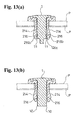
- such a grommet is used such that the leg 21 of the main body 2 is inserted into the through hole Pa in each of a plurality of fixed objects P from a state where the through holes Pa are overlapped so as to communicate with each other, thereby spreading the leg 21 to fix the plurality of fixed objects P via the grommet ( Figs. 13(a), 13(b) ).
- the main body 2 includes a head 20 and the leg 21 spread by the shaft body 1 pressed from the side of the head 20 with elastic deformation.
- the head 20 is shaped like a disc having a larger outer diameter than the through hole Pa.
- the leg 21 has a thickness that can be inserted into the through hole Pa.
- the leg 21 has a leg bottom 211 integrally communicating with one surface of the head 20, and protrudes in a direction orthogonal to the one surface.
- the head 20 has a circular receiving hole 20a for the shaft body 1.
- the leg 21 comprises four oblong plate-like elastic leg pieces 214, 214... of the same size and shape, wherein each has wide inner and outer surfaces, and a receiving space 213 of the shaft body 1, which is surrounded by the four elastic leg pieces 214, 214..., communicates with the receiving hole 20a.
- One end of each of the elastic leg pieces 214 integrally communicates with an edge of the receiving hole 20a and its bottom constitutes the leg bottom 211, and the other end constitutes a leg terminal 212 of the leg 21.
- the elastic leg pieces 214 are arranged at substantially regular intervals.
- each elastic leg piece 214 integrally communicates with a protruding end of a communicating portion 215 that protrudes inward from the edge of the receiving hole 20a.
- the communicating portion 215 has the substantially same width as the elastic leg piece 214.
- the other ends of the elastic leg pieces 214 respectively have a protrusion 216 that protrudes toward the inside of the leg 21. Due to the protrusion 216 of each of the elastic leg pieces 214, the receiving space 213 is narrowed on the side of the leg terminal 212 of the leg 21.
- the protrusion 216 includes an inclined surface 216a facing the head 20.
- a flat surface 216c in parallel to a center line of the leg 21 not shown in the figures exists between a top 216b of the protrusion 216 and the other end of each of the elastic leg pieces 214.
- An inclined guide surface 214a that gradually decreases an outer diameter of the leg 21 toward the other end of the elastic leg piece 214 is formed on the outer surface of each of the elastic leg pieces 214.
- the inclined guide surface 214a enables smooth insertion of the leg 21 of the main body 2 into the through hole Pa of the fixed object P.
- each of the elastic leg pieces 214 has a curved surface 214b conforming to the circular arc of the virtual circle as its outer surface, and has a flat surface 216c conforming to the sides of the virtual rectangle as its inner surface ( Fig. 7 , Fig. 8 , Fig. 10 ).
- the leg 21 is spread more easily by pressing the shaft body 1 with elastic deformation.
- the shaft body 1 When defining the protrusion 216 of the leg 21 as a contacted portion to be contacted by the pressing, the shaft body 1 includes a first contacting portion 10 that contacts the contacted portion, and a second contacting portion 11 located in the rear of the first contacting portion 10 in the pressing direction. By spreading a part of the leg 21 by the first contacting portion 10 and then, pressing the shaft body 1 thereinto, the second contacting portion 11 contacts the contacted portion, thereby spreading another part of the leg 21.
- the leg 21 is not elastically deformed ( Figs. 9(a), 9(b) ).
- the shaft body 1 is pressed up to a position where the first contacting portion 10 contacts the contacted portion, only a part of the leg 21 is spread with elastic deformation.
- the four elastic leg pieces 214, 214... constituting the leg 21 only the two elastic leg pieces 214 located back-to-back are bent outward ( Figs. 11(a), 11(b) ).
- the remaining two elastic leg pieces 214 as another part of the leg 21 are not elastically deformed until the part of the leg 21 is completely spread.
- Fig. 14 shows the concept.
- a horizontal axis represents a pressing stroke of the shaft body 1, and the stroke becomes larger toward the right.
- a vertical axis represents pressure resistances.
- a dot-and-dash line shows a pressure resistance deemed to be caused by the part of the leg 21 of the main body 2
- a broken line shows a pressure resistance deemed to be caused by the another part of the leg 21 of the main body 2
- a solid line shows a combined resistance of the two resistances.
- the shaft body 1 includes a main body portion 12 substantially shaped like a rectangular column and a disc portion 13. One end of the main body portion 12 integrally communicates with one surface of the disc portion 13.
- the main body portion 12 has a thickness that can be inserted into the receiving space 213 of the leg 21 through the receiving hole 20a of the main body 2.
- the disc portion 13 has a larger outer diameter than the thickness of the main body portion 12, such that the shaft body 1 can be pressed into the main body 2 up to a position where the disc portion 13 contacts the other surface of the head 20 of the main body 2.
- the receiving hole 20a is blocked by the disc portion 13 at a position where the shaft body 1 is completely pressed into the main body 2.
- the shape of a cross section of the main body portion 12 of the shaft body 1 substantially conforms to a virtual rectangle. That is, the main body portion 12 of the shaft body 1 includes four side surfaces 120, 120.... In the illustrated example, a corner 121 between the adjacent side surfaces 120 is shaped like a rib extending in an axial direction of the shaft body 1, and each of the side surfaces 120 is shaped like a groove between the right and left corners 121. A distance between the right and left corners 121 substantially corresponds to the width of the elastic leg piece 214.
- the shaft body 1 is inserted into the receiving space 213 from the side of its other end through the receiving hole 20a in the state where the elastic leg pieces 214 are respectively stored in the right and left corners 121 surrounding one side surface 120.
- a distance between the two side surfaces 120, 120 located back-to-back in the shaft body 1 substantially corresponds to a distance between inner surfaces configured as the flat surfaces 214c of the two opposed elastic leg pieces 214, 214 of the leg 21 of the main body 2.
- recesses 122 are formed wherein each is formed between the adjacent corners 121 so as to be opened outward at the other end of the shaft body 1 and retract a terminal 120a of the side surface 120 rearward in the pressing direction further than the other end of the main body portion 12.
- the recesses 122 of the two side surfaces 120 located back-to-back among the four side surfaces 120, 120 ... of the main body portion 12 retract the terminal 120a rearward in the pressing direction of the shaft body 1. That is, the main body portion 12 has the recesses 122 located back-to-back.
- a distance between the bottom surfaces of the recesses 122, 122 at the two locations is smaller than the distance between the protrusions 216 of the two opposed elastic leg pieces 214 constituting the leg 21 of the main body 2.
- the terminal 120a of the side surfaces 120 which is retracted by the recesses 122, constitutes the second contacting portion 11, and the terminal 120a of the remaining side surfaces 120 constitutes the first contacting portion 10.
- a formation area of the first contacting portion 10 and a formation area of the second contacting portion 11 in the shaft body 1 are displaced from each other by a certain angle in a circumferential direction of the shaft body 1.
- the second contacting portion 11 is displaced from the first contacting portion 10 by 90 degrees.
- a portion closer to the terminal than an intermediate portion 120b of the side surface 120, the terminal 120a of which is retracted by the recess 122, is extended outward as an engaging portion 120c, and the elastic leg pieces 214 that contact the protrusions 216 of the second contacting portions 11 and are spread, are slightly bent back at positions where the tops216b of the protrusions 216 exceed the terminal, and the tops 216b are hooked at the engaging portions 120c ( Figs. 13(a), 13(b) ).
- a recess 121a recessed from the side of the side surface 120 is formed at each position closer to the disc portion 13 than the second contacting portion 11 in the right and left corners 121 interposing the side surface 120, the terminal of which is retracted by the recess 122, therebetween, and a part of the shaft body 1 is inserted into the main body 2 up to a position when an edge of the communicating portion 215 enters into the recess 121a.
- the main body 2 can be temporarily engaged with the shaft body 1.
- the edge of the communicating portion 215 escapes from the recess 121a allowing the pressing of the shaft body 1.
- the elastic deformation characteristics can be easily imparted to the areas that should have the characteristics in the above-mentioned grommet by making the whole or a part of the grommet from synthetic resin.
Landscapes
- Engineering & Computer Science (AREA)
- General Engineering & Computer Science (AREA)
- Mechanical Engineering (AREA)
- Insertion Pins And Rivets (AREA)
- Automotive Seat Belt Assembly (AREA)
- Buckles (AREA)
Abstract

Description
- The present invention relates to improvement in a grommet provided with a shaft body and a main body into which the shaft body is pressed.
- There exists a grommet also called as a pin grommet constituted of a shaft body and a main body into which the shaft body is pressed. Such a grommet has a configuration in which the shaft body is pressed into the main body from a state where a leg of the main body is inserted into a through hole formed in a fixed object, thereby spreading the leg to fix the fixed object.
- There is proposed a grommet in which its leg has two different spread points pressed by a pressing portion of a pin through insertion of the pin (shaft body) into the leg of the grommet (main body) (refer to Patent literature 1). In such a grommet, while the leg is being elastically deformed at the spread point on its front end side, the leg starts to be elastically deformed at the spread point on its bottom end side. Thus, the pressure resistance of the pin onto the grommet cannot be sufficiently reduced.
Fig. 15 shows the concept. InFig. 15 , a horizontal axis represents a pin pressing stroke, and the stroke becomes larger toward the right. A vertical axis represents a pressure resistance. InFig. 15 , a dot-and-dash line shows a pressure resistance deemed to be caused by the leg having the spread point on its front end side, a broken line shows a pressure resistance deemed to be caused by the leg having the spread point on its bottom end side, and a solid line shows a combined resistance of the two resistances. - Patent literature 1: Japanese Patent No.
4201217 - A main object of the present invention is to reduce a pressure resistance of a shaft body to a main body constituting a grommet as little as possible without impairing the function of the grommet.
- To attain the object, according to the present invention, a grommet includes a shaft body, and a main body having a head and a leg spread by the shaft body pressed from a side of the head with elastic deformation, and the shaft body includes a first contacting portion that contacts a contacted portion of the leg by pressing, and a second contacting portion located in a rear of the first contacting portion in the pressing direction, and a part of the leg is spread by the first contacting portion and then, another part of the leg is spread by further pressing the shaft body.
- In one preferred embodiment, the contacted portion is a protrusion that protrudes toward an inside of the leg, and the first contacting portion or the second contacting portion contacts the protrusion by pressing of the shaft body. In another preferred embodiment, both of the contacting portions are formed such that a formation area of the first contacting portion and a formation area of the second contacting portion in the shaft body are displaced from each other by a certain angle in a circumferential direction of the shaft body.
- In the state where the first contacting portion of the shaft body is not in contact with the contacted portion, the leg is not elastically deformed. Subsequently, when the shaft body is pressed up to a position where the first contacting portion contacts the contacted portion, only a part of the leg is spread with elastic deformation. Then, another part of the leg is not elastically deformed until the part of the leg is completely spread. Then, when the shaft body is pressed up to a position where the second contacting portion contacts the contacted portion, another part of the leg is spread with elastic deformation. Thereby, the grommet holds the fixed object between the head and the leg to fix the fixed object. In such grommet, since the spreading of the part of the leg of the main body and the spreading of another part of the leg do not occur at the same time, the pressure resistance of the shaft body onto the main body can be suppressed below a certain value while spreading the part and another part of the leg together in a final fixed state.
- By configuring the outer shape of a cross section of the leg of the main body so as to substantially conform to a circular arc of a virtual circle on an outer side of the leg, and substantially conform to sides of a virtual rectangle on an inner side of the leg, as compared to the case where the outer shape of the cross section is configured to conform to the circular arc of the virtual circle on both of the inner and outer sides, the leg can be spread by pressing of the shaft body more easily.
- According to the present invention, the pressure resistance of the shaft body to the main body constituting the grommet can be reduced as little as possible without impairing the function of the grommet.
-
-
Fig. 1 is an exploded perspective view showing a grommet in accordance with an embodiment of the present invention. -
Fig. 2 is a partial sectional side view showing a shaft body constituting the grommet. -
Fig. 3 is a sectional view showing the grommet taken along a line A-A inFig. 2 . -
Fig. 4 is a partial sectional side view showing the shaft body constituting the grommet, and showing the shaft body when viewed in a direction displaced from that inFig. 2 by 90 degrees. -
Fig. 5 is a bottom view showing the shaft body constituting the grommet. -
Fig. 6 is a partial sectional side view showing a main body constituting the grommet. -
Fig. 7 is a plan view showing the main body constituting the grommet. -
Fig. 8 is a bottom view showing the main body constituting the grommet. -
Figs. 9(a) and 9(b) are sectional views showing a state where the main body constituting the grommet is inserted into a through hole of an object, and a cross-sectional position inFig. 9(b) is displaced from a cross-sectional position inFig. 9(a) by 90 degrees. -
Fig. 10 is a horizontal sectional view showing the grommet inFigs. 9(a), 9(b) . -
Figs. 11(a) and 11(b) are sectional views showing a state where the shaft body starts to be pressed into the main body from the state inFigs. 9(a), 9(b) , and a cross-sectional position inFig. 11(b) is displaced from a cross-sectional position inFig. 11(a) by 90 degrees. -
Figs. 12(a) and 12(b) are sectional views showing a state where the shaft body is further pressed into the main body from the state inFigs. 11(a), 11(b) , and a cross-sectional position inFig. 12(b) is displaced from a cross-sectional position inFig. 12(a) by 90 degrees. -
Figs. 13(a) and 13(b) are sectional views showing a state where the shaft body is completely pressed into the main body, and a cross-sectional position inFig. 13(b) is displaced from a cross-sectional position inFig. 13(a) by 90 degrees. -
Fig. 14 is a conceptual view showing correlation between a pressing stroke of the shaft body and a pressure resistance in the grommet according to the present invention. -
Fig. 15 is a conceptual view showing correlation between a pressing stroke of the shaft body and a pressure resistance in a conventional grommet. - A typical embodiment of the present invention will be described below with reference to
Fig. 1 to Fig. 14 . The grommet in accordance with this embodiment comprises ashaft body 1 and amain body 2 into which theshaft body 1 is pressed, and theshaft body 1 is pressed into themain body 2 from a state where aleg 21 of themain body 2 is inserted into a through hole Pa formed in a fixed object P, thereby spreading theleg 21 to fix the fixed object P. Typically, such a grommet is used such that theleg 21 of themain body 2 is inserted into the through hole Pa in each of a plurality of fixed objects P from a state where the through holes Pa are overlapped so as to communicate with each other, thereby spreading theleg 21 to fix the plurality of fixed objects P via the grommet (Figs. 13(a), 13(b) ). - The
main body 2 includes ahead 20 and theleg 21 spread by theshaft body 1 pressed from the side of thehead 20 with elastic deformation. - In an illustrated example, the
head 20 is shaped like a disc having a larger outer diameter than the through hole Pa. Theleg 21 has a thickness that can be inserted into the through hole Pa. - The
leg 21 has aleg bottom 211 integrally communicating with one surface of thehead 20, and protrudes in a direction orthogonal to the one surface. In the illustrated example, thehead 20 has acircular receiving hole 20a for theshaft body 1. Theleg 21 comprises four oblong plate-likeelastic leg pieces receiving space 213 of theshaft body 1, which is surrounded by the fourelastic leg pieces receiving hole 20a. One end of each of theelastic leg pieces 214 integrally communicates with an edge of thereceiving hole 20a and its bottom constitutes theleg bottom 211, and the other end constitutes a leg terminal 212 of theleg 21. Theelastic leg pieces 214 are arranged at substantially regular intervals. - In the illustrated example, the one end of each
elastic leg piece 214 integrally communicates with a protruding end of a communicatingportion 215 that protrudes inward from the edge of thereceiving hole 20a. The communicatingportion 215 has the substantially same width as theelastic leg piece 214. - The other ends of the
elastic leg pieces 214 respectively have aprotrusion 216 that protrudes toward the inside of theleg 21. Due to theprotrusion 216 of each of theelastic leg pieces 214, thereceiving space 213 is narrowed on the side of the leg terminal 212 of theleg 21. Theprotrusion 216 includes aninclined surface 216a facing thehead 20. Aflat surface 216c in parallel to a center line of theleg 21 not shown in the figures exists between atop 216b of theprotrusion 216 and the other end of each of theelastic leg pieces 214. Aninclined guide surface 214a that gradually decreases an outer diameter of theleg 21 toward the other end of theelastic leg piece 214 is formed on the outer surface of each of theelastic leg pieces 214. Theinclined guide surface 214a enables smooth insertion of theleg 21 of themain body 2 into the through hole Pa of the fixed object P. - The outer shape of a cross section of the
leg 21 substantially conforms to a circular arc of a virtual circle on the outer side of theleg 21, and substantially conforms to sides of a virtual rectangle on the inner side of theleg 21. That is, each of theelastic leg pieces 214 has acurved surface 214b conforming to the circular arc of the virtual circle as its outer surface, and has aflat surface 216c conforming to the sides of the virtual rectangle as its inner surface (Fig. 7 ,Fig. 8 ,Fig. 10 ). Thereby, in the example, as compared to the case where the outer shape of the cross section of theleg 21 substantially conforms to the circular arc of the virtual circle on both of the inner and outer sides of theleg 21, theleg 21 is spread more easily by pressing theshaft body 1 with elastic deformation. - When defining the
protrusion 216 of theleg 21 as a contacted portion to be contacted by the pressing, theshaft body 1 includes a first contactingportion 10 that contacts the contacted portion, and a second contactingportion 11 located in the rear of the first contactingportion 10 in the pressing direction. By spreading a part of theleg 21 by the first contactingportion 10 and then, pressing theshaft body 1 thereinto, the second contactingportion 11 contacts the contacted portion, thereby spreading another part of theleg 21. - That is, in the state where the first contacting
portion 10 of theshaft body 1 is not in contact with the contacted portion, theleg 21 is not elastically deformed (Figs. 9(a), 9(b) ). Next, when theshaft body 1 is pressed up to a position where the first contactingportion 10 contacts the contacted portion, only a part of theleg 21 is spread with elastic deformation. In the illustrated example, at this time, among the fourelastic leg pieces leg 21, only the twoelastic leg pieces 214 located back-to-back are bent outward (Figs. 11(a), 11(b) ). The remaining twoelastic leg pieces 214 as another part of theleg 21 are not elastically deformed until the part of theleg 21 is completely spread. Then, when theshaft body 1 is pressed up to the position where the second contactingportion 11 contacts the contacted portion, the remaining twoelastic leg pieces 214 as another part of theleg 21 are spread with elastic deformation (Figs. 12(a), 12(b) ,Figs. 13(a), 13(b) ). Thereby, the grommet holds the fixed object P between thehead 20 and theleg 21 to fix the fixed object P. - In the grommet in this embodiment, since the spreading of a part of the
leg 21 of themain body 2 and the spreading of another part of theleg 21 do not occur at the same time, the pressure resistance of theshaft body 1 to themain body 2 can be suppressed below a certain value while spreading the part and another part of theleg 21 together in a final fixed state.Fig. 14 shows the concept. InFig. 14 , a horizontal axis represents a pressing stroke of theshaft body 1, and the stroke becomes larger toward the right. A vertical axis represents pressure resistances. InFig. 14 , a dot-and-dash line shows a pressure resistance deemed to be caused by the part of theleg 21 of themain body 2, a broken line shows a pressure resistance deemed to be caused by the another part of theleg 21 of themain body 2, and a solid line shows a combined resistance of the two resistances. - Specifically, the
shaft body 1 includes amain body portion 12 substantially shaped like a rectangular column and adisc portion 13. One end of themain body portion 12 integrally communicates with one surface of thedisc portion 13. Themain body portion 12 has a thickness that can be inserted into the receivingspace 213 of theleg 21 through the receivinghole 20a of themain body 2. Thedisc portion 13 has a larger outer diameter than the thickness of themain body portion 12, such that theshaft body 1 can be pressed into themain body 2 up to a position where thedisc portion 13 contacts the other surface of thehead 20 of themain body 2. The receivinghole 20a is blocked by thedisc portion 13 at a position where theshaft body 1 is completely pressed into themain body 2. - At each point of the
main body portion 12, the shape of a cross section of themain body portion 12 of theshaft body 1 substantially conforms to a virtual rectangle. That is, themain body portion 12 of theshaft body 1 includes fourside surfaces corner 121 between the adjacent side surfaces 120 is shaped like a rib extending in an axial direction of theshaft body 1, and each of the side surfaces 120 is shaped like a groove between the right and leftcorners 121. A distance between the right and leftcorners 121 substantially corresponds to the width of theelastic leg piece 214. In the illustrated example, theshaft body 1 is inserted into the receivingspace 213 from the side of its other end through the receivinghole 20a in the state where theelastic leg pieces 214 are respectively stored in the right and leftcorners 121 surrounding oneside surface 120. A distance between the twoside surfaces shaft body 1 substantially corresponds to a distance between inner surfaces configured as theflat surfaces 214c of the two opposedelastic leg pieces leg 21 of themain body 2. - On the side of the other end as the front end in the pressing direction of the
main body portion 12 of theshaft body 1, recesses 122 are formed wherein each is formed between theadjacent corners 121 so as to be opened outward at the other end of theshaft body 1 and retract a terminal 120a of theside surface 120 rearward in the pressing direction further than the other end of themain body portion 12. In the illustrated example, therecesses 122 of the twoside surfaces 120 located back-to-back among the fourside surfaces main body portion 12 retract the terminal 120a rearward in the pressing direction of theshaft body 1. That is, themain body portion 12 has therecesses 122 located back-to-back. A distance between the bottom surfaces of therecesses protrusions 216 of the two opposedelastic leg pieces 214 constituting theleg 21 of themain body 2. - That is, in this embodiment, the terminal 120a of the side surfaces 120, which is retracted by the
recesses 122, constitutes the second contactingportion 11, and the terminal 120a of the remaining side surfaces 120 constitutes the first contactingportion 10. Thus, in this embodiment, a formation area of the first contactingportion 10 and a formation area of the second contactingportion 11 in theshaft body 1 are displaced from each other by a certain angle in a circumferential direction of theshaft body 1. In the illustrated example, the second contactingportion 11 is displaced from the first contactingportion 10 by 90 degrees. - In this embodiment, a portion closer to the terminal than an
intermediate portion 120b of theside surface 120, the terminal 120a of which is retracted by therecess 122, is extended outward as an engagingportion 120c, and theelastic leg pieces 214 that contact theprotrusions 216 of the second contactingportions 11 and are spread, are slightly bent back at positions where the tops216b of theprotrusions 216 exceed the terminal, and the tops 216b are hooked at the engagingportions 120c (Figs. 13(a), 13(b) ). - In this embodiment, a
recess 121a recessed from the side of theside surface 120 is formed at each position closer to thedisc portion 13 than the second contactingportion 11 in the right and leftcorners 121 interposing theside surface 120, the terminal of which is retracted by therecess 122, therebetween, and a part of theshaft body 1 is inserted into themain body 2 up to a position when an edge of the communicatingportion 215 enters into therecess 121a. Thereby, in the state where the first contactingportion 10 is not in contact with theprotrusion 216, themain body 2 can be temporarily engaged with theshaft body 1. When theshaft body 1 is pressed from this temporary engaged state, the edge of the communicatingportion 215 escapes from therecess 121a allowing the pressing of theshaft body 1. - The elastic deformation characteristics can be easily imparted to the areas that should have the characteristics in the above-mentioned grommet by making the whole or a part of the grommet from synthetic resin.
- Specification, Claims, figures and Abstract of Japanese Patent Application No.
2010-046316 filed on March 3, 2010
Claims (4)
- A grommet comprising:a shaft body; anda main body including a head, and a leg spread, with elastic deformation, by the shaft body pressed from a side of the head;wherein the shaft body includes a first contacting portion that contacts a contacted portion of the leg by pressing, and a second contacting portion located at a rear side relative to the first contacting portion in a pressing direction, anda part of the leg is spread by the first contacting portion and thereafter, another part of the leg is spread by further pressing the shaft body.
- The grommet according to claim 1, wherein the contacted portion is a protrusion that protrudes toward an inside of the leg, and the first contacting portion or the second contacting portion contacts the protrusion by pressing the shaft body.
- The grommet according to claim 1 or 2, wherein the contacting portions are formed such that a formation area of the first contacting portion and a formation area of the second contacting portion in the shaft body are displaced from each other by a predetermined angle in a circumferential direction of the shaft body.
- The grommet according to any one of claims 1 to 3, wherein a shape of a cross section of the leg of the main body substantially conforms to a circular arc of a virtual circle on an outer side of the leg, and substantially conforms to sides of a virtual rectangle on an inner side of the leg.
Applications Claiming Priority (2)
| Application Number | Priority Date | Filing Date | Title |
|---|---|---|---|
| JP2010046316A JP5307053B2 (en) | 2010-03-03 | 2010-03-03 | Grommet |
| PCT/JP2011/054604 WO2011108531A1 (en) | 2010-03-03 | 2011-03-01 | Grommet |
Publications (3)
| Publication Number | Publication Date |
|---|---|
| EP2543895A1 true EP2543895A1 (en) | 2013-01-09 |
| EP2543895A4 EP2543895A4 (en) | 2017-05-31 |
| EP2543895B1 EP2543895B1 (en) | 2019-07-17 |
Family
ID=44542182
Family Applications (1)
| Application Number | Title | Priority Date | Filing Date |
|---|---|---|---|
| EP11750641.0A Active EP2543895B1 (en) | 2010-03-03 | 2011-03-01 | Push rivet |
Country Status (5)
| Country | Link |
|---|---|
| US (1) | US9016993B2 (en) |
| EP (1) | EP2543895B1 (en) |
| JP (1) | JP5307053B2 (en) |
| CN (1) | CN102782341B (en) |
| WO (1) | WO2011108531A1 (en) |
Families Citing this family (11)
| Publication number | Priority date | Publication date | Assignee | Title |
|---|---|---|---|---|
| JP5901195B2 (en) * | 2011-09-16 | 2016-04-06 | 株式会社ニフコ | Fastener |
| JP6059532B2 (en) | 2012-12-28 | 2017-01-11 | 株式会社ニフコ | clip |
| US9528540B2 (en) | 2014-08-12 | 2016-12-27 | Newfrey Llc | Insertion-locking pin and grommet and related methods |
| JP1533618S (en) * | 2015-03-20 | 2015-09-14 | ||
| WO2017127385A1 (en) * | 2016-01-19 | 2017-07-27 | Safariland, Llc | Quick disconnect coupling |
| KR102295273B1 (en) * | 2018-07-06 | 2021-08-27 | 일리노이즈 툴 워크스 인코포레이티드 | Fastener assembly |
| US10900513B2 (en) | 2019-04-02 | 2021-01-26 | Newfrey Llc | Re-usable one-push pin and grommet fastener |
| USD942955S1 (en) * | 2019-12-19 | 2022-02-08 | Corning Research & Development Corporation | Cap for an adapter |
| CN111609013A (en) * | 2020-05-29 | 2020-09-01 | 京信通信技术(广州)有限公司 | Retaining rivet and antenna |
| US12326163B2 (en) | 2022-09-07 | 2025-06-10 | Newfrey Llc | Pin and grommet fastener including pin and grommet having panel retention fingers and pin retention fingers that cooperate with one another to define pin receptacle for receiving the pin |
| US12565771B2 (en) | 2022-10-07 | 2026-03-03 | Black & Decker Inc. | CIP metal actuated deck insert |
Family Cites Families (20)
| Publication number | Priority date | Publication date | Assignee | Title |
|---|---|---|---|---|
| US4674930A (en) * | 1981-12-14 | 1987-06-23 | Hartwell Corporation | Stand-off fastener |
| US4784550A (en) * | 1986-09-16 | 1988-11-15 | Phillips Plastics Corporation | Two-piece fastener for releasably securing two panels together in spaced-apart fixed relationship |
| US4726722A (en) * | 1987-02-24 | 1988-02-23 | Phillips Plastics Corporation | Fastener for spaced-apart panels |
| JPH0192508U (en) * | 1987-12-14 | 1989-06-16 | ||
| JPH0681822A (en) | 1992-08-31 | 1994-03-22 | Pop Rivet Fastener Kk | Clip |
| JP2586907Y2 (en) * | 1992-11-19 | 1998-12-14 | 株式会社ニフコ | Coupling clips |
| US5286152A (en) * | 1992-12-08 | 1994-02-15 | Illinois Tool Works Inc. | Rivet fastener with push-in releasable drive pin |
| JP2581249Y2 (en) * | 1993-03-12 | 1998-09-21 | ポップリベット・ファスナー株式会社 | clip |
| JP3768295B2 (en) * | 1996-07-16 | 2006-04-19 | 株式会社パイオラックス | Fastener |
| FR2776345B1 (en) * | 1998-03-17 | 2000-06-30 | Itw De France | BLIND MOUNTED DEVICE |
| JP4201217B2 (en) * | 1998-03-23 | 2008-12-24 | 株式会社ニフコ | clip |
| US6149183A (en) * | 1998-09-09 | 2000-11-21 | Breed Automotive Technology, Inc. | Snap-in air bag module, connector and method of attachment |
| JP2005188579A (en) * | 2003-12-25 | 2005-07-14 | Nippon Pop Rivets & Fasteners Ltd | Fixture for panel or the like |
| JP4485281B2 (en) * | 2004-08-05 | 2010-06-16 | 株式会社ニフコ | Fastener |
| FR2882797B1 (en) * | 2005-03-02 | 2007-05-25 | Itw De France Soc Par Actions | ATTACHMENT ADAPTED TO BE FIXED IN A PREDETERMINE CONTOUR CAVITY |
| JP4677529B2 (en) | 2005-07-29 | 2011-04-27 | 大和化成工業株式会社 | clip |
| JP2009008249A (en) | 2007-05-30 | 2009-01-15 | Piolax Inc | Two-piece clip |
| JP2010046316A (en) | 2008-08-22 | 2010-03-04 | Hochiki Corp | Fire-extinguishing system |
| JP5165632B2 (en) * | 2009-04-14 | 2013-03-21 | 株式会社ニフコ | Fixing structure for fixture and attached member |
| JP2011033105A (en) * | 2009-07-31 | 2011-02-17 | Nifco Inc | Push rivet |
-
2010
- 2010-03-03 JP JP2010046316A patent/JP5307053B2/en active Active
-
2011
- 2011-03-01 WO PCT/JP2011/054604 patent/WO2011108531A1/en not_active Ceased
- 2011-03-01 US US13/582,347 patent/US9016993B2/en active Active
- 2011-03-01 CN CN201180012030.9A patent/CN102782341B/en active Active
- 2011-03-01 EP EP11750641.0A patent/EP2543895B1/en active Active
Non-Patent Citations (1)
| Title |
|---|
| See references of WO2011108531A1 * |
Also Published As
| Publication number | Publication date |
|---|---|
| US9016993B2 (en) | 2015-04-28 |
| JP5307053B2 (en) | 2013-10-02 |
| EP2543895B1 (en) | 2019-07-17 |
| EP2543895A4 (en) | 2017-05-31 |
| JP2011179634A (en) | 2011-09-15 |
| WO2011108531A1 (en) | 2011-09-09 |
| CN102782341A (en) | 2012-11-14 |
| CN102782341B (en) | 2015-07-01 |
| US20130071201A1 (en) | 2013-03-21 |
Similar Documents
| Publication | Publication Date | Title |
|---|---|---|
| EP2543895A1 (en) | Grommet | |
| JP5627940B2 (en) | Grommet | |
| US10971850B2 (en) | Movable connector | |
| US9103363B2 (en) | Two-piece clip assembly | |
| US20150364855A1 (en) | Waterproof connector | |
| KR101751268B1 (en) | Electrical connecting module | |
| US20150017823A1 (en) | Connector | |
| KR101172181B1 (en) | Clip | |
| US8500460B2 (en) | Board to board connectors and assembly thereof with contact-mounting wall having variable thickness | |
| US9939003B2 (en) | Clip | |
| KR20140032310A (en) | Connector | |
| JP2014114851A (en) | Hole plug | |
| US9705227B2 (en) | Plug contact element having a fold-over layer | |
| US9859633B2 (en) | Board connector | |
| US9673555B2 (en) | Connector plug and connector assembly | |
| CN102231461A (en) | An electrical connector comprising a guiding protrusion or pocket with a flexible fastening member | |
| JP6587149B2 (en) | connector | |
| JP2022037547A (en) | Terminal fittings and chain terminals | |
| JP5801171B2 (en) | Jack | |
| KR102822718B1 (en) | Connector and connector assembly comprising the same | |
| JP2018037321A (en) | Connector housing | |
| JP2020119835A (en) | Connector and method of manufacturing connector | |
| JP2018100751A (en) | clip |
Legal Events
| Date | Code | Title | Description |
|---|---|---|---|
| PUAI | Public reference made under article 153(3) epc to a published international application that has entered the european phase |
Free format text: ORIGINAL CODE: 0009012 |
|
| 17P | Request for examination filed |
Effective date: 20120904 |
|
| AK | Designated contracting states |
Kind code of ref document: A1 Designated state(s): AL AT BE BG CH CY CZ DE DK EE ES FI FR GB GR HR HU IE IS IT LI LT LU LV MC MK MT NL NO PL PT RO RS SE SI SK SM TR |
|
| DAX | Request for extension of the european patent (deleted) | ||
| RA4 | Supplementary search report drawn up and despatched (corrected) |
Effective date: 20170504 |
|
| RIC1 | Information provided on ipc code assigned before grant |
Ipc: F16B 19/10 20060101AFI20170426BHEP |
|
| STAA | Information on the status of an ep patent application or granted ep patent |
Free format text: STATUS: EXAMINATION IS IN PROGRESS |
|
| 17Q | First examination report despatched |
Effective date: 20180726 |
|
| GRAP | Despatch of communication of intention to grant a patent |
Free format text: ORIGINAL CODE: EPIDOSNIGR1 |
|
| STAA | Information on the status of an ep patent application or granted ep patent |
Free format text: STATUS: GRANT OF PATENT IS INTENDED |
|
| INTG | Intention to grant announced |
Effective date: 20190410 |
|
| GRAS | Grant fee paid |
Free format text: ORIGINAL CODE: EPIDOSNIGR3 |
|
| GRAA | (expected) grant |
Free format text: ORIGINAL CODE: 0009210 |
|
| STAA | Information on the status of an ep patent application or granted ep patent |
Free format text: STATUS: THE PATENT HAS BEEN GRANTED |
|
| RIN1 | Information on inventor provided before grant (corrected) |
Inventor name: FUKUO, MICHIHIRO Inventor name: WATANABE, YASUHIRO |
|
| AK | Designated contracting states |
Kind code of ref document: B1 Designated state(s): AL AT BE BG CH CY CZ DE DK EE ES FI FR GB GR HR HU IE IS IT LI LT LU LV MC MK MT NL NO PL PT RO RS SE SI SK SM TR |
|
| RAP1 | Party data changed (applicant data changed or rights of an application transferred) |
Owner name: NIFCO INC. |
|
| REG | Reference to a national code |
Ref country code: GB Ref legal event code: FG4D |
|
| REG | Reference to a national code |
Ref country code: CH Ref legal event code: EP |
|
| REG | Reference to a national code |
Ref country code: DE Ref legal event code: R096 Ref document number: 602011060503 Country of ref document: DE |
|
| REG | Reference to a national code |
Ref country code: IE Ref legal event code: FG4D |
|
| REG | Reference to a national code |
Ref country code: AT Ref legal event code: REF Ref document number: 1156103 Country of ref document: AT Kind code of ref document: T Effective date: 20190815 |
|
| REG | Reference to a national code |
Ref country code: NL Ref legal event code: MP Effective date: 20190717 |
|
| REG | Reference to a national code |
Ref country code: LT Ref legal event code: MG4D |
|
| REG | Reference to a national code |
Ref country code: AT Ref legal event code: MK05 Ref document number: 1156103 Country of ref document: AT Kind code of ref document: T Effective date: 20190717 |
|
| PG25 | Lapsed in a contracting state [announced via postgrant information from national office to epo] |
Ref country code: LT Free format text: LAPSE BECAUSE OF FAILURE TO SUBMIT A TRANSLATION OF THE DESCRIPTION OR TO PAY THE FEE WITHIN THE PRESCRIBED TIME-LIMIT Effective date: 20190717 Ref country code: FI Free format text: LAPSE BECAUSE OF FAILURE TO SUBMIT A TRANSLATION OF THE DESCRIPTION OR TO PAY THE FEE WITHIN THE PRESCRIBED TIME-LIMIT Effective date: 20190717 Ref country code: BG Free format text: LAPSE BECAUSE OF FAILURE TO SUBMIT A TRANSLATION OF THE DESCRIPTION OR TO PAY THE FEE WITHIN THE PRESCRIBED TIME-LIMIT Effective date: 20191017 Ref country code: PT Free format text: LAPSE BECAUSE OF FAILURE TO SUBMIT A TRANSLATION OF THE DESCRIPTION OR TO PAY THE FEE WITHIN THE PRESCRIBED TIME-LIMIT Effective date: 20191118 Ref country code: NL Free format text: LAPSE BECAUSE OF FAILURE TO SUBMIT A TRANSLATION OF THE DESCRIPTION OR TO PAY THE FEE WITHIN THE PRESCRIBED TIME-LIMIT Effective date: 20190717 Ref country code: NO Free format text: LAPSE BECAUSE OF FAILURE TO SUBMIT A TRANSLATION OF THE DESCRIPTION OR TO PAY THE FEE WITHIN THE PRESCRIBED TIME-LIMIT Effective date: 20191017 Ref country code: AT Free format text: LAPSE BECAUSE OF FAILURE TO SUBMIT A TRANSLATION OF THE DESCRIPTION OR TO PAY THE FEE WITHIN THE PRESCRIBED TIME-LIMIT Effective date: 20190717 Ref country code: SE Free format text: LAPSE BECAUSE OF FAILURE TO SUBMIT A TRANSLATION OF THE DESCRIPTION OR TO PAY THE FEE WITHIN THE PRESCRIBED TIME-LIMIT Effective date: 20190717 Ref country code: HR Free format text: LAPSE BECAUSE OF FAILURE TO SUBMIT A TRANSLATION OF THE DESCRIPTION OR TO PAY THE FEE WITHIN THE PRESCRIBED TIME-LIMIT Effective date: 20190717 |
|
| PG25 | Lapsed in a contracting state [announced via postgrant information from national office to epo] |
Ref country code: RS Free format text: LAPSE BECAUSE OF FAILURE TO SUBMIT A TRANSLATION OF THE DESCRIPTION OR TO PAY THE FEE WITHIN THE PRESCRIBED TIME-LIMIT Effective date: 20190717 Ref country code: IS Free format text: LAPSE BECAUSE OF FAILURE TO SUBMIT A TRANSLATION OF THE DESCRIPTION OR TO PAY THE FEE WITHIN THE PRESCRIBED TIME-LIMIT Effective date: 20191117 Ref country code: GR Free format text: LAPSE BECAUSE OF FAILURE TO SUBMIT A TRANSLATION OF THE DESCRIPTION OR TO PAY THE FEE WITHIN THE PRESCRIBED TIME-LIMIT Effective date: 20191018 Ref country code: LV Free format text: LAPSE BECAUSE OF FAILURE TO SUBMIT A TRANSLATION OF THE DESCRIPTION OR TO PAY THE FEE WITHIN THE PRESCRIBED TIME-LIMIT Effective date: 20190717 Ref country code: AL Free format text: LAPSE BECAUSE OF FAILURE TO SUBMIT A TRANSLATION OF THE DESCRIPTION OR TO PAY THE FEE WITHIN THE PRESCRIBED TIME-LIMIT Effective date: 20190717 Ref country code: ES Free format text: LAPSE BECAUSE OF FAILURE TO SUBMIT A TRANSLATION OF THE DESCRIPTION OR TO PAY THE FEE WITHIN THE PRESCRIBED TIME-LIMIT Effective date: 20190717 |
|
| PG25 | Lapsed in a contracting state [announced via postgrant information from national office to epo] |
Ref country code: TR Free format text: LAPSE BECAUSE OF FAILURE TO SUBMIT A TRANSLATION OF THE DESCRIPTION OR TO PAY THE FEE WITHIN THE PRESCRIBED TIME-LIMIT Effective date: 20190717 |
|
| PG25 | Lapsed in a contracting state [announced via postgrant information from national office to epo] |
Ref country code: DK Free format text: LAPSE BECAUSE OF FAILURE TO SUBMIT A TRANSLATION OF THE DESCRIPTION OR TO PAY THE FEE WITHIN THE PRESCRIBED TIME-LIMIT Effective date: 20190717 Ref country code: PL Free format text: LAPSE BECAUSE OF FAILURE TO SUBMIT A TRANSLATION OF THE DESCRIPTION OR TO PAY THE FEE WITHIN THE PRESCRIBED TIME-LIMIT Effective date: 20190717 Ref country code: EE Free format text: LAPSE BECAUSE OF FAILURE TO SUBMIT A TRANSLATION OF THE DESCRIPTION OR TO PAY THE FEE WITHIN THE PRESCRIBED TIME-LIMIT Effective date: 20190717 Ref country code: IT Free format text: LAPSE BECAUSE OF FAILURE TO SUBMIT A TRANSLATION OF THE DESCRIPTION OR TO PAY THE FEE WITHIN THE PRESCRIBED TIME-LIMIT Effective date: 20190717 Ref country code: RO Free format text: LAPSE BECAUSE OF FAILURE TO SUBMIT A TRANSLATION OF THE DESCRIPTION OR TO PAY THE FEE WITHIN THE PRESCRIBED TIME-LIMIT Effective date: 20190717 |
|
| PG25 | Lapsed in a contracting state [announced via postgrant information from national office to epo] |
Ref country code: SM Free format text: LAPSE BECAUSE OF FAILURE TO SUBMIT A TRANSLATION OF THE DESCRIPTION OR TO PAY THE FEE WITHIN THE PRESCRIBED TIME-LIMIT Effective date: 20190717 Ref country code: IS Free format text: LAPSE BECAUSE OF FAILURE TO SUBMIT A TRANSLATION OF THE DESCRIPTION OR TO PAY THE FEE WITHIN THE PRESCRIBED TIME-LIMIT Effective date: 20200224 Ref country code: CZ Free format text: LAPSE BECAUSE OF FAILURE TO SUBMIT A TRANSLATION OF THE DESCRIPTION OR TO PAY THE FEE WITHIN THE PRESCRIBED TIME-LIMIT Effective date: 20190717 Ref country code: SK Free format text: LAPSE BECAUSE OF FAILURE TO SUBMIT A TRANSLATION OF THE DESCRIPTION OR TO PAY THE FEE WITHIN THE PRESCRIBED TIME-LIMIT Effective date: 20190717 |
|
| REG | Reference to a national code |
Ref country code: DE Ref legal event code: R097 Ref document number: 602011060503 Country of ref document: DE |
|
| PLBE | No opposition filed within time limit |
Free format text: ORIGINAL CODE: 0009261 |
|
| STAA | Information on the status of an ep patent application or granted ep patent |
Free format text: STATUS: NO OPPOSITION FILED WITHIN TIME LIMIT |
|
| PG2D | Information on lapse in contracting state deleted |
Ref country code: IS |
|
| 26N | No opposition filed |
Effective date: 20200603 |
|
| PG25 | Lapsed in a contracting state [announced via postgrant information from national office to epo] |
Ref country code: SI Free format text: LAPSE BECAUSE OF FAILURE TO SUBMIT A TRANSLATION OF THE DESCRIPTION OR TO PAY THE FEE WITHIN THE PRESCRIBED TIME-LIMIT Effective date: 20190717 |
|
| PG25 | Lapsed in a contracting state [announced via postgrant information from national office to epo] |
Ref country code: MC Free format text: LAPSE BECAUSE OF FAILURE TO SUBMIT A TRANSLATION OF THE DESCRIPTION OR TO PAY THE FEE WITHIN THE PRESCRIBED TIME-LIMIT Effective date: 20190717 |
|
| REG | Reference to a national code |
Ref country code: CH Ref legal event code: PL |
|
| REG | Reference to a national code |
Ref country code: BE Ref legal event code: MM Effective date: 20200331 |
|
| PG25 | Lapsed in a contracting state [announced via postgrant information from national office to epo] |
Ref country code: LU Free format text: LAPSE BECAUSE OF NON-PAYMENT OF DUE FEES Effective date: 20200301 |
|
| PG25 | Lapsed in a contracting state [announced via postgrant information from national office to epo] |
Ref country code: IE Free format text: LAPSE BECAUSE OF NON-PAYMENT OF DUE FEES Effective date: 20200301 Ref country code: CH Free format text: LAPSE BECAUSE OF NON-PAYMENT OF DUE FEES Effective date: 20200331 Ref country code: LI Free format text: LAPSE BECAUSE OF NON-PAYMENT OF DUE FEES Effective date: 20200331 |
|
| PG25 | Lapsed in a contracting state [announced via postgrant information from national office to epo] |
Ref country code: BE Free format text: LAPSE BECAUSE OF NON-PAYMENT OF DUE FEES Effective date: 20200331 |
|
| PGFP | Annual fee paid to national office [announced via postgrant information from national office to epo] |
Ref country code: GB Payment date: 20220127 Year of fee payment: 12 |
|
| PG25 | Lapsed in a contracting state [announced via postgrant information from national office to epo] |
Ref country code: MT Free format text: LAPSE BECAUSE OF FAILURE TO SUBMIT A TRANSLATION OF THE DESCRIPTION OR TO PAY THE FEE WITHIN THE PRESCRIBED TIME-LIMIT Effective date: 20190717 Ref country code: CY Free format text: LAPSE BECAUSE OF FAILURE TO SUBMIT A TRANSLATION OF THE DESCRIPTION OR TO PAY THE FEE WITHIN THE PRESCRIBED TIME-LIMIT Effective date: 20190717 |
|
| PG25 | Lapsed in a contracting state [announced via postgrant information from national office to epo] |
Ref country code: MK Free format text: LAPSE BECAUSE OF FAILURE TO SUBMIT A TRANSLATION OF THE DESCRIPTION OR TO PAY THE FEE WITHIN THE PRESCRIBED TIME-LIMIT Effective date: 20190717 |
|
| GBPC | Gb: european patent ceased through non-payment of renewal fee |
Effective date: 20230301 |
|
| PG25 | Lapsed in a contracting state [announced via postgrant information from national office to epo] |
Ref country code: GB Free format text: LAPSE BECAUSE OF NON-PAYMENT OF DUE FEES Effective date: 20230301 |
|
| PG25 | Lapsed in a contracting state [announced via postgrant information from national office to epo] |
Ref country code: GB Free format text: LAPSE BECAUSE OF NON-PAYMENT OF DUE FEES Effective date: 20230301 |
|
| PGFP | Annual fee paid to national office [announced via postgrant information from national office to epo] |
Ref country code: DE Payment date: 20260128 Year of fee payment: 16 |
|
| PGFP | Annual fee paid to national office [announced via postgrant information from national office to epo] |
Ref country code: FR Payment date: 20260209 Year of fee payment: 16 |