EP2543878A2 - Vorrichtung und Verfahren zum Drehen einer Rotorwelle einer Windenergieanlage - Google Patents
Vorrichtung und Verfahren zum Drehen einer Rotorwelle einer Windenergieanlage Download PDFInfo
- Publication number
- EP2543878A2 EP2543878A2 EP12004472A EP12004472A EP2543878A2 EP 2543878 A2 EP2543878 A2 EP 2543878A2 EP 12004472 A EP12004472 A EP 12004472A EP 12004472 A EP12004472 A EP 12004472A EP 2543878 A2 EP2543878 A2 EP 2543878A2
- Authority
- EP
- European Patent Office
- Prior art keywords
- rotor shaft
- friction rollers
- adjusting device
- friction
- carrier
- Prior art date
- Legal status (The legal status is an assumption and is not a legal conclusion. Google has not performed a legal analysis and makes no representation as to the accuracy of the status listed.)
- Granted
Links
- 238000000034 method Methods 0.000 title claims abstract description 10
- 230000033001 locomotion Effects 0.000 claims description 9
- 238000003825 pressing Methods 0.000 claims description 4
- 239000011248 coating agent Substances 0.000 claims 1
- 238000000576 coating method Methods 0.000 claims 1
- 230000005540 biological transmission Effects 0.000 description 11
- 238000005266 casting Methods 0.000 description 1
- 238000004891 communication Methods 0.000 description 1
- 238000010276 construction Methods 0.000 description 1
- 230000002950 deficient Effects 0.000 description 1
- 230000001419 dependent effect Effects 0.000 description 1
- 239000013536 elastomeric material Substances 0.000 description 1
- 239000000463 material Substances 0.000 description 1
- 238000004904 shortening Methods 0.000 description 1
- 239000007787 solid Substances 0.000 description 1
- 230000003068 static effect Effects 0.000 description 1
Images

Classifications
-
- F—MECHANICAL ENGINEERING; LIGHTING; HEATING; WEAPONS; BLASTING
- F03—MACHINES OR ENGINES FOR LIQUIDS; WIND, SPRING, OR WEIGHT MOTORS; PRODUCING MECHANICAL POWER OR A REACTIVE PROPULSIVE THRUST, NOT OTHERWISE PROVIDED FOR
- F03D—WIND MOTORS
- F03D80/00—Details, components or accessories not provided for in groups F03D1/00 - F03D17/00
-
- F—MECHANICAL ENGINEERING; LIGHTING; HEATING; WEAPONS; BLASTING
- F03—MACHINES OR ENGINES FOR LIQUIDS; WIND, SPRING, OR WEIGHT MOTORS; PRODUCING MECHANICAL POWER OR A REACTIVE PROPULSIVE THRUST, NOT OTHERWISE PROVIDED FOR
- F03D—WIND MOTORS
- F03D80/00—Details, components or accessories not provided for in groups F03D1/00 - F03D17/00
- F03D80/50—Maintenance or repair
-
- F—MECHANICAL ENGINEERING; LIGHTING; HEATING; WEAPONS; BLASTING
- F05—INDEXING SCHEMES RELATING TO ENGINES OR PUMPS IN VARIOUS SUBCLASSES OF CLASSES F01-F04
- F05B—INDEXING SCHEME RELATING TO WIND, SPRING, WEIGHT, INERTIA OR LIKE MOTORS, TO MACHINES OR ENGINES FOR LIQUIDS COVERED BY SUBCLASSES F03B, F03D AND F03G
- F05B2240/00—Components
- F05B2240/60—Shafts
-
- F—MECHANICAL ENGINEERING; LIGHTING; HEATING; WEAPONS; BLASTING
- F05—INDEXING SCHEMES RELATING TO ENGINES OR PUMPS IN VARIOUS SUBCLASSES OF CLASSES F01-F04
- F05B—INDEXING SCHEME RELATING TO WIND, SPRING, WEIGHT, INERTIA OR LIKE MOTORS, TO MACHINES OR ENGINES FOR LIQUIDS COVERED BY SUBCLASSES F03B, F03D AND F03G
- F05B2260/00—Function
- F05B2260/30—Retaining components in desired mutual position
- F05B2260/31—Locking rotor in position
-
- F—MECHANICAL ENGINEERING; LIGHTING; HEATING; WEAPONS; BLASTING
- F05—INDEXING SCHEMES RELATING TO ENGINES OR PUMPS IN VARIOUS SUBCLASSES OF CLASSES F01-F04
- F05B—INDEXING SCHEME RELATING TO WIND, SPRING, WEIGHT, INERTIA OR LIKE MOTORS, TO MACHINES OR ENGINES FOR LIQUIDS COVERED BY SUBCLASSES F03B, F03D AND F03G
- F05B2260/00—Function
- F05B2260/50—Kinematic linkage, i.e. transmission of position
-
- Y—GENERAL TAGGING OF NEW TECHNOLOGICAL DEVELOPMENTS; GENERAL TAGGING OF CROSS-SECTIONAL TECHNOLOGIES SPANNING OVER SEVERAL SECTIONS OF THE IPC; TECHNICAL SUBJECTS COVERED BY FORMER USPC CROSS-REFERENCE ART COLLECTIONS [XRACs] AND DIGESTS
- Y02—TECHNOLOGIES OR APPLICATIONS FOR MITIGATION OR ADAPTATION AGAINST CLIMATE CHANGE
- Y02E—REDUCTION OF GREENHOUSE GAS [GHG] EMISSIONS, RELATED TO ENERGY GENERATION, TRANSMISSION OR DISTRIBUTION
- Y02E10/00—Energy generation through renewable energy sources
- Y02E10/70—Wind energy
- Y02E10/72—Wind turbines with rotation axis in wind direction
Definitions
- the present invention relates to an apparatus and a method for rotating a rotor shaft of a wind turbine.
- the gearbox can be replaced.
- the drive train is then reinstalled in the system.
- a rotor holding device to replace a defective gear on the system without disassembling the rotor.
- the rotor is locked in the Y or in the inverted Y position.
- the rotor holding device absorbs the forces of the rotor shaft and introduces them into a machine carrier of the wind turbine.
- the rotor holding device temporarily assumes the bearing function of the gearbox to be removed for the duration of the gear change.
- an adjusting device for adjusting the rotational angular position of the rotor of a wind turbine is known.
- a power transmission is mounted on the rotor shaft and, for example via a Chain or a toothed belt connected to a drive wheel for rotating the rotor shaft.
- Out EP 1 659 286 B1 is a Törn device for rotating the drive train of a wind turbine known.
- the Törn device has a fixable on the machine frame console, which is connected angularly movable with a linear actuator.
- About a provided on the rotor shaft adapter disc can be effected by means of the linear actuator a TörnGHz the rotor shaft.
- the invention has for its object to provide an easy-to-install device and a method for rotating a rotor shaft of a wind turbine, by which or a rotor shaft can be reliably rotated to a desired position.
- the device according to the invention is provided and intended to rotate a rotor shaft of a wind turbine.
- the device has a carrier, an adjusting device and at least two drivable friction rollers.
- the carrier is provided with attachment means for fixed attachment in a rotor shaft equipped spanning position. In the rotor shaft spanning position, the carrier may be disposed both above and below the rotor shaft.
- the adjusting device is held on the carrier and adjusts the distance between the at least two drivable friction rollers. According to the invention, the at least two friction rollers in the mounted position of the carrier via the adjusting device to the rotor shaft can be pressed and driven in the same direction of rotation to rotate the rotor shaft.
- the distance between the at least two friction rollers is reduced by the adjusting device.
- the rotor shaft arranged between the friction rollers limits the movement of the friction rollers, so that the friction rollers rest on the rotor shaft via a force applied by the adjustment device. By the same direction of rotation of the friction rollers, the rotor shaft is set in motion.
- the device according to the invention can also be mounted in a blocked transmission in a position spanning the rotor shaft. After releasing the connection between rotor shaft and gear, the rotor shaft can be rotated to a predetermined position to lock it, wherein the rotor shaft is further supported by the transmission.
- each of the friction rollers on an electric drive via which the friction roller is rotated.
- a hydraulic or other type of drive can be used.
- the adjusting device is preferably designed as a hydraulic lifting cylinder.
- a hydraulic lifting cylinder makes it possible to apply a sufficient contact force for the friction rollers to rotate the rotor shaft.
- the adjustment can also be designed as a variable in length spindle element or as a linear drive.
- a first friction roller having a first end of the adjusting device and a second friction roller are connected to a second end of the adjusting device and act together with this.
- the change in length of the adjusting device is converted into a change in distance between the friction rollers.
- the first and second friction rollers are preferably each connected to the adjusting device via a lever which is pivotably connected to the carrier. Via the lever, an extension of the adjusting device is converted into a movement of the friction rollers towards each other, whereby the distance between the friction rollers is reduced. By shortening the adjustment of the distance between the friction rollers is increased.
- each of the friction rollers is preferably provided with a friction-increasing covering or with a corresponding surface structure.
- the friction rollers according to the design of the rotor shaft have a cylindrical or conical shape, preferably with a slightly convex surface, whereby the friction rollers in their mounted state can abut flat with its lateral surface on the rotor shaft.
- the two-dimensional system ensures that a large force can be transmitted between the friction rollers and the rotor shaft.
- the contact force of the friction rollers on the rotor shaft is selected so that the rotor shaft can slip in the event of short-term overloads due to gusts of wind between the friction rollers. This ensures overload protection.
- the slippage of the rotor shaft between the friction rollers is achieved by selecting a suitable material for the lining or the surface of the friction rollers.
- a carrier with an adjusting device and at least two friction rollers is mounted on a machine carrier of a wind turbine.
- the machine carrier is the part of the wind turbine, which carries the drive train and on which the rotor shaft and the gearbox are mounted.
- the carrier spans the rotor shaft.
- the friction rollers connected to the adjusting device are positioned on both sides of the rotor shaft and pressed by actuation of the adjusting device to the rotor shaft. The friction rollers are driven in the same direction of rotation, whereby the rotor shaft is rotated.
- the method is used for rotating a rotor shaft of a wind turbine, which is connected to a locked gear.
- the connection of the rotor shaft is solved with the gear after pressing the friction rollers.
- the rotor shaft can continue to be supported in the transmission even when the connection is released.
- the rotor shaft is then rotatably supported relative to a transmission input shaft.
- the friction rollers driven in the same direction rotate the rotor shaft to a position in which the rotor can be locked.
- a known rotor holding device is used for disassembly of the transmission.
- Fig. 1 shows a cross section through a machine frame 10.
- the machine frame 10 is disposed on a nacelle of the wind turbine and carries a rotor shaft 12, with which a rotational movement of the rotor is forwarded to a transmission or a generator.
- the machine frame 10 is usually formed as a solid casting or a correspondingly stable frame construction.
- the rotor shaft 12 is usually supported by the rotor side by a bearing (not shown) on the machine frame 10 and opens into a gear or a generator (not shown).
- the rotor shaft In order to be able to rotate the rotor shaft during a gearbox damage with a blocked gearbox, the rotor shaft must be decoupled from the gearbox. This can be done for example by opening a clamping set on the gearbox.
- a carrier 14 is mounted with its ends 16 on the machine frame 10.
- the carrier 14 has a traverse 18 spanning the rotor shaft, which extends over the rotor shaft.
- the ends of the carrier 14 may for example be provided with flanges, over which the carrier is detachably screwed to the machine frame 10.
- an adjusting device 20 is arranged in the form of a lifting cylinder.
- the lifting cylinder 20 has a cylinder housing 22 and a piston rod 24.
- the longitudinal direction of the piston rod 24 extends substantially parallel to the traverse 18 of the carrier 14.
- the cylinder housing 22 is connected via a lever rod 26 with a friction roller 28.
- the lever rod 26 is pivotally mounted with the cross member 18 in a joint 30.
- a lever 32 is connected to the piston rod 24, which is in communication with the friction roller 28.
- the lever 32 is pivotally mounted on a pivot 36 on the cross member 18.
- the joints 30 and 36 have the same distance d from an imaginary center 37, which lies above the center 38 of the rotor shaft 12. In this way, it is ensured that the contact force F generated from the change in length of the lifting cylinder is the same for both friction rollers 28, 34 and thus a slip between the rotor shaft 12 and the friction rollers 28, 34 is avoided.
- the friction rollers 28 and 34 are arranged at a height relative to the rotor shaft.
- the centers 40 and 42 of the friction rollers 28 and 34 lie on a straight line with the center 38 of the rotor shaft 12.
- the friction rollers 28 and 34 it is also possible to arrange the friction rollers 28 and 34 in a different angular position relative to the rotor shaft 12, so that, for example, the connection of the centers 40, 38, 42 forms a V.
- the friction rollers 28 and 34 each have their own electric drive to rotate the friction rollers.
- the rotation of the friction rollers takes place in the same direction, so that overall a rotational movement of the rotor shaft 12 is formed.
- the friction rollers 28, 34 are attached via the carrier and pressed by an actuation of the lifting cylinder against the rotor shaft before loosening the connection between the rotor shaft 12 and gear. With stationary drives of the friction rollers, the connection to the gearbox can now be released. An uncontrolled rotation of the rotor shaft is prevented by the friction rollers. Should it still come due to a gust of wind or due to other circumstances to an attacking torque on the rotor shaft 12, this can be collected up to a certain strength by the pressed friction rollers. If the applied torque is too strong, the rotor shaft starts sliding against the contact force of the friction rollers and to turn their holding moment. In this way, overload protection is ensured.
- the rotor shaft 12 By operating the friction rollers 28, 34 in the same direction of rotation, the rotor shaft 12 can be controlled rotated in a desired locking position. As a rule, this is a Y or a reverse Y position of the rotor blades.
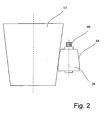
- Fig. 2 shows in a view from above a section of the rotor shaft 12.
- the rotor shaft 12 in this case has a conical shape.
- the friction roller 34 On the rotor shaft 12 is the friction roller 34, which has a conical and slightly convex lateral surface 44.
- the friction roller 34 is made of or coated with an elastomeric material having a high static friction with the rotor shaft 12. We propelled the friction roller 34 by an electric motor 46, which is held on the lever 32 (not shown).
- the drives of the friction rollers 28, 34 can be jointly controlled centrally to a rotational movement in the same direction, so that the rotor shaft 12 controlled in a suitable position for locking the rotor shaft position can be rotated.
Landscapes
- Engineering & Computer Science (AREA)
- Life Sciences & Earth Sciences (AREA)
- Sustainable Development (AREA)
- Sustainable Energy (AREA)
- Chemical & Material Sciences (AREA)
- Combustion & Propulsion (AREA)
- Mechanical Engineering (AREA)
- General Engineering & Computer Science (AREA)
- Wind Motors (AREA)
Abstract
Description
- Die vorliegende Erfindung betrifft eine Vorrichtung und ein Verfahren zum Drehen einer Rotorwelle einer Windenergieanlage.
- Bei Windenergieanlagen ist es erforderlich, für Arbeiten am Triebstrang der Windenergieanlage die Rotorwelle zu arretieren. Hierzu ist es notwendig, vor Beginn der Arbeiten am Triebstrang den Rotor der Windenergieanlage in eine definierte Position zu verstellen, damit der Triebstrang arretiert werden kann. Bei einem blockierten Getriebe kann der Rotor der Windenergieanlage nicht in die zur Arretierung vorgesehenen Positionen gebracht werden. Eine Arretierung des Rotors in einer beliebigen anderen Position ist in der Regel nicht möglich, so dass Arbeiten am Triebstrang aufgrund des blockierten Getriebes unzulässig werden. Es ist bekannt, einen Getriebetausch am Boden vorzunehmen. Hierzu wird der Rotor von der Windenergieanlage entfernt, der Triebstrang in der Gondel demontiert und mit Hilfe eines Krans auf den Boden herabgelassen. Wenn der Triebstrang am Boden ist, kann das Getriebe getauscht werden. Anschließend wird der Triebstrang wieder in die Anlage eingesetzt. Alternativ ist es möglich eine Rotorhaltevorrichtung einzusetzen, um ein defektes Getriebe auf der Anlage zu tauschen ohne den Rotor zu demontieren. Hierzu wird der Rotor in der Y- oder in der umgekehrten Y- Position arretiert. Die Rotorhaltevorrichtung nimmt die Kräfte der Rotorwelle auf und leitet sie in einen Maschinenträger der Windenergieanlage ein. Die Rotorhaltevorrichtung übernimmt für die Zeitdauer des Getriebetausches temporär die Lagerfunktion des zu entfernenden Getriebes.
- Aus
DE 10 2008 038 128 A1 ist eine Verstelleinrichtung zum Verstellen der Drehwinkelposition des Rotors einer Windenergieanlage bekannt. Hierzu wird ein Kraftübertragungsrad auf die Rotorwelle montiert und beispielsweise über eine Kette oder einen Zahnriemen mit einem Antriebsrad zum Drehen der Rotorwelle verbunden. - Aus
EP 1 659 286 B1 ist eine Törn-Vorrichtung zum Drehen des Antriebsstrangs einer Windenergieanlage bekannt. Die Törn-Vorrichtung besitzt eine am Maschinenrahmen festsetzbare Konsole, die mit einem Linearstellglied winkelbeweglich verbunden ist. Über eine auf der Rotorwelle vorgesehene Adapterscheibe kann mit Hilfe des Linearstellglieds eine Törnbewegung der Rotorwelle bewirkt werden. - Aus
DE 100 31 473 C1 ist eine Vorrichtung zum Drehen einer mit einem Rotor verbundenen oder gekoppelten Welle einer Windenergieanlage bekannt. Zum Drehen der Antriebswelle wird ein Ritzel auf der Antriebswelle befestigt und mit Hilfe eines ortsfest angebrachten Werkzeugs gedreht. - Der Erfindung liegt die Aufgabe zugrunde, eine einfach zu montierende Vorrichtung und ein Verfahren zum Drehen einer Rotorwelle einer Windenergieanlage bereitzustellen, durch die bzw. das eine Rotorwelle zuverlässig in eine gewünschte Position gedreht werden kann.
- Erfindungsgemäß wird die Aufgabe durch eine Vorrichtung mit den Merkmalen aus Anspruch 1 und ein Verfahren mit den Merkmalen aus Anspruch 11 gelöst. Vorteilhafte Ausgestaltungen bilden die Gegenstände der Unteransprüche.
- Die erfindungsgemäße Vorrichtung ist vorgesehen und bestimmt, um eine Rotorwelle einer Windenergieanlage zu drehen. Die Vorrichtung weist einen Träger, eine Verstelleinrichtung und mindestens zwei antreibbare Reibrollen auf. Der Träger ist mit Befestigungsmitteln zur ortsfesten Anbringung in einer die Rotorwelle überspannenden Position ausgestattet. In der die Rotorwelle überspannenden Position kann der Träger sowohl oberhalb als auch unterhalb der Rotorwelle angeordnet sein. Die Verstelleinrichtung ist an dem Träger gehalten und stellt den Abstand zwischen den mindestens zwei antreibbaren Reibrollen ein. Erfindungsgemäß sind die mindestens zwei Reibrollen in der montierten Position des Trägers über die Verstelleinrichtung an die Rotorwelle anpressbar und im gleichen Drehsinn antreibbar, um die Rotorwelle zu drehen. In dieser Position der Verstelleinrichtung wird der Abstand zwischen den mindestens zwei Reibrollen durch die Verstelleinrichtung vermindert. Die zwischen den Reibrollen angeordnete Rotorwelle begrenzt die Bewegung der Reibrollen, so dass die Reibrollen über eine von der Verstelleinrichtung aufgebrachte Kraft an der Rotorwelle anliegen. Durch die gleichsinnige Drehbewegung der Reibrollen wird die Rotorwelle in Bewegung gesetzt. Die erfindungsgemäße Vorrichtung kann auch bei einem blockierten Getriebe in einer die Rotorwelle überspannenden Position montiert werden. Nach dem Lösen der Verbindung zwischen Rotorwelle und Getriebe kann die Rotorwelle in eine vorbestimmte Position dreht werden, um diese zu arretieren, wobei die Rotorwelle weiterhin durch das Getriebe abgestützt wird.
- In einer bevorzugten Ausgestaltung weist jede der Reibrollen einen elektrischen Antrieb auf, über den die Reibrolle gedreht wird. Alternativ kann auch ein hydraulischer oder andersartiger Antrieb verwendet werden.
- Die Verstelleinrichtung ist bevorzugt als ein hydraulischer Hubzylinder ausgebildet. Ein hydraulischer Hubzylinder erlaubt es, eine ausreichende Anpresskraft für die Reibrollen aufzubringen, um die Rotorwelle zu drehen. Die Verstelleinrichtung kann aber auch als ein in seiner Länge verstellbares Spindelelement oder als ein Linearantrieb ausgeführt sein.
- In einer bevorzugten Ausgestaltung sind eine erste Reibrolle mit einem ersten Ende der Verstelleinrichtung und eine zweite Reibrolle mit einem zweiten Ende der Verstelleinrichtung verbunden und wirken mit dieser zusammen. In dieser Ausgestaltung wird die Längenänderung der Verstelleinrichtung in eine Abstandsänderung zwischen den Reibrollen umgesetzt. Bevorzugt wird hierbei die erste und zweite Reibrolle jeweils über einen schwenkbar mit dem Träger verbundenen Hebel mit der Verstelleinrichtung verbunden. Über den Hebel wird eine Verlängerung der Verstelleinrichtung in eine Bewegung der Reibrollen aufeinander zu umgesetzt, wodurch sich der Abstand zwischen den Reibrollen verringert. Durch eine Verkürzung der Verstelleinrichtung wird der Abstand zwischen den Reibrollen vergrößert.
- Um die Kraft von den Reibrollen auf die Rotorwelle zu übertragen, ist bevorzugt jede der Reibrollen mit einem den Reibwert vergrößernden Belag oder mit einer entsprechenden Oberflächenstruktur versehen.
- In einer bevorzugten Ausgestaltung besitzen die Reibrollen entsprechend der Ausbildung der Rotorwelle eine zylindrische oder konische Gestalt, bevorzugt mit einer leicht balligen Oberfläche, wodurch die Reibrollen in ihrem montierten Zustand flächig mit ihrer Mantelfläche an der Rotorwelle anliegen können. Die flächige Anlage stellt sicher, dass eine große Kraft zwischen den Reibrollen und der Rotorwelle übertragen werden kann.
- In einer weiteren Ausgestaltung ist die Anpresskraft der Reibrollen an der Rotorwelle so gewählt, dass die Rotorwelle bei kurzzeitigen Überlasten durch Windböen zwischen den Reibrollen rutschen kann. Dadurch wird ein Überlastschutz gewährleistet. Das Durchrutschen der Rotorwelle zwischen den Reibrollen wird durch die Auswahl eines geeigneten Materials für den Belag oder die Oberfläche der Reibrollen erzielt.
- Die oben genannte Aufgabe wird ebenfalls gelöst durch ein Verfahren mit den Merkmalen des Anspruchs 11.
- Durch das erfindungsgemäße Verfahren kann eine Rotorwelle einer Windenergieanlage in eine gewünschte Position gedreht werden. Es weist die folgenden Schritte auf:
- Montieren eines Trägers mit einer Verstelleinrichtung und mindestens zweier Reibrollen auf einem Maschinenträger einer Windenergieanlage in einer die Rotorwelle überspannenden Position,
- Anpressen der Reibrollen an die Rotorwelle durch ein Betätigen der Verstelleinrichtung, und
- Antreiben der Reibrollen im gleichen Drehsinn zur Erzeugung einer Drehbewegung der Rotorwelle.
- Ein Träger mit einer Verstelleinrichtung und mindestens zwei Reibrollen wird auf einem Maschinenträger einer Windenergieanlage montiert. Der Maschinenträger ist dabei das Teil der Windenergieanlage, das den Triebstrang trägt und auf welchem die Rotorwelle und das Getriebe gelagert sind. Der Träger überspannt hierbei die Rotorwelle. Die mit der Verstelleinrichtung verbundenen Reibrollen werden auf beiden Seiten der Rotorwelle positioniert und durch ein Betätigen der Verstelleinrichtung an die Rotorwelle angepresst. Die Reibrollen werden im gleichen Drehsinn angetrieben, wodurch die Rotorwelle in eine Drehbewegung versetzt wird.
- In einer besonderen Ausgestaltung wird das Verfahren zum Drehen einer Rotorwelle einer Windenergieanlage verwendet, welche mit einem blockierten Getriebe verbunden ist. Hierbei wird nach dem Anpressen der Reibrollen die Verbindung der Rotorwelle mit dem Getriebe gelöst. Bei einer Lagerung der Rotorwelle in dem Getriebe kann die Rotorwelle auch bei gelöster Verbindung weiterhin im Getriebe abgestützt sein. Die Rotorwelle wird dann relativ zu einer Getriebeeingangswelle drehbar abgestützt. Die gleichsinnig angetriebenen Reibrollen drehen die Rotorwelle in eine Position, in der der Rotor arretiert werden kann. Zur Demontage des Getriebes wird eine bekannte Rotorhaltevorrichtung verwendet.
- Eine bevorzugte Ausgestaltung der Erfindung wird nachfolgend näher erläutert. Es zeigt:
- Fig. 1
- einen schematischen Querschnitt durch die Rotorwelle und
- Fig. 2
- eine schematische Draufsicht auf die Rotorwelle.
-
Fig. 1 zeigt einen Querschnitt durch einen Maschinenträger 10. Der Maschinenträger 10 ist an einer Gondel der Windenergieanlage angeordnet und trägt eine Rotorwelle 12, mit der eine Drehbewegung des Rotors an ein Getriebe oder einen Generator weitergeleitet wird. Der Maschinenträger 10 ist in der Regel als ein massives Gussteil oder eine entsprechend stabile Rahmenkonstruktion ausgebildet. Die Rotorwelle 12 ist in der Regel rotorseitig durch ein Lager (nicht dargestellt) auf den Maschinenträger 10 gestützt und mündet in einem Getriebe oder einem Generator (nicht dargestellt). - Um die Rotorwelle bei einem Getriebeschaden mit blockiertem Getriebe drehen zu können, muss die Rotorwelle von dem Getriebe entkoppelt werden. Dies kann beispielsweise durch das Öffnen eines Spannsatzes am Getriebe geschehen.
- Um die Drehbewegung der Rotorwelle bei einem entkoppelten Getriebe kontrollieren zu können, wird ein Träger 14 mit seinen Enden 16 auf den Maschinenträger 10 montiert. Der Träger 14 weist eine die Rotorwelle überspannende Traverse 18 auf, die sich über die Rotorwelle erstreckt. Die Enden des Trägers 14 können beispielsweise mit Flanschen versehen sein, über die der Träger lösbar mit dem Maschinenträger 10 verschraubt ist. An der Traverse 18 des Trägers 14 ist eine Verstelleinrichtung 20 in Form eines Hubzylinders angeordnet. Der Hubzylinder 20 besitzt ein Zylindergehäuse 22 und eine Kolbenstange 24. Die Längsrichtung der Kolbenstange 24 erstreckt sich im Wesentlichen parallel zu der Traverse 18 des Trägers 14. Das Zylindergehäuse 22 ist über eine Hebelstange 26 mit einer Reibrolle 28 verbunden. Die Hebelstange 26 ist mit der Traverse 18 in einem Gelenk 30 schwenkbar gelagert. Entsprechend ist mit der Kolbenstange 24 ein Hebel 32 verbunden, der mit der Reibrolle 28 in Verbindung steht. Der Hebel 32 ist an einem Gelenk 36 schwenkbar an der Traverse 18 angebracht.
- Durch ein Ausfahren der Kolbenstange 24 in Richtung A verschwenken die erste Hebelstange 26 und die zweite Hebelstange 32 um ihre Gelenke 30 und 36, so dass sich die Rollen 28 und 34 aufeinander zu bewegen.
- Wenn der Träger 14 oberhalb der Rotorwelle montiert ist, entsteht durch die Verlängerung des Hubzylinders 18 eine Anpresskraft F der Reibrollen 28 und 34 gegen die Rotorwelle 12.
- Die Gelenke 30 und 36 besitzen den gleichen Abstand d von einem gedachten Mittelpunkt 37, der oberhalb des Mittelpunktes 38 der Rotorwelle 12 liegt. Auf diese Weise wird sichergestellt, dass die aus der Längenänderung des Hubzylinders erzeugte Anpresskraft F für beide Reibrollen 28, 34 gleich groß ist und so ein Schlupf zwischen der Rotorwelle 12 und den Reibrollen 28, 34 vermieden wird.
- Wie in
Fig. 1 zu erkennen, sind die Reibrollen 28 und 34 auf einer Höhe relativ zu der Rotorwelle angeordnet. In der dargestellten Anordnung liegen die Mittelpunkte 40 und 42 der Reibrollen 28 bzw. 34 auf einer Geraden mit dem Mittelpunkt 38 der Rotorwelle 12. Neben der dargestellten Anordnung, in der die Mittelpunkte 38, 40 und 42 auf einer Geraden liegen, ist es auch möglich, die Reibrollen 28 und 34 in einer anderen Winkelposition gegenüber der Rotorwelle 12 anzuordnen, so dass beispielsweise die Verbindung der Mittelpunkte 40, 38, 42 ein V bildet. - Die Reibrollen 28 und 34 besitzen jeweils einen eigenen elektrischen Antrieb, um die Reibrollen zu drehen. Die Drehung der Reibrollen erfolgt gleichsinnig, so dass insgesamt eine Drehbewegung der Rotorwelle 12 entsteht.
- Bezogen auf die Verwendung der Erfindung bei einem Getriebeschaden, werden vor einem Lösen der Verbindung zwischen Rotorwelle 12 und Getriebe die Reibrollen 28, 34 über den Träger angesetzt und durch ein Betätigen des Hubzylinders gegen die Rotorwelle gepresst. Bei stehenden Antrieben der Reibrollen kann nun die Verbindung zum Getriebe gelöst werden. Ein unkontrolliertes Drehen der Rotorwelle wird durch die Reibrollen verhindert. Sollte es dennoch aufgrund einer Windböe oder aufgrund anderer Umstände zu einem angreifenden Drehmoment an der Rotorwelle 12 kommen, kann dieses bis zu einer bestimmten Stärke durch die angepressten Reibrollen aufgefangen werden. Ist das angreifende Drehmoment zu stark, beginnt die Rotorwelle sich gleitend gegen die Anpresskraft der Reibrollen und deren Haltemoment zu drehen. Auf diese Weise ist ein Überlastschutz sichergestellt.
- Durch Betätigung der Reibrollen 28, 34 in gleichsinniger Drehrichtung kann die Rotorwelle 12 kontrolliert in eine gewünschte Arretierposition gedreht werden. In der Regel handelt es sich hierbei um eine Y- oder eine umgekehrte Y-Position der Rotorblätter.
-
Fig. 2 zeigt in einer Ansicht von oben einen Ausschnitt der Rotorwelle 12. Die Rotorwelle 12 besitzt hierbei einen konischen Verlauf. An der Rotorwelle 12 liegt die Reibrolle 34 an, die eine konische und leicht ballige Mantelfläche 44 besitzt. Die Reibrolle 34 ist aus einem Elastomermaterial hergestellt oder damit beschichtet, das eine hohe Haftreibung mit der Rotorwelle 12 besitzt. Angetrieben wir die Reibrolle 34 von einem Elektromotor 46, der an dem Hebel 32 (nicht dargestellt) gehalten ist. - Die Antriebe der Reibrollen 28, 34 können gemeinsam zentral zu einer gleichsinnigen Drehbewegung angesteuert werden, so dass die Rotorwelle 12 kontrolliert in eine zur Arretierung der Rotorwelle geeignete Position gedreht werden kann.
Claims (12)
- Vorrichtung zum Drehen einer Rotorwelle einer Windenergieanlage mit- einem Träger (14), der Befestigungsmittel (16) zur ortsfesten Anbringung in einer die Rotorwelle (12) überspannenden Position aufweist,- einer Verstelleinrichtung (20), die an dem Träger (14) gehalten ist, und- mindestens zwei antreibbaren Reibrollen (28, 34), deren Abstand zueinander über die Verstelleinrichtung (20) einstellbar ist,- wobei in der montierten Position des Trägers (14) mindestens zwei Reibrollen über die Verstelleinrichtung (20) an die Rotorwelle (12) anpressbar und gleichsinnig antreibbar sind, um die Rotorwelle (12) zu drehen.
- Vorrichtung nach Anspruch 1, dadurch gekennzeichnet, dass jede Reibrolle über einen elektrischen oder einen hydraulischen Antrieb (46) verfügt.
- Vorrichtung nach Anspruch 1 oder 2, dadurch gekennzeichnet, dass die Verstelleinrichtung (20) als ein hydraulischer Hubzylinder ausgebildet ist.
- Vorrichtung nach Anspruch 1 oder 2, dadurch gekennzeichnet, dass die Verstelleinrichtung (20) als Linearantrieb ausgebildet ist.
- Vorrichtung nach einem der Ansprüche 1 bis 4, dadurch gekennzeichnet, dass eine erste Reibrolle (28) mit einem ersten Ende (22) der Verstelleinrichtung (20) und eine zweite Reibrolle (34) mit einem zweiten Ende (24) der Verstelleinrichtung (20) zusammenwirkt.
- Vorrichtung nach Anspruch 5, dadurch gekennzeichnet, dass die erste und zweite Reibrolle jeweils über einen schwenkbar mit dem Träger verbundenen Hebel (26, 32) mit der Verstelleinrichtung (20) verbunden ist.
- Vorrichtung nach einem der Ansprüche 1 bis 6, dadurch gekennzeichnet, dass jede der Reibrollen (28, 34) einen den Reibwert erhöhenden Belag besitzt.
- Vorrichtung nach einem der Ansprüche 1 bis 7, dadurch gekennzeichnet, dass die Reibrollen (28, 34) eine zylindrische oder konische Gestalt aufweisen.
- Vorrichtung nach Anspruch 8, dadurch gekennzeichnet, dass die Reibrollen in ihrer montierten Position flächig mit ihrer Mantelfläche (44) an der Rotorwelle (12) anliegen.
- Vorrichtung nach einem der Ansprüche 1 bis 9, dadurch gekennzeichnet, dass die Rotorwelle bei Überlasten zwischen den Reibrollen rutscht.
- Verfahren zum Drehen einer Rotorwelle (12) einer Windenergieanlage mit folgenden Schritten- Montieren eines Trägers (14) mit einer Verstelleinrichtung (20) und mind. zwei Reibrollen (28, 34) auf einem Maschinenträger (10) in einer die Rotorwelle (12) überspannenden Position,- Anpressen der Reibrollen (28, 34) an die Rotorwelle (12) durch ein Betätigen der Verstelleinrichtung (20),- Antreiben der Reibrollen (28, 34) im gleichen Drehsinn zur Erzeugung einer Drehbewegung der Rotorwelle (12).
- Verfahren zum Drehen einer Rotorwelle (12) einer Windenergieanlage, dadurch gekennzeichnet, dass nach dem Anpressen der Reibrollen (28, 34) die Verbindung der Rotorwelle (12) mit einem Getriebe gelöst wird.
Applications Claiming Priority (1)
| Application Number | Priority Date | Filing Date | Title |
|---|---|---|---|
| DE102011106428A DE102011106428B3 (de) | 2011-07-02 | 2011-07-02 | Vorrichtung und Verfahren zum Drehen einer Rotorwelle einer Windenergieanlage |
Publications (3)
| Publication Number | Publication Date |
|---|---|
| EP2543878A2 true EP2543878A2 (de) | 2013-01-09 |
| EP2543878A3 EP2543878A3 (de) | 2017-03-15 |
| EP2543878B1 EP2543878B1 (de) | 2018-08-01 |
Family
ID=46458098
Family Applications (1)
| Application Number | Title | Priority Date | Filing Date |
|---|---|---|---|
| EP12004472.2A Not-in-force EP2543878B1 (de) | 2011-07-02 | 2012-06-13 | Vorrichtung und Verfahren zum Drehen einer Rotorwelle einer Windenergieanlage |
Country Status (4)
| Country | Link |
|---|---|
| EP (1) | EP2543878B1 (de) |
| DE (1) | DE102011106428B3 (de) |
| DK (1) | DK2543878T3 (de) |
| ES (1) | ES2693644T3 (de) |
Citations (3)
| Publication number | Priority date | Publication date | Assignee | Title |
|---|---|---|---|---|
| DE10031473C1 (de) | 2000-06-28 | 2002-02-28 | Tacke Windenergie Gmbh | Vorrichtung zum Drehen einer mit einem Rotor verbundenen oder gekoppelten Welle einer Windkraftanlage |
| EP1659286B1 (de) | 2004-11-18 | 2008-08-20 | Eickhoff Maschinenfabrik GmbH | Törn-Vorrichtung zum Drehen des Antriebsstranges einer Windkraftanlage |
| DE102008038128A1 (de) | 2008-08-18 | 2010-02-25 | Kenersys Gmbh | Verstelleinrichtung zum Verstellen der Drehwinkelposition des Rotors einer Windenergieanlage |
Family Cites Families (2)
| Publication number | Priority date | Publication date | Assignee | Title |
|---|---|---|---|---|
| DE1276655B (de) * | 1960-10-19 | 1968-09-05 | Licentia Gmbh | Turbinenwellen-Drehvorrichtung mit Stirnreibraeder-Getriebe |
| DE2747891A1 (de) * | 1977-10-26 | 1979-05-10 | Ass Elect Ind | Mechanismus und verfahren zum abstuetzen und schrittweisen drehen eines drehteils |
-
2011
- 2011-07-02 DE DE102011106428A patent/DE102011106428B3/de not_active Expired - Fee Related
-
2012
- 2012-06-13 EP EP12004472.2A patent/EP2543878B1/de not_active Not-in-force
- 2012-06-13 ES ES12004472.2T patent/ES2693644T3/es active Active
- 2012-06-13 DK DK12004472.2T patent/DK2543878T3/en active
Patent Citations (3)
| Publication number | Priority date | Publication date | Assignee | Title |
|---|---|---|---|---|
| DE10031473C1 (de) | 2000-06-28 | 2002-02-28 | Tacke Windenergie Gmbh | Vorrichtung zum Drehen einer mit einem Rotor verbundenen oder gekoppelten Welle einer Windkraftanlage |
| EP1659286B1 (de) | 2004-11-18 | 2008-08-20 | Eickhoff Maschinenfabrik GmbH | Törn-Vorrichtung zum Drehen des Antriebsstranges einer Windkraftanlage |
| DE102008038128A1 (de) | 2008-08-18 | 2010-02-25 | Kenersys Gmbh | Verstelleinrichtung zum Verstellen der Drehwinkelposition des Rotors einer Windenergieanlage |
Also Published As
| Publication number | Publication date |
|---|---|
| DK2543878T3 (en) | 2018-11-19 |
| DE102011106428B3 (de) | 2012-10-25 |
| EP2543878B1 (de) | 2018-08-01 |
| ES2693644T3 (es) | 2018-12-13 |
| EP2543878A3 (de) | 2017-03-15 |
Similar Documents
| Publication | Publication Date | Title |
|---|---|---|
| EP2280191B2 (de) | Antriebseinheit mit Überlastschutz zum Antrieb eines Zahnkranzes, Set aus mehreren derartigen Antriebseinheiten sowie Vorrichtung enthaltend eine derartige Antriebseinheit | |
| EP3942189B1 (de) | Gleitlagerung | |
| DE3111583C2 (de) | ||
| EP1794449B1 (de) | Verfahren zum betreiben einer vorrichtung zum verstellen eines blatteinstellwinkels sowie eine verstellvorrichtung | |
| EP1955976A1 (de) | Windenvorrichtung | |
| EP1882852A1 (de) | Windenergieanlage mit einem Maschinenhaus | |
| EP2260206A2 (de) | Vorrichtung zur verstellung des anstellwinkels eines rotorblattes einer windenergieanlage | |
| EP2616714A1 (de) | Demontage eines getriebes einer windenergieanlage | |
| EP1266137A1 (de) | Lagerung eines verstellbaren rotorblatts einer windenergieanlage | |
| DE102010020355B4 (de) | Arretiervorrichtung für einen Triebstrang einer Windenergieanlage | |
| AT524486A1 (de) | Verfahren zum Wechseln von an einer Rotorwelle einer Rotorlagerung einer Windkraftanlage angeordneten Gleitlagerpads | |
| EP0453868B1 (de) | Vorrichtung zum Verstellen der Falzklappen an einem Falzklappenzylinder | |
| WO2008148526A2 (de) | Lageranordnung für eine windturbine | |
| DE102023115292A1 (de) | Aktor zur Bereitstellung eines Drehmoments mit einem Linearantrieb | |
| DE3722022C1 (en) | Actuator | |
| AT507636A1 (de) | Vorrichtung zum übertragen eines drehmoments auf einen drehrohrofen | |
| WO2010045914A2 (de) | Lageveränderlicher pitch-antrieb | |
| EP2851522A1 (de) | Drehvorrichtung für eine Gasturbine und Verfahren zum Drehen eines Bauteils | |
| EP4291790B1 (de) | Antriebs- und/oder verstellvorrichtung mit überlastschutz | |
| DE102010039778B4 (de) | Rotorblatt für Windenergieanlagen | |
| EP2620636B1 (de) | Arretiervorrichtung für einen Triebstrang einer Windenergieanlage | |
| DE3117996C2 (de) | ||
| DE102011106428B3 (de) | Vorrichtung und Verfahren zum Drehen einer Rotorwelle einer Windenergieanlage | |
| EP1099502A1 (de) | Hochgeschwindigkeitsschere zum Querteilen von insbesondere dünnem Walzband | |
| DE20115350U1 (de) | Drehverbindung |
Legal Events
| Date | Code | Title | Description |
|---|---|---|---|
| PUAI | Public reference made under article 153(3) epc to a published international application that has entered the european phase |
Free format text: ORIGINAL CODE: 0009012 |
|
| AK | Designated contracting states |
Kind code of ref document: A2 Designated state(s): AL AT BE BG CH CY CZ DE DK EE ES FI FR GB GR HR HU IE IS IT LI LT LU LV MC MK MT NL NO PL PT RO RS SE SI SK SM TR |
|
| AX | Request for extension of the european patent |
Extension state: BA ME |
|
| PUAL | Search report despatched |
Free format text: ORIGINAL CODE: 0009013 |
|
| AK | Designated contracting states |
Kind code of ref document: A3 Designated state(s): AL AT BE BG CH CY CZ DE DK EE ES FI FR GB GR HR HU IE IS IT LI LT LU LV MC MK MT NL NO PL PT RO RS SE SI SK SM TR |
|
| AX | Request for extension of the european patent |
Extension state: BA ME |
|
| RIC1 | Information provided on ipc code assigned before grant |
Ipc: F03D 11/00 00000000AFI20170209BHEP Ipc: F03D 7/02 20060101ALI20170209BHEP |
|
| STAA | Information on the status of an ep patent application or granted ep patent |
Free format text: STATUS: REQUEST FOR EXAMINATION WAS MADE |
|
| 17P | Request for examination filed |
Effective date: 20170726 |
|
| RBV | Designated contracting states (corrected) |
Designated state(s): AL AT BE BG CH CY CZ DE DK EE ES FI FR GB GR HR HU IE IS IT LI LT LU LV MC MK MT NL NO PL PT RO RS SE SI SK SM TR |
|
| REG | Reference to a national code |
Ref country code: DE Ref legal event code: R079 Ref document number: 502012013133 Country of ref document: DE Free format text: PREVIOUS MAIN CLASS: F03D0011000000 Ipc: F03D0080000000 |
|
| RIC1 | Information provided on ipc code assigned before grant |
Ipc: F03D 80/50 20160101ALI20171201BHEP Ipc: F03D 80/00 20160101AFI20171201BHEP |
|
| GRAP | Despatch of communication of intention to grant a patent |
Free format text: ORIGINAL CODE: EPIDOSNIGR1 |
|
| STAA | Information on the status of an ep patent application or granted ep patent |
Free format text: STATUS: GRANT OF PATENT IS INTENDED |
|
| INTG | Intention to grant announced |
Effective date: 20180124 |
|
| GRAS | Grant fee paid |
Free format text: ORIGINAL CODE: EPIDOSNIGR3 |
|
| GRAA | (expected) grant |
Free format text: ORIGINAL CODE: 0009210 |
|
| STAA | Information on the status of an ep patent application or granted ep patent |
Free format text: STATUS: THE PATENT HAS BEEN GRANTED |
|
| AK | Designated contracting states |
Kind code of ref document: B1 Designated state(s): AL AT BE BG CH CY CZ DE DK EE ES FI FR GB GR HR HU IE IS IT LI LT LU LV MC MK MT NL NO PL PT RO RS SE SI SK SM TR |
|
| REG | Reference to a national code |
Ref country code: GB Ref legal event code: FG4D Free format text: NOT ENGLISH |
|
| REG | Reference to a national code |
Ref country code: CH Ref legal event code: EP Ref country code: AT Ref legal event code: REF Ref document number: 1024615 Country of ref document: AT Kind code of ref document: T Effective date: 20180815 |
|
| REG | Reference to a national code |
Ref country code: IE Ref legal event code: FG4D Free format text: LANGUAGE OF EP DOCUMENT: GERMAN |
|
| REG | Reference to a national code |
Ref country code: DE Ref legal event code: R096 Ref document number: 502012013133 Country of ref document: DE |
|
| REG | Reference to a national code |
Ref country code: DK Ref legal event code: T3 Effective date: 20181115 |
|
| REG | Reference to a national code |
Ref country code: NL Ref legal event code: MP Effective date: 20180801 |
|
| REG | Reference to a national code |
Ref country code: ES Ref legal event code: FG2A Ref document number: 2693644 Country of ref document: ES Kind code of ref document: T3 Effective date: 20181213 |
|
| REG | Reference to a national code |
Ref country code: LT Ref legal event code: MG4D |
|
| PG25 | Lapsed in a contracting state [announced via postgrant information from national office to epo] |
Ref country code: BG Free format text: LAPSE BECAUSE OF FAILURE TO SUBMIT A TRANSLATION OF THE DESCRIPTION OR TO PAY THE FEE WITHIN THE PRESCRIBED TIME-LIMIT Effective date: 20181101 Ref country code: NL Free format text: LAPSE BECAUSE OF FAILURE TO SUBMIT A TRANSLATION OF THE DESCRIPTION OR TO PAY THE FEE WITHIN THE PRESCRIBED TIME-LIMIT Effective date: 20180801 Ref country code: LT Free format text: LAPSE BECAUSE OF FAILURE TO SUBMIT A TRANSLATION OF THE DESCRIPTION OR TO PAY THE FEE WITHIN THE PRESCRIBED TIME-LIMIT Effective date: 20180801 Ref country code: PL Free format text: LAPSE BECAUSE OF FAILURE TO SUBMIT A TRANSLATION OF THE DESCRIPTION OR TO PAY THE FEE WITHIN THE PRESCRIBED TIME-LIMIT Effective date: 20180801 Ref country code: IS Free format text: LAPSE BECAUSE OF FAILURE TO SUBMIT A TRANSLATION OF THE DESCRIPTION OR TO PAY THE FEE WITHIN THE PRESCRIBED TIME-LIMIT Effective date: 20181201 Ref country code: SE Free format text: LAPSE BECAUSE OF FAILURE TO SUBMIT A TRANSLATION OF THE DESCRIPTION OR TO PAY THE FEE WITHIN THE PRESCRIBED TIME-LIMIT Effective date: 20180801 Ref country code: NO Free format text: LAPSE BECAUSE OF FAILURE TO SUBMIT A TRANSLATION OF THE DESCRIPTION OR TO PAY THE FEE WITHIN THE PRESCRIBED TIME-LIMIT Effective date: 20181101 Ref country code: FI Free format text: LAPSE BECAUSE OF FAILURE TO SUBMIT A TRANSLATION OF THE DESCRIPTION OR TO PAY THE FEE WITHIN THE PRESCRIBED TIME-LIMIT Effective date: 20180801 Ref country code: GR Free format text: LAPSE BECAUSE OF FAILURE TO SUBMIT A TRANSLATION OF THE DESCRIPTION OR TO PAY THE FEE WITHIN THE PRESCRIBED TIME-LIMIT Effective date: 20181102 Ref country code: RS Free format text: LAPSE BECAUSE OF FAILURE TO SUBMIT A TRANSLATION OF THE DESCRIPTION OR TO PAY THE FEE WITHIN THE PRESCRIBED TIME-LIMIT Effective date: 20180801 |
|
| REG | Reference to a national code |
Ref country code: CH Ref legal event code: PK Free format text: BERICHTIGUNGEN |
|
| RIC2 | Information provided on ipc code assigned after grant |
Ipc: F03D 80/50 20160101ALI20171201BHEP Ipc: F03D 80/00 20160101AFI20171201BHEP |
|
| PG25 | Lapsed in a contracting state [announced via postgrant information from national office to epo] |
Ref country code: HR Free format text: LAPSE BECAUSE OF FAILURE TO SUBMIT A TRANSLATION OF THE DESCRIPTION OR TO PAY THE FEE WITHIN THE PRESCRIBED TIME-LIMIT Effective date: 20180801 Ref country code: LV Free format text: LAPSE BECAUSE OF FAILURE TO SUBMIT A TRANSLATION OF THE DESCRIPTION OR TO PAY THE FEE WITHIN THE PRESCRIBED TIME-LIMIT Effective date: 20180801 Ref country code: AL Free format text: LAPSE BECAUSE OF FAILURE TO SUBMIT A TRANSLATION OF THE DESCRIPTION OR TO PAY THE FEE WITHIN THE PRESCRIBED TIME-LIMIT Effective date: 20180801 |
|
| PG25 | Lapsed in a contracting state [announced via postgrant information from national office to epo] |
Ref country code: EE Free format text: LAPSE BECAUSE OF FAILURE TO SUBMIT A TRANSLATION OF THE DESCRIPTION OR TO PAY THE FEE WITHIN THE PRESCRIBED TIME-LIMIT Effective date: 20180801 Ref country code: IT Free format text: LAPSE BECAUSE OF FAILURE TO SUBMIT A TRANSLATION OF THE DESCRIPTION OR TO PAY THE FEE WITHIN THE PRESCRIBED TIME-LIMIT Effective date: 20180801 Ref country code: CZ Free format text: LAPSE BECAUSE OF FAILURE TO SUBMIT A TRANSLATION OF THE DESCRIPTION OR TO PAY THE FEE WITHIN THE PRESCRIBED TIME-LIMIT Effective date: 20180801 Ref country code: RO Free format text: LAPSE BECAUSE OF FAILURE TO SUBMIT A TRANSLATION OF THE DESCRIPTION OR TO PAY THE FEE WITHIN THE PRESCRIBED TIME-LIMIT Effective date: 20180801 |
|
| REG | Reference to a national code |
Ref country code: DE Ref legal event code: R097 Ref document number: 502012013133 Country of ref document: DE |
|
| PG25 | Lapsed in a contracting state [announced via postgrant information from national office to epo] |
Ref country code: SK Free format text: LAPSE BECAUSE OF FAILURE TO SUBMIT A TRANSLATION OF THE DESCRIPTION OR TO PAY THE FEE WITHIN THE PRESCRIBED TIME-LIMIT Effective date: 20180801 Ref country code: SM Free format text: LAPSE BECAUSE OF FAILURE TO SUBMIT A TRANSLATION OF THE DESCRIPTION OR TO PAY THE FEE WITHIN THE PRESCRIBED TIME-LIMIT Effective date: 20180801 |
|
| PLBE | No opposition filed within time limit |
Free format text: ORIGINAL CODE: 0009261 |
|
| STAA | Information on the status of an ep patent application or granted ep patent |
Free format text: STATUS: NO OPPOSITION FILED WITHIN TIME LIMIT |
|
| 26N | No opposition filed |
Effective date: 20190503 |
|
| PG25 | Lapsed in a contracting state [announced via postgrant information from national office to epo] |
Ref country code: SI Free format text: LAPSE BECAUSE OF FAILURE TO SUBMIT A TRANSLATION OF THE DESCRIPTION OR TO PAY THE FEE WITHIN THE PRESCRIBED TIME-LIMIT Effective date: 20180801 |
|
| REG | Reference to a national code |
Ref country code: DE Ref legal event code: R119 Ref document number: 502012013133 Country of ref document: DE |
|
| REG | Reference to a national code |
Ref country code: DK Ref legal event code: EBP Effective date: 20190630 |
|
| PG25 | Lapsed in a contracting state [announced via postgrant information from national office to epo] |
Ref country code: MC Free format text: LAPSE BECAUSE OF FAILURE TO SUBMIT A TRANSLATION OF THE DESCRIPTION OR TO PAY THE FEE WITHIN THE PRESCRIBED TIME-LIMIT Effective date: 20180801 |
|
| REG | Reference to a national code |
Ref country code: CH Ref legal event code: PL |
|
| GBPC | Gb: european patent ceased through non-payment of renewal fee |
Effective date: 20190613 |
|
| REG | Reference to a national code |
Ref country code: BE Ref legal event code: MM Effective date: 20190630 |
|
| PG25 | Lapsed in a contracting state [announced via postgrant information from national office to epo] |
Ref country code: TR Free format text: LAPSE BECAUSE OF FAILURE TO SUBMIT A TRANSLATION OF THE DESCRIPTION OR TO PAY THE FEE WITHIN THE PRESCRIBED TIME-LIMIT Effective date: 20180801 |
|
| PG25 | Lapsed in a contracting state [announced via postgrant information from national office to epo] |
Ref country code: DE Free format text: LAPSE BECAUSE OF NON-PAYMENT OF DUE FEES Effective date: 20200101 Ref country code: IE Free format text: LAPSE BECAUSE OF NON-PAYMENT OF DUE FEES Effective date: 20190613 Ref country code: GB Free format text: LAPSE BECAUSE OF NON-PAYMENT OF DUE FEES Effective date: 20190613 |
|
| PG25 | Lapsed in a contracting state [announced via postgrant information from national office to epo] |
Ref country code: BE Free format text: LAPSE BECAUSE OF NON-PAYMENT OF DUE FEES Effective date: 20190630 Ref country code: LU Free format text: LAPSE BECAUSE OF NON-PAYMENT OF DUE FEES Effective date: 20190613 Ref country code: CH Free format text: LAPSE BECAUSE OF NON-PAYMENT OF DUE FEES Effective date: 20190630 Ref country code: LI Free format text: LAPSE BECAUSE OF NON-PAYMENT OF DUE FEES Effective date: 20190630 |
|
| PG25 | Lapsed in a contracting state [announced via postgrant information from national office to epo] |
Ref country code: FR Free format text: LAPSE BECAUSE OF NON-PAYMENT OF DUE FEES Effective date: 20190630 Ref country code: PT Free format text: LAPSE BECAUSE OF FAILURE TO SUBMIT A TRANSLATION OF THE DESCRIPTION OR TO PAY THE FEE WITHIN THE PRESCRIBED TIME-LIMIT Effective date: 20181201 |
|
| PG25 | Lapsed in a contracting state [announced via postgrant information from national office to epo] |
Ref country code: DK Free format text: LAPSE BECAUSE OF NON-PAYMENT OF DUE FEES Effective date: 20190630 |
|
| REG | Reference to a national code |
Ref country code: AT Ref legal event code: MM01 Ref document number: 1024615 Country of ref document: AT Kind code of ref document: T Effective date: 20190613 |
|
| REG | Reference to a national code |
Ref country code: ES Ref legal event code: FD2A Effective date: 20201028 |
|
| PG25 | Lapsed in a contracting state [announced via postgrant information from national office to epo] |
Ref country code: AT Free format text: LAPSE BECAUSE OF NON-PAYMENT OF DUE FEES Effective date: 20190613 |
|
| PG25 | Lapsed in a contracting state [announced via postgrant information from national office to epo] |
Ref country code: ES Free format text: LAPSE BECAUSE OF NON-PAYMENT OF DUE FEES Effective date: 20190614 |
|
| PG25 | Lapsed in a contracting state [announced via postgrant information from national office to epo] |
Ref country code: CY Free format text: LAPSE BECAUSE OF FAILURE TO SUBMIT A TRANSLATION OF THE DESCRIPTION OR TO PAY THE FEE WITHIN THE PRESCRIBED TIME-LIMIT Effective date: 20180801 |
|
| PG25 | Lapsed in a contracting state [announced via postgrant information from national office to epo] |
Ref country code: HU Free format text: LAPSE BECAUSE OF FAILURE TO SUBMIT A TRANSLATION OF THE DESCRIPTION OR TO PAY THE FEE WITHIN THE PRESCRIBED TIME-LIMIT; INVALID AB INITIO Effective date: 20120613 Ref country code: MT Free format text: LAPSE BECAUSE OF FAILURE TO SUBMIT A TRANSLATION OF THE DESCRIPTION OR TO PAY THE FEE WITHIN THE PRESCRIBED TIME-LIMIT Effective date: 20180801 |
|
| PG25 | Lapsed in a contracting state [announced via postgrant information from national office to epo] |
Ref country code: MK Free format text: LAPSE BECAUSE OF FAILURE TO SUBMIT A TRANSLATION OF THE DESCRIPTION OR TO PAY THE FEE WITHIN THE PRESCRIBED TIME-LIMIT Effective date: 20180801 |