EP2543864B1 - Antriebseinheit eines Luftfahrzeugs mit einem Hitzeschild einer hinteren Stromlinienverkleidung einer Triebwerksaufhängung sowie Kühlverfahren für das Hitzeschild - Google Patents
Antriebseinheit eines Luftfahrzeugs mit einem Hitzeschild einer hinteren Stromlinienverkleidung einer Triebwerksaufhängung sowie Kühlverfahren für das Hitzeschild Download PDFInfo
- Publication number
- EP2543864B1 EP2543864B1 EP12173763.9A EP12173763A EP2543864B1 EP 2543864 B1 EP2543864 B1 EP 2543864B1 EP 12173763 A EP12173763 A EP 12173763A EP 2543864 B1 EP2543864 B1 EP 2543864B1
- Authority
- EP
- European Patent Office
- Prior art keywords
- thermal protection
- propulsion system
- turbojet
- protection floor
- air
- Prior art date
- Legal status (The legal status is an assumption and is not a legal conclusion. Google has not performed a legal analysis and makes no representation as to the accuracy of the status listed.)
- Active
Links
- 238000001816 cooling Methods 0.000 title claims description 22
- 238000000034 method Methods 0.000 claims description 6
- 238000007789 sealing Methods 0.000 claims description 2
- 238000000605 extraction Methods 0.000 claims 3
- 238000005070 sampling Methods 0.000 description 5
- 230000015572 biosynthetic process Effects 0.000 description 4
- 230000004888 barrier function Effects 0.000 description 2
- 239000000446 fuel Substances 0.000 description 2
- 230000000630 rising effect Effects 0.000 description 2
- 238000005204 segregation Methods 0.000 description 2
- 239000000725 suspension Substances 0.000 description 2
- 210000002105 tongue Anatomy 0.000 description 2
- UJCHIZDEQZMODR-BYPYZUCNSA-N (2r)-2-acetamido-3-sulfanylpropanamide Chemical compound CC(=O)N[C@@H](CS)C(N)=O UJCHIZDEQZMODR-BYPYZUCNSA-N 0.000 description 1
- 241001669680 Dormitator maculatus Species 0.000 description 1
- 230000000712 assembly Effects 0.000 description 1
- 238000000429 assembly Methods 0.000 description 1
- 238000003287 bathing Methods 0.000 description 1
- 230000005540 biological transmission Effects 0.000 description 1
- 230000005465 channeling Effects 0.000 description 1
- 230000008878 coupling Effects 0.000 description 1
- 238000010168 coupling process Methods 0.000 description 1
- 238000005859 coupling reaction Methods 0.000 description 1
- 238000011161 development Methods 0.000 description 1
- 230000018109 developmental process Effects 0.000 description 1
- 238000009792 diffusion process Methods 0.000 description 1
- 239000007789 gas Substances 0.000 description 1
- 238000000265 homogenisation Methods 0.000 description 1
- 238000002513 implantation Methods 0.000 description 1
- 238000012423 maintenance Methods 0.000 description 1
- 239000000463 material Substances 0.000 description 1
- 230000035515 penetration Effects 0.000 description 1
- 230000008569 process Effects 0.000 description 1
- 230000001141 propulsive effect Effects 0.000 description 1
- 230000001681 protective effect Effects 0.000 description 1
- 238000011084 recovery Methods 0.000 description 1
- 238000000926 separation method Methods 0.000 description 1
- 230000007480 spreading Effects 0.000 description 1
- 238000011144 upstream manufacturing Methods 0.000 description 1
Images


Classifications
-
- F—MECHANICAL ENGINEERING; LIGHTING; HEATING; WEAPONS; BLASTING
- F01—MACHINES OR ENGINES IN GENERAL; ENGINE PLANTS IN GENERAL; STEAM ENGINES
- F01D—NON-POSITIVE DISPLACEMENT MACHINES OR ENGINES, e.g. STEAM TURBINES
- F01D25/00—Component parts, details, or accessories, not provided for in, or of interest apart from, other groups
- F01D25/08—Cooling; Heating; Heat-insulation
- F01D25/14—Casings modified therefor
-
- B—PERFORMING OPERATIONS; TRANSPORTING
- B64—AIRCRAFT; AVIATION; COSMONAUTICS
- B64C—AEROPLANES; HELICOPTERS
- B64C7/00—Structures or fairings not otherwise provided for
- B64C7/02—Nacelles
-
- B—PERFORMING OPERATIONS; TRANSPORTING
- B64—AIRCRAFT; AVIATION; COSMONAUTICS
- B64D—EQUIPMENT FOR FITTING IN OR TO AIRCRAFT; FLIGHT SUITS; PARACHUTES; ARRANGEMENT OR MOUNTING OF POWER PLANTS OR PROPULSION TRANSMISSIONS IN AIRCRAFT
- B64D29/00—Power-plant nacelles, fairings, or cowlings
-
- B—PERFORMING OPERATIONS; TRANSPORTING
- B64—AIRCRAFT; AVIATION; COSMONAUTICS
- B64D—EQUIPMENT FOR FITTING IN OR TO AIRCRAFT; FLIGHT SUITS; PARACHUTES; ARRANGEMENT OR MOUNTING OF POWER PLANTS OR PROPULSION TRANSMISSIONS IN AIRCRAFT
- B64D33/00—Arrangements in aircraft of power plant parts or auxiliaries not otherwise provided for
- B64D33/04—Arrangements in aircraft of power plant parts or auxiliaries not otherwise provided for of exhaust outlets or jet pipes
- B64D33/06—Silencing exhaust or propulsion jets
-
- F—MECHANICAL ENGINEERING; LIGHTING; HEATING; WEAPONS; BLASTING
- F02—COMBUSTION ENGINES; HOT-GAS OR COMBUSTION-PRODUCT ENGINE PLANTS
- F02C—GAS-TURBINE PLANTS; AIR INTAKES FOR JET-PROPULSION PLANTS; CONTROLLING FUEL SUPPLY IN AIR-BREATHING JET-PROPULSION PLANTS
- F02C7/00—Features, components parts, details or accessories, not provided for in, or of interest apart form groups F02C1/00 - F02C6/00; Air intakes for jet-propulsion plants
- F02C7/20—Mounting or supporting of plant; Accommodating heat expansion or creep
-
- F—MECHANICAL ENGINEERING; LIGHTING; HEATING; WEAPONS; BLASTING
- F02—COMBUSTION ENGINES; HOT-GAS OR COMBUSTION-PRODUCT ENGINE PLANTS
- F02K—JET-PROPULSION PLANTS
- F02K1/00—Plants characterised by the form or arrangement of the jet pipe or nozzle; Jet pipes or nozzles peculiar thereto
- F02K1/78—Other construction of jet pipes
- F02K1/82—Jet pipe walls, e.g. liners
- F02K1/822—Heat insulating structures or liners, cooling arrangements, e.g. post combustion liners; Infrared radiation suppressors
-
- F—MECHANICAL ENGINEERING; LIGHTING; HEATING; WEAPONS; BLASTING
- F05—INDEXING SCHEMES RELATING TO ENGINES OR PUMPS IN VARIOUS SUBCLASSES OF CLASSES F01-F04
- F05D—INDEXING SCHEME FOR ASPECTS RELATING TO NON-POSITIVE-DISPLACEMENT MACHINES OR ENGINES, GAS-TURBINES OR JET-PROPULSION PLANTS
- F05D2260/00—Function
- F05D2260/20—Heat transfer, e.g. cooling
-
- Y—GENERAL TAGGING OF NEW TECHNOLOGICAL DEVELOPMENTS; GENERAL TAGGING OF CROSS-SECTIONAL TECHNOLOGIES SPANNING OVER SEVERAL SECTIONS OF THE IPC; TECHNICAL SUBJECTS COVERED BY FORMER USPC CROSS-REFERENCE ART COLLECTIONS [XRACs] AND DIGESTS
- Y02—TECHNOLOGIES OR APPLICATIONS FOR MITIGATION OR ADAPTATION AGAINST CLIMATE CHANGE
- Y02T—CLIMATE CHANGE MITIGATION TECHNOLOGIES RELATED TO TRANSPORTATION
- Y02T50/00—Aeronautics or air transport
- Y02T50/60—Efficient propulsion technologies, e.g. for aircraft
Definitions
- the present invention relates to the field of aircraft engine attachment masts and more specifically relates to the thermal protection of a double-jet turbojet coupling pylon.
- an attachment mast also called “EMS” ( Engine Mounting Structure )
- EMS Engine Mounting Structure
- Such an attachment pylon is in fact provided to form the connecting interface between a motor and a wing of the aircraft. It transmits to the structure of this aircraft the forces generated by its associated engine, and also allows the flow of fuel, electrical, hydraulic, and air between the engine and the aircraft.
- the attachment mast has a rigid structure also called primary structure, usually of the "box” type, that is to say formed by the assembly of upper and lower spars and side panels connected together through transverse stiffening ribs.
- the device is provided with attachment means interposed between the engine and the rigid structure, these means generally comprising two engine attachments, and a device for taking up the thrust forces generated by the engine.
- this recovery device usually comprises two lateral rods connected on the one hand to a rear part of the fan housing of the engine, and on the other hand to a rear attachment fixed to the central casing of the latter.
- the attachment mast also comprises another series of fasteners constituting a mounting system interposed between the rigid structure and the wing of the aircraft, this system usually consisting of two or three fasteners.
- the mast is provided with a plurality of secondary structures segregating and maintaining the systems while supporting aerodynamic fairing elements, the latter generally taking the form of panel assemblies reported on the structures.
- the secondary structures are different from the rigid structure in that they are not intended to ensure the transfer of forces from the engine and to be transmitted to the wing of the aircraft.
- Secondary structures include the rear aerodynamic fairing, also known as " APF " (of the English “Aft Pylon Fairing” ), which provides a plurality of functions among which is noted the formation of a thermal or fire barrier, and the formation of aerodynamic continuity between the output of the engine and the rigging mast.
- the fairing adopts a lower position when the engine is intended to be placed under the wing, and adopts a higher position when the engine is intended to be placed above the wing.
- EP 0 743 435 A1 is considered the closest state of the art.
- An example of known fairing of the prior art is disclosed in the document EP 2,190,739 .
- This rear aerodynamic fairing generally takes the form of a box comprising two side panels assembled together by transverse stiffening internal ribs spaced from each other in a longitudinal direction of the fairing, and a thermal protection floor.
- the side panels of the rear aerodynamic fairing are designed to be matched externally by a secondary flow of the engine, because of their location in the annular channel of secondary flow of the engine and / or at the outlet of this channel.
- the thermal protection floor has an external surface designed to be fitted with a primary flow of the engine, consisting of exhaust gases that can reach temperatures of the order of 540 ° C, these temperatures tending to increase with recent developments in the techniques. implemented in turbojet engines.
- a front end portion of the thermal protection floor is usually arranged at right and relatively short distance from the outer face of an exhaust nozzle of the turbojet engine, the inner face of which is matched by the relatively hot primary flow while the outer face is bathed by the relatively cold secondary flow of the turbojet engine.
- this nozzle which is located opposite the aforesaid front end portion of the thermal protection floor is not bathed or is little bathed by the secondary flow and therefore has a considerably higher temperature than the rest of the nozzle.
- This hottest region of the nozzle also tends to radially heat the front end portion of the thermal protection floor, so that the latter can reach considerably higher temperatures than the rest of this floor.
- the invention aims in particular to provide a simple, economical and effective solution to these problems, to avoid at least partly the aforementioned drawbacks.
- an aircraft propulsion unit as defined in claim 1, comprising a turbofan engine and an attachment pylon for attaching the turbojet to the wing or the fuselage of an aircraft, said attachment pylon comprising a rear aerodynamic fairing comprising a thermal protection floor to protect said pylon from the heat of a primary stream coming from an exhaust nozzle of said turbojet engine.
- the propulsion unit comprises means for sampling a flow of cooling air in a secondary flow of the turbojet engine as well as air circulation means fed by said sampling means and having at least one orifice outlet opening into a space between the thermal protection floor and the exhaust nozzle.
- the invention thus makes it possible to inject a part of the secondary flow, forming said flow of cooling air, in the relatively thin space between the thermal protection floor and the exhaust nozzle.
- the invention thus allows a homogenization of the temperature within these two elements, and therefore a considerable increase in their life.
- said sampling means comprise at least one air intake connected to said air circulation means and formed in an aerodynamic wall of the propulsion unit, wall which is matched by the secondary flow in operation.
- the air intake is advantageously an aerodynamic grip, particularly of the type well known by the acronym NACA.
- the aerodynamic wall in question here may be any wall bathed by the secondary flow, such as for example an inner or outer shell nacelle, and this wall is preferably a wall extending longitudinally opposite a another similar aerodynamic wall of said propulsion unit, with which it delimits a substantially isolated cavity of said secondary flow.
- said aerodynamic walls are mutually interconnecting bifurcation walls.
- two annular nacelle envelopes which delimit, respectively internally and externally, an annular space of flow of said secondary flow in said turbojet engine.
- the aforementioned aerodynamic walls form a bifurcation within the flow space of the secondary flow, and the cavity defined between these two walls allows, in a manner known per se, the passage of a front portion of the a rigid structure of the attachment pylon which carries means for attaching the turbojet engine.
- said aerodynamic walls may be side walls of the rear aerodynamic fairing.
- the cavity defined between these walls constitutes the interior space of this fairing.
- said sampling means advantageously comprise two air intakes respectively formed in the two aforementioned longitudinal aerodynamic walls extending facing one another.
- said air circulation means preferably comprise at least one pipe extending at least partly in the aforementioned cavity.
- Such a pipe allows efficient channeling of the cooling air flow.
- the aforementioned outlet orifice of said air circulation means preferably opens at a front end of said space between the thermal protection floor and the exhaust nozzle.
- the outlet orifice of said air circulation means advantageously has an air ejection axis substantially parallel to a front end portion of the thermal protection floor.
- the cooling air can be injected into this space in a rearward direction substantially tangential to the thermal protection floor, and thus bathing at best the respective parts of the thermal protection floor and the exhaust nozzle which delimit said space.
- this flow can form a relatively cool air film along the thermal protection floor, beyond the rear end of the exhaust nozzle , and thus interposed between a portion of this floor and the primary flow so as to protect this part of the floor of the heat of this primary flow.
- the outlet of said air circulation means can pass through the thermal protection floor.
- the cooling air can be injected into said space by passing through the thermal protection floor and spreading along exhaust nozzle in said space in a substantially centrifugal manner from said outlet port.
- the propulsion unit according to the invention preferably comprises lateral sealing joints which laterally delimit said space between the thermal protection floor and the exhaust nozzle.
- these seals are of additional interest in that they can channel the cooling air diffused by said air circulation means within the aforementioned space and thus improve the air flow. cooling efficiency of the respective parts of the thermal protection floor and the exhaust nozzle which define this space.
- the invention also relates to an aircraft comprising at least one propulsion unit of the type described above.
- the invention further relates to a method of cooling a thermal protection floor of a rear aerodynamic fairing of a propulsion mast of the type described above as defined in claim 7, wherein the cooling air is taken from the secondary flow of the turbojet engine of this propulsion unit by said sampling means and is injected into said space between the floor of thermal protection and the exhaust nozzle of the turbojet engine by said air circulation means.
- the cooling air is preferably injected into said space in a direction substantially parallel to said thermal protection floor so as to form a cooling air film between said thermal protection floor and said primary flow of the turbojet.
- this propulsion unit 1 for an aircraft according to a first preferred embodiment of the present invention, intended to be fixed under a wing 2 of this aircraft, this propulsion unit 1 comprising an attachment pylon 4, and a turbojet engine double flow 6 hooked under the attachment pole 4.
- the attachment pylon 4 comprises a rigid structure 8, also called a primary structure, carrying means for fastening the engine 6, these attachment means having a plurality of engine attachments 10, 12, as well as a device 14 for taking up the thrust forces generated by the turbojet engine 6.
- the attachment mast 4 comprises another series of fasteners (not shown) attached to the rigid structure 8 and to ensure the suspension of this propulsion unit 1 under the wing 2 of the aircraft.
- the propulsion unit 1 is intended to be surrounded by a nacelle (not shown).
- X is the longitudinal direction of the device 4 which is also comparable to the longitudinal direction of the turbojet engine 6 and that of the lower rear aerodynamic fairing which will be presented hereinafter, this direction X being parallel to a longitudinal axis 5 of this turbojet engine.
- the direction transversely oriented with respect to the device 4 is also referred to as Y and can also be assimilated to the direction transverse of the turbojet engine 6 and that of the lower rear aerodynamic fairing, and Z the vertical direction or the height, these three directions X, Y and Z being orthogonal to each other.
- front and rear are to be considered with respect to a direction of advancement of the aircraft during operation of the turbojet engine 6, this direction being represented schematically by the arrow 7.
- turbojet engine 6 has at the front of a large fan casing 18 delimiting an annular fan duct 20, and comprises a rearward central casing 22 of smaller size, enclosing the core of this fan. turbojet. Housings 18 and 22 are of course integral with each other.
- the engine fasteners 10, 12 of the device 4 are provided in the number of two, respectively called front engine attachment and rear engine attachment.
- the rigid structure 8 takes the form of a box extending from the rear towards the front, substantially in the X direction, provided with transverse ribs (not shown) each taking the form of a rectangle oriented in a YZ plane .
- the attachment means comprise firstly the front engine attachment 10 interposed between a front end of the rigid structure 8 also called pyramid, and an upper part of the fan casing 18.
- the forward engine attachment 10 is designed so conventional and known to those skilled in the art.
- the rear engine attachment 12 also made in a conventional manner and known to those skilled in the art, is interposed between the rigid structure 8 and the central casing 22.
- the secondary structures of the mast 4 include a forward aerodynamic structure 24, a rear aerodynamic structure 26, a connecting fairing 28 of the forward and aft aerodynamic structures, and a lower rear aerodynamic fairing 30.
- the aerodynamic structure before 24 is placed in the extension lower front of the wing 2 and above the primary structure 8. It is fixedly mounted on the rigid structure 8, and has an aerodynamic profile function between an upper part of fan cowls articulated on this aerodynamic structure before 24, and the leading edge of the wing.
- This aerodynamic structure before 24 then not only has an aerodynamic fairing function, but it also allows the introduction, segregation and routing of different systems (air, electrical, hydraulic, fuel).
- the front part of this structure 24 is not in contact with the rigid structure 8, it is usually interposed a heat exchanger in the space defined between these two elements.
- the connecting fairing 28 Directly in the rear extension of this structure 24, still under the wing and mounted above the rigid structure 8, is the connecting fairing 28, also called “karman”. Then, still towards the rear, the connecting fairing 28 is extended by the rear aerodynamic structure 26, called RSS (of the English “Rear Secondary Structure "), which contains a part of the equipment of the mast. This structure 26 is preferably located entirely rearward with respect to the rigid structure 8, and is therefore attached under the wing of the aircraft.
- the lower rear aerodynamic fairing 30 also called “shield” or "Aft Pylon Fairing ". His essential functions are the formation of a thermal barrier, also called fireproof, used to protect the mast and the wing from the heat released by the primary flow, and the formation of an aerodynamic continuity between the engine output and the mast of the engine. hanging.
- the lower rear aerodynamic fairing 30 has a thermal protection floor 32 provided with an outer surface designed to be wedged by a primary flow of the motor which it delimits partially radially outwardly. , this primary flow, shown schematically by the arrow 36, escaping from a nozzle 33 of the engine.
- the shroud 30 also comprises two lateral panels 44 which are in turn provided to be fitted externally with a secondary flow of the motor shown schematically by the arrow 38, due to their implantation in the annular channel 40 of the secondary flow of the engine. ( figure 1 ) and / or at the output thereof.
- the fairing 30 is thus in the form of a box having an internal cavity 41 ( figure 4 ).
- the floor 32 for thermal protection of the mast and the wing with respect to the flow primary 36 constitutes a lower portion of the shroud 30, while a closure spar 51, opposite the floor 32, constitutes an upper portion of this fairing 30 ( figure 1 ).
- the fairing 30 would become an upper rear aerodynamic fairing.
- a front end portion 53 of the floor 32 extends opposite, at a short distance, from an upper end of the nozzle 33 ( figure 4 ).
- the clearance between this floor 32 and the nozzle 33 defines a space 55 between these two elements and is particularly designed to take into account the deformations of the turbojet inherent in the different phases of operation of the latter.
- the lower rear aerodynamic fairing 30 in the general box shape is mounted on the rear aerodynamic structure 26 and the rigid structure 8 ( figure 1 ).
- the shroud 30 preferably has a plane of symmetry P corresponding to a plane XZ, this plane P also constituting a vertical plane of symmetry for the whole of the attachment pylon 4, and for the engine 6.
- the two side panels 44 of the shroud 30 are roughly oriented in a plane XZ and arranged on either side of the plane P. They are assembled together by transverse stiffening ribs 46 spaced apart from each other in the direction X, each of these ribs 46 being oriented in a plane YZ and taking for example the shape of a rectangle or a square.
- the side panels 44 are fixedly mounted and directly on the lateral portions of each of the inner ribs 46, using conventional means known to those skilled in the art.
- the fairing 30 integrates the thermal protection floor 32 in the lower part of the box, the upper part being closed by the closing spar 51 opposite the floor 32.
- the upper part of the box may be devoid of spar closing, and only closed by the elements 8, 26 directly adjacent in the direction Z.
- the fairing 30 is broken down into two distinct but integral portions of each other, namely a front portion 50 constituting the major part of the fairing, for example 60 to 85% of it in terms of length in the direction X, and a smaller rear portion 52 generally taking the form of a pyramid or tip whose base is rigidly connected to the front portion 50, and whose apex forms a rear end of the shroud 30.
- the front portion 50 has a substantially homogeneous cross section over its entire length.
- the side panels 44 and the closure spar 51 preferably each extend in one piece from one end to the other of the fairing 30, i.e. both along the front portion 50 , and the along the rear portion 52.
- the thermal protection floor 32 preferably extends in one piece only on the front portion 50, and not on the rear portion 52, although it could of course be envisaged , without departing from the scope of the invention. This particularity is explained in particular by the fact that the rear portion 52 in the form of a pyramid progressively moves away from the axis of the motor, so that the primary flow, which in any case loses heat intensity going towards the rear, induces a lower thermal impact on the lower closure element of the pyramid 52.
- the figure 2 represents a rear part of the propulsion unit 1, including an inner part of the nacelle of this set 1, this inner part comprising an inner annular envelope 54, sometimes called IFS (of the English “Inner Fan Structure” ), intended to internally delimit the channel 40 of secondary flow, and two longitudinal walls 56, only one of which is visible on the figure 2 , which are connected to the inner casing 54 and intended to guide the secondary flow 38 around certain parts of the pylon 4 which pass through the channel 40 of secondary flow, such as a front portion of the rigid structure 8 as well as the engine fasteners 10 and 12.
- the longitudinal walls 56 of the nacelle delimit a cavity 62 (FIG. figure 4 ) which is substantially isolated from the secondary flow in which these elements of the attachment pylon 4 extend, and which is commonly called “bifurcation”.
- each longitudinal wall 56 will thus be called “bifurcation wall”.
- each bifurcation wall 56 comprises an air intake 58 ( Figures 2 to 5 ) for taking a part of the secondary flow of the turbojet engine to form a cooling air flow 59 ( figure 5 ).
- the air intake 58 ( figure 3 ) is preferably an aerodynamic air intake having a NACA-type configuration, but it may alternatively be of any other type, and optionally have scoop means projecting into the secondary flow.
- Each air intake 58 is sealingly connected to a corresponding air circulation pipe 60 ( figure 4 ) arranged inside the cavity 62 delimited by the bifurcation walls 56, and opening into the aforesaid space 55, close to the front end of the exhaust nozzle 33.
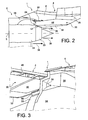
- each pipe 60 has an air ejection nozzle 64 ( figures 5 and 6 ) disposed near the front end of the rearward directed nozzle 33 and having the ejection axis 67 substantially parallel to the front end portion 53 of the thermal protection floor 32.
- Each ejection nozzle 64 thus allows the diffusion of a cooling air flow 65 in a manner substantially tangential to the floor 32.
- each pipe 60 passes through an annular seal of thermal or fire protection 63, which is for example a tongue seal of the type commonly called “finger seal” ( figures 5 and 6 ), and which substantially tightens the respective upstream ends of the nozzle 33 and the thermal protection floor 32.
- thermal or fire protection 63 which is for example a tongue seal of the type commonly called "finger seal” ( figures 5 and 6 ), and which substantially tightens the respective upstream ends of the nozzle 33 and the thermal protection floor 32.
- it can for example be provided respective passage spaces for the pipes 60, each of these spaces being provided between two consecutive tongues of the joint 63 ( figure 5 ).
- the nozzles 64 of the two pipes 60 are arranged substantially symmetrically with respect to the vertical plane of symmetry P of the propulsion unit.
- FIG 4 shows that the pipes 60 pass between the nozzle 33 and the lower edge of a substantially vertical wall 65 for separation between the cavity 62 delimited by the bifurcation walls 56 and the internal cavity 41 of the rear aerodynamic fairing 30.
- lateral flexible seals 66 are fixed on each of the side panels 44 of the rear aerodynamic fairing 30 by their upper end. so that their lower end comes into contact with the exhaust nozzle 33.
- lateral seals 66 make it possible, in a manner known per se, to limit the risk of hot air rising up from the primary flow into the space 55 between the front end portion 53 of the floor 32 and the nozzle 33.
- the lateral seals 66 furthermore make it possible to channel the flow of cooling air coming from the pipes 60 into the space 55 mentioned above and thus to optimize the cooling of the floor 32 and the nozzle 33.
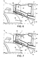
- the figure 7 illustrates a second preferred embodiment of the invention, which differs from the first embodiment described above in that the air intakes 58 are not formed in the bifurcation walls 56 but are formed in the side panels 44 the rear aerodynamic fairing 30, and the fact that the pipes 60 connected to these air intakes are housed within the interior cavity 41 of this fairing and open into the above-mentioned space 55 through orifices 68 of the protective floor thermal 32, along an air ejection axis 67 substantially orthogonal to the floor 32.
Landscapes
- Engineering & Computer Science (AREA)
- Chemical & Material Sciences (AREA)
- Combustion & Propulsion (AREA)
- Mechanical Engineering (AREA)
- Aviation & Aerospace Engineering (AREA)
- General Engineering & Computer Science (AREA)
- Structures Of Non-Positive Displacement Pumps (AREA)
- Turbine Rotor Nozzle Sealing (AREA)
Claims (8)
- Antriebseinheit (1) für ein Luftfahrzeug, die ein Zweistrom-Turbostrahltriebwerk (6) sowie einen Aufhängungsmast (4) aufweist, der zur Aufhängung dieses Turbostrahltriebwerks an der Tragfläche (2) oder am Rumpf eines Luftfahrzeugs bestimmt ist, wobei der Aufhängungsmast (4) eine hintere aerodynamische Verkleidung (30) enthält, die einen Wärmeschutzboden (32) aufweist, um den Aufhängungsmast (4) vor der Wärme eines Primärstroms (36) zu schützen, der von einem Abgasrohr (33) des Turbostrahltriebwerks kanalisiert wird, wobei die Antriebseinheit (1) Einrichtungen (58) zur Entnahme eines Kühlluftstroms aus einem Sekundärstrom (38) des Turbostrahltriebwerks sowie Luftzirkulationseinrichtungen (60) enthält, die von den Entnahmeeinrichtungen (58) gespeist werden und mindestens eine Ausgangsöffnung (64, 68) aufweisen, die in einen zwischen dem Wärmeschutzboden (32, 53) und dem Abgasrohr (33) liegenden Raum (55) mündet, wobei die Entnahmeeinrichtungen mindestens einen Lufteinlass (58) enthalten, der an die Luftzirkulationseinrichtungen (60) angeschlossen und in einer aerodynamischen Wand (44, 56) der Antriebseinheit (1) geformt ist, an die sich der Sekundärstrom (38) im Betrieb anpasst, und die sich in Längsrichtung gegenüber einer anderen gleichen aerodynamischen Wand (44, 56) der Antriebseinheit (1) erstreckt, mit der sie einen im Wesentlichen vom Sekundärstrom (38) isolierten Hohlraum (41, 62) begrenzt, dadurch gekennzeichnet, dass die aerodynamische Verkleidung sich in der Verlängerung einer Verzweigung erstreckt, die von zwei Verzweigungswänden (56) geformt wird, die zwei ringförmige Gondelhüllen (54) miteinander verbinden, die innen bzw. außen einen Ringraum (40) für die Strömung eines Sekundärstroms (38) im Turbostrahltriebwerk (6) begrenzen, und dass die aerodynamischen Wände die Verzweigungswände (56) oder Seitenwände (44) der hinteren aerodynamischen Verkleidung (30) sind.
- Antriebseinheit nach Anspruch 1, dadurch gekennzeichnet, dass die Luftzirkulationseinrichtungen mindestens ein Rohr (60) enthalten, das sich zumindest zum Teil im Hohlraum (41, 62) erstreckt.
- Antriebseinheit nach einem der Ansprüche 1 oder 2, dadurch gekennzeichnet, dass die Ausgangsöffnung (64) der Luftzirkulationseinrichtungen (60) eine Luftausstoßachse (67) aufweist, die im Wesentlichen parallel zu einem vorderen Endbereich (53) des Wärmeschutzbodens (32) ist.
- Antriebseinheit nach einem der Ansprüche 1 oder 2, dadurch gekennzeichnet, dass die Ausgangsöffnung (68) der Luftzirkulationseinrichtungen (60) den Wärmeschutzboden (32) durchquert.
- Antriebseinheit nach einem der vorhergehenden Ansprüche, dadurch gekennzeichnet, dass sie seitliche Dichtungen (66) aufweist, die den Raum (55) zwischen dem Wärmeschutzboden (32) und dem Abgasrohr (33) seitlich begrenzen.
- Luftfahrzeug, das mindestens eine Antriebseinheit (1) nach einem der vorhergehenden Ansprüche enthält.
- Verfahren zur Kühlung eines Wärmeschutzbodens (32) einer hinteren aerodynamischen Verkleidung (30) eines Aufhängungsmasts (4) einer Antriebseinheit (1) nach einem der Ansprüche 1 bis 5, wobei Kühlluft (65) im Sekundärstrom (38) des Turbostrahltriebwerks (6) dieser Antriebseinheit (1) durch die Entnahmeeinrichtungen (58) entnommen und in den zwischen dem Wärmeschutzboden (32) und dem Abgasrohr (33) des Turbostrahltriebwerks befindlichen Raum (55) durch die Luftzirkulationseinrichtungen (60) eingespeist wird.
- Verfahren nach Anspruch 7, dadurch gekennzeichnet, dass die Kühlluft (65) in den Raum (55) gemäß einer Richtung im Wesentlichen parallel zum Wärmeschutzboden (32) eingespeist wird, um einen Kühlluftfilm zwischen dem Wärmeschutzboden (32) und dem Primärstrom (36) des Turbostrahltriebwerks (6) zu formen.
Applications Claiming Priority (1)
| Application Number | Priority Date | Filing Date | Title |
|---|---|---|---|
| FR1156174A FR2977567B1 (fr) | 2011-07-07 | 2011-07-07 | Procede de refroidissement d'un plancher de protection thermique d'un carenage aerodynamique arriere d'un mat d'accrochage d'un ensemble propulsif d'aeronef |
Publications (3)
| Publication Number | Publication Date |
|---|---|
| EP2543864A2 EP2543864A2 (de) | 2013-01-09 |
| EP2543864A3 EP2543864A3 (de) | 2014-03-26 |
| EP2543864B1 true EP2543864B1 (de) | 2015-07-29 |
Family
ID=46317286
Family Applications (1)
| Application Number | Title | Priority Date | Filing Date |
|---|---|---|---|
| EP12173763.9A Active EP2543864B1 (de) | 2011-07-07 | 2012-06-27 | Antriebseinheit eines Luftfahrzeugs mit einem Hitzeschild einer hinteren Stromlinienverkleidung einer Triebwerksaufhängung sowie Kühlverfahren für das Hitzeschild |
Country Status (3)
| Country | Link |
|---|---|
| US (1) | US9435224B2 (de) |
| EP (1) | EP2543864B1 (de) |
| FR (1) | FR2977567B1 (de) |
Families Citing this family (16)
| Publication number | Priority date | Publication date | Assignee | Title |
|---|---|---|---|---|
| FR2988688B1 (fr) * | 2012-03-27 | 2014-05-09 | Airbus Operations Sas | Carenage aerodynamique arriere a tenue en temperature amelioree pour mat d'accrochage d'ensemble propulsif d'aeronef |
| FR3001197A1 (fr) * | 2013-01-22 | 2014-07-25 | Airbus Operations Sas | Ensemble propulsif d'un aeronef comprenant au moins un joint a brosse resistant aux hautes temperatures |
| FR3009339B1 (fr) * | 2013-07-30 | 2018-01-26 | Safran Aircraft Engines | Turbomachine comprenant un dispositif de refroidissement du pylone |
| US10427778B2 (en) | 2016-03-14 | 2019-10-01 | The Boeing Company | Heat shield assembly and method |
| US10759541B2 (en) * | 2016-10-14 | 2020-09-01 | Rohr, Inc. | Nacelle bifurcation with leading edge structure |
| FR3064605A1 (fr) * | 2017-03-28 | 2018-10-05 | Airbus Operations | Systeme de joints feu metalliques pour une attache moteur d'un aeronef |
| US10723470B2 (en) * | 2017-06-12 | 2020-07-28 | Raytheon Technologies Corporation | Aft fan counter-rotating turbine engine |
| US10627167B2 (en) | 2017-09-12 | 2020-04-21 | General Electric Company | Gas turbine engine having a heat absorption device utilizing phase change material |
| FR3072908B1 (fr) * | 2017-10-26 | 2021-02-26 | Safran Nacelles | Ensemble propulsif pour aeronef |
| CN112572811B (zh) * | 2019-09-30 | 2022-07-15 | 林瑶章 | 飞行载具及其推进装置 |
| EP3971401B1 (de) | 2020-05-05 | 2024-08-28 | Rohr, Inc. | Düse eines flugzeugantriebssystems mit internem strömungskanal |
| US11885240B2 (en) | 2021-05-24 | 2024-01-30 | General Electric Company Polska sp.z o.o | Gas turbine engine with fluid circuit and ejector |
| US11674396B2 (en) | 2021-07-30 | 2023-06-13 | General Electric Company | Cooling air delivery assembly |
| US11719115B2 (en) | 2021-11-05 | 2023-08-08 | General Electric Company | Clearance control structure for a gas turbine engine |
| US11788425B2 (en) | 2021-11-05 | 2023-10-17 | General Electric Company | Gas turbine engine with clearance control system |
| US11859500B2 (en) | 2021-11-05 | 2024-01-02 | General Electric Company | Gas turbine engine with a fluid conduit system and a method of operating the same |
Family Cites Families (16)
| Publication number | Priority date | Publication date | Assignee | Title |
|---|---|---|---|---|
| US5203163A (en) * | 1990-08-01 | 1993-04-20 | General Electric Company | Heat exchange arrangement in a gas turbine engine fan duct for cooling hot bleed air |
| FR2734320B1 (fr) * | 1995-05-15 | 1997-07-18 | Aerospatiale | Dispositif pour prelever et refroidir de l'air chaud au niveau d'un moteur d'aeronef |
| GB2302371A (en) * | 1995-06-21 | 1997-01-15 | Rolls Royce Plc | Gas turbine engine cooling air system |
| US6227800B1 (en) * | 1998-11-24 | 2001-05-08 | General Electric Company | Bay cooled turbine casing |
| FR2890696B1 (fr) * | 2005-09-12 | 2010-09-17 | Airbus France | Turbomoteur a bruit de jet attenue |
| FR2891248B1 (fr) * | 2005-09-28 | 2009-05-01 | Airbus France Sas | Ensemble moteur pour aeronef comprenant un moteur ainsi qu'un mat d'accrochage d'un tel moteur |
| FR2891250B1 (fr) * | 2005-09-28 | 2007-10-26 | Airbus France Sas | Ensemble moteur pour aeronef comprenant un moteur ainsi qu'un mat d'accrochage d'un tel moteur |
| GB0607773D0 (en) * | 2006-04-20 | 2006-05-31 | Rolls Royce Plc | A gas turbine engine |
| US8286415B2 (en) * | 2006-10-12 | 2012-10-16 | United Technologies Corporation | Turbofan engine having inner fixed structure including ducted passages |
| FR2921342B1 (fr) * | 2007-09-20 | 2010-03-12 | Airbus France | Carenage aerodynamique arriere inferieur pour dispositif d'accrochage d'un moteur d'aeronef |
| US8128100B2 (en) * | 2007-12-05 | 2012-03-06 | United Technologies Corporation | Laminate air seal for a gas turbine engine |
| FR2931134B1 (fr) | 2008-05-14 | 2010-06-18 | Airbus France | Mat d'accrochage de moteur d'aeronef comprenant un caisson de section en forme de cercle ou d'ellipse |
| FR2931133B1 (fr) | 2008-05-14 | 2010-06-18 | Airbus France | Mat d'accrochage de moteur comprenant des moyens de fixation des longerons et des panneaux agences en dehors de l'espace interieur de caisson |
| FR2960522B1 (fr) | 2010-05-27 | 2012-06-29 | Airbus Operations Sas | Procede de fabrication par formage superplastique et par eclissage d'une nervure pour carenage aerodynamique de mat d'accrochage de moteur d'aeronef |
| FR2960523B1 (fr) | 2010-05-27 | 2012-06-29 | Airbus Operations Sas | Procede de fabrication par formage superplastique et par eclissage d'une nervure pour carenage aerodynamique de mat d'accrochage de moteur d'aeronef |
| GB201011056D0 (en) * | 2010-07-01 | 2010-08-18 | Rolls Royce Plc | Pylon for attaching a gas turbine engine |
-
2011
- 2011-07-07 FR FR1156174A patent/FR2977567B1/fr not_active Expired - Fee Related
-
2012
- 2012-06-27 EP EP12173763.9A patent/EP2543864B1/de active Active
- 2012-07-06 US US13/542,880 patent/US9435224B2/en active Active
Also Published As
| Publication number | Publication date |
|---|---|
| FR2977567A1 (fr) | 2013-01-11 |
| US20130174572A1 (en) | 2013-07-11 |
| US9435224B2 (en) | 2016-09-06 |
| FR2977567B1 (fr) | 2014-12-26 |
| EP2543864A2 (de) | 2013-01-09 |
| EP2543864A3 (de) | 2014-03-26 |
Similar Documents
| Publication | Publication Date | Title |
|---|---|---|
| EP2543864B1 (de) | Antriebseinheit eines Luftfahrzeugs mit einem Hitzeschild einer hinteren Stromlinienverkleidung einer Triebwerksaufhängung sowie Kühlverfahren für das Hitzeschild | |
| CA2624005C (fr) | Ensemble moteur pour aeronef comprenant un moteur ainsi qu'un mat d'accrochage d'un tel moteur | |
| EP1928742B1 (de) | Motoranordnung für ein flugzeug mit einem motor sowie einer motormontagestruktur | |
| CA2699840C (fr) | Carenage aerodynamique arriere inferieur pour dispositif d'accrochage d'un moteur d'aeronef | |
| EP2146898B1 (de) | Hintere, untere aerodynamische verkleidung für die befestigungsvorrichtung eines flugzeugmotors | |
| EP2583900B1 (de) | Aerodynamische Heckverkleidung für eine Triebwerksaufhängung, welche ein Hitzeschild umfasst, das sich frei ausdehnen kann | |
| EP2152582B1 (de) | Antriebsanordnung für ein flugzeug mit gleitgondel | |
| EP2554478B1 (de) | Schwenkbare Verkleidung für Triebwerksvekleidungen getragen von diesen Triebwerksvekleidungen im geschlossenen Zustand | |
| FR2903666A1 (fr) | Ensemble moteur pour aeronef comprenant un capotage aerodynamique de jonction monte sur deux elements distincts | |
| EP2644505B1 (de) | Aerodynamische Heckverkleidung mit verbesserter Temperaturresistenz für Ausleger einer Antriebseinheit eines Luftfahrzeugs | |
| EP2038175A1 (de) | Triebwerksanordnung für ein flugzeug mit stützgestell für eine auf zwei separaten elementen montierte lüfterhaube | |
| EP2390186A2 (de) | Herstellungsverfahren für eine Rippe zur aerodynamischen Verkleidung eines Triebwerkspylons mittels superplastischer Formung und Verlaschung | |
| FR2948635A1 (fr) | Assemblage pour aeronef comprenant un mat d'accrochage de turbomachine dont les moyens d'attache sur la voilure sont agences en t | |
| FR3020798A1 (fr) | Ensemble propulsif pour aeronef comprenant un conduit formant barriere thermique integre au caisson de la structure rigide du mat d'accrochage | |
| FR2891255A1 (fr) | Ensemble moteur pour aeronef comprenant un moteur ainsi qu'un mat d'accrochage d'un tel moteur | |
| FR3000721A1 (fr) | Ensemble propulsif d'aeronef comprenant un carenage aerodynamique arriere de mat d'accrochage a parois laterales profilees pour l'injection d'air frais le long d'un plancher de protection thermique | |
| FR2960519A1 (fr) | Carenage aerodynamique de mat d'accrochage de moteur d'aeronef comprenant des raidisseurs ameliores | |
| FR3011584A1 (fr) | Extension de carter intermediaire | |
| FR2891249A1 (fr) | Mat d'accrochage de moteur pour aeronef | |
| FR2964947A1 (fr) | Carenage aerodynamique arriere pour mat d'accrochage de moteur d'aeronef |
Legal Events
| Date | Code | Title | Description |
|---|---|---|---|
| PUAI | Public reference made under article 153(3) epc to a published international application that has entered the european phase |
Free format text: ORIGINAL CODE: 0009012 |
|
| AK | Designated contracting states |
Kind code of ref document: A2 Designated state(s): AL AT BE BG CH CY CZ DE DK EE ES FI FR GB GR HR HU IE IS IT LI LT LU LV MC MK MT NL NO PL PT RO RS SE SI SK SM TR |
|
| AX | Request for extension of the european patent |
Extension state: BA ME |
|
| PUAL | Search report despatched |
Free format text: ORIGINAL CODE: 0009013 |
|
| AK | Designated contracting states |
Kind code of ref document: A3 Designated state(s): AL AT BE BG CH CY CZ DE DK EE ES FI FR GB GR HR HU IE IS IT LI LT LU LV MC MK MT NL NO PL PT RO RS SE SI SK SM TR |
|
| AX | Request for extension of the european patent |
Extension state: BA ME |
|
| RIC1 | Information provided on ipc code assigned before grant |
Ipc: F02K 1/34 20060101ALI20140220BHEP Ipc: F02K 1/82 20060101AFI20140220BHEP Ipc: F02C 7/20 20060101ALI20140220BHEP Ipc: F01D 25/14 20060101ALI20140220BHEP Ipc: B64C 7/02 20060101ALI20140220BHEP Ipc: B64D 29/00 20060101ALI20140220BHEP |
|
| 17P | Request for examination filed |
Effective date: 20140925 |
|
| RBV | Designated contracting states (corrected) |
Designated state(s): AL AT BE BG CH CY CZ DE DK EE ES FI FR GB GR HR HU IE IS IT LI LT LU LV MC MK MT NL NO PL PT RO RS SE SI SK SM TR |
|
| REG | Reference to a national code |
Ref country code: DE Ref legal event code: R079 Ref document number: 602012009077 Country of ref document: DE Free format text: PREVIOUS MAIN CLASS: F02K0001820000 Ipc: B64D0033040000 |
|
| GRAP | Despatch of communication of intention to grant a patent |
Free format text: ORIGINAL CODE: EPIDOSNIGR1 |
|
| INTG | Intention to grant announced |
Effective date: 20150213 |
|
| RIC1 | Information provided on ipc code assigned before grant |
Ipc: B64C 7/02 20060101ALI20150202BHEP Ipc: F02C 7/20 20060101ALI20150202BHEP Ipc: F01D 25/14 20060101ALI20150202BHEP Ipc: F02K 1/82 20060101ALI20150202BHEP Ipc: F02K 1/34 20060101ALI20150202BHEP Ipc: B64D 33/04 20060101AFI20150202BHEP Ipc: B64D 29/00 20060101ALI20150202BHEP |
|
| GRAS | Grant fee paid |
Free format text: ORIGINAL CODE: EPIDOSNIGR3 |
|
| GRAA | (expected) grant |
Free format text: ORIGINAL CODE: 0009210 |
|
| AK | Designated contracting states |
Kind code of ref document: B1 Designated state(s): AL AT BE BG CH CY CZ DE DK EE ES FI FR GB GR HR HU IE IS IT LI LT LU LV MC MK MT NL NO PL PT RO RS SE SI SK SM TR |
|
| REG | Reference to a national code |
Ref country code: GB Ref legal event code: FG4D Free format text: NOT ENGLISH |
|
| REG | Reference to a national code |
Ref country code: CH Ref legal event code: EP |
|
| REG | Reference to a national code |
Ref country code: AT Ref legal event code: REF Ref document number: 739048 Country of ref document: AT Kind code of ref document: T Effective date: 20150815 |
|
| REG | Reference to a national code |
Ref country code: IE Ref legal event code: FG4D Free format text: LANGUAGE OF EP DOCUMENT: FRENCH |
|
| REG | Reference to a national code |
Ref country code: DE Ref legal event code: R096 Ref document number: 602012009077 Country of ref document: DE |
|
| REG | Reference to a national code |
Ref country code: AT Ref legal event code: MK05 Ref document number: 739048 Country of ref document: AT Kind code of ref document: T Effective date: 20150729 |
|
| REG | Reference to a national code |
Ref country code: LT Ref legal event code: MG4D |
|
| REG | Reference to a national code |
Ref country code: NL Ref legal event code: MP Effective date: 20150729 |
|
| PG25 | Lapsed in a contracting state [announced via postgrant information from national office to epo] |
Ref country code: LT Free format text: LAPSE BECAUSE OF FAILURE TO SUBMIT A TRANSLATION OF THE DESCRIPTION OR TO PAY THE FEE WITHIN THE PRESCRIBED TIME-LIMIT Effective date: 20150729 Ref country code: GR Free format text: LAPSE BECAUSE OF FAILURE TO SUBMIT A TRANSLATION OF THE DESCRIPTION OR TO PAY THE FEE WITHIN THE PRESCRIBED TIME-LIMIT Effective date: 20151030 Ref country code: LV Free format text: LAPSE BECAUSE OF FAILURE TO SUBMIT A TRANSLATION OF THE DESCRIPTION OR TO PAY THE FEE WITHIN THE PRESCRIBED TIME-LIMIT Effective date: 20150729 Ref country code: NO Free format text: LAPSE BECAUSE OF FAILURE TO SUBMIT A TRANSLATION OF THE DESCRIPTION OR TO PAY THE FEE WITHIN THE PRESCRIBED TIME-LIMIT Effective date: 20151029 Ref country code: FI Free format text: LAPSE BECAUSE OF FAILURE TO SUBMIT A TRANSLATION OF THE DESCRIPTION OR TO PAY THE FEE WITHIN THE PRESCRIBED TIME-LIMIT Effective date: 20150729 |
|
| PG25 | Lapsed in a contracting state [announced via postgrant information from national office to epo] |
Ref country code: RS Free format text: LAPSE BECAUSE OF FAILURE TO SUBMIT A TRANSLATION OF THE DESCRIPTION OR TO PAY THE FEE WITHIN THE PRESCRIBED TIME-LIMIT Effective date: 20150729 Ref country code: HR Free format text: LAPSE BECAUSE OF FAILURE TO SUBMIT A TRANSLATION OF THE DESCRIPTION OR TO PAY THE FEE WITHIN THE PRESCRIBED TIME-LIMIT Effective date: 20150729 Ref country code: PT Free format text: LAPSE BECAUSE OF FAILURE TO SUBMIT A TRANSLATION OF THE DESCRIPTION OR TO PAY THE FEE WITHIN THE PRESCRIBED TIME-LIMIT Effective date: 20151130 Ref country code: AT Free format text: LAPSE BECAUSE OF FAILURE TO SUBMIT A TRANSLATION OF THE DESCRIPTION OR TO PAY THE FEE WITHIN THE PRESCRIBED TIME-LIMIT Effective date: 20150729 Ref country code: SE Free format text: LAPSE BECAUSE OF FAILURE TO SUBMIT A TRANSLATION OF THE DESCRIPTION OR TO PAY THE FEE WITHIN THE PRESCRIBED TIME-LIMIT Effective date: 20150729 Ref country code: IS Free format text: LAPSE BECAUSE OF FAILURE TO SUBMIT A TRANSLATION OF THE DESCRIPTION OR TO PAY THE FEE WITHIN THE PRESCRIBED TIME-LIMIT Effective date: 20151129 Ref country code: PL Free format text: LAPSE BECAUSE OF FAILURE TO SUBMIT A TRANSLATION OF THE DESCRIPTION OR TO PAY THE FEE WITHIN THE PRESCRIBED TIME-LIMIT Effective date: 20150729 Ref country code: ES Free format text: LAPSE BECAUSE OF FAILURE TO SUBMIT A TRANSLATION OF THE DESCRIPTION OR TO PAY THE FEE WITHIN THE PRESCRIBED TIME-LIMIT Effective date: 20150729 |
|
| PG25 | Lapsed in a contracting state [announced via postgrant information from national office to epo] |
Ref country code: NL Free format text: LAPSE BECAUSE OF FAILURE TO SUBMIT A TRANSLATION OF THE DESCRIPTION OR TO PAY THE FEE WITHIN THE PRESCRIBED TIME-LIMIT Effective date: 20150729 |
|
| PG25 | Lapsed in a contracting state [announced via postgrant information from national office to epo] |
Ref country code: IT Free format text: LAPSE BECAUSE OF FAILURE TO SUBMIT A TRANSLATION OF THE DESCRIPTION OR TO PAY THE FEE WITHIN THE PRESCRIBED TIME-LIMIT Effective date: 20150729 Ref country code: SK Free format text: LAPSE BECAUSE OF FAILURE TO SUBMIT A TRANSLATION OF THE DESCRIPTION OR TO PAY THE FEE WITHIN THE PRESCRIBED TIME-LIMIT Effective date: 20150729 Ref country code: DK Free format text: LAPSE BECAUSE OF FAILURE TO SUBMIT A TRANSLATION OF THE DESCRIPTION OR TO PAY THE FEE WITHIN THE PRESCRIBED TIME-LIMIT Effective date: 20150729 Ref country code: CZ Free format text: LAPSE BECAUSE OF FAILURE TO SUBMIT A TRANSLATION OF THE DESCRIPTION OR TO PAY THE FEE WITHIN THE PRESCRIBED TIME-LIMIT Effective date: 20150729 Ref country code: EE Free format text: LAPSE BECAUSE OF FAILURE TO SUBMIT A TRANSLATION OF THE DESCRIPTION OR TO PAY THE FEE WITHIN THE PRESCRIBED TIME-LIMIT Effective date: 20150729 |
|
| REG | Reference to a national code |
Ref country code: DE Ref legal event code: R097 Ref document number: 602012009077 Country of ref document: DE |
|
| PG25 | Lapsed in a contracting state [announced via postgrant information from national office to epo] |
Ref country code: RO Free format text: LAPSE BECAUSE OF FAILURE TO SUBMIT A TRANSLATION OF THE DESCRIPTION OR TO PAY THE FEE WITHIN THE PRESCRIBED TIME-LIMIT Effective date: 20150729 |
|
| PLBE | No opposition filed within time limit |
Free format text: ORIGINAL CODE: 0009261 |
|
| STAA | Information on the status of an ep patent application or granted ep patent |
Free format text: STATUS: NO OPPOSITION FILED WITHIN TIME LIMIT |
|
| REG | Reference to a national code |
Ref country code: FR Ref legal event code: PLFP Year of fee payment: 5 |
|
| 26N | No opposition filed |
Effective date: 20160502 |
|
| PG25 | Lapsed in a contracting state [announced via postgrant information from national office to epo] |
Ref country code: SI Free format text: LAPSE BECAUSE OF FAILURE TO SUBMIT A TRANSLATION OF THE DESCRIPTION OR TO PAY THE FEE WITHIN THE PRESCRIBED TIME-LIMIT Effective date: 20150729 |
|
| PG25 | Lapsed in a contracting state [announced via postgrant information from national office to epo] |
Ref country code: BE Free format text: LAPSE BECAUSE OF NON-PAYMENT OF DUE FEES Effective date: 20160630 |
|
| REG | Reference to a national code |
Ref country code: DE Ref legal event code: R119 Ref document number: 602012009077 Country of ref document: DE |
|
| PG25 | Lapsed in a contracting state [announced via postgrant information from national office to epo] |
Ref country code: MC Free format text: LAPSE BECAUSE OF FAILURE TO SUBMIT A TRANSLATION OF THE DESCRIPTION OR TO PAY THE FEE WITHIN THE PRESCRIBED TIME-LIMIT Effective date: 20150729 |
|
| REG | Reference to a national code |
Ref country code: CH Ref legal event code: PL |
|
| REG | Reference to a national code |
Ref country code: IE Ref legal event code: MM4A |
|
| PG25 | Lapsed in a contracting state [announced via postgrant information from national office to epo] |
Ref country code: DE Free format text: LAPSE BECAUSE OF NON-PAYMENT OF DUE FEES Effective date: 20170103 Ref country code: CH Free format text: LAPSE BECAUSE OF NON-PAYMENT OF DUE FEES Effective date: 20160630 Ref country code: LI Free format text: LAPSE BECAUSE OF NON-PAYMENT OF DUE FEES Effective date: 20160630 |
|
| PG25 | Lapsed in a contracting state [announced via postgrant information from national office to epo] |
Ref country code: IE Free format text: LAPSE BECAUSE OF NON-PAYMENT OF DUE FEES Effective date: 20160627 |
|
| REG | Reference to a national code |
Ref country code: FR Ref legal event code: PLFP Year of fee payment: 6 |
|
| PG25 | Lapsed in a contracting state [announced via postgrant information from national office to epo] |
Ref country code: HU Free format text: LAPSE BECAUSE OF FAILURE TO SUBMIT A TRANSLATION OF THE DESCRIPTION OR TO PAY THE FEE WITHIN THE PRESCRIBED TIME-LIMIT; INVALID AB INITIO Effective date: 20120627 Ref country code: CY Free format text: LAPSE BECAUSE OF FAILURE TO SUBMIT A TRANSLATION OF THE DESCRIPTION OR TO PAY THE FEE WITHIN THE PRESCRIBED TIME-LIMIT Effective date: 20150729 Ref country code: SM Free format text: LAPSE BECAUSE OF FAILURE TO SUBMIT A TRANSLATION OF THE DESCRIPTION OR TO PAY THE FEE WITHIN THE PRESCRIBED TIME-LIMIT Effective date: 20150729 |
|
| REG | Reference to a national code |
Ref country code: FR Ref legal event code: PLFP Year of fee payment: 7 |
|
| PG25 | Lapsed in a contracting state [announced via postgrant information from national office to epo] |
Ref country code: MT Free format text: LAPSE BECAUSE OF FAILURE TO SUBMIT A TRANSLATION OF THE DESCRIPTION OR TO PAY THE FEE WITHIN THE PRESCRIBED TIME-LIMIT Effective date: 20150729 Ref country code: LU Free format text: LAPSE BECAUSE OF NON-PAYMENT OF DUE FEES Effective date: 20160627 Ref country code: TR Free format text: LAPSE BECAUSE OF FAILURE TO SUBMIT A TRANSLATION OF THE DESCRIPTION OR TO PAY THE FEE WITHIN THE PRESCRIBED TIME-LIMIT Effective date: 20150729 Ref country code: MK Free format text: LAPSE BECAUSE OF FAILURE TO SUBMIT A TRANSLATION OF THE DESCRIPTION OR TO PAY THE FEE WITHIN THE PRESCRIBED TIME-LIMIT Effective date: 20150729 |
|
| PG25 | Lapsed in a contracting state [announced via postgrant information from national office to epo] |
Ref country code: BG Free format text: LAPSE BECAUSE OF FAILURE TO SUBMIT A TRANSLATION OF THE DESCRIPTION OR TO PAY THE FEE WITHIN THE PRESCRIBED TIME-LIMIT Effective date: 20150729 |
|
| PG25 | Lapsed in a contracting state [announced via postgrant information from national office to epo] |
Ref country code: AL Free format text: LAPSE BECAUSE OF FAILURE TO SUBMIT A TRANSLATION OF THE DESCRIPTION OR TO PAY THE FEE WITHIN THE PRESCRIBED TIME-LIMIT Effective date: 20150729 |
|
| PGFP | Annual fee paid to national office [announced via postgrant information from national office to epo] |
Ref country code: GB Payment date: 20240620 Year of fee payment: 13 |
|
| PGFP | Annual fee paid to national office [announced via postgrant information from national office to epo] |
Ref country code: FR Payment date: 20240628 Year of fee payment: 13 |