EP2543864B1 - Aircraft propulsion assembly with a heat shield for thermal protection of a rear aerodynamic fairing of a pylon and a cooling method for the heat shield - Google Patents
Aircraft propulsion assembly with a heat shield for thermal protection of a rear aerodynamic fairing of a pylon and a cooling method for the heat shield Download PDFInfo
- Publication number
- EP2543864B1 EP2543864B1 EP12173763.9A EP12173763A EP2543864B1 EP 2543864 B1 EP2543864 B1 EP 2543864B1 EP 12173763 A EP12173763 A EP 12173763A EP 2543864 B1 EP2543864 B1 EP 2543864B1
- Authority
- EP
- European Patent Office
- Prior art keywords
- thermal protection
- propulsion system
- turbojet
- protection floor
- air
- Prior art date
- Legal status (The legal status is an assumption and is not a legal conclusion. Google has not performed a legal analysis and makes no representation as to the accuracy of the status listed.)
- Active
Links
Images


Classifications
-
- F—MECHANICAL ENGINEERING; LIGHTING; HEATING; WEAPONS; BLASTING
- F01—MACHINES OR ENGINES IN GENERAL; ENGINE PLANTS IN GENERAL; STEAM ENGINES
- F01D—NON-POSITIVE DISPLACEMENT MACHINES OR ENGINES, e.g. STEAM TURBINES
- F01D25/00—Component parts, details, or accessories, not provided for in, or of interest apart from, other groups
- F01D25/08—Cooling; Heating; Heat-insulation
- F01D25/14—Casings modified therefor
-
- B—PERFORMING OPERATIONS; TRANSPORTING
- B64—AIRCRAFT; AVIATION; COSMONAUTICS
- B64C—AEROPLANES; HELICOPTERS
- B64C7/00—Structures or fairings not otherwise provided for
- B64C7/02—Nacelles
-
- B—PERFORMING OPERATIONS; TRANSPORTING
- B64—AIRCRAFT; AVIATION; COSMONAUTICS
- B64D—EQUIPMENT FOR FITTING IN OR TO AIRCRAFT; FLIGHT SUITS; PARACHUTES; ARRANGEMENTS OR MOUNTING OF POWER PLANTS OR PROPULSION TRANSMISSIONS IN AIRCRAFT
- B64D29/00—Power-plant nacelles, fairings, or cowlings
-
- B—PERFORMING OPERATIONS; TRANSPORTING
- B64—AIRCRAFT; AVIATION; COSMONAUTICS
- B64D—EQUIPMENT FOR FITTING IN OR TO AIRCRAFT; FLIGHT SUITS; PARACHUTES; ARRANGEMENTS OR MOUNTING OF POWER PLANTS OR PROPULSION TRANSMISSIONS IN AIRCRAFT
- B64D33/00—Arrangements in aircraft of power plant parts or auxiliaries not otherwise provided for
- B64D33/04—Arrangements in aircraft of power plant parts or auxiliaries not otherwise provided for of exhaust outlets or jet pipes
- B64D33/06—Silencing exhaust or propulsion jets
-
- F—MECHANICAL ENGINEERING; LIGHTING; HEATING; WEAPONS; BLASTING
- F02—COMBUSTION ENGINES; HOT-GAS OR COMBUSTION-PRODUCT ENGINE PLANTS
- F02C—GAS-TURBINE PLANTS; AIR INTAKES FOR JET-PROPULSION PLANTS; CONTROLLING FUEL SUPPLY IN AIR-BREATHING JET-PROPULSION PLANTS
- F02C7/00—Features, components parts, details or accessories, not provided for in, or of interest apart form groups F02C1/00 - F02C6/00; Air intakes for jet-propulsion plants
- F02C7/20—Mounting or supporting of plant; Accommodating heat expansion or creep
-
- F—MECHANICAL ENGINEERING; LIGHTING; HEATING; WEAPONS; BLASTING
- F02—COMBUSTION ENGINES; HOT-GAS OR COMBUSTION-PRODUCT ENGINE PLANTS
- F02K—JET-PROPULSION PLANTS
- F02K1/00—Plants characterised by the form or arrangement of the jet pipe or nozzle; Jet pipes or nozzles peculiar thereto
- F02K1/78—Other construction of jet pipes
- F02K1/82—Jet pipe walls, e.g. liners
- F02K1/822—Heat insulating structures or liners, cooling arrangements, e.g. post combustion liners; Infra-red radiation suppressors
-
- F—MECHANICAL ENGINEERING; LIGHTING; HEATING; WEAPONS; BLASTING
- F05—INDEXING SCHEMES RELATING TO ENGINES OR PUMPS IN VARIOUS SUBCLASSES OF CLASSES F01-F04
- F05D—INDEXING SCHEME FOR ASPECTS RELATING TO NON-POSITIVE-DISPLACEMENT MACHINES OR ENGINES, GAS-TURBINES OR JET-PROPULSION PLANTS
- F05D2260/00—Function
- F05D2260/20—Heat transfer, e.g. cooling
-
- Y—GENERAL TAGGING OF NEW TECHNOLOGICAL DEVELOPMENTS; GENERAL TAGGING OF CROSS-SECTIONAL TECHNOLOGIES SPANNING OVER SEVERAL SECTIONS OF THE IPC; TECHNICAL SUBJECTS COVERED BY FORMER USPC CROSS-REFERENCE ART COLLECTIONS [XRACs] AND DIGESTS
- Y02—TECHNOLOGIES OR APPLICATIONS FOR MITIGATION OR ADAPTATION AGAINST CLIMATE CHANGE
- Y02T—CLIMATE CHANGE MITIGATION TECHNOLOGIES RELATED TO TRANSPORTATION
- Y02T50/00—Aeronautics or air transport
- Y02T50/60—Efficient propulsion technologies, e.g. for aircraft
Definitions
- the present invention relates to the field of aircraft engine attachment masts and more specifically relates to the thermal protection of a double-jet turbojet coupling pylon.
- an attachment mast also called “EMS” ( Engine Mounting Structure )
- EMS Engine Mounting Structure
- Such an attachment pylon is in fact provided to form the connecting interface between a motor and a wing of the aircraft. It transmits to the structure of this aircraft the forces generated by its associated engine, and also allows the flow of fuel, electrical, hydraulic, and air between the engine and the aircraft.
- the attachment mast has a rigid structure also called primary structure, usually of the "box” type, that is to say formed by the assembly of upper and lower spars and side panels connected together through transverse stiffening ribs.
- the device is provided with attachment means interposed between the engine and the rigid structure, these means generally comprising two engine attachments, and a device for taking up the thrust forces generated by the engine.
- this recovery device usually comprises two lateral rods connected on the one hand to a rear part of the fan housing of the engine, and on the other hand to a rear attachment fixed to the central casing of the latter.
- the attachment mast also comprises another series of fasteners constituting a mounting system interposed between the rigid structure and the wing of the aircraft, this system usually consisting of two or three fasteners.
- the mast is provided with a plurality of secondary structures segregating and maintaining the systems while supporting aerodynamic fairing elements, the latter generally taking the form of panel assemblies reported on the structures.
- the secondary structures are different from the rigid structure in that they are not intended to ensure the transfer of forces from the engine and to be transmitted to the wing of the aircraft.
- Secondary structures include the rear aerodynamic fairing, also known as " APF " (of the English “Aft Pylon Fairing” ), which provides a plurality of functions among which is noted the formation of a thermal or fire barrier, and the formation of aerodynamic continuity between the output of the engine and the rigging mast.
- the fairing adopts a lower position when the engine is intended to be placed under the wing, and adopts a higher position when the engine is intended to be placed above the wing.
- EP 0 743 435 A1 is considered the closest state of the art.
- An example of known fairing of the prior art is disclosed in the document EP 2,190,739 .
- This rear aerodynamic fairing generally takes the form of a box comprising two side panels assembled together by transverse stiffening internal ribs spaced from each other in a longitudinal direction of the fairing, and a thermal protection floor.
- the side panels of the rear aerodynamic fairing are designed to be matched externally by a secondary flow of the engine, because of their location in the annular channel of secondary flow of the engine and / or at the outlet of this channel.
- the thermal protection floor has an external surface designed to be fitted with a primary flow of the engine, consisting of exhaust gases that can reach temperatures of the order of 540 ° C, these temperatures tending to increase with recent developments in the techniques. implemented in turbojet engines.
- a front end portion of the thermal protection floor is usually arranged at right and relatively short distance from the outer face of an exhaust nozzle of the turbojet engine, the inner face of which is matched by the relatively hot primary flow while the outer face is bathed by the relatively cold secondary flow of the turbojet engine.
- this nozzle which is located opposite the aforesaid front end portion of the thermal protection floor is not bathed or is little bathed by the secondary flow and therefore has a considerably higher temperature than the rest of the nozzle.
- This hottest region of the nozzle also tends to radially heat the front end portion of the thermal protection floor, so that the latter can reach considerably higher temperatures than the rest of this floor.
- the invention aims in particular to provide a simple, economical and effective solution to these problems, to avoid at least partly the aforementioned drawbacks.
- an aircraft propulsion unit as defined in claim 1, comprising a turbofan engine and an attachment pylon for attaching the turbojet to the wing or the fuselage of an aircraft, said attachment pylon comprising a rear aerodynamic fairing comprising a thermal protection floor to protect said pylon from the heat of a primary stream coming from an exhaust nozzle of said turbojet engine.
- the propulsion unit comprises means for sampling a flow of cooling air in a secondary flow of the turbojet engine as well as air circulation means fed by said sampling means and having at least one orifice outlet opening into a space between the thermal protection floor and the exhaust nozzle.
- the invention thus makes it possible to inject a part of the secondary flow, forming said flow of cooling air, in the relatively thin space between the thermal protection floor and the exhaust nozzle.
- the invention thus allows a homogenization of the temperature within these two elements, and therefore a considerable increase in their life.
- said sampling means comprise at least one air intake connected to said air circulation means and formed in an aerodynamic wall of the propulsion unit, wall which is matched by the secondary flow in operation.
- the air intake is advantageously an aerodynamic grip, particularly of the type well known by the acronym NACA.
- the aerodynamic wall in question here may be any wall bathed by the secondary flow, such as for example an inner or outer shell nacelle, and this wall is preferably a wall extending longitudinally opposite a another similar aerodynamic wall of said propulsion unit, with which it delimits a substantially isolated cavity of said secondary flow.
- said aerodynamic walls are mutually interconnecting bifurcation walls.
- two annular nacelle envelopes which delimit, respectively internally and externally, an annular space of flow of said secondary flow in said turbojet engine.
- the aforementioned aerodynamic walls form a bifurcation within the flow space of the secondary flow, and the cavity defined between these two walls allows, in a manner known per se, the passage of a front portion of the a rigid structure of the attachment pylon which carries means for attaching the turbojet engine.
- said aerodynamic walls may be side walls of the rear aerodynamic fairing.
- the cavity defined between these walls constitutes the interior space of this fairing.
- said sampling means advantageously comprise two air intakes respectively formed in the two aforementioned longitudinal aerodynamic walls extending facing one another.
- said air circulation means preferably comprise at least one pipe extending at least partly in the aforementioned cavity.
- Such a pipe allows efficient channeling of the cooling air flow.
- the aforementioned outlet orifice of said air circulation means preferably opens at a front end of said space between the thermal protection floor and the exhaust nozzle.
- the outlet orifice of said air circulation means advantageously has an air ejection axis substantially parallel to a front end portion of the thermal protection floor.
- the cooling air can be injected into this space in a rearward direction substantially tangential to the thermal protection floor, and thus bathing at best the respective parts of the thermal protection floor and the exhaust nozzle which delimit said space.
- this flow can form a relatively cool air film along the thermal protection floor, beyond the rear end of the exhaust nozzle , and thus interposed between a portion of this floor and the primary flow so as to protect this part of the floor of the heat of this primary flow.
- the outlet of said air circulation means can pass through the thermal protection floor.
- the cooling air can be injected into said space by passing through the thermal protection floor and spreading along exhaust nozzle in said space in a substantially centrifugal manner from said outlet port.
- the propulsion unit according to the invention preferably comprises lateral sealing joints which laterally delimit said space between the thermal protection floor and the exhaust nozzle.
- these seals are of additional interest in that they can channel the cooling air diffused by said air circulation means within the aforementioned space and thus improve the air flow. cooling efficiency of the respective parts of the thermal protection floor and the exhaust nozzle which define this space.
- the invention also relates to an aircraft comprising at least one propulsion unit of the type described above.
- the invention further relates to a method of cooling a thermal protection floor of a rear aerodynamic fairing of a propulsion mast of the type described above as defined in claim 7, wherein the cooling air is taken from the secondary flow of the turbojet engine of this propulsion unit by said sampling means and is injected into said space between the floor of thermal protection and the exhaust nozzle of the turbojet engine by said air circulation means.
- the cooling air is preferably injected into said space in a direction substantially parallel to said thermal protection floor so as to form a cooling air film between said thermal protection floor and said primary flow of the turbojet.
- this propulsion unit 1 for an aircraft according to a first preferred embodiment of the present invention, intended to be fixed under a wing 2 of this aircraft, this propulsion unit 1 comprising an attachment pylon 4, and a turbojet engine double flow 6 hooked under the attachment pole 4.
- the attachment pylon 4 comprises a rigid structure 8, also called a primary structure, carrying means for fastening the engine 6, these attachment means having a plurality of engine attachments 10, 12, as well as a device 14 for taking up the thrust forces generated by the turbojet engine 6.
- the attachment mast 4 comprises another series of fasteners (not shown) attached to the rigid structure 8 and to ensure the suspension of this propulsion unit 1 under the wing 2 of the aircraft.
- the propulsion unit 1 is intended to be surrounded by a nacelle (not shown).
- X is the longitudinal direction of the device 4 which is also comparable to the longitudinal direction of the turbojet engine 6 and that of the lower rear aerodynamic fairing which will be presented hereinafter, this direction X being parallel to a longitudinal axis 5 of this turbojet engine.
- the direction transversely oriented with respect to the device 4 is also referred to as Y and can also be assimilated to the direction transverse of the turbojet engine 6 and that of the lower rear aerodynamic fairing, and Z the vertical direction or the height, these three directions X, Y and Z being orthogonal to each other.
- front and rear are to be considered with respect to a direction of advancement of the aircraft during operation of the turbojet engine 6, this direction being represented schematically by the arrow 7.
- turbojet engine 6 has at the front of a large fan casing 18 delimiting an annular fan duct 20, and comprises a rearward central casing 22 of smaller size, enclosing the core of this fan. turbojet. Housings 18 and 22 are of course integral with each other.
- the engine fasteners 10, 12 of the device 4 are provided in the number of two, respectively called front engine attachment and rear engine attachment.
- the rigid structure 8 takes the form of a box extending from the rear towards the front, substantially in the X direction, provided with transverse ribs (not shown) each taking the form of a rectangle oriented in a YZ plane .
- the attachment means comprise firstly the front engine attachment 10 interposed between a front end of the rigid structure 8 also called pyramid, and an upper part of the fan casing 18.
- the forward engine attachment 10 is designed so conventional and known to those skilled in the art.
- the rear engine attachment 12 also made in a conventional manner and known to those skilled in the art, is interposed between the rigid structure 8 and the central casing 22.
- the secondary structures of the mast 4 include a forward aerodynamic structure 24, a rear aerodynamic structure 26, a connecting fairing 28 of the forward and aft aerodynamic structures, and a lower rear aerodynamic fairing 30.
- the aerodynamic structure before 24 is placed in the extension lower front of the wing 2 and above the primary structure 8. It is fixedly mounted on the rigid structure 8, and has an aerodynamic profile function between an upper part of fan cowls articulated on this aerodynamic structure before 24, and the leading edge of the wing.
- This aerodynamic structure before 24 then not only has an aerodynamic fairing function, but it also allows the introduction, segregation and routing of different systems (air, electrical, hydraulic, fuel).
- the front part of this structure 24 is not in contact with the rigid structure 8, it is usually interposed a heat exchanger in the space defined between these two elements.
- the connecting fairing 28 Directly in the rear extension of this structure 24, still under the wing and mounted above the rigid structure 8, is the connecting fairing 28, also called “karman”. Then, still towards the rear, the connecting fairing 28 is extended by the rear aerodynamic structure 26, called RSS (of the English “Rear Secondary Structure "), which contains a part of the equipment of the mast. This structure 26 is preferably located entirely rearward with respect to the rigid structure 8, and is therefore attached under the wing of the aircraft.
- the lower rear aerodynamic fairing 30 also called “shield” or "Aft Pylon Fairing ". His essential functions are the formation of a thermal barrier, also called fireproof, used to protect the mast and the wing from the heat released by the primary flow, and the formation of an aerodynamic continuity between the engine output and the mast of the engine. hanging.
- the lower rear aerodynamic fairing 30 has a thermal protection floor 32 provided with an outer surface designed to be wedged by a primary flow of the motor which it delimits partially radially outwardly. , this primary flow, shown schematically by the arrow 36, escaping from a nozzle 33 of the engine.
- the shroud 30 also comprises two lateral panels 44 which are in turn provided to be fitted externally with a secondary flow of the motor shown schematically by the arrow 38, due to their implantation in the annular channel 40 of the secondary flow of the engine. ( figure 1 ) and / or at the output thereof.
- the fairing 30 is thus in the form of a box having an internal cavity 41 ( figure 4 ).
- the floor 32 for thermal protection of the mast and the wing with respect to the flow primary 36 constitutes a lower portion of the shroud 30, while a closure spar 51, opposite the floor 32, constitutes an upper portion of this fairing 30 ( figure 1 ).
- the fairing 30 would become an upper rear aerodynamic fairing.
- a front end portion 53 of the floor 32 extends opposite, at a short distance, from an upper end of the nozzle 33 ( figure 4 ).
- the clearance between this floor 32 and the nozzle 33 defines a space 55 between these two elements and is particularly designed to take into account the deformations of the turbojet inherent in the different phases of operation of the latter.
- the lower rear aerodynamic fairing 30 in the general box shape is mounted on the rear aerodynamic structure 26 and the rigid structure 8 ( figure 1 ).
- the shroud 30 preferably has a plane of symmetry P corresponding to a plane XZ, this plane P also constituting a vertical plane of symmetry for the whole of the attachment pylon 4, and for the engine 6.
- the two side panels 44 of the shroud 30 are roughly oriented in a plane XZ and arranged on either side of the plane P. They are assembled together by transverse stiffening ribs 46 spaced apart from each other in the direction X, each of these ribs 46 being oriented in a plane YZ and taking for example the shape of a rectangle or a square.
- the side panels 44 are fixedly mounted and directly on the lateral portions of each of the inner ribs 46, using conventional means known to those skilled in the art.
- the fairing 30 integrates the thermal protection floor 32 in the lower part of the box, the upper part being closed by the closing spar 51 opposite the floor 32.
- the upper part of the box may be devoid of spar closing, and only closed by the elements 8, 26 directly adjacent in the direction Z.
- the fairing 30 is broken down into two distinct but integral portions of each other, namely a front portion 50 constituting the major part of the fairing, for example 60 to 85% of it in terms of length in the direction X, and a smaller rear portion 52 generally taking the form of a pyramid or tip whose base is rigidly connected to the front portion 50, and whose apex forms a rear end of the shroud 30.
- the front portion 50 has a substantially homogeneous cross section over its entire length.
- the side panels 44 and the closure spar 51 preferably each extend in one piece from one end to the other of the fairing 30, i.e. both along the front portion 50 , and the along the rear portion 52.
- the thermal protection floor 32 preferably extends in one piece only on the front portion 50, and not on the rear portion 52, although it could of course be envisaged , without departing from the scope of the invention. This particularity is explained in particular by the fact that the rear portion 52 in the form of a pyramid progressively moves away from the axis of the motor, so that the primary flow, which in any case loses heat intensity going towards the rear, induces a lower thermal impact on the lower closure element of the pyramid 52.
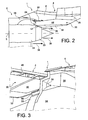
- the figure 2 represents a rear part of the propulsion unit 1, including an inner part of the nacelle of this set 1, this inner part comprising an inner annular envelope 54, sometimes called IFS (of the English “Inner Fan Structure” ), intended to internally delimit the channel 40 of secondary flow, and two longitudinal walls 56, only one of which is visible on the figure 2 , which are connected to the inner casing 54 and intended to guide the secondary flow 38 around certain parts of the pylon 4 which pass through the channel 40 of secondary flow, such as a front portion of the rigid structure 8 as well as the engine fasteners 10 and 12.
- the longitudinal walls 56 of the nacelle delimit a cavity 62 (FIG. figure 4 ) which is substantially isolated from the secondary flow in which these elements of the attachment pylon 4 extend, and which is commonly called “bifurcation”.
- each longitudinal wall 56 will thus be called “bifurcation wall”.
- each bifurcation wall 56 comprises an air intake 58 ( Figures 2 to 5 ) for taking a part of the secondary flow of the turbojet engine to form a cooling air flow 59 ( figure 5 ).
- the air intake 58 ( figure 3 ) is preferably an aerodynamic air intake having a NACA-type configuration, but it may alternatively be of any other type, and optionally have scoop means projecting into the secondary flow.
- Each air intake 58 is sealingly connected to a corresponding air circulation pipe 60 ( figure 4 ) arranged inside the cavity 62 delimited by the bifurcation walls 56, and opening into the aforesaid space 55, close to the front end of the exhaust nozzle 33.
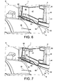
- each pipe 60 has an air ejection nozzle 64 ( figures 5 and 6 ) disposed near the front end of the rearward directed nozzle 33 and having the ejection axis 67 substantially parallel to the front end portion 53 of the thermal protection floor 32.
- Each ejection nozzle 64 thus allows the diffusion of a cooling air flow 65 in a manner substantially tangential to the floor 32.
- each pipe 60 passes through an annular seal of thermal or fire protection 63, which is for example a tongue seal of the type commonly called “finger seal” ( figures 5 and 6 ), and which substantially tightens the respective upstream ends of the nozzle 33 and the thermal protection floor 32.
- thermal or fire protection 63 which is for example a tongue seal of the type commonly called "finger seal” ( figures 5 and 6 ), and which substantially tightens the respective upstream ends of the nozzle 33 and the thermal protection floor 32.
- it can for example be provided respective passage spaces for the pipes 60, each of these spaces being provided between two consecutive tongues of the joint 63 ( figure 5 ).
- the nozzles 64 of the two pipes 60 are arranged substantially symmetrically with respect to the vertical plane of symmetry P of the propulsion unit.
- FIG 4 shows that the pipes 60 pass between the nozzle 33 and the lower edge of a substantially vertical wall 65 for separation between the cavity 62 delimited by the bifurcation walls 56 and the internal cavity 41 of the rear aerodynamic fairing 30.
- lateral flexible seals 66 are fixed on each of the side panels 44 of the rear aerodynamic fairing 30 by their upper end. so that their lower end comes into contact with the exhaust nozzle 33.
- lateral seals 66 make it possible, in a manner known per se, to limit the risk of hot air rising up from the primary flow into the space 55 between the front end portion 53 of the floor 32 and the nozzle 33.
- the lateral seals 66 furthermore make it possible to channel the flow of cooling air coming from the pipes 60 into the space 55 mentioned above and thus to optimize the cooling of the floor 32 and the nozzle 33.
- the figure 7 illustrates a second preferred embodiment of the invention, which differs from the first embodiment described above in that the air intakes 58 are not formed in the bifurcation walls 56 but are formed in the side panels 44 the rear aerodynamic fairing 30, and the fact that the pipes 60 connected to these air intakes are housed within the interior cavity 41 of this fairing and open into the above-mentioned space 55 through orifices 68 of the protective floor thermal 32, along an air ejection axis 67 substantially orthogonal to the floor 32.
Description
La présente invention se rapporte au domaine des mâts d'accrochage de moteur d'aéronef et concerne plus précisément la protection thermique d'un mât d'accrochage de turboréacteur à double flux.The present invention relates to the field of aircraft engine attachment masts and more specifically relates to the thermal protection of a double-jet turbojet coupling pylon.
D'une manière générale, un mât d'accrochage, également dénommé « EMS » (de l'anglais « Engine Mounting Structure »), permet de suspendre un moteur au-dessous de la voilure d'un aéronef, de monter ce moteur au-dessus de cette même voilure, ou encore de rapporter ce moteur en partie arrière du fuselage de l'aéronef.In general, an attachment mast, also called "EMS" ( Engine Mounting Structure ), allows to suspend an engine below the wing of an aircraft, to mount this engine to above this same wing, or to bring this engine back part of the fuselage of the aircraft.
Un tel mât d'accrochage est en effet prévu pour constituer l'interface de liaison entre un moteur et une voilure de l'aéronef. Il permet de transmettre à la structure de cet aéronef les efforts générés par son moteur associé, et autorise également le cheminement du carburant, des systèmes électriques, hydrauliques, et air entre le moteur et l'aéronef.Such an attachment pylon is in fact provided to form the connecting interface between a motor and a wing of the aircraft. It transmits to the structure of this aircraft the forces generated by its associated engine, and also allows the flow of fuel, electrical, hydraulic, and air between the engine and the aircraft.
Afin d'assurer la transmission des efforts, le mât d'accrochage comporte une structure rigide également dénommée structure primaire, habituellement du type « caisson », c'est-à-dire formée par l'assemblage de longerons supérieurs et inférieurs et de panneaux latéraux raccordés entre eux par l'intermédiaire de nervures transversales de rigidification.In order to ensure the transmission of forces, the attachment mast has a rigid structure also called primary structure, usually of the "box" type, that is to say formed by the assembly of upper and lower spars and side panels connected together through transverse stiffening ribs.
D'autre part, le dispositif est muni de moyens d'accrochage interposés entre le moteur et la structure rigide, ces moyens comportant d'une manière générale deux attaches moteur, ainsi qu'un dispositif de reprise des efforts de poussée générés par le moteur. Dans l'art antérieur, ce dispositif de reprise comprend habituellement deux bielles latérales raccordées d'une part à une partie arrière du carter de soufflante du moteur, et d'autre part à une attache arrière fixée sur le carter central de ce dernier.On the other hand, the device is provided with attachment means interposed between the engine and the rigid structure, these means generally comprising two engine attachments, and a device for taking up the thrust forces generated by the engine. . In the prior art, this recovery device usually comprises two lateral rods connected on the one hand to a rear part of the fan housing of the engine, and on the other hand to a rear attachment fixed to the central casing of the latter.
De la même façon, le mât d'accrochage comporte également une autre série d'attaches constituant un système de montage interposé entre la structure rigide et la voilure de l'aéronef, ce système étant habituellement composé de deux ou trois attaches.In the same way, the attachment mast also comprises another series of fasteners constituting a mounting system interposed between the rigid structure and the wing of the aircraft, this system usually consisting of two or three fasteners.
Par ailleurs, le mât est pourvu d'une pluralité de structures secondaires assurant la ségrégation et le maintien des systèmes tout en supportant des éléments de carénage aérodynamique, ces derniers prenant généralement la forme d'assemblages de panneaux rapportés sur les structures. De façon connue de l'homme du métier, les structures secondaires se différencient de la structure rigide par le fait qu'elles ne sont pas destinées à assurer le transfert des efforts provenant du moteur et devant être transmis vers la voilure de l'aéronef.Furthermore, the mast is provided with a plurality of secondary structures segregating and maintaining the systems while supporting aerodynamic fairing elements, the latter generally taking the form of panel assemblies reported on the structures. In a manner known to those skilled in the art, the secondary structures are different from the rigid structure in that they are not intended to ensure the transfer of forces from the engine and to be transmitted to the wing of the aircraft.
Parmi les structures secondaires, on compte le carénage aérodynamique arrière, également dénommé « APF » (de l'anglais « Aft Pylon Fairing »), qui assure une pluralité de fonctions parmi lesquelles on note la formation d'une barrière thermique ou anti-feu, et la formation d'une continuité aérodynamique entre la sortie du moteur et le mât d'accrochage. Le carénage adopte une position inférieure lorsque le moteur est destiné à être placé sous l'aile, et adopte une position supérieure lorsque le moteur est destiné à être placé au-dessus de l'aile.
Ce carénage aérodynamique arrière prend généralement la forme d'un caisson comprenant deux panneaux latéraux assemblés entre eux par des nervures intérieures transversales de rigidification espacées les unes des autres selon une direction longitudinale du carénage, ainsi qu'un plancher de protection thermique.This rear aerodynamic fairing generally takes the form of a box comprising two side panels assembled together by transverse stiffening internal ribs spaced from each other in a longitudinal direction of the fairing, and a thermal protection floor.
Les panneaux latéraux du carénage aérodynamique arrière sont prévus pour être épousés extérieurement par un flux secondaire du moteur, en raison de leur implantation dans le canal annulaire de flux secondaire du moteur et/ou en sortie de ce canal.The side panels of the rear aerodynamic fairing are designed to be matched externally by a secondary flow of the engine, because of their location in the annular channel of secondary flow of the engine and / or at the outlet of this channel.
Le plancher de protection thermique présente une face externe prévue pour être épousée par un flux primaire du moteur, constitué de gaz d'échappement pouvant atteindre des températures de l'ordre de 540°C, ces températures tendant à augmenter avec les récents développements des techniques mises en oeuvre dans les turboréacteurs.The thermal protection floor has an external surface designed to be fitted with a primary flow of the engine, consisting of exhaust gases that can reach temperatures of the order of 540 ° C, these temperatures tending to increase with recent developments in the techniques. implemented in turbojet engines.
Cette augmentation de température du flux primaire pose de nombreux problèmes à l'égard notamment de la résistance thermique et de la dilatation thermique des matériaux formant le plancher de protection thermique, ainsi que du bruit de jet qui tend à s'intensifier en conséquence.This increase in temperature of the primary flow poses numerous problems with regard in particular to the thermal resistance and the thermal expansion of the materials forming the thermal protection floor, as well as the jet noise which tends to intensify accordingly.
En outre, une partie d'extrémité avant du plancher de protection thermique est habituellement disposée au droit et à relativement faible distance de la face externe d'une tuyère d'échappement du turboréacteur, dont la face interne est épousée par le flux primaire relativement chaud tandis que la face externe est baignée par le flux secondaire relativement froid du turboréacteur.In addition, a front end portion of the thermal protection floor is usually arranged at right and relatively short distance from the outer face of an exhaust nozzle of the turbojet engine, the inner face of which is matched by the relatively hot primary flow while the outer face is bathed by the relatively cold secondary flow of the turbojet engine.
Or, la région de cette tuyère qui est située en regard de la partie d'extrémité avant précitée du plancher de protection thermique n'est pas baignée ou est peu baignée par le flux secondaire et présente donc une température considérablement plus élevée que le reste de la tuyère. Cette région la plus chaude de la tuyère tend de surcroît à réchauffer par rayonnement la partie d'extrémité avant du plancher de protection thermique, de sorte que cette dernière peut atteindre des températures considérablement plus élevées que le reste de ce plancher.However, the region of this nozzle which is located opposite the aforesaid front end portion of the thermal protection floor is not bathed or is little bathed by the secondary flow and therefore has a considerably higher temperature than the rest of the nozzle. This hottest region of the nozzle also tends to radially heat the front end portion of the thermal protection floor, so that the latter can reach considerably higher temperatures than the rest of this floor.
Ce phénomène est particulièrement prononcé lorsque le carénage aérodynamique arrière du mât d'accrochage s'étend dans le prolongement d'une bifurcation, c'est-à-dire d'une région isolée du flux secondaire dans laquelle s'étend une partie de la structure rigide du mât d'accrochage et certains des moyens d'accrochage du moteur à cette structure rigide, étant donné qu'une telle bifurcation forme un obstacle à la pénétration du flux secondaire dans l'espace relativement mince compris entre le plancher de protection thermique et la tuyère d'échappement.This phenomenon is particularly pronounced when the rear aerodynamic fairing of the attachment mast extends in the extension of a bifurcation, that is to say of an isolated region of the secondary flow in which extends a part of the Rigid structure of the rigging mast and some of the means of attachment of the engine to this rigid structure, since such a bifurcation forms an obstacle to the penetration of the secondary flow in the relatively thin space between the thermal protection floor and the exhaust nozzle.
L'invention a notamment pour but d'apporter une solution simple, économique et efficace à ces problèmes, permettant d'éviter au moins en partie les inconvénients précités.The invention aims in particular to provide a simple, economical and effective solution to these problems, to avoid at least partly the aforementioned drawbacks.
Elle propose à cet effet un Ensemble propulsif pour aéronef comme défini dans la revendication 1, comportant un turboréacteur à double flux ainsi qu'un mât d'accrochage destiné à l'accrochage de ce turboréacteur à la voilure ou au fuselage d'un aéronef, ledit mât d'accrochage comprenant un carénage aérodynamique arrière comportant un plancher de protection thermique pour protéger ledit mât d'accrochage de la chaleur d'un flux primaire provenant d'une tuyère d'échappement dudit turboréacteur.It proposes for this purpose an aircraft propulsion unit as defined in
Selon l'invention, l'ensemble propulsif comprend des moyens de prélèvement d'un flux d'air de refroidissement dans un flux secondaire du turboréacteur ainsi que des moyens de circulation d'air alimentés par lesdits moyens de prélèvement et présentant au moins un orifice de sortie débouchant dans un espace compris entre le plancher de protection thermique et la tuyère d'échappement.According to the invention, the propulsion unit comprises means for sampling a flow of cooling air in a secondary flow of the turbojet engine as well as air circulation means fed by said sampling means and having at least one orifice outlet opening into a space between the thermal protection floor and the exhaust nozzle.
L'invention permet ainsi l'injection d'une partie du flux secondaire, formant ledit flux d'air de refroidissement, dans l'espace relativement mince compris entre le plancher de protection thermique et la tuyère d'échappement.The invention thus makes it possible to inject a part of the secondary flow, forming said flow of cooling air, in the relatively thin space between the thermal protection floor and the exhaust nozzle.
Cet espace étant délimité par les parties les plus chaudes du plancher de protection thermique d'une part, et de la tuyère d'échappement d'autre part, l'invention permet ainsi une homogénéisation de la température au sein de ces deux éléments, et donc un accroissement considérable de leur durée de vie.This space being delimited by the hottest parts of the thermal protection floor on the one hand, and the exhaust nozzle on the other hand, the invention thus allows a homogenization of the temperature within these two elements, and therefore a considerable increase in their life.
Selon l'invention, lesdits moyens de prélèvement comprennent au moins une prise d'air raccordée auxdits moyens de circulation d'air et formée dans une paroi aérodynamique de l'ensemble propulsif, paroi qui est épousée par le flux secondaire en fonctionnement.According to the invention, said sampling means comprise at least one air intake connected to said air circulation means and formed in an aerodynamic wall of the propulsion unit, wall which is matched by the secondary flow in operation.
Une telle prise d'air permet un prélèvement d'air tout en limitant les perturbations du flux secondaire.Such an air intake makes it possible to extract air while limiting the disturbances of the secondary flow.
A cet effet, la prise d'air est avantageusement une prise aérodynamique, en particulier du type bien connu sous l'acronyme NACA.For this purpose, the air intake is advantageously an aerodynamic grip, particularly of the type well known by the acronym NACA.
Par ailleurs, la paroi aérodynamique dont il s'agit ici peut être toute paroi baignée par le flux secondaire, comme par exemple une enveloppe interne ou externe de nacelle, et cette paroi est de préférence une paroi s'étendant longitudinalement en regard d'une autre paroi aérodynamique similaire dudit ensemble propulsif, avec laquelle elle délimite une cavité sensiblement isolée dudit flux secondaire.Moreover, the aerodynamic wall in question here may be any wall bathed by the secondary flow, such as for example an inner or outer shell nacelle, and this wall is preferably a wall extending longitudinally opposite a another similar aerodynamic wall of said propulsion unit, with which it delimits a substantially isolated cavity of said secondary flow.
En particulier, dans le mode de réalisation préféré de l'invention, lesdites parois aérodynamiques sont des parois de bifurcation reliant mutuellement deux enveloppes annulaires de nacelle qui délimitent, respectivement intérieurement et extérieurement, un espace annulaire d'écoulement dudit flux secondaire dans ledit turboréacteur.In particular, in the preferred embodiment of the invention, said aerodynamic walls are mutually interconnecting bifurcation walls. two annular nacelle envelopes which delimit, respectively internally and externally, an annular space of flow of said secondary flow in said turbojet engine.
Dans ce cas, les parois aérodynamiques précitées forment une bifurcation au sein de l'espace d'écoulement du flux secondaire, et la cavité définie entre ces deux parois permet, d'une manière connue en soi, le passage d'une partie avant d'une structure rigide du mât d'accrochage qui porte des moyens d'accrochage du turboréacteur.In this case, the aforementioned aerodynamic walls form a bifurcation within the flow space of the secondary flow, and the cavity defined between these two walls allows, in a manner known per se, the passage of a front portion of the a rigid structure of the attachment pylon which carries means for attaching the turbojet engine.
En variante, lesdites parois aérodynamiques peuvent être des parois latérales du carénage aérodynamique arrière.Alternatively, said aerodynamic walls may be side walls of the rear aerodynamic fairing.
Dans ce cas, la cavité définie entre ces parois constitue l'espace intérieur de ce carénage.In this case, the cavity defined between these walls constitutes the interior space of this fairing.
Dans tous les cas, lesdits moyens de prélèvement comprennent avantageusement deux prises d'air formées respectivement dans les deux parois aérodynamiques longitudinales précitées s'étendant en regard l'une de l'autre.In all cases, said sampling means advantageously comprise two air intakes respectively formed in the two aforementioned longitudinal aerodynamic walls extending facing one another.
D'une manière générale, lesdits moyens de circulation d'air comprennent de préférence au moins un tuyau s'étendant au moins en partie dans la cavité précitée.In general, said air circulation means preferably comprise at least one pipe extending at least partly in the aforementioned cavity.
Un tel tuyau permet une canalisation efficace du flux d'air de refroidissement.Such a pipe allows efficient channeling of the cooling air flow.
De plus, le logement de ce tuyau dans ladite cavité isolée du flux secondaire permet d'éviter au mieux les perturbations de ce flux secondaire.In addition, the housing of this pipe in said cavity isolated from the secondary flow makes it possible to best avoid the disturbances of this secondary flow.
Par ailleurs, l'orifice de sortie précité desdits moyens de circulation d'air débouche de préférence au niveau d'une extrémité avant dudit espace compris entre le plancher de protection thermique et la tuyère d'échappement.Moreover, the aforementioned outlet orifice of said air circulation means preferably opens at a front end of said space between the thermal protection floor and the exhaust nozzle.
Dans ce cas, l'orifice de sortie desdits moyens de circulation d'air présente avantageusement un axe d'éjection d'air sensiblement parallèle à une partie d'extrémité avant du plancher de protection thermique.In this case, the outlet orifice of said air circulation means advantageously has an air ejection axis substantially parallel to a front end portion of the thermal protection floor.
Ainsi, l'air de refroidissement peut être injecté dans cet espace selon une direction orientée vers l'arrière sensiblement tangentielle au plancher de protection thermique, et baigner ainsi au mieux les parties respectives du plancher de protection thermique et de la tuyère d'échappement qui délimitent ledit espace.Thus, the cooling air can be injected into this space in a rearward direction substantially tangential to the thermal protection floor, and thus bathing at best the respective parts of the thermal protection floor and the exhaust nozzle which delimit said space.
De plus, lorsque le débit du flux d'air de refroidissement est suffisamment élevé, ce flux peut former un film d'air relativement frais le long du plancher de protection thermique, au-delà de l'extrémité arrière de la tuyère d'échappement, et s'intercaler ainsi entre une partie de ce plancher et le flux primaire de manière à protéger cette partie du plancher de la chaleur de ce flux primaire.In addition, when the flow rate of the cooling air flow is sufficiently high, this flow can form a relatively cool air film along the thermal protection floor, beyond the rear end of the exhaust nozzle , and thus interposed between a portion of this floor and the primary flow so as to protect this part of the floor of the heat of this primary flow.
En variante, l'orifice de sortie desdits moyens de circulation d'air peut traverser le plancher de protection thermique.Alternatively, the outlet of said air circulation means can pass through the thermal protection floor.
Dans ce cas, l'air de refroidissement peut être injecté dans ledit espace en passant au travers du plancher de protection thermique et se répandre le long de la tuyère d'échappement dans ledit espace d'une manière grossièrement centrifuge depuis l'orifice de sortie précité.In this case, the cooling air can be injected into said space by passing through the thermal protection floor and spreading along exhaust nozzle in said space in a substantially centrifugal manner from said outlet port.
D'une manière générale, l'ensemble propulsif selon l'invention comprend de préférence des joints latéraux d'étanchéité qui délimitent latéralement ledit espace compris entre le plancher de protection thermique et la tuyère d'échappement.In general, the propulsion unit according to the invention preferably comprises lateral sealing joints which laterally delimit said space between the thermal protection floor and the exhaust nozzle.
L'utilisation de tels joints est connue pour limiter les risques de remontée d'air chaud du flux primaire du turboréacteur dans l'espace compris entre le plancher et la tuyère précités.The use of such seals is known to limit the risk of rising hot air from the primary flow of the turbojet in the space between the floor and the aforementioned nozzle.
Dans le cadre de l'invention, ces joints présentent toutefois un intérêt supplémentaire en ce qu'ils permettent de canaliser l'air de refroidissement diffusé par lesdits moyens de circulation d'air au sein de l'espace précité et donc d'améliorer l'efficacité du refroidissement des parties respectives du plancher de protection thermique et de la tuyère d'échappement qui délimitent cet espace.In the context of the invention, however, these seals are of additional interest in that they can channel the cooling air diffused by said air circulation means within the aforementioned space and thus improve the air flow. cooling efficiency of the respective parts of the thermal protection floor and the exhaust nozzle which define this space.
L'invention concerne également un aéronef comprenant au moins un ensemble propulsif du type décrit ci-dessus.The invention also relates to an aircraft comprising at least one propulsion unit of the type described above.
L'invention concerne encore un procédé de refroidissement d'un plancher de protection thermique d'un carénage aérodynamique arrière d'un mât d'accrochage d'un ensemble propulsif du type décrit ci-dessus comme defini dans la revendication 7, dans lequel de l'air de refroidissement est prélevé dans le flux secondaire du turboréacteur de cet ensemble propulsif par lesdits moyens de prélèvement et est injecté dans ledit espace compris entre le plancher de protection thermique et la tuyère d'échappement du turboréacteur par lesdits moyens de circulation d'air.The invention further relates to a method of cooling a thermal protection floor of a rear aerodynamic fairing of a propulsion mast of the type described above as defined in
Ce procédé présente bien entendu les mêmes avantages que ceux indiqués ci-dessus à propos de l'ensemble propulsif lui-même.This method of course has the same advantages as those indicated above about the propulsion unit itself.
De plus, dans ce procédé, l'air de refroidissement est de préférence injecté dans ledit espace selon une direction sensiblement parallèle audit plancher de protection thermique de manière à former un film d'air de refroidissement entre ledit plancher de protection thermique et ledit flux primaire du turboréacteur.Moreover, in this process, the cooling air is preferably injected into said space in a direction substantially parallel to said thermal protection floor so as to form a cooling air film between said thermal protection floor and said primary flow of the turbojet.
L'intérêt d'un tel film d'air a également été expliqué ci-dessus.The interest of such an air film has also been explained above.
L'invention sera mieux comprise, et d'autres détails, avantages et caractéristiques de celle-ci apparaîtront à la lecture de la description suivante faite à titre d'exemple non limitatif et en référence aux dessins annexés dans lesquels:
- les
figure 1 et2 sont des vues schématiques partielles de côté d'un ensemble propulsif pour aéronef selon un premier mode de réalisation préféré de la présente invention ; - les
figures 3 à 6 sont des vues schématiques partielles en perspective de l'ensemble propulsif de lafigure 1 ; - la
figure 7 est une vue schématique partielle en perspective d'un ensemble propulsif pour aéronef selon un deuxième mode de réalisation préféré de la présente invention.
- the
figure 1 and2 are partial schematic side views of an aircraft propulsion assembly according to a first preferred embodiment of the present invention; - the
Figures 3 to 6 are partial schematic views in perspective of the propulsive set of thefigure 1 ; - the
figure 7 is a partial schematic perspective view of a propulsion unit for an aircraft according to a second preferred embodiment of the present invention.
Dans l'ensemble de ces figures, des références identiques peuvent désigner des éléments identiques ou analogues.In all of these figures, identical references may designate identical or similar elements.
En référence à la
Globalement, le mât d'accrochage 4 comporte une structure rigide 8, également appelée structure primaire, portant des moyens d'accrochage du moteur 6, ces moyens d'accrochage disposant d'une pluralité d'attaches moteur 10, 12, ainsi que d'un dispositif 14 de reprise des efforts de poussée générés par le turboréacteur 6.Overall, the
Le mât d'accrochage 4 comporte une autre série d'attaches (non représentées) rapportées sur la structure rigide 8 et permettant d'assurer la suspension de cet ensemble propulsif 1 sous la voilure 2 de l'aéronef.The
Par ailleurs, l'ensemble propulsif 1 est destiné à être entouré d'une nacelle (non représentée).Moreover, the
Dans toute la description qui va suivre, par convention, on appelle X la direction longitudinale du dispositif 4 qui est également assimilable à la direction longitudinale du turboréacteur 6 et à celle du carénage aérodynamique arrière inférieur qui sera présenté ci-après, cette direction X étant parallèle à un axe longitudinal 5 de ce turboréacteur 6. D'autre part, on appelle Y la direction orientée transversalement par rapport au dispositif 4 et également assimilable à la direction transversale du turboréacteur 6 et à celle du carénage aérodynamique arrière inférieur, et Z la direction verticale ou de la hauteur, ces trois directions X, Y et Z étant orthogonales entre-elles.Throughout the following description, by convention, X is the longitudinal direction of the
D'autre part, les termes « avant » et « arrière » sont à considérer par rapport à une direction d'avancement de l'aéronef lors du fonctionnement du turboréacteur 6, cette direction étant représentée schématiquement par la flèche 7.On the other hand, the terms "front" and "rear" are to be considered with respect to a direction of advancement of the aircraft during operation of the
Sur la
Il est indiqué que le turboréacteur 6 dispose à l'avant d'un carter de soufflante 18 de grande dimension délimitant un canal annulaire de soufflante 20, et comporte vers l'arrière un carter central 22 de plus petite dimension, renfermant le coeur de ce turboréacteur. Les carters 18 et 22 sont bien entendu solidaires l'un de l'autre.It is stated that the
Comme on peut l'apercevoir sur la
La structure rigide 8 prend la forme d'un caisson s'étendant de l'arrière vers l'avant, sensiblement selon la direction X, pourvu de nervures transversales (non représentées) prenant chacune la forme d'un rectangle orienté dans un plan YZ.The
Les moyens d'accrochage comportent tout d'abord l'attache moteur avant 10 interposée entre une extrémité avant de la structure rigide 8 également appelée pyramide, et une partie supérieure du carter de soufflante 18. L'attache moteur avant 10 est conçue de manière classique et connue de l'homme du métier.The attachment means comprise firstly the
D'autre part, l'attache moteur arrière 12, également réalisée de façon classique et connue de l'homme du métier, est quant à elle interposée entre la structure rigide 8 et le carter central 22.On the other hand, the
Toujours en référence à la
Globalement, ces structures secondaires sont des éléments classiques identiques ou similaires à ceux rencontrés dans l'art antérieur, et connus de l'homme du métier.Overall, these secondary structures are conventional elements identical or similar to those encountered in the prior art, and known to those skilled in the art.
Plus précisément, la structure aérodynamique avant 24 est placée dans le prolongement avant inférieur de la voilure 2 et au-dessus de la structure primaire 8. Elle est montée fixement sur la structure rigide 8, et présente une fonction de profil aérodynamique entre une partie supérieure de capots de soufflante articulés sur cette structure aérodynamique avant 24, et le bord d'attaque de la voilure. Cette structure aérodynamique avant 24 dispose alors non seulement d'une fonction de carénage aérodynamique, mais elle permet également la mise en place, la ségrégation et le cheminement de différents systèmes (air, électrique, hydraulique, carburant). De plus, la partie avant de cette structure 24 n'étant pas au contact de la structure rigide 8, il est habituellement interposé un échangeur thermique dans l'espace défini entre ces deux éléments.More specifically, the aerodynamic structure before 24 is placed in the extension lower front of the
Directement dans le prolongement arrière de cette structure 24, toujours sous la voilure et monté au-dessus de la structure rigide 8, se trouve le carénage de raccordement 28, également appelé « karman ». Ensuite, toujours vers l'arrière, le carénage de raccordement 28 est prolongé par la structure aérodynamique arrière 26, dite RSS (de l'anglais « Rear Secondary Structure »), qui contient une partie des équipements du mât. Cette structure 26 est de préférence située entièrement en arrière par rapport à la structure rigide 8, et est donc attachée sous la voilure de l'aéronef.Directly in the rear extension of this
Enfin, sous la structure rigide 8 et la structure aérodynamique arrière 26, se trouve le carénage aérodynamique arrière inférieur 30, également appelé « bouclier » ou « Aft Pylon Fairing ». Ses fonctions essentielles sont la formation d'une barrière thermique également dite anti-feu servant à protéger le mât et la voilure de la chaleur dégagée par le flux primaire, et la formation d'une continuité aérodynamique entre la sortie du moteur et le mât d'accrochage.Finally, under the
De manière connue de l'homme du métier, le carénage aérodynamique arrière inférieur 30 précité comporte un plancher de protection thermique 32 pourvu d'une surface extérieure destinée à être épousée par un flux primaire du moteur qu'il délimite partiellement radialement vers l'extérieur, ce flux primaire, représenté schématiquement par la flèche 36, s'échappant d'une tuyère 33 du moteur.In a manner known to those skilled in the art, the lower rear
Par ailleurs, le carénage 30 comporte aussi deux panneaux latéraux 44 qui sont quant à eux prévus pour être épousés extérieurement par un flux secondaire du moteur représenté schématiquement par la flèche 38, en raison de leur implantation dans le canal annulaire 40 de flux secondaire du moteur (
Il est noté que dans les modes de réalisation préférés décrits ici, dans lesquels le turboréacteur 6 est destiné à être suspendu sous la voilure de l'aéronef, le plancher 32 de protection thermique du mât et de la voilure vis-à-vis du flux primaire 36 constitue une portion inférieure du carénage 30, tandis qu'un longeron de fermeture 51, opposé au plancher 32, constitue une portion supérieure de ce carénage 30 (
Enfin, comme cela est visible sur la
Toujours de manière connue, le carénage aérodynamique arrière inférieur 30 en forme générale de caisson est monté sur la structure aérodynamique arrière 26 et la structure rigide 8 (
Les deux panneaux latéraux 44 du carénage 30 sont grossièrement orientés dans un plan XZ et disposés de part et d'autre du plan P. Ils sont assemblés entre eux par des nervures intérieures transversales de rigidification 46 espacées les unes des autres selon la direction X, chacune de ces nervures 46 étant orientée selon un plan YZ et prenant par exemple la forme d'un rectangle ou d'un carré.The two
Les panneaux latéraux 44 sont montés fixement et directement sur les portions latérales de chacune des nervures intérieures 46, à l'aide de moyens conventionnels connus de l'homme du métier.The
D'autre part, le carénage 30 intègre le plancher de protection thermique 32 en partie inférieure du caisson, la partie supérieure étant fermée par le longeron de fermeture 51 opposé au plancher 32. Alternativement, la partie supérieure du caisson peut être dépourvue de longeron de fermeture, et seulement obturée par les éléments 8, 26 directement adjacents selon la direction Z.On the other hand, the fairing 30 integrates the
Toujours en référence à la
Les panneaux latéraux 44 et le longeron de fermeture 51 s'étendent de préférence chacun d'une seule pièce d'un bout à l'autre du carénage 30, c'est-à-dire à la fois le long de la portion avant 50, et le long de la portion arrière 52. En revanche, le plancher de protection thermique 32 s'étend lui de préférence d'une seule pièce uniquement sur la portion avant 50, et non sur la portion arrière 52, même si cela pourrait bien entendu être envisagé, sans sortir du cadre de l'invention. Cette particularité s'explique notamment par le fait que la portion arrière 52 en forme de pyramide s'éloigne progressivement de l'axe du moteur, de sorte que le flux primaire, qui perd de toute façon en intensité de chaleur en allant vers l'arrière, induit un impact thermique moindre sur l'élément inférieur de fermeture de la pyramide 52.The
Le fait de prévoir chacun des éléments mentionnés ci-dessus d'une seule pièce n'exclut pas la possibilité de les fabriquer à l'aide de plusieurs portions distinctes rapportées fixement les unes aux autres, comme par exemple plusieurs portions se succédant selon la direction X. Cela vaut également pour les éléments suivants qui seront décrits comme étant susceptibles d'être fabriqués d'une seule pièce.The fact of providing each of the elements mentioned above in one piece does not exclude the possibility of making them with the aid of several distinct portions fixedly attached to each other, for example several portions succeeding one another according to the direction X. This also applies to the following items which will be described as being capable of being made in one piece.
La
Dans le premier mode de réalisation préféré de l'invention, chaque paroi de bifurcation 56 comprend une prise d'air 58 (
La prise d'air 58 (
Chaque prise d'air 58 est raccordée de manière étanche à un tuyau de circulation d'air 60 correspondant (
Plus précisément, chaque tuyau 60 présente une buse d'éjection d'air 64 (
Dans l'exemple représenté sur ces figures, chaque tuyau 60 passe au travers d'un joint annulaire de protection thermique ou anti-feu 63, qui est par exemple un joint à languettes du type couramment appelé « finger seal » (
De plus, dans cet exemple, les buses 64 des deux tuyaux 60 sont agencées sensiblement symétriquement par rapport au plan vertical de symétrie P de l'ensemble propulsif.In addition, in this example, the
En outre, la
Par ailleurs, comme cela apparaît sur les
Ces joints latéraux 66 permettent, d'une manière connue en soi, de limiter les risques de remontée d'air chaud du flux primaire dans l'espace 55 compris entre la partie d'extrémité avant 53 du plancher 32 et la tuyère 33.These lateral seals 66 make it possible, in a manner known per se, to limit the risk of hot air rising up from the primary flow into the
Dans le cadre de l'invention, les joints latéraux 66 permettent en outre de canaliser le flux d'air de refroidissement provenant des tuyaux 60 dans l'espace 55 précité et donc d'optimiser le refroidissement du plancher 32 et de la tuyère 33.In the context of the invention, the lateral seals 66 furthermore make it possible to channel the flow of cooling air coming from the
La
Claims (8)
- Propulsion system (1) for an aircraft, including a dual-flow turbojet (6) and a mounting structure (4) intended to mount this turbojet to the wing surface (2) or to the fuselage of the aircraft, where the said mounting structure (4) includes an aft aerodynamic fairing (30) including a thermal protection floor (32) to protect the said mounting structure (4) from the heat of a primary airstream (36) channelled by an exhaust nozzle (33) of the said turbojet, the said propulsion system including means (58) for extracting a cooling airstream from a secondary airstream (38) of the said turbojet, together with air circulation means (60) fed by the said extraction means (58) and having at least one outlet aperture (64, 68) emerging into a space (55) between the said thermal protection floor (32, 53) and the said exhaust nozzle (33), wherein the said extraction means include at least one air inlet (58) connected to the said air circulation means (60) and formed in an aerodynamic wall (44, 56) of the said propulsion system (1), which is closely followed by the said secondary airstream (38) during operation, and which extends longitudinally and facing another similar aerodynamic wall (44, 56) of the said propulsion system (1), with which it delimits a cavity (41, 62) essentially isolated from the said secondary airstream (38), characterized in that the said aerodynamic fairing extends in the extension of a bifurcation formed of two bifurcation walls (56) mutually connecting two annular nacelle cases (54) which delimit, respectively internally and externally, an annular space (40) for a secondary airstream (38) to flow in the said turbojet, and in that the said aerodynamic walls are the said bifurcation walls (56) or side walls (44) of the said aft aerodynamic fairing (30).
- A propulsion system according to claim 1, characterized in that the said air circulation means include at least one pipe (60) extending at least partly in the said cavity (41, 62).
- A propulsion system according to any one of claim 1 or 2, characterized in that the said outlet aperture (64) of the said air circulation means (60) has an air ejection axis (67) which is essentially parallel to a front end portion (53) of the said thermal protection floor (32).
- A propulsion system according to any one of claim 1 or 2, characterized in that the said outlet aperture (68) of the said air circulation means (60) traverses the said thermal protection floor (32).
- A propulsion system according to any one of the preceding claims, characterized in that it includes side sealing joints (66) which laterally delimit the said space (55) between the said thermal protection floor (32) and the said exhaust nozzle (33).
- An aircraft including at least one propulsion system (1) according to any one of the preceding claims.
- A method of cooling a thermal protection floor (32) of an aft aerodynamic fairing (30) of a structure (4) for mounting a propulsion system (1) according to any one of claims 1 to 5, in which cooling air (65) is extracted from the secondary airstream (38) of the turbojet (6) of this propulsion system (1) by the said extraction means (58), and is injected into the said space (55) comprised between the said thermal protection floor (32) and the said exhaust nozzle (33) of the turbojet by the said air circulation means (60).
- A method according to claim 7, characterized in that the cooling air (65) is injected into the said space (55) in a direction essentially parallel to the said thermal protection floor (32) so as to form a cooling film of air between the said thermal protection floor (32) and the said primary airstream (36) of the turbojet (6).
Applications Claiming Priority (1)
| Application Number | Priority Date | Filing Date | Title |
|---|---|---|---|
| FR1156174A FR2977567B1 (en) | 2011-07-07 | 2011-07-07 | METHOD FOR COOLING A THERMAL PROTECTION FLOOR OF AERODYNAMIC REAR FITTING OF A FITTING MAT OF A PROPELLANT AIRCRAFT ASSEMBLY |
Publications (3)
| Publication Number | Publication Date |
|---|---|
| EP2543864A2 EP2543864A2 (en) | 2013-01-09 |
| EP2543864A3 EP2543864A3 (en) | 2014-03-26 |
| EP2543864B1 true EP2543864B1 (en) | 2015-07-29 |
Family
ID=46317286
Family Applications (1)
| Application Number | Title | Priority Date | Filing Date |
|---|---|---|---|
| EP12173763.9A Active EP2543864B1 (en) | 2011-07-07 | 2012-06-27 | Aircraft propulsion assembly with a heat shield for thermal protection of a rear aerodynamic fairing of a pylon and a cooling method for the heat shield |
Country Status (3)
| Country | Link |
|---|---|
| US (1) | US9435224B2 (en) |
| EP (1) | EP2543864B1 (en) |
| FR (1) | FR2977567B1 (en) |
Families Citing this family (16)
| Publication number | Priority date | Publication date | Assignee | Title |
|---|---|---|---|---|
| FR2988688B1 (en) * | 2012-03-27 | 2014-05-09 | Airbus Operations Sas | REAR AERODYNAMIC FAIRING HAVING IMPROVED TEMPERATURE FOR AN AIRCRAFT PROPULSION ASSEMBLY |
| FR3001197A1 (en) * | 2013-01-22 | 2014-07-25 | Airbus Operations Sas | PROPELLANT ASSEMBLY OF AN AIRCRAFT COMPRISING AT LEAST ONE HIGH TEMPERATURE RESISTANT BRUSH JOINT |
| FR3009339B1 (en) * | 2013-07-30 | 2018-01-26 | Safran Aircraft Engines | TURBOMACHINE COMPRISING A PYLON COOLING DEVICE |
| US10427778B2 (en) * | 2016-03-14 | 2019-10-01 | The Boeing Company | Heat shield assembly and method |
| US10759541B2 (en) * | 2016-10-14 | 2020-09-01 | Rohr, Inc. | Nacelle bifurcation with leading edge structure |
| FR3064605A1 (en) * | 2017-03-28 | 2018-10-05 | Airbus Operations | METAL FIRE JOINTING SYSTEM FOR AN AIRCRAFT ENGINE ATTACHMENT |
| US10723470B2 (en) * | 2017-06-12 | 2020-07-28 | Raytheon Technologies Corporation | Aft fan counter-rotating turbine engine |
| US10627167B2 (en) | 2017-09-12 | 2020-04-21 | General Electric Company | Gas turbine engine having a heat absorption device utilizing phase change material |
| FR3072908B1 (en) * | 2017-10-26 | 2021-02-26 | Safran Nacelles | AIRCRAFT PROPULSION KIT |
| CN112572811B (en) * | 2019-09-30 | 2022-07-15 | 林瑶章 | Flight vehicle and propulsion device thereof |
| US11746726B2 (en) | 2020-05-05 | 2023-09-05 | Rohr, Inc. | Aircraft propulsion system nozzle with internal flow passage |
| US11885240B2 (en) | 2021-05-24 | 2024-01-30 | General Electric Company Polska sp.z o.o | Gas turbine engine with fluid circuit and ejector |
| US11674396B2 (en) | 2021-07-30 | 2023-06-13 | General Electric Company | Cooling air delivery assembly |
| US11859500B2 (en) | 2021-11-05 | 2024-01-02 | General Electric Company | Gas turbine engine with a fluid conduit system and a method of operating the same |
| US11788425B2 (en) | 2021-11-05 | 2023-10-17 | General Electric Company | Gas turbine engine with clearance control system |
| US11719115B2 (en) | 2021-11-05 | 2023-08-08 | General Electric Company | Clearance control structure for a gas turbine engine |
Family Cites Families (16)
| Publication number | Priority date | Publication date | Assignee | Title |
|---|---|---|---|---|
| US5203163A (en) * | 1990-08-01 | 1993-04-20 | General Electric Company | Heat exchange arrangement in a gas turbine engine fan duct for cooling hot bleed air |
| FR2734320B1 (en) * | 1995-05-15 | 1997-07-18 | Aerospatiale | DEVICE FOR TAKING UP AND COOLING HOT AIR AT AN AIRCRAFT ENGINE |
| GB2302371A (en) * | 1995-06-21 | 1997-01-15 | Rolls Royce Plc | Gas turbine engine cooling air system |
| US6227800B1 (en) * | 1998-11-24 | 2001-05-08 | General Electric Company | Bay cooled turbine casing |
| FR2890696B1 (en) * | 2005-09-12 | 2010-09-17 | Airbus France | TURBOMOTEUR WITH ATTENUATED JET NOISE |
| FR2891250B1 (en) * | 2005-09-28 | 2007-10-26 | Airbus France Sas | AIRCRAFT ENGINE ASSEMBLY COMPRISING AN ENGINE AND A HITCHING MACHINE OF SUCH AN ENGINE |
| FR2891248B1 (en) * | 2005-09-28 | 2009-05-01 | Airbus France Sas | ENGINE ASSEMBLY FOR AN AIRCRAFT COMPRISING AN ENGINE AND A MACHINE FOR ATTACHING SUCH A MOTOR |
| GB0607773D0 (en) * | 2006-04-20 | 2006-05-31 | Rolls Royce Plc | A gas turbine engine |
| EP2061964B1 (en) * | 2006-10-12 | 2015-03-04 | United Technologies Corporation | Turbofan engine having inner fixed structure including ducted passages |
| FR2921342B1 (en) | 2007-09-20 | 2010-03-12 | Airbus France | LOWER REAR AERODYNAMIC FAIRING FOR AN AIRCRAFT ENGINE CLAMPING DEVICE |
| US8128100B2 (en) * | 2007-12-05 | 2012-03-06 | United Technologies Corporation | Laminate air seal for a gas turbine engine |
| FR2931133B1 (en) | 2008-05-14 | 2010-06-18 | Airbus France | MOTOR ATTACHING MACHINE COMPRISING MEANS FOR FIXING THE LONGERONS AND AGENCY PANELS OUTSIDE OF THE INTERIOR SPACE OF A HOUSING |
| FR2931134B1 (en) | 2008-05-14 | 2010-06-18 | Airbus France | AIRCRAFT ENGINE HANDLING MATERIAL COMPRISING A CIRCLE OR ELLIPSE-SECTION SECTION HOUSING |
| FR2960522B1 (en) | 2010-05-27 | 2012-06-29 | Airbus Operations Sas | METHOD FOR MANUFACTURING BY SUPERPLASTIC FORMING AND BY LAUNDRYING A RIB FOR AERODYNAMIC FITTING OF AN AIRCRAFT ENGINE HITCHING MAT |
| FR2960523B1 (en) | 2010-05-27 | 2012-06-29 | Airbus Operations Sas | METHOD FOR MANUFACTURING BY SUPERPLASTIC FORMING AND BY LAUNDRYING A RIB FOR AERODYNAMIC FITTING OF AN AIRCRAFT ENGINE HITCHING MAT |
| GB201011056D0 (en) * | 2010-07-01 | 2010-08-18 | Rolls Royce Plc | Pylon for attaching a gas turbine engine |
-
2011
- 2011-07-07 FR FR1156174A patent/FR2977567B1/en not_active Expired - Fee Related
-
2012
- 2012-06-27 EP EP12173763.9A patent/EP2543864B1/en active Active
- 2012-07-06 US US13/542,880 patent/US9435224B2/en active Active
Also Published As
| Publication number | Publication date |
|---|---|
| EP2543864A2 (en) | 2013-01-09 |
| US20130174572A1 (en) | 2013-07-11 |
| US9435224B2 (en) | 2016-09-06 |
| FR2977567B1 (en) | 2014-12-26 |
| FR2977567A1 (en) | 2013-01-11 |
| EP2543864A3 (en) | 2014-03-26 |
Similar Documents
| Publication | Publication Date | Title |
|---|---|---|
| EP2543864B1 (en) | Aircraft propulsion assembly with a heat shield for thermal protection of a rear aerodynamic fairing of a pylon and a cooling method for the heat shield | |
| CA2624005C (en) | Engine assembly for an aircraft comprising an engine as well as an engine mounting structure for such an engine | |
| EP1928742B1 (en) | Engine assembly for an aircraft comprising an engine as well as an engine mounting structure | |
| CA2699840C (en) | Lower rear aerodynamic fairing for an aircraft engine attachment device | |
| EP2146898B1 (en) | Rear lower aerodynamic fairing for the attachment device of an aircraft engine | |
| EP2583900B1 (en) | Rear aerodynamic fairing for an aircraft engine attachment device, comprising a heat shield capable of expanding freely | |
| EP2152582B1 (en) | Propulsion assembly for aircraft with sliding nacelle | |
| EP2554478B1 (en) | Articulated fairing for nacelle members supported by these nacelle members in a closed position | |
| FR2903666A1 (en) | AIRCRAFT ENGINE ASSEMBLY COMPRISING AERODYNAMIC JOINT COVERAGE MOUNTED ON TWO SEPARATE ELEMENTS | |
| EP2644505B1 (en) | Rear aerodynamic fairing with improved temperature resistance for a pylon of an aircraft propulsion unit | |
| WO2008006823A1 (en) | Engine assembly for an aircraft comprising a support cradle for a fan shroud mounted on two separate elements | |
| FR2960523A1 (en) | METHOD FOR MANUFACTURING BY SUPERPLASTIC FORMING AND BY LAUNDRYING A RIB FOR AERODYNAMIC FITTING OF AN AIRCRAFT ENGINE HITCHING MAT | |
| FR2948635A1 (en) | AIRCRAFT ASSEMBLY COMPRISING A TURBOMACHINE HANDLING MACHINE HAVING THE ATTACHING MEANS ON THE SAIL | |
| FR3020798A1 (en) | AIRCRAFT PROPULSIVE ASSEMBLY COMPRISING A THERMAL BARRIER CONDUIT INTEGRATED WITH THE HOUSING OF THE RIGID STRUCTURE OF THE ATTACHING MAT | |
| FR2891255A1 (en) | Engine e.g. jet engine, assembly for aircraft, has outlet placed in rear with respect to rear engine mount, and heat exchanger system with exchanger arranged inside fairing that is entirely situated in rear with respect to engine mount | |
| FR3000721A1 (en) | AIRCRAFT PROPULSIVE ASSEMBLY COMPRISING AERODYNAMIC AERODYNAMIC REAR FITTING FOR SIDE WALLS FOR THE INJECTION OF FRESH AIR ALONG A THERMAL PROTECTION FLOOR | |
| FR2960519A1 (en) | Aerodynamic fairing i.e. rear lower aerodynamic fairing, for hooking device i.e. hooking strut, of turbo-jet engine in aircraft, has stiffener including pressed flange extending along stiffener direction | |
| FR2891249A1 (en) | Engine e.g. jet engine, mounting structure for aircraft, has mounting system having rear engine attachment interposed between ejection casing and rigid structure having structural block mounted fixedly between box and engine | |
| FR2964947A1 (en) | Lower aft pylon fairing for engine mounting structure inserted between wing and turbojet engine of aircraft, has extension traversing inner cross stiffening rib and fixed on spar, where extension and bracket are formed as single piece |
Legal Events
| Date | Code | Title | Description |
|---|---|---|---|
| PUAI | Public reference made under article 153(3) epc to a published international application that has entered the european phase |
Free format text: ORIGINAL CODE: 0009012 |
|
| AK | Designated contracting states |
Kind code of ref document: A2 Designated state(s): AL AT BE BG CH CY CZ DE DK EE ES FI FR GB GR HR HU IE IS IT LI LT LU LV MC MK MT NL NO PL PT RO RS SE SI SK SM TR |
|
| AX | Request for extension of the european patent |
Extension state: BA ME |
|
| PUAL | Search report despatched |
Free format text: ORIGINAL CODE: 0009013 |
|
| AK | Designated contracting states |
Kind code of ref document: A3 Designated state(s): AL AT BE BG CH CY CZ DE DK EE ES FI FR GB GR HR HU IE IS IT LI LT LU LV MC MK MT NL NO PL PT RO RS SE SI SK SM TR |
|
| AX | Request for extension of the european patent |
Extension state: BA ME |
|
| RIC1 | Information provided on ipc code assigned before grant |
Ipc: F02K 1/34 20060101ALI20140220BHEP Ipc: F02K 1/82 20060101AFI20140220BHEP Ipc: F02C 7/20 20060101ALI20140220BHEP Ipc: F01D 25/14 20060101ALI20140220BHEP Ipc: B64C 7/02 20060101ALI20140220BHEP Ipc: B64D 29/00 20060101ALI20140220BHEP |
|
| 17P | Request for examination filed |
Effective date: 20140925 |
|
| RBV | Designated contracting states (corrected) |
Designated state(s): AL AT BE BG CH CY CZ DE DK EE ES FI FR GB GR HR HU IE IS IT LI LT LU LV MC MK MT NL NO PL PT RO RS SE SI SK SM TR |
|
| REG | Reference to a national code |
Ref country code: DE Ref legal event code: R079 Ref document number: 602012009077 Country of ref document: DE Free format text: PREVIOUS MAIN CLASS: F02K0001820000 Ipc: B64D0033040000 |
|
| GRAP | Despatch of communication of intention to grant a patent |
Free format text: ORIGINAL CODE: EPIDOSNIGR1 |
|
| INTG | Intention to grant announced |
Effective date: 20150213 |
|
| RIC1 | Information provided on ipc code assigned before grant |
Ipc: B64C 7/02 20060101ALI20150202BHEP Ipc: F02C 7/20 20060101ALI20150202BHEP Ipc: F01D 25/14 20060101ALI20150202BHEP Ipc: F02K 1/82 20060101ALI20150202BHEP Ipc: F02K 1/34 20060101ALI20150202BHEP Ipc: B64D 33/04 20060101AFI20150202BHEP Ipc: B64D 29/00 20060101ALI20150202BHEP |
|
| GRAS | Grant fee paid |
Free format text: ORIGINAL CODE: EPIDOSNIGR3 |
|
| GRAA | (expected) grant |
Free format text: ORIGINAL CODE: 0009210 |
|
| AK | Designated contracting states |
Kind code of ref document: B1 Designated state(s): AL AT BE BG CH CY CZ DE DK EE ES FI FR GB GR HR HU IE IS IT LI LT LU LV MC MK MT NL NO PL PT RO RS SE SI SK SM TR |
|
| REG | Reference to a national code |
Ref country code: GB Ref legal event code: FG4D Free format text: NOT ENGLISH |
|
| REG | Reference to a national code |
Ref country code: CH Ref legal event code: EP |
|
| REG | Reference to a national code |
Ref country code: AT Ref legal event code: REF Ref document number: 739048 Country of ref document: AT Kind code of ref document: T Effective date: 20150815 |
|
| REG | Reference to a national code |
Ref country code: IE Ref legal event code: FG4D Free format text: LANGUAGE OF EP DOCUMENT: FRENCH |
|
| REG | Reference to a national code |
Ref country code: DE Ref legal event code: R096 Ref document number: 602012009077 Country of ref document: DE |
|
| REG | Reference to a national code |
Ref country code: AT Ref legal event code: MK05 Ref document number: 739048 Country of ref document: AT Kind code of ref document: T Effective date: 20150729 |
|
| REG | Reference to a national code |
Ref country code: LT Ref legal event code: MG4D |
|
| REG | Reference to a national code |
Ref country code: NL Ref legal event code: MP Effective date: 20150729 |
|
| PG25 | Lapsed in a contracting state [announced via postgrant information from national office to epo] |
Ref country code: LT Free format text: LAPSE BECAUSE OF FAILURE TO SUBMIT A TRANSLATION OF THE DESCRIPTION OR TO PAY THE FEE WITHIN THE PRESCRIBED TIME-LIMIT Effective date: 20150729 Ref country code: GR Free format text: LAPSE BECAUSE OF FAILURE TO SUBMIT A TRANSLATION OF THE DESCRIPTION OR TO PAY THE FEE WITHIN THE PRESCRIBED TIME-LIMIT Effective date: 20151030 Ref country code: LV Free format text: LAPSE BECAUSE OF FAILURE TO SUBMIT A TRANSLATION OF THE DESCRIPTION OR TO PAY THE FEE WITHIN THE PRESCRIBED TIME-LIMIT Effective date: 20150729 Ref country code: NO Free format text: LAPSE BECAUSE OF FAILURE TO SUBMIT A TRANSLATION OF THE DESCRIPTION OR TO PAY THE FEE WITHIN THE PRESCRIBED TIME-LIMIT Effective date: 20151029 Ref country code: FI Free format text: LAPSE BECAUSE OF FAILURE TO SUBMIT A TRANSLATION OF THE DESCRIPTION OR TO PAY THE FEE WITHIN THE PRESCRIBED TIME-LIMIT Effective date: 20150729 |
|
| PG25 | Lapsed in a contracting state [announced via postgrant information from national office to epo] |
Ref country code: RS Free format text: LAPSE BECAUSE OF FAILURE TO SUBMIT A TRANSLATION OF THE DESCRIPTION OR TO PAY THE FEE WITHIN THE PRESCRIBED TIME-LIMIT Effective date: 20150729 Ref country code: HR Free format text: LAPSE BECAUSE OF FAILURE TO SUBMIT A TRANSLATION OF THE DESCRIPTION OR TO PAY THE FEE WITHIN THE PRESCRIBED TIME-LIMIT Effective date: 20150729 Ref country code: PT Free format text: LAPSE BECAUSE OF FAILURE TO SUBMIT A TRANSLATION OF THE DESCRIPTION OR TO PAY THE FEE WITHIN THE PRESCRIBED TIME-LIMIT Effective date: 20151130 Ref country code: AT Free format text: LAPSE BECAUSE OF FAILURE TO SUBMIT A TRANSLATION OF THE DESCRIPTION OR TO PAY THE FEE WITHIN THE PRESCRIBED TIME-LIMIT Effective date: 20150729 Ref country code: SE Free format text: LAPSE BECAUSE OF FAILURE TO SUBMIT A TRANSLATION OF THE DESCRIPTION OR TO PAY THE FEE WITHIN THE PRESCRIBED TIME-LIMIT Effective date: 20150729 Ref country code: IS Free format text: LAPSE BECAUSE OF FAILURE TO SUBMIT A TRANSLATION OF THE DESCRIPTION OR TO PAY THE FEE WITHIN THE PRESCRIBED TIME-LIMIT Effective date: 20151129 Ref country code: PL Free format text: LAPSE BECAUSE OF FAILURE TO SUBMIT A TRANSLATION OF THE DESCRIPTION OR TO PAY THE FEE WITHIN THE PRESCRIBED TIME-LIMIT Effective date: 20150729 Ref country code: ES Free format text: LAPSE BECAUSE OF FAILURE TO SUBMIT A TRANSLATION OF THE DESCRIPTION OR TO PAY THE FEE WITHIN THE PRESCRIBED TIME-LIMIT Effective date: 20150729 |
|
| PG25 | Lapsed in a contracting state [announced via postgrant information from national office to epo] |
Ref country code: NL Free format text: LAPSE BECAUSE OF FAILURE TO SUBMIT A TRANSLATION OF THE DESCRIPTION OR TO PAY THE FEE WITHIN THE PRESCRIBED TIME-LIMIT Effective date: 20150729 |
|
| PG25 | Lapsed in a contracting state [announced via postgrant information from national office to epo] |
Ref country code: IT Free format text: LAPSE BECAUSE OF FAILURE TO SUBMIT A TRANSLATION OF THE DESCRIPTION OR TO PAY THE FEE WITHIN THE PRESCRIBED TIME-LIMIT Effective date: 20150729 Ref country code: SK Free format text: LAPSE BECAUSE OF FAILURE TO SUBMIT A TRANSLATION OF THE DESCRIPTION OR TO PAY THE FEE WITHIN THE PRESCRIBED TIME-LIMIT Effective date: 20150729 Ref country code: DK Free format text: LAPSE BECAUSE OF FAILURE TO SUBMIT A TRANSLATION OF THE DESCRIPTION OR TO PAY THE FEE WITHIN THE PRESCRIBED TIME-LIMIT Effective date: 20150729 Ref country code: CZ Free format text: LAPSE BECAUSE OF FAILURE TO SUBMIT A TRANSLATION OF THE DESCRIPTION OR TO PAY THE FEE WITHIN THE PRESCRIBED TIME-LIMIT Effective date: 20150729 Ref country code: EE Free format text: LAPSE BECAUSE OF FAILURE TO SUBMIT A TRANSLATION OF THE DESCRIPTION OR TO PAY THE FEE WITHIN THE PRESCRIBED TIME-LIMIT Effective date: 20150729 |
|
| REG | Reference to a national code |
Ref country code: DE Ref legal event code: R097 Ref document number: 602012009077 Country of ref document: DE |
|
| PG25 | Lapsed in a contracting state [announced via postgrant information from national office to epo] |
Ref country code: RO Free format text: LAPSE BECAUSE OF FAILURE TO SUBMIT A TRANSLATION OF THE DESCRIPTION OR TO PAY THE FEE WITHIN THE PRESCRIBED TIME-LIMIT Effective date: 20150729 |
|
| PLBE | No opposition filed within time limit |
Free format text: ORIGINAL CODE: 0009261 |
|
| STAA | Information on the status of an ep patent application or granted ep patent |
Free format text: STATUS: NO OPPOSITION FILED WITHIN TIME LIMIT |
|
| REG | Reference to a national code |
Ref country code: FR Ref legal event code: PLFP Year of fee payment: 5 |
|
| 26N | No opposition filed |
Effective date: 20160502 |
|
| PG25 | Lapsed in a contracting state [announced via postgrant information from national office to epo] |
Ref country code: SI Free format text: LAPSE BECAUSE OF FAILURE TO SUBMIT A TRANSLATION OF THE DESCRIPTION OR TO PAY THE FEE WITHIN THE PRESCRIBED TIME-LIMIT Effective date: 20150729 |
|
| PG25 | Lapsed in a contracting state [announced via postgrant information from national office to epo] |
Ref country code: BE Free format text: LAPSE BECAUSE OF NON-PAYMENT OF DUE FEES Effective date: 20160630 |
|
| REG | Reference to a national code |
Ref country code: DE Ref legal event code: R119 Ref document number: 602012009077 Country of ref document: DE |
|
| PG25 | Lapsed in a contracting state [announced via postgrant information from national office to epo] |
Ref country code: MC Free format text: LAPSE BECAUSE OF FAILURE TO SUBMIT A TRANSLATION OF THE DESCRIPTION OR TO PAY THE FEE WITHIN THE PRESCRIBED TIME-LIMIT Effective date: 20150729 |
|
| REG | Reference to a national code |
Ref country code: CH Ref legal event code: PL |
|
| REG | Reference to a national code |
Ref country code: IE Ref legal event code: MM4A |
|
| PG25 | Lapsed in a contracting state [announced via postgrant information from national office to epo] |
Ref country code: DE Free format text: LAPSE BECAUSE OF NON-PAYMENT OF DUE FEES Effective date: 20170103 Ref country code: CH Free format text: LAPSE BECAUSE OF NON-PAYMENT OF DUE FEES Effective date: 20160630 Ref country code: LI Free format text: LAPSE BECAUSE OF NON-PAYMENT OF DUE FEES Effective date: 20160630 |
|
| PG25 | Lapsed in a contracting state [announced via postgrant information from national office to epo] |
Ref country code: IE Free format text: LAPSE BECAUSE OF NON-PAYMENT OF DUE FEES Effective date: 20160627 |
|
| REG | Reference to a national code |
Ref country code: FR Ref legal event code: PLFP Year of fee payment: 6 |
|
| PG25 | Lapsed in a contracting state [announced via postgrant information from national office to epo] |
Ref country code: HU Free format text: LAPSE BECAUSE OF FAILURE TO SUBMIT A TRANSLATION OF THE DESCRIPTION OR TO PAY THE FEE WITHIN THE PRESCRIBED TIME-LIMIT; INVALID AB INITIO Effective date: 20120627 Ref country code: CY Free format text: LAPSE BECAUSE OF FAILURE TO SUBMIT A TRANSLATION OF THE DESCRIPTION OR TO PAY THE FEE WITHIN THE PRESCRIBED TIME-LIMIT Effective date: 20150729 Ref country code: SM Free format text: LAPSE BECAUSE OF FAILURE TO SUBMIT A TRANSLATION OF THE DESCRIPTION OR TO PAY THE FEE WITHIN THE PRESCRIBED TIME-LIMIT Effective date: 20150729 |
|
| REG | Reference to a national code |
Ref country code: FR Ref legal event code: PLFP Year of fee payment: 7 |
|
| PG25 | Lapsed in a contracting state [announced via postgrant information from national office to epo] |
Ref country code: MT Free format text: LAPSE BECAUSE OF FAILURE TO SUBMIT A TRANSLATION OF THE DESCRIPTION OR TO PAY THE FEE WITHIN THE PRESCRIBED TIME-LIMIT Effective date: 20150729 Ref country code: LU Free format text: LAPSE BECAUSE OF NON-PAYMENT OF DUE FEES Effective date: 20160627 Ref country code: TR Free format text: LAPSE BECAUSE OF FAILURE TO SUBMIT A TRANSLATION OF THE DESCRIPTION OR TO PAY THE FEE WITHIN THE PRESCRIBED TIME-LIMIT Effective date: 20150729 Ref country code: MK Free format text: LAPSE BECAUSE OF FAILURE TO SUBMIT A TRANSLATION OF THE DESCRIPTION OR TO PAY THE FEE WITHIN THE PRESCRIBED TIME-LIMIT Effective date: 20150729 |
|
| PG25 | Lapsed in a contracting state [announced via postgrant information from national office to epo] |
Ref country code: BG Free format text: LAPSE BECAUSE OF FAILURE TO SUBMIT A TRANSLATION OF THE DESCRIPTION OR TO PAY THE FEE WITHIN THE PRESCRIBED TIME-LIMIT Effective date: 20150729 |
|
| PG25 | Lapsed in a contracting state [announced via postgrant information from national office to epo] |
Ref country code: AL Free format text: LAPSE BECAUSE OF FAILURE TO SUBMIT A TRANSLATION OF THE DESCRIPTION OR TO PAY THE FEE WITHIN THE PRESCRIBED TIME-LIMIT Effective date: 20150729 |
|
| PGFP | Annual fee paid to national office [announced via postgrant information from national office to epo] |
Ref country code: FR Payment date: 20230627 Year of fee payment: 12 |
|
| PGFP | Annual fee paid to national office [announced via postgrant information from national office to epo] |
Ref country code: GB Payment date: 20230622 Year of fee payment: 12 |