EP2543863B1 - Integriertes Betätigungssystem einer Fandüse variabler Geometrie und Schubumkehrvorrichtung sowie Verfahren hierfür - Google Patents
Integriertes Betätigungssystem einer Fandüse variabler Geometrie und Schubumkehrvorrichtung sowie Verfahren hierfür Download PDFInfo
- Publication number
- EP2543863B1 EP2543863B1 EP12175012.9A EP12175012A EP2543863B1 EP 2543863 B1 EP2543863 B1 EP 2543863B1 EP 12175012 A EP12175012 A EP 12175012A EP 2543863 B1 EP2543863 B1 EP 2543863B1
- Authority
- EP
- European Patent Office
- Prior art keywords
- thrust reverser
- lock
- actuator
- fan nozzle
- actuators
- Prior art date
- Legal status (The legal status is an assumption and is not a legal conclusion. Google has not performed a legal analysis and makes no representation as to the accuracy of the status listed.)
- Not-in-force
Links
Images


Classifications
-
- F—MECHANICAL ENGINEERING; LIGHTING; HEATING; WEAPONS; BLASTING
- F02—COMBUSTION ENGINES; HOT-GAS OR COMBUSTION-PRODUCT ENGINE PLANTS
- F02K—JET-PROPULSION PLANTS
- F02K1/00—Plants characterised by the form or arrangement of the jet pipe or nozzle; Jet pipes or nozzles peculiar thereto
- F02K1/54—Nozzles having means for reversing jet thrust
- F02K1/64—Reversing fan flow
- F02K1/70—Reversing fan flow using thrust reverser flaps or doors mounted on the fan housing
- F02K1/72—Reversing fan flow using thrust reverser flaps or doors mounted on the fan housing the aft end of the fan housing being movable to uncover openings in the fan housing for the reversed flow
-
- F—MECHANICAL ENGINEERING; LIGHTING; HEATING; WEAPONS; BLASTING
- F02—COMBUSTION ENGINES; HOT-GAS OR COMBUSTION-PRODUCT ENGINE PLANTS
- F02K—JET-PROPULSION PLANTS
- F02K1/00—Plants characterised by the form or arrangement of the jet pipe or nozzle; Jet pipes or nozzles peculiar thereto
- F02K1/06—Varying effective area of jet pipe or nozzle
- F02K1/12—Varying effective area of jet pipe or nozzle by means of pivoted flaps
-
- F—MECHANICAL ENGINEERING; LIGHTING; HEATING; WEAPONS; BLASTING
- F02—COMBUSTION ENGINES; HOT-GAS OR COMBUSTION-PRODUCT ENGINE PLANTS
- F02K—JET-PROPULSION PLANTS
- F02K1/00—Plants characterised by the form or arrangement of the jet pipe or nozzle; Jet pipes or nozzles peculiar thereto
- F02K1/54—Nozzles having means for reversing jet thrust
- F02K1/76—Control or regulation of thrust reversers
- F02K1/763—Control or regulation of thrust reversers with actuating systems or actuating devices; Arrangement of actuators for thrust reversers
-
- F—MECHANICAL ENGINEERING; LIGHTING; HEATING; WEAPONS; BLASTING
- F02—COMBUSTION ENGINES; HOT-GAS OR COMBUSTION-PRODUCT ENGINE PLANTS
- F02K—JET-PROPULSION PLANTS
- F02K1/00—Plants characterised by the form or arrangement of the jet pipe or nozzle; Jet pipes or nozzles peculiar thereto
- F02K1/54—Nozzles having means for reversing jet thrust
- F02K1/76—Control or regulation of thrust reversers
- F02K1/766—Control or regulation of thrust reversers with blocking systems or locking devices; Arrangement of locking devices for thrust reversers
Definitions
- This disclosure generally relates to a nacelle structure including both a variable area nozzle and a thrust reversal system that utilize a common actuator.
- a gas turbine engine is mounted within a nacelle structure that includes structures and movable panels utilized to optimize engine operation.
- Many nacelle structures include both a Variable Area Fan Nozzle (VAFN) and a Thrust Reverser Actuation System (TRAS). Both of these systems are typically completely independent and require separate high performance actuation systems for proper aircraft and/or engine performance. These systems can be powered either electrically or hydraulically.
- US 4922713 discloses a nacelle assembly for an aircraft engine comprising: a fan nozzle movable between a first position and a second position to define a discharge flow area; a thrust reverser movable between a stowed position and an actuated position to divert discharge flow in a thrust reversing direction, wherein the fan nozzle is configured for movement independent of movement of the thrust reverser; a first actuator for moving both the fan nozzle and the thrust reverser, the first actuator including a first portion configured to move the fan nozzle and a second portion configured to move the thrust reverser; a power drive unit for transmitting power from a motor to the first actuator; and a cowl lock engaged to the thrust reverser for preventing movement of the thrust reverser in a locked condition and allowing movement of the thrust reverser in an unlocked condition.
- An integrated VAFN and TRAS system includes movable surfaces for adjusting an exit area for bypass flow and cowls moved for diverting discharge flow in a thrust reversing direction.
- the VAFN comprises right and left side surfaces movable to adjust the exit area between a core nacelle and a fan nacelle.
- the TRAS includes right and left cowls movable to a position that directs discharge flow in a reverse direction.
- the surfaces and cowls are both coupled for movement by a common actuator arrangement.
- a power drive unit drives each of the actuators through a gearbox or other linkage such that one common motor or motor combination is utilized for driving all of the actuators.
- Operation and movement of the cowls for the thrust reverser is controlled by a series of redundant and separately actuateable locks.
- the thrust reverse can move to an open or deployed position only in response to each of the locks being actuated to an unlocked condition.
- FIGS 1 and 2 schematically illustrate a gas turbofan engine 10 suspended from a pylon 12 within an engine nacelle assembly 14.
- the turbofan engine 10 includes a core engine 16 within a core nacelle 18 that supports a low spool 20 and a high spool 22.
- the low spool 20 includes a low pressure compressor 24 and a low pressure turbine 26.
- the low spool 20 also drives a fan 34.
- a gear train 36 may be included between the low spool 20 and fan 34.
- the high spool 22 includes a high pressure compressor 28 and a high pressure turbine 30.
- a combustor 32 is arranged between the high pressure compressor 28 and the high pressure turbine 30.
- the low and high spools 20, 22 rotate about an engine axis of rotation A.
- the example gas turbine engine 10 is a high-bypass geared turbofan aircraft engine.
- the engine bypass ratio is greater than ten (10), the fan diameter is significantly larger than that of the low pressure compressor 24, and the low pressure turbine 26 and may have a pressure ratio that is greater than 5.
- the fan 34 is housed within a fan nacelle 38 and is driven by the low spool 20 through the gear train 36 in the illustrated example.
- the example gear train 36 is an epicyclical gear train such as a planetary gear system or other gear system with a gear reduction ratio of greater than 2.5. It should be understood, however, that the above parameters are only exemplary of a geared turbofan engine and that the present invention is likewise applicable to other gas turbine engines.
- Airflow into the core engine 16 is compressed by the low and high pressure compressors 24, 28, mixed with fuel in the combustor 32 and ignited to generate a high pressure flow stream 40.
- the high pressure flow stream 40 exits the combustor 32 and drives the high and low pressure turbines 30, 26.
- the turbines 30, 26 in turn drive the corresponding compressor 24, 28.
- the low pressure turbine 26 also drives the fan 34, which may be through the gear train 36.
- Exhaust from the engine core 16 exits through a core nozzle 42 defined on an aft portion of the core nacelle 18.
- a bypass flow path 44 is defined between the core nacelle 18 and the fan nacelle 38.
- the engine 10 generates a high bypass flow B that is communicated through the generally annular space between the core nacelle 18 and the fan nacelle 38.
- the bypass flow B is discharged through a variable area fan nozzle (VAFN) 46 that adjusts the annular exit area 48 between the core nacelle 18 and the fan nacelle 38.
- VAFN variable area fan nozzle
- Upper and lower portion of the pylon structure 12 supporting the core engine 16 occupy portions of the annular area 48.
- Thrust is a function of density, velocity, and area. One or more of these parameters can be manipulated to vary the amount and direction of thrust provided by bypass flow B.
- the VAFN 46 changes the physical area and geometry to manipulate the thrust provided by the bypass flow B.
- the exit area 48 may be effectively altered by other structural changes.
- effectively altering the exit area 48 is not limited to physical locations approximate the exit of the fan nacelle 38, but rather, may include the alteration of the bypass flow B at other locations.
- the VAFN 46 defines the exit area 48 for discharging axially the fan bypass flow B pressurized by the upstream fan 34 of the engine 10. A significant amount of thrust is provided by the bypass flow B due to the high bypass ratio.
- the example nacelle 14 further includes a thrust reverser actuation system (TRAS) 50 that directs bypass flow B and discharge from the core engine 16 in a thrust reversing direction to slow or brake the airplane once on the runway.
- the TRAS 50 ( Figure 3 ) includes at least two cowls 52 movable from the stowed position illustrated in Figure 2 , to a deployed position (not shown) blocking and directing discharge flow in a thrust reversing direction.
- the VAFN 46 comprises movable surfaces aft of the TRAS cowls 52 for adjusting the exit area. Movement of the VAFN 46 occurs throughout operation of the aircraft, whereas, the TRAS 50 is deployed only once the aircraft is on the ground.
- the integrated VAFN and TRAS system 15 is schematically shown and includes the VAFN 46 with at least two movable surfaces 54A-B.
- the VAFN 46 comprises a right side surface 54A and a left side surface 54B movable radially inwardly to adjust the exit area between the core nacelle 18 and the fan nacelle 38.
- the TRAS 50 includes a right side cowl 52A and a left side cowl 52B.
- the right side surface 54A of the VAFN and the right side cowl 52A of the TRAS 50 are coupled together such that both are moved by a common actuator arrangement 56A-B.
- the left side surface 54B of the VAFN 46 and the left side cowl 52B of the TRAS 50 are coupled together and moved by a common actuator arrangement 58A-B.
- the integrated VAFN and TRAS system 15 includes a right side 60 and a left side 62.
- the right and left sides 60, 62 are essentially identical such that each includes a translating cowl 52A-B, of the TRAS system and a movable surface 54A-B of the VAFN.
- Each of the right and left sides 60, 62 includes the two actuators 56A-B, 58A-B that are both coupled to the corresponding cowl 52A-B and surface 54A-B.
- Each of the actuators 56A-B, 58A-B are driven through corresponding gearboxes 64A-B, 66A-B by a single power drive unit (PDU) 68.
- the PDU 68 provides for driving gearboxes 64A-B, 66A-B and thereby all of the actuators 56A-B, 58A-B on each of the right and left sides 60, 62 through a common drive system.
- the example PDU 68 includes a brake 70 that provides for control of movement of the actuators 56A-B, 58A-B.
- the PDU 68 is a gearbox that is in turn driven by a motor 72.
- the PDU 68 drives the corresponding actuators 56A-B, 58A-B through a mechanical link such as a conventional torque-tube or flex-shaft arrangement.
- the example PDU 68 is driven by an electric motor 72, through a reduction gearbox and includes the brake 70.
- the motor 72 is an electric motor that is controlled by a motor controller 74.
- the motor controller 74 is in turn controlled by a master control known a Full Authority Digital Engine Controller (FADEC) 76.
- the FADEC 76 controls additional aspects and systems of the aircraft such that relationships between different functions can be coordinated as is required.
- the FADEC 76 receives information from various aircraft electronics schematically indicated at 78 that provide data indicative of aircraft conditions and operation.
- Each of the actuators 56A-B, 58A-B includes a first portion 80 that drives the corresponding surface 54A-B for the VAFN 46 and a second portion 82 that drives the corresponding cowl 52A-B of the TRAS 50.
- Two actuators are provided on each side 60, 62 of the integrated system to provide redundancy to insure operation should part of the system not function as desired.
- Each of the actuators 56A-B, 58A-B is driven through the corresponding gear box 64A-B, 66A-B and includes a locking mechanism 84A-B, 86A-B.
- the locked position only the first portion 80 of the actuator 56A-B, 58A-B that moves the VAFN 46 can be operated.
- the corresponding locking mechanism 84A-B, 86A-B is commanded to move to an unlocked position.
- the cowl 52A-B is free to move in response to movement of the second part 82 of the corresponding actuator 56A-B, 58A-B.
- An integral sensor 88 provides feedback to the FADEC 76 to signal if an actuator 56A-B, 58A-B is in the locked or unlocked condition.
- the motor controller 74 supplies the power to the motor 72 and regulates motor speed.
- An electrical contactor 90 can be operated via an aircraft controller or the FADEC 76 to disconnect the power supply to the motor controller 74 if required to discontinue operation of the integrated VAFN and TRAS 15.
- Position sensors 92 located in or near each actuator 56A-B, 58A-B, provide feedback to the motor controller 74 to accurately drive either the cowls 52A-B or surfaces 54A-B into the proper position and desired state.
- the motor controller 74 contains the control logic to drive either the first part 80 of that drives the VAFN 46 or the second part 82 that drives the TRAS 50 of the corresponding actuator 56A-B, 58A-B in accordance with the required system performance specifications.
- cowls 52A-B are locked in position by a cowl locks 94A-B.
- the cowl locks 94A-B is controlled by the aircraft controller 78 to prevent opening until required.
- operation of the TRAS is limited to certain conditions, such as when the aircraft is on the ground, and cannot be actuated in most operational conditions.
- the example system 15 includes redundant locking features that all must be placed in an unlocked condition before movement of the cowls 52A-52B may occur.
- each of the actuators 56A-B, 58A-B on each side 60, 62 include a lock 84A-B, 86A-B that is independently operated.
- the cowl locks 94A-B is further independently operated. If any of the locks 84A-B, 86A-B on any of the actuators 56A-B, 58A-B, or the cowl locks 94A-B is not unlocked, the cowl 52A-B will not move to the deployed position that redirects thrust.
- the VAFN surface 54A-B can be operated completely independent of the TRAS cowls 52A-B although each are coupled to a common actuator 56A-B, 58A-B.
- the VAFN system receives commands from the FADEC 76 and can be commanded to be stowed (closed), full open, or to any set point in-between.
- the VAFN surfaces 54A-B can be independently moved while the TRAS cowls 52A-B remain in a stowed and locked position.
- the TRAS cowls 52A-B are protected from inadvertent deployment through the use of the three independently operated lock mechanisms 84A-B, 86A-B and 94A-B.
- the TRAS 50 receives the initial command from the pilot via an 'Arm Switch' which unlocks the cowl locks 94A-B.
- An open/closed lock signal is fed back into the FADEC 76.
- the FADEC 76 then drives the first portion 82 or the TRAS actuator to move the corresponding cowl 52A-B from the stowed position to release any load off the cowl locks 94A-B that may prevent release.
- the corresponding actuator locks 84A-B, 86A-B are then commanded to the unlocked position via the aircraft electronics 78.
- the third locking mechanism is the Lower TRAS Actuator Locks.
- the FADEC 76 commands the PDU 68 to drive the first portion 82 of each of the actuators 56A-B, 58A-B into the fully deployed open position, thereby moving the cowls 52A-B into a position directing thrust in a reverse direction. Once the desired thrust reversing operation is complete, the FADEC 76 commands movement of the PDU 68 and the actuators 56A-B, 58A-B to move the cowls 52A-B back to the stowed position and to reengage the locks 84A-B,86A-B, and 94A-B.
- the FADEC 76 contains system logic to handle normal operational scenarios for take-off, climb, cruise, descent, and landing operation. In addition, the FADEC 76 will contain the system logic to make the Integrated VAFN-TRAS Actuation System 15 function as desired for aborted landing scenarios.
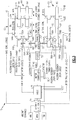
- FIG. 4 another integrated VAFN-TRAS Actuation System 17 is schematically shown and includes actuators 96A-B coupled to both a right side TRAS cowl 52A and VAFN surface 54 A and actuators 98A-B coupled to both a left side TRAS cowl 52B and a VAFN surface 54B.
- Each of the actuators 96A-B, 98A-B include a selectively engageable drive that provides for selective actuation of the corresponding TRAS cowl 52A-B and VAFN surface 54A-B.
- the actuators 96A-B, 98A-B comprises a mechanical drive such as a ball screw that moves the corresponding surfaces through a corresponding locking lug.
- the actuators 96A-B, 98A-B includes selectively drivable lugs 100A-B, 104A-B coupled to the corresponding cowl 52A-B. Additional lugs 102A-B, 106A-B are coupled to the corresponding surfaces 54A-B. Each of the lugs 100A-B, 104A-B, can be selectively engaged or disengaged from the corresponding actuator 96A-B, 98A-B to provide selective independent movement of the cowls 52A-B and surfaces 54A-B.
- Each of the actuators 96A-B, 98A-B include a lock 108, 110 that provides for engagement of the corresponding lug 100A-B, 104A-B.
- the locks 108 correspond with the "A" actuator 96A, 98A on each of the right and left sides 60, 62.
- the locks 110 correspond with the "B” actuator 96B, 98B on the right and left sides 60, 62.
- the "A" locks 108 are controlled together through a combination of the aircraft electronics 88 and the FADEC 76 through a lock contactor 118.
- the "B” locks are controlled separately by the motor controller 74.
- the cowl locks 94A-B is controlled by the FADEC 76.
- the different control paths for the "A" locks 108 and the "B” locks 110 provides a desired redundancy that prevents undesired or unauthorized operation of the thrust reverser functions.
- the example PDU 68 is driven by a first motor114 and a second motor 116.
- the use of two motors provides a further redundancy to assure reliable operation.
- the motors may drive separate portions of the PDU 68 during different phase of operation of the integrated VAFN-TRAS actuation system 17.
- the first motor 114 may operate in response to operation a movement of the surfaces 54A-B.
- the second motor 116 may be further engaged in response to movement of the cowls 52A-B to provide additional power as may be required.
- many different motor configurations for driving the PDU 68 could be utilized and are within the contemplation of this disclosure.
Landscapes
- Engineering & Computer Science (AREA)
- Chemical & Material Sciences (AREA)
- Combustion & Propulsion (AREA)
- Mechanical Engineering (AREA)
- General Engineering & Computer Science (AREA)
- Retarders (AREA)
- Control Of Turbines (AREA)
- Feedback Control In General (AREA)
- Spray Control Apparatus (AREA)
Claims (9)
- Gondelanordnung (14) für einen Luftfahrzeugmotor (10), umfassend:eine Fandüse (46), die zwischen einer ersten Position und einer zweiten Position bewegbar ist, um einen Ablassstrombereich (48) zu definieren;eine Schubumkehrvorrichtung (50), die zwischen einer verstauten Position und einer betätigten Position bewegbar ist, um Ablassstrom in einer Schubumkehrrichtung abzulenken, wobei die Fandüse für Bewegung unabhängig von Bewegung der Schubumkehrvorrichtung konfiguriert ist;ein erstes Stellglied (56A, 58A; 96A; 98A), um sowohl die Fandüse als auch die Schubumkehrvorrichtung zu bewegen, wobei das erste Stellglied einen ersten Abschnitt (80), der konfiguriert ist, um die Fandüse zu bewegen, und einen zweiten Abschnitt (82), der konfiguriert ist, um die Schubumkehrvorrichtung zu bewegen, beinhaltet;eine Leistungsantriebseinheit (68) zum Übertragen von Leistung von einem Motor auf das erste Stellglied; undeine Haubenverriegelung (94A-B), die mit der Schubumkehrvorrichtung in Eingriff ist, um Bewegung der Schubumkehrvorrichtung in einem verriegelten Zustand zu verhindern und Bewegung der Schubumkehrvorrichtung in einem entriegelten Zustand zu ermöglichen,gekennzeichnet durch:ein zweites Stellglied (56B; 58B; 96B; 98B), um sowohl die Fandüse als auch die Schubumkehrvorrichtung zu bewegen, wobei das zweite Stellglied einen ersten Abschnitt (80), der konfiguriert ist, um die Fandüse zu bewegen, und einen zweiten Abschnitt (82), der konfiguriert ist, um die Schubumkehrvorrichtung zu bewegen, beinhaltet, wobei die Leistungsantriebseinheit ferner Leistung von dem Motor auf das zweite Stellglied überträgt; undeine erste Verriegelung (84A; 86A; 108), die an dem ersten Stellglied angeordnet ist, und eine zweite Verriegelung (84B; 86B; 110), die an dem zweiten Stellglied angeordnet ist, wobei die erste und zweite Verriegelung konfiguriert sind, um Bewegung der Schubumkehrvorrichtung in einem verriegelten Zustand zu verhindern und Bewegung der Schubumkehrvorrichtung in einem entriegelten Zustand zu ermöglichen, wobei die erste Verriegelung und die zweite Verriegelung konfiguriert sind, um die zweiten Abschnitte der jeweiligen Stellglieder gegen Bewegung in einem verriegelten Zustand zu verriegeln und um Bewegung der ersten Abschnitte der jeweiligen Stellglieder in einem verriegelten Zustand zu ermöglichen und Bewegung sowohl der ersten Abschnitte als auch der zweiten Abschnitte der jeweiligen Stellglieder in einem entriegelten Zustand zu ermöglichen.
- Anordnung nach Anspruch 1, beinhaltend eine Steuerung (76) zum Steuern des Betriebs der ersten Verriegelung, der zweiten Verriegelung und der Haubenverriegelung, sodass jede von der ersten Verriegelung, der zweiten Verriegelung und der Haubenverriegelung unabhängig Bewegung der Schubumkehrvorrichtung in die betätigte Position verhindern kann.
- Anordnung nach einem vorhergehenden Anspruch, wobei die Fandüse eine erste Fandüse und eine zweite Fandüse umfasst und die Schubumkehrvorrichtung eine erste Schubumkehrvorrichtung und eine zweite Schubumkehrvorrichtung umfasst.
- Gasturbinenmotorsystem (10), umfassend:einen Fan (34);die Gondelanordnung nach einem vorhergehenden Anspruch, eine Gondel beinhaltend, die um den Fan herum angeordnet ist;einen Gasturbinenmotorkern (16), der einen Verdichter (28), eine Brennkammer (32) und eine Turbine (30) zumindest teilweise innerhalb der Gondel aufweist; undeinen Fanumgehungskanal (40) stromabwärts des Fans zwischen dem Gasturbinenmotorkern und der Gondel,wobei die Fandüse bewegbar ist, um den Ablassstrombereich durch den Fanumgehungskanal einzustellen.
- Gasturbinenmotorsystem nach Anspruch 4, wobei sowohl die Fandüse als auch die Schubumkehrvorrichtung eine erste Seite und eine zweite Seite umfassen, wobei die erste Seite und die zweite Seite jeweils ein erstes und zweites Stellglied umfassen, die an eine Fandüse und eine Schubumkehrvorrichtung sowohl auf der ersten Seite als auch der zweiten Seite gekoppelt sind.
- Gasturbinenmotorsystem nach Anspruch 5, wobei die Leistungsantriebseinheit konfiguriert ist, um jedes von den Stellgliedern der ersten Seite und den Stellgliedern der zweiten Seite durch ein entsprechendes erstes und zweites Getriebe anzutreiben.
- Verfahren zum Bedienen von bewegbaren Strukturen einer Gondel (38), umfassend:Koppeln einer Fandüse (46), die bewegbar ist, um einen Ablassstrombereich (48) durch einen Fanumgehungskanal (44) einzustellen, an einen ersten Abschnitt (80) eines ersten Stellgliedes (56A; 58A; 96A; 98A) und einen ersten Abschnitt eines zweiten Stellgliedes (56B; 58B; 96B; 98B);Koppeln einer Schubumkehrvorrichtung (50), die zwischen einer verstauten Position und einer betätigten Position bewegbar ist, um Ablassstrom in einer Schubumkehrrichtung abzulenken, an einen zweiten Abschnitt (82) des ersten Stellgliedes und einen zweiten Abschnitt (82) des zweiten Stellgliedes, wobei die Fandüse unabhängig von der Schubumkehrvorrichtung bewegbar ist;Bewegen der Fandüse mit den ersten Abschnitten der ersten und zweiten Stellglieder in eine gewünschte Position zwischen einer verstauten und offenen Position;Lösen einer Haubenverriegelung (94A-B), die mit der Schubumkehrvorrichtung in Eingriff ist, die Bewegung der Schubumkehrvorrichtung und der zweiten Abschnitte der ersten und zweiten Stellglieder verhindert;Lösen einer ersten Verriegelung (84A, 86A, 108) und einer zweiten Verriegelung (84B; 86B; 110), die jeweils an dem ersten Stellglied und dem zweiten Stellglied angeordnet sind, die Bewegung der Schubumkehrvorrichtung und der zweiten Abschnitte jeweils des ersten Stellgliedes und des zweiten Stellgliedes verhindern;Bewegen der Schubumkehrvorrichtung mit den zweiten Abschnitten der ersten und zweiten Stellglieder in eine gewünschte Position zwischen einer verstauten und offenen Position unabhängig von der Fandüse; undAntreiben sowohl der ersten Abschnitte der ersten und zweiten Stellglieder als auch der zweiten Abschnitte der ersten und zweiten Stellglieder mit einer Leistungsantriebseinheit (68), die Leistung von einem gemeinsamen Motor (72) überträgt.
- Verfahren nach Anspruch 7, wobei die erste Verriegelung und die zweite Verriegelung konfiguriert sind, um die zweiten Abschnitte der ersten und zweiten Stellglieder in Eingriff zu nehmen und zu trennen.
- Verfahren nach Anspruch 7 oder 8, beinhaltend den Schritt des Verhinderns von Bewegung der Schubumkehrvorrichtung in die offene Position als Reaktion darauf, dass sich eine von der ersten Verriegelung, der zweiten Verriegelung und der Haubenverriegelung in einem verriegelten Zustand befindet.
Applications Claiming Priority (2)
| Application Number | Priority Date | Filing Date | Title |
|---|---|---|---|
| US201161504375P | 2011-07-05 | 2011-07-05 | |
| US13/252,305 US8615982B2 (en) | 2011-07-05 | 2011-10-04 | Integrated electric variable area fan nozzle thrust reversal actuation system |
Publications (3)
| Publication Number | Publication Date |
|---|---|
| EP2543863A2 EP2543863A2 (de) | 2013-01-09 |
| EP2543863A3 EP2543863A3 (de) | 2016-12-07 |
| EP2543863B1 true EP2543863B1 (de) | 2019-06-19 |
Family
ID=46420012
Family Applications (1)
| Application Number | Title | Priority Date | Filing Date |
|---|---|---|---|
| EP12175012.9A Not-in-force EP2543863B1 (de) | 2011-07-05 | 2012-07-04 | Integriertes Betätigungssystem einer Fandüse variabler Geometrie und Schubumkehrvorrichtung sowie Verfahren hierfür |
Country Status (4)
| Country | Link |
|---|---|
| US (1) | US8615982B2 (de) |
| EP (1) | EP2543863B1 (de) |
| CN (1) | CN102865156A (de) |
| RU (1) | RU2012127886A (de) |
Families Citing this family (28)
| Publication number | Priority date | Publication date | Assignee | Title |
|---|---|---|---|---|
| US8713911B2 (en) * | 2010-12-15 | 2014-05-06 | Woodward Hrt, Inc. | System and method for operating a thrust reverser for a turbofan propulsion system |
| FR2989429B1 (fr) * | 2012-04-17 | 2014-05-16 | Airbus Operations Sas | Dispositif de commande d'une tuyere a section variable d'un aeronef |
| US20150090810A1 (en) * | 2013-02-11 | 2015-04-02 | Spirit Aerosystems, Inc. | Thrust reverser hydraulic actuation system with servo synchronization |
| FR3005489B1 (fr) * | 2013-05-07 | 2017-03-17 | Airbus Operations Sas | Dispositif de commande d'une tuyere a section variable d'un aeronef |
| FR3005488B1 (fr) * | 2013-05-07 | 2015-05-29 | Airbus Operations Sas | Dispositif de commande d'une tuyere a section variable d'un aeronef |
| FR3005697B1 (fr) * | 2013-05-14 | 2017-08-25 | Aircelle Sa | Ensemble propulsif pour aeronef |
| FR3006817B1 (fr) * | 2013-06-10 | 2016-11-18 | Hispano Suiza Sa | Dispositif et procede d'assistance d'un systeme de generation electrique d'un aeronef |
| FR3010387B1 (fr) * | 2013-09-10 | 2015-10-09 | Airbus Operations Sas | Aeronef comprenant un dispositif de commande d'une tuyere a section variable alimente par deux alimentations electriques independantes |
| US9863367B2 (en) | 2013-11-01 | 2018-01-09 | The Boeing Company | Fan nozzle drive systems that lock thrust reversers |
| RU2557871C1 (ru) * | 2014-05-14 | 2015-07-27 | Сергей Михайлович Мужичек | Устройство для предотвращения выкатывания воздушных судов за пределы взлетно-посадочной полосы |
| FR3029985B1 (fr) * | 2014-12-11 | 2017-01-27 | Aircelle Sa | Dispositif de controle d’une tuyere a section variable et son procede de mise en œuvre |
| JP6554282B2 (ja) * | 2014-12-24 | 2019-07-31 | 川崎重工業株式会社 | 航空機用エンジン装置 |
| US10208708B2 (en) | 2015-01-29 | 2019-02-19 | Rohr, Inc. | Translating cascade hidden blocker door thrust reverser |
| US10473057B2 (en) | 2015-12-14 | 2019-11-12 | Rohr, Inc. | Thrust reverser system with translating elements |
| US9976696B2 (en) | 2016-06-21 | 2018-05-22 | Rohr, Inc. | Linear actuator with multi-degree of freedom mounting structure |
| US20180128206A1 (en) * | 2016-11-09 | 2018-05-10 | General Electric Company | Gas turbine engine |
| US10227951B2 (en) * | 2017-02-02 | 2019-03-12 | Woodward, Inc. | Limited flow thrust reverser actuating |
| EP3450736B1 (de) | 2017-09-04 | 2024-11-20 | Brandenburgische Technische Universität Cottbus-Senftenberg | Strahltriebwerk mit schubdüse variabler geometrie sowie schubumkehrvorrichtung |
| US10731738B2 (en) | 2017-11-27 | 2020-08-04 | Rohr, Inc. | Kinematic system with motion control device |
| EP3572659B1 (de) * | 2018-05-25 | 2024-09-25 | Goodrich Actuation Systems Limited | Schubumkehrerbetätigungssystem |
| CN108956270B (zh) * | 2018-07-25 | 2020-10-09 | 黄传道 | 一种利用反推减少惯性作用的橡胶条拉伸检测装置 |
| CN112824665B (zh) * | 2019-11-21 | 2022-02-18 | 中国航发商用航空发动机有限责任公司 | 外涵喷管驱动装置、组件以及气流输出面积调整方法 |
| US11597508B2 (en) | 2021-05-13 | 2023-03-07 | Beta Air, Llc | Aircraft having reverse thrust capabilities |
| CN113217223B (zh) * | 2020-01-21 | 2022-07-08 | 中国航发商用航空发动机有限责任公司 | 反推装置、航空发动机短舱、飞机及反推装置的控制方法 |
| CN112945563B (zh) * | 2021-02-05 | 2022-11-22 | 中国航发沈阳发动机研究所 | 一种发动机性能录取试验防反推排气装置 |
| US12486029B2 (en) | 2021-05-13 | 2025-12-02 | Beta Air Llc | Aircraft having reverse thrust capabilities |
| CN115535264B (zh) * | 2021-06-29 | 2025-11-25 | 中国航发商用航空发动机有限责任公司 | 反推装置锁定机构及包括其的航空发动机 |
| FR3129377B1 (fr) * | 2021-11-25 | 2023-11-24 | Safran | Fourniture d’energie dans un aeronef utilisant un contrôle de statisme |
Family Cites Families (32)
| Publication number | Priority date | Publication date | Assignee | Title |
|---|---|---|---|---|
| US3391898A (en) * | 1965-12-29 | 1968-07-09 | United Aircraft Corp | Actuating mechanism |
| US3779010A (en) | 1972-08-17 | 1973-12-18 | Gen Electric | Combined thrust reversing and throat varying mechanism for a gas turbine engine |
| US4373328A (en) | 1980-10-22 | 1983-02-15 | United Technologies Corporation | Thrust reverser |
| US4527391A (en) | 1982-09-30 | 1985-07-09 | United Technologies Corporation | Thrust reverser |
| FR2622929A1 (fr) * | 1987-11-05 | 1989-05-12 | Hispano Suiza Sa | Inverseur de poussee de turboreacteur a grilles,a section variable d'ejection |
| CA1326767C (en) * | 1988-10-27 | 1994-02-08 | Etienne Fage | Jet engine provided with a thrust reverser |
| US5181676A (en) | 1992-01-06 | 1993-01-26 | Lair Jean Pierre | Thrust reverser integrating a variable exhaust area nozzle |
| FR2691508B1 (fr) * | 1992-05-20 | 1994-07-08 | Snecma | Verin a fluide sous pression et tuyere a section variable en faisant application. |
| RU2120559C1 (ru) * | 1992-09-21 | 1998-10-20 | Дзе Боинг Компани | Механический стопор для реверсера тяги реактивного двигателя |
| US5778659A (en) | 1994-10-20 | 1998-07-14 | United Technologies Corporation | Variable area fan exhaust nozzle having mechanically separate sleeve and thrust reverser actuation systems |
| US5575147A (en) | 1994-12-22 | 1996-11-19 | United Technologies Corporation | Compact thrust reverser |
| US5655360A (en) * | 1995-05-31 | 1997-08-12 | General Electric Company | Thrust reverser with variable nozzle |
| GB9825651D0 (en) * | 1998-11-23 | 1999-01-13 | Lucas Ind Plc | Actuator |
| US6170254B1 (en) | 1998-12-18 | 2001-01-09 | Rohr, Inc. | Translating sleeve for cascade type thrust reversing system for fan gas turbine engine for an aircraft |
| GB2372729A (en) * | 2001-03-03 | 2002-09-04 | Rolls Royce Plc | Thrust reverser arrangement with means for reducing noise |
| FR2846377B1 (fr) * | 2002-10-25 | 2006-06-30 | Hispano Suiza Sa | Inverseur de poussee electromecanique pour turboreacteur a controle permanent de position |
| FR2846378B1 (fr) * | 2002-10-25 | 2006-06-30 | Hispano Suiza Sa | Inverseur de poussee electromecanique pour turboreacteur a synchronisation des dispositifs de verrouillage |
| WO2008045072A1 (en) | 2006-10-12 | 2008-04-17 | United Technologies Corporation | Dual function cascade integrated variable area fan nozzle and thrust reverser |
| EP2074304B1 (de) * | 2006-10-12 | 2015-03-25 | United Technologies Corporation | Gasturbinentriebwerk mit Dreifachkörper-Gebläsedüse mit variablem Querschnitt und Schubumkehrvorrichtung |
| US7946105B2 (en) * | 2006-11-02 | 2011-05-24 | Honeywell International Inc. | Bi-directional locking ring assembly for aircraft thrust reverser manual drive unit |
| US7886518B2 (en) | 2006-11-14 | 2011-02-15 | General Electric Company | Turbofan engine cowl assembly and method of operating the same |
| GB2446441A (en) * | 2007-02-06 | 2008-08-13 | Goodrich Actuation Systems Ltd | Dual cylinder Actuator Arrangement for aeroengine nozzle and reverser |
| GB0706270D0 (en) * | 2007-03-30 | 2007-05-09 | Goodrich Actuation Systems Ltd | Actuator arrangement |
| FR2917788B1 (fr) * | 2007-06-19 | 2009-07-24 | Aircelle Sa | Actionneur double action a effet programme |
| FR2922058B1 (fr) * | 2007-10-04 | 2009-12-04 | Aircelle Sa | Actionneur lineaire telescopique pour deplacer un premier et un second elements relativement a un element fixe |
| FR2921976B1 (fr) * | 2007-10-08 | 2009-12-04 | Aircelle Sa | Actionneur pour structure mobile de nacelle d'aeronef, et nacelle comprenant au moins un tel actionneur |
| US7735778B2 (en) | 2007-11-16 | 2010-06-15 | Pratt & Whitney Canada Corp. | Pivoting fairings for a thrust reverser |
| FR2944564B1 (fr) * | 2009-04-16 | 2011-04-22 | Aircelle Sa | Systeme de controle pour nacelle de turboreacteur |
| GB201002315D0 (en) * | 2010-02-11 | 2010-03-31 | Goodrich Actuation Systems Ltd | Control system |
| US8978356B2 (en) * | 2010-12-03 | 2015-03-17 | The Boeing Company | Thrust reverser and variable area fan nozzle actuation system and method |
| US9416751B2 (en) * | 2010-12-07 | 2016-08-16 | Hamilton Sundstrand Corporation | Actuation system |
| US20130146708A1 (en) * | 2011-12-08 | 2013-06-13 | Honeywell International Inc. | Case assemblies with common controls |
-
2011
- 2011-10-04 US US13/252,305 patent/US8615982B2/en not_active Expired - Fee Related
-
2012
- 2012-07-04 EP EP12175012.9A patent/EP2543863B1/de not_active Not-in-force
- 2012-07-05 CN CN2012102310234A patent/CN102865156A/zh active Pending
- 2012-07-05 RU RU2012127886/11A patent/RU2012127886A/ru not_active Application Discontinuation
Non-Patent Citations (1)
| Title |
|---|
| None * |
Also Published As
| Publication number | Publication date |
|---|---|
| EP2543863A3 (de) | 2016-12-07 |
| CN102865156A (zh) | 2013-01-09 |
| EP2543863A2 (de) | 2013-01-09 |
| US20130008145A1 (en) | 2013-01-10 |
| US8615982B2 (en) | 2013-12-31 |
| RU2012127886A (ru) | 2014-01-10 |
Similar Documents
| Publication | Publication Date | Title |
|---|---|---|
| EP2543863A2 (de) | Integriertes Betätigungssystem einer Fandüse variabler Geometrie und Schubumkehrvorrichtung | |
| EP1554484B1 (de) | Schubumkehrstellantrieb mit automatischem entriegelungsschutzmechanismus | |
| EP2050948B1 (de) | Eine Vorrichtung von einem Gasturbinentriebwerk mit einer Schubdüse mit veränderlichem Querschnitt und ein Steuerungsverfahren für diese Düse | |
| EP2074304B1 (de) | Gasturbinentriebwerk mit Dreifachkörper-Gebläsedüse mit variablem Querschnitt und Schubumkehrvorrichtung | |
| EP2074288B1 (de) | Mantelstromtriebwerk mit gebläsedüse mit variablem querschnitt und niedrigwellengenerator zur notstromerzeugung und verfahren zur notstromversorgung | |
| US8104262B2 (en) | Dual function cascade integrated variable area fan nozzle and thrust reverser | |
| EP1386072B1 (de) | Kontrollvorrichtung für die betätigung von schubumkehrvorrichtungen an strahltriebwerken | |
| EP2466101B1 (de) | System und Verfahren zum Betreiben einer Schubumkehrvorrichtung für ein Turbofantriebwerk | |
| US6598386B2 (en) | Jet engine thrust reverser system having torque limited synchronization | |
| US6935097B2 (en) | Lock assembly that inhibits thrust reverser movement at or near the stowed position | |
| EP2955359B1 (de) | Mantelstrom-schubumkehrsystem | |
| CN102395509B (zh) | 用于涡轮喷气发动机机舱的活动板的致动器系统 | |
| US20100043390A1 (en) | Controlling ice buildup on aircraft engine and nacelle static and rotating components | |
| EP2074301B1 (de) | Fan-triebwerk mit schubdüsenkontrolle für start und landung | |
| EP2074308B1 (de) | Integrierter mechanismus aus einer düse mit variablem querschnitt und schubumkehrvorrichtung | |
| US20110296812A1 (en) | Thrust reverser actuation system architecture |
Legal Events
| Date | Code | Title | Description |
|---|---|---|---|
| PUAI | Public reference made under article 153(3) epc to a published international application that has entered the european phase |
Free format text: ORIGINAL CODE: 0009012 |
|
| AK | Designated contracting states |
Kind code of ref document: A2 Designated state(s): AL AT BE BG CH CY CZ DE DK EE ES FI FR GB GR HR HU IE IS IT LI LT LU LV MC MK MT NL NO PL PT RO RS SE SI SK SM TR |
|
| AX | Request for extension of the european patent |
Extension state: BA ME |
|
| PUAL | Search report despatched |
Free format text: ORIGINAL CODE: 0009013 |
|
| AK | Designated contracting states |
Kind code of ref document: A3 Designated state(s): AL AT BE BG CH CY CZ DE DK EE ES FI FR GB GR HR HU IE IS IT LI LT LU LV MC MK MT NL NO PL PT RO RS SE SI SK SM TR |
|
| AX | Request for extension of the european patent |
Extension state: BA ME |
|
| RIC1 | Information provided on ipc code assigned before grant |
Ipc: F02K 1/76 20060101ALI20161102BHEP Ipc: F02K 1/12 20060101ALI20161102BHEP Ipc: F02K 1/72 20060101AFI20161102BHEP |
|
| STAA | Information on the status of an ep patent application or granted ep patent |
Free format text: STATUS: REQUEST FOR EXAMINATION WAS MADE |
|
| 17P | Request for examination filed |
Effective date: 20170607 |
|
| RBV | Designated contracting states (corrected) |
Designated state(s): AL AT BE BG CH CY CZ DE DK EE ES FI FR GB GR HR HU IE IS IT LI LT LU LV MC MK MT NL NO PL PT RO RS SE SI SK SM TR |
|
| GRAP | Despatch of communication of intention to grant a patent |
Free format text: ORIGINAL CODE: EPIDOSNIGR1 |
|
| STAA | Information on the status of an ep patent application or granted ep patent |
Free format text: STATUS: GRANT OF PATENT IS INTENDED |
|
| INTG | Intention to grant announced |
Effective date: 20181129 |
|
| GRAS | Grant fee paid |
Free format text: ORIGINAL CODE: EPIDOSNIGR3 |
|
| GRAA | (expected) grant |
Free format text: ORIGINAL CODE: 0009210 |
|
| STAA | Information on the status of an ep patent application or granted ep patent |
Free format text: STATUS: THE PATENT HAS BEEN GRANTED |
|
| AK | Designated contracting states |
Kind code of ref document: B1 Designated state(s): AL AT BE BG CH CY CZ DE DK EE ES FI FR GB GR HR HU IE IS IT LI LT LU LV MC MK MT NL NO PL PT RO RS SE SI SK SM TR |
|
| REG | Reference to a national code |
Ref country code: GB Ref legal event code: FG4D |
|
| REG | Reference to a national code |
Ref country code: CH Ref legal event code: EP |
|
| REG | Reference to a national code |
Ref country code: IE Ref legal event code: FG4D |
|
| REG | Reference to a national code |
Ref country code: DE Ref legal event code: R096 Ref document number: 602012061090 Country of ref document: DE |
|
| REG | Reference to a national code |
Ref country code: AT Ref legal event code: REF Ref document number: 1145831 Country of ref document: AT Kind code of ref document: T Effective date: 20190715 |
|
| REG | Reference to a national code |
Ref country code: NL Ref legal event code: MP Effective date: 20190619 |
|
| PG25 | Lapsed in a contracting state [announced via postgrant information from national office to epo] |
Ref country code: SE Free format text: LAPSE BECAUSE OF FAILURE TO SUBMIT A TRANSLATION OF THE DESCRIPTION OR TO PAY THE FEE WITHIN THE PRESCRIBED TIME-LIMIT Effective date: 20190619 Ref country code: HR Free format text: LAPSE BECAUSE OF FAILURE TO SUBMIT A TRANSLATION OF THE DESCRIPTION OR TO PAY THE FEE WITHIN THE PRESCRIBED TIME-LIMIT Effective date: 20190619 Ref country code: LT Free format text: LAPSE BECAUSE OF FAILURE TO SUBMIT A TRANSLATION OF THE DESCRIPTION OR TO PAY THE FEE WITHIN THE PRESCRIBED TIME-LIMIT Effective date: 20190619 Ref country code: AL Free format text: LAPSE BECAUSE OF FAILURE TO SUBMIT A TRANSLATION OF THE DESCRIPTION OR TO PAY THE FEE WITHIN THE PRESCRIBED TIME-LIMIT Effective date: 20190619 Ref country code: NO Free format text: LAPSE BECAUSE OF FAILURE TO SUBMIT A TRANSLATION OF THE DESCRIPTION OR TO PAY THE FEE WITHIN THE PRESCRIBED TIME-LIMIT Effective date: 20190919 Ref country code: FI Free format text: LAPSE BECAUSE OF FAILURE TO SUBMIT A TRANSLATION OF THE DESCRIPTION OR TO PAY THE FEE WITHIN THE PRESCRIBED TIME-LIMIT Effective date: 20190619 |
|
| REG | Reference to a national code |
Ref country code: LT Ref legal event code: MG4D |
|
| PG25 | Lapsed in a contracting state [announced via postgrant information from national office to epo] |
Ref country code: BG Free format text: LAPSE BECAUSE OF FAILURE TO SUBMIT A TRANSLATION OF THE DESCRIPTION OR TO PAY THE FEE WITHIN THE PRESCRIBED TIME-LIMIT Effective date: 20190919 Ref country code: LV Free format text: LAPSE BECAUSE OF FAILURE TO SUBMIT A TRANSLATION OF THE DESCRIPTION OR TO PAY THE FEE WITHIN THE PRESCRIBED TIME-LIMIT Effective date: 20190619 Ref country code: RS Free format text: LAPSE BECAUSE OF FAILURE TO SUBMIT A TRANSLATION OF THE DESCRIPTION OR TO PAY THE FEE WITHIN THE PRESCRIBED TIME-LIMIT Effective date: 20190619 Ref country code: GR Free format text: LAPSE BECAUSE OF FAILURE TO SUBMIT A TRANSLATION OF THE DESCRIPTION OR TO PAY THE FEE WITHIN THE PRESCRIBED TIME-LIMIT Effective date: 20190920 |
|
| REG | Reference to a national code |
Ref country code: AT Ref legal event code: MK05 Ref document number: 1145831 Country of ref document: AT Kind code of ref document: T Effective date: 20190619 |
|
| PG25 | Lapsed in a contracting state [announced via postgrant information from national office to epo] |
Ref country code: EE Free format text: LAPSE BECAUSE OF FAILURE TO SUBMIT A TRANSLATION OF THE DESCRIPTION OR TO PAY THE FEE WITHIN THE PRESCRIBED TIME-LIMIT Effective date: 20190619 Ref country code: AT Free format text: LAPSE BECAUSE OF FAILURE TO SUBMIT A TRANSLATION OF THE DESCRIPTION OR TO PAY THE FEE WITHIN THE PRESCRIBED TIME-LIMIT Effective date: 20190619 Ref country code: NL Free format text: LAPSE BECAUSE OF FAILURE TO SUBMIT A TRANSLATION OF THE DESCRIPTION OR TO PAY THE FEE WITHIN THE PRESCRIBED TIME-LIMIT Effective date: 20190619 Ref country code: CZ Free format text: LAPSE BECAUSE OF FAILURE TO SUBMIT A TRANSLATION OF THE DESCRIPTION OR TO PAY THE FEE WITHIN THE PRESCRIBED TIME-LIMIT Effective date: 20190619 Ref country code: RO Free format text: LAPSE BECAUSE OF FAILURE TO SUBMIT A TRANSLATION OF THE DESCRIPTION OR TO PAY THE FEE WITHIN THE PRESCRIBED TIME-LIMIT Effective date: 20190619 Ref country code: SK Free format text: LAPSE BECAUSE OF FAILURE TO SUBMIT A TRANSLATION OF THE DESCRIPTION OR TO PAY THE FEE WITHIN THE PRESCRIBED TIME-LIMIT Effective date: 20190619 Ref country code: PT Free format text: LAPSE BECAUSE OF FAILURE TO SUBMIT A TRANSLATION OF THE DESCRIPTION OR TO PAY THE FEE WITHIN THE PRESCRIBED TIME-LIMIT Effective date: 20191021 |
|
| PG25 | Lapsed in a contracting state [announced via postgrant information from national office to epo] |
Ref country code: IS Free format text: LAPSE BECAUSE OF FAILURE TO SUBMIT A TRANSLATION OF THE DESCRIPTION OR TO PAY THE FEE WITHIN THE PRESCRIBED TIME-LIMIT Effective date: 20191019 Ref country code: SM Free format text: LAPSE BECAUSE OF FAILURE TO SUBMIT A TRANSLATION OF THE DESCRIPTION OR TO PAY THE FEE WITHIN THE PRESCRIBED TIME-LIMIT Effective date: 20190619 Ref country code: ES Free format text: LAPSE BECAUSE OF FAILURE TO SUBMIT A TRANSLATION OF THE DESCRIPTION OR TO PAY THE FEE WITHIN THE PRESCRIBED TIME-LIMIT Effective date: 20190619 Ref country code: IT Free format text: LAPSE BECAUSE OF FAILURE TO SUBMIT A TRANSLATION OF THE DESCRIPTION OR TO PAY THE FEE WITHIN THE PRESCRIBED TIME-LIMIT Effective date: 20190619 |
|
| REG | Reference to a national code |
Ref country code: CH Ref legal event code: PL |
|
| PG25 | Lapsed in a contracting state [announced via postgrant information from national office to epo] |
Ref country code: MC Free format text: LAPSE BECAUSE OF FAILURE TO SUBMIT A TRANSLATION OF THE DESCRIPTION OR TO PAY THE FEE WITHIN THE PRESCRIBED TIME-LIMIT Effective date: 20190619 Ref country code: TR Free format text: LAPSE BECAUSE OF FAILURE TO SUBMIT A TRANSLATION OF THE DESCRIPTION OR TO PAY THE FEE WITHIN THE PRESCRIBED TIME-LIMIT Effective date: 20190619 |
|
| REG | Reference to a national code |
Ref country code: BE Ref legal event code: MM Effective date: 20190731 |
|
| PG25 | Lapsed in a contracting state [announced via postgrant information from national office to epo] |
Ref country code: DK Free format text: LAPSE BECAUSE OF FAILURE TO SUBMIT A TRANSLATION OF THE DESCRIPTION OR TO PAY THE FEE WITHIN THE PRESCRIBED TIME-LIMIT Effective date: 20190619 Ref country code: PL Free format text: LAPSE BECAUSE OF FAILURE TO SUBMIT A TRANSLATION OF THE DESCRIPTION OR TO PAY THE FEE WITHIN THE PRESCRIBED TIME-LIMIT Effective date: 20190619 |
|
| PG25 | Lapsed in a contracting state [announced via postgrant information from national office to epo] |
Ref country code: IS Free format text: LAPSE BECAUSE OF FAILURE TO SUBMIT A TRANSLATION OF THE DESCRIPTION OR TO PAY THE FEE WITHIN THE PRESCRIBED TIME-LIMIT Effective date: 20200224 Ref country code: LU Free format text: LAPSE BECAUSE OF NON-PAYMENT OF DUE FEES Effective date: 20190704 Ref country code: CH Free format text: LAPSE BECAUSE OF NON-PAYMENT OF DUE FEES Effective date: 20190731 Ref country code: LI Free format text: LAPSE BECAUSE OF NON-PAYMENT OF DUE FEES Effective date: 20190731 Ref country code: BE Free format text: LAPSE BECAUSE OF NON-PAYMENT OF DUE FEES Effective date: 20190731 |
|
| REG | Reference to a national code |
Ref country code: DE Ref legal event code: R097 Ref document number: 602012061090 Country of ref document: DE |
|
| PLBE | No opposition filed within time limit |
Free format text: ORIGINAL CODE: 0009261 |
|
| STAA | Information on the status of an ep patent application or granted ep patent |
Free format text: STATUS: NO OPPOSITION FILED WITHIN TIME LIMIT |
|
| PG2D | Information on lapse in contracting state deleted |
Ref country code: IS |
|
| PG25 | Lapsed in a contracting state [announced via postgrant information from national office to epo] |
Ref country code: IE Free format text: LAPSE BECAUSE OF NON-PAYMENT OF DUE FEES Effective date: 20190704 |
|
| 26N | No opposition filed |
Effective date: 20200603 |
|
| PG25 | Lapsed in a contracting state [announced via postgrant information from national office to epo] |
Ref country code: SI Free format text: LAPSE BECAUSE OF FAILURE TO SUBMIT A TRANSLATION OF THE DESCRIPTION OR TO PAY THE FEE WITHIN THE PRESCRIBED TIME-LIMIT Effective date: 20190619 |
|
| PG25 | Lapsed in a contracting state [announced via postgrant information from national office to epo] |
Ref country code: CY Free format text: LAPSE BECAUSE OF FAILURE TO SUBMIT A TRANSLATION OF THE DESCRIPTION OR TO PAY THE FEE WITHIN THE PRESCRIBED TIME-LIMIT Effective date: 20190619 |
|
| PG25 | Lapsed in a contracting state [announced via postgrant information from national office to epo] |
Ref country code: MT Free format text: LAPSE BECAUSE OF FAILURE TO SUBMIT A TRANSLATION OF THE DESCRIPTION OR TO PAY THE FEE WITHIN THE PRESCRIBED TIME-LIMIT Effective date: 20190619 Ref country code: HU Free format text: LAPSE BECAUSE OF FAILURE TO SUBMIT A TRANSLATION OF THE DESCRIPTION OR TO PAY THE FEE WITHIN THE PRESCRIBED TIME-LIMIT; INVALID AB INITIO Effective date: 20120704 |
|
| PG25 | Lapsed in a contracting state [announced via postgrant information from national office to epo] |
Ref country code: MK Free format text: LAPSE BECAUSE OF FAILURE TO SUBMIT A TRANSLATION OF THE DESCRIPTION OR TO PAY THE FEE WITHIN THE PRESCRIBED TIME-LIMIT Effective date: 20190619 |
|
| P01 | Opt-out of the competence of the unified patent court (upc) registered |
Effective date: 20230522 |
|
| PGFP | Annual fee paid to national office [announced via postgrant information from national office to epo] |
Ref country code: FR Payment date: 20230621 Year of fee payment: 12 |
|
| PGFP | Annual fee paid to national office [announced via postgrant information from national office to epo] |
Ref country code: GB Payment date: 20230620 Year of fee payment: 12 |
|
| PGFP | Annual fee paid to national office [announced via postgrant information from national office to epo] |
Ref country code: DE Payment date: 20230620 Year of fee payment: 12 |
|
| REG | Reference to a national code |
Ref country code: DE Ref legal event code: R119 Ref document number: 602012061090 Country of ref document: DE |
|
| GBPC | Gb: european patent ceased through non-payment of renewal fee |
Effective date: 20240704 |
|
| PG25 | Lapsed in a contracting state [announced via postgrant information from national office to epo] |
Ref country code: DE Free format text: LAPSE BECAUSE OF NON-PAYMENT OF DUE FEES Effective date: 20250201 |
|
| PG25 | Lapsed in a contracting state [announced via postgrant information from national office to epo] |
Ref country code: FR Free format text: LAPSE BECAUSE OF NON-PAYMENT OF DUE FEES Effective date: 20240731 |
|
| PG25 | Lapsed in a contracting state [announced via postgrant information from national office to epo] |
Ref country code: GB Free format text: LAPSE BECAUSE OF NON-PAYMENT OF DUE FEES Effective date: 20240704 |