EP2543852A2 - Verfahren zur Bemessung der Leistung eines Hilfsgenerators - Google Patents
Verfahren zur Bemessung der Leistung eines Hilfsgenerators Download PDFInfo
- Publication number
- EP2543852A2 EP2543852A2 EP20120175299 EP12175299A EP2543852A2 EP 2543852 A2 EP2543852 A2 EP 2543852A2 EP 20120175299 EP20120175299 EP 20120175299 EP 12175299 A EP12175299 A EP 12175299A EP 2543852 A2 EP2543852 A2 EP 2543852A2
- Authority
- EP
- European Patent Office
- Prior art keywords
- egt
- apu
- performance
- sta
- tsr
- Prior art date
- Legal status (The legal status is an assumption and is not a legal conclusion. Google has not performed a legal analysis and makes no representation as to the accuracy of the status listed.)
- Granted
Links
Images


Classifications
-
- F—MECHANICAL ENGINEERING; LIGHTING; HEATING; WEAPONS; BLASTING
- F02—COMBUSTION ENGINES; HOT-GAS OR COMBUSTION-PRODUCT ENGINE PLANTS
- F02C—GAS-TURBINE PLANTS; AIR INTAKES FOR JET-PROPULSION PLANTS; CONTROLLING FUEL SUPPLY IN AIR-BREATHING JET-PROPULSION PLANTS
- F02C9/00—Controlling gas-turbine plants; Controlling fuel supply in air- breathing jet-propulsion plants
-
- B—PERFORMING OPERATIONS; TRANSPORTING
- B64—AIRCRAFT; AVIATION; COSMONAUTICS
- B64F—GROUND OR AIRCRAFT-CARRIER-DECK INSTALLATIONS SPECIALLY ADAPTED FOR USE IN CONNECTION WITH AIRCRAFT; DESIGNING, MANUFACTURING, ASSEMBLING, CLEANING, MAINTAINING OR REPAIRING AIRCRAFT, NOT OTHERWISE PROVIDED FOR; HANDLING, TRANSPORTING, TESTING OR INSPECTING AIRCRAFT COMPONENTS, NOT OTHERWISE PROVIDED FOR
- B64F5/00—Designing, manufacturing, assembling, cleaning, maintaining or repairing aircraft, not otherwise provided for; Handling, transporting, testing or inspecting aircraft components, not otherwise provided for
-
- B—PERFORMING OPERATIONS; TRANSPORTING
- B64—AIRCRAFT; AVIATION; COSMONAUTICS
- B64D—EQUIPMENT FOR FITTING IN OR TO AIRCRAFT; FLIGHT SUITS; PARACHUTES; ARRANGEMENT OR MOUNTING OF POWER PLANTS OR PROPULSION TRANSMISSIONS IN AIRCRAFT
- B64D41/00—Power installations for auxiliary purposes
-
- G—PHYSICS
- G01—MEASURING; TESTING
- G01M—TESTING STATIC OR DYNAMIC BALANCE OF MACHINES OR STRUCTURES; TESTING OF STRUCTURES OR APPARATUS, NOT OTHERWISE PROVIDED FOR
- G01M15/00—Testing of engines
- G01M15/14—Testing gas-turbine engines or jet-propulsion engines
-
- F—MECHANICAL ENGINEERING; LIGHTING; HEATING; WEAPONS; BLASTING
- F05—INDEXING SCHEMES RELATING TO ENGINES OR PUMPS IN VARIOUS SUBCLASSES OF CLASSES F01-F04
- F05D—INDEXING SCHEME FOR ASPECTS RELATING TO NON-POSITIVE-DISPLACEMENT MACHINES OR ENGINES, GAS-TURBINES OR JET-PROPULSION PLANTS
- F05D2220/00—Application
- F05D2220/50—Application for auxiliary power units (APU's)
-
- F—MECHANICAL ENGINEERING; LIGHTING; HEATING; WEAPONS; BLASTING
- F05—INDEXING SCHEMES RELATING TO ENGINES OR PUMPS IN VARIOUS SUBCLASSES OF CLASSES F01-F04
- F05D—INDEXING SCHEME FOR ASPECTS RELATING TO NON-POSITIVE-DISPLACEMENT MACHINES OR ENGINES, GAS-TURBINES OR JET-PROPULSION PLANTS
- F05D2260/00—Function
- F05D2260/80—Diagnostics
-
- F—MECHANICAL ENGINEERING; LIGHTING; HEATING; WEAPONS; BLASTING
- F05—INDEXING SCHEMES RELATING TO ENGINES OR PUMPS IN VARIOUS SUBCLASSES OF CLASSES F01-F04
- F05D—INDEXING SCHEME FOR ASPECTS RELATING TO NON-POSITIVE-DISPLACEMENT MACHINES OR ENGINES, GAS-TURBINES OR JET-PROPULSION PLANTS
- F05D2270/00—Control
- F05D2270/01—Purpose of the control system
- F05D2270/05—Purpose of the control system to affect the output of the engine
-
- F—MECHANICAL ENGINEERING; LIGHTING; HEATING; WEAPONS; BLASTING
- F05—INDEXING SCHEMES RELATING TO ENGINES OR PUMPS IN VARIOUS SUBCLASSES OF CLASSES F01-F04
- F05D—INDEXING SCHEME FOR ASPECTS RELATING TO NON-POSITIVE-DISPLACEMENT MACHINES OR ENGINES, GAS-TURBINES OR JET-PROPULSION PLANTS
- F05D2270/00—Control
- F05D2270/01—Purpose of the control system
- F05D2270/08—Purpose of the control system to produce clean exhaust gases
- F05D2270/083—Purpose of the control system to produce clean exhaust gases by monitoring combustion conditions
- F05D2270/0831—Purpose of the control system to produce clean exhaust gases by monitoring combustion conditions indirectly, at the exhaust
-
- F—MECHANICAL ENGINEERING; LIGHTING; HEATING; WEAPONS; BLASTING
- F05—INDEXING SCHEMES RELATING TO ENGINES OR PUMPS IN VARIOUS SUBCLASSES OF CLASSES F01-F04
- F05D—INDEXING SCHEME FOR ASPECTS RELATING TO NON-POSITIVE-DISPLACEMENT MACHINES OR ENGINES, GAS-TURBINES OR JET-PROPULSION PLANTS
- F05D2270/00—Control
- F05D2270/30—Control parameters, e.g. input parameters
- F05D2270/303—Temperature
-
- Y—GENERAL TAGGING OF NEW TECHNOLOGICAL DEVELOPMENTS; GENERAL TAGGING OF CROSS-SECTIONAL TECHNOLOGIES SPANNING OVER SEVERAL SECTIONS OF THE IPC; TECHNICAL SUBJECTS COVERED BY FORMER USPC CROSS-REFERENCE ART COLLECTIONS [XRACs] AND DIGESTS
- Y02—TECHNOLOGIES OR APPLICATIONS FOR MITIGATION OR ADAPTATION AGAINST CLIMATE CHANGE
- Y02T—CLIMATE CHANGE MITIGATION TECHNOLOGIES RELATED TO TRANSPORTATION
- Y02T50/00—Aeronautics or air transport
- Y02T50/60—Efficient propulsion technologies, e.g. for aircraft
Definitions
- the present application relates to a method for detecting the equipment's operation condition of an aircraft, in particular to a method for detecting the performance of an airborne auxiliary power unit.
- APU Airborne Auxiliary Power Unit
- the main function of the APU is to provide power and gas source, and a few APUs may provide additive thrust to the aircraft.
- the APU supplies power to start a main engine before the aircraft takes off from ground without need to rely on a ground power, gas source vehicle to start the aircraft.
- APU also supplies power and compressed air to ensure the lighting and air-conditioning in the cockpit and cabin.
- the APU can be used as a backup power. After landing, APU still supplies power to the lighting and air-conditioning.
- APU determines the operation stability thereof directly relates to flight cost and quality of service of the aircraft. Moreover, in the absence of guarantees of the ground power and gas source, once there is some malfunction of the APU, the result is that the aircraft cannot fly. At present, the troubleshooting and maintenance of the APU always are post-processing. However, among the equipments of aircraft, the maintenance cost of APU is higher. In addition, the price of parts of APU is higher, the cost for storing the spare parts is higher, and the repair cycle reaches up to 4-5 months. The stable operation of the APU cannot be guaranteed due to the post-processing maintenance. Moreover, the repair cycle is time-consuming, which directly causes the aircraft delays even to be grounded.
- a method for detecting performance of an APU comprising: obtaining EGT (Exhaust Gas Temperature), LCIT (Compressor Inlet Temperature), STA (Starting Time), TSR (Service Time) and PT (bleed air pressure); comparing respectively a difference of EGT and LCIT (i.e., EGT-LCIT), STA, TSR and PT with their respective threshold values; assigning weights to comparison results between the EGT-LCIT, STA, TSR and PT and the respective threshold values; and determining the performance of the APU based on the weighted comparison results between the EGT-LCIT, STA, TSR and PT and the respective threshold values.
- EGT Exhaust Gas Temperature
- LCIT Compressor Inlet Temperature
- STA Startting Time
- TSR Service Time
- PT bleed air pressure
- a method for detecting performance of an APU comprising: obtaining an operation parameter selected from a group composing of EGT (Exhaust Gas Temperature of APU), STA (Starting Time), PT (bleed air pressure) and an angle of IGV; determining whether the parameter changes significantly; determining the performance of the APU based on whether the parameter changes significantly.
- EGT Exhaust Gas Temperature of APU
- STA Startting Time
- PT bleed air pressure
- a method for detecting performance of an APU comprising: obtaining an operation parameter selected from a group composing of EGT (Exhaust Gas Temperature of APU) and PT (bleed air pressure); determining whether the parameter is close to its extreme value; and determining the performance of the APU based on whether the parameter is close to the extreme value.
- EGT Exhaust Gas Temperature of APU
- PT bleed air pressure
- Fig. 1 is a schematic illustrating a structure of the APU according to one embodiment of the present application.
- Fig. 2 is a schematic illustrating a structure of an inlet guide vane assembly according to one embodiment of the present application.
- Fig. 3 is a schematic illustrating a control structure of an inlet guide vane according to one embodiment of the present application.
- Fig. 4 is a schematic illustrating a curve of the change of the performance of the APU according to one embodiment of the present application.
- Fig. 5 is an example of A13 message of Airbus
- Fig. 6 is a flow chart illustrating a method for detecting the performance of the APU according to one embodiment of the present application.
- Fig. 7 is a flow chart illustrating a method for detecting the performance of the APU according to another one embodiment of the present application.
- FIG. 1 is a schematic illustrating a structure of the APU according to one embodiment of the present application.
- APU 100 includes a generator 102, a gearbox 104, a compressor portion 106 and a hot segment portion 108.
- the compressor portion 106 includes a front end axial flow centrifugal compressor 105 for generating high pressure air and outwardly providing bleed air.
- the hot segment portion 108 includes a rear end axial flow centrifugal compressor 107.
- the rear end axial flow centrifugal compressor 107 is used for providing high pressure air to a combustion chamber 120 of the hot segment portion 108 to be combusted in the combustion chamber 120.
- a fuel oil system (not shown) of the APU provides the fuel oil to the combustion chamber 120.
- the fuel oil is combusted in the combustion chamber 120 to generate high temperature and high pressure gas which is applied to a turbine 140 of the hot segment portion 108 so as to make the turbine 140 turn.
- the turbine 140 drives the front end axial flow centrifugal compressor 105 by a shaft 103 to generate high pressure air, and simultaneously drives the generator 102 through the transmission of the gearbox 104.
- the generator 102 generates power and supplies power outward.
- APU is an axial flow centrifugal engine, such as GTCP131-9A, APS3200 model etc.
- the most significant difference between the APU and the engine of aircraft is the rotors of APU are constant-speed and the rotors of the engine of aircraft are variable-speed. Therefore, APU consistently operates at a constant rotation speed and provides compressed gas to the front end axial flow centrifugal compressor 105 to supply to the load at rear part.
- APU has a bleed air control valve for controlling high pressure gas to be directed to a bleed air load or to a exhaust pipe to be discharged. Therefore, the pressure of bleed air can reflect performance of the front end compressor indirectly.
- the hot segment portion 108 should provide higher torque.
- the fuel oil control system of the APU should supply more fuel oil to be combusted in the combustion chamber 120 so as to supply more heat energy to the turbine 140 for driving the front end portion to rotate at constant speed.
- APU also includes a temperature sensor for detecting the EGT (Exhaust Gas Temperature) of the gas exhausted from the APU, and an IGV (Inlet Guide Vane) assembly.
- Fig. 2 is a schematic illustrating a structure of an inlet guide vane assembly according to one embodiment of the present application.
- the IGV assembly 200 essentially has a shape of a circular disc.
- a plurality of IGVs are provided on a side close to the bottom of the circular disc.
- a plurality of IGVs can open at different angles under control.
- the angle of the IGV is from 15° to 115° .
- the IGV does not fully close, and the vane is set in the position of 15° to cool the front end axial flow centrifugal compressor 105.
- FIG. 3 is a schematic illustrating a control structure of an inlet guide vane according to one embodiment of the present application.
- an inlet guide vane control structure 300 includes an IGVA (Inlet Guide Vane Actuator) 301 and a LVDT (Line Variable Differential Transformer) 302 connecting to the IGVA 301.
- the IGV assembly 200 is installed on an inlet channel of the front end axial flow centrifugal compressor 105.
- LVDT is connected to the IGV of the IGV assembly 200.
- the IGVA controls the IGV to open at a suitable angle through the LVDT according to requirements to compressed air by the aircraft.
- the EGT temperature sensor of APU detects the EGT of the APU. Because of the limit of material for manufacturing the APU, the EGT has a limit, i.e., a redline value EGT RedLine . To avoid burnout of the APU, the APU control system generally keeps the actual EGT under the redline value EGT RedLine . Therefore, when temperature is close to the redline value EGT RedLine , the fuel oil system of the APU will reduce the supply of fuel oil to lower EGT. Meanwhile, the original heavy load is driven, which will reduce the rotation speed due to reduction of fuel oil supply.
- the APU since the APU must keep constant rotation speed, the APU adjusts the IGV's angle through the IGVA to turn down the inlet and thus reduce the amount of gas transmitted to the front end compressor to reduce the burden of the front end compressor, in order to reduce the load of the front end compressor. Therefore, both of the pressure and flow rate of bleed gas outputted from the front end compressor are reduced.
- Fig. 4 is a schematic illustrating a curve of the performance of the APU according to one embodiment of the present application.
- performance of all of APU gradually deteriorates, i.e., the decline indexes gradually increases.
- the decline indexes of the APU is relatively steady, the performance of the APU is in a stable period; when performance degradation of the APU gradually accelerates, the performance of the APU enters a decline period; when a certain threshold value is exceeded, the performance of the APU enters a failure period, and failure may occur at any time.
- the use of the APU is influenced, the quality of service and safety of flight also suffer bad influence, and an unscheduled maintenance may be generated easily which can cause delay and grounding of the aircraft.
- some embodiments of the present application can perform such detection.
- Detecting the decline period has the following advantages. Firstly, when the APU is in the decline period, the probability of failure is still low. Therefore, safety of flight and the quality of service will be guaranteed if the aircraft is maintained at this time. Secondly, when it is determined the APU enters decline period, the airline can timely arrange maintenance for the aircraft, so as to avoid unscheduled maintenance, and reduce the delay of the aircraft and the waste of cost of maintenance caused by maintaining according to the fixed schedule. Certainly, embodiments of the present invention also can be applied to detect the failure period.
- the aircraft data system is more and more powerful, such as ACMS (Aircraft Condition Monitoring System) of Airbus and AHM (Aircraft Heath Monitor) of Boeing.
- ACMS Aircraft Condition Monitoring System
- AHM Aircraft Heath Monitor
- a feature of such systems is that it can monitor the operation data of the aircraft in real time, and automatically generate messages including special data when a certain trigger condition is met.
- the ACMS includes an aircraft integrated data system (AIDS).
- the core of the AIDS is a data management unit (DMU).
- the DMU has the following two important functions:
- the aircraft data system such as ACMS or AHM, can be used to obtain the operation data of the APU.
- the ACARS is comprised of an avionics computer called ACARS managing unit (MU), and a control display unit (CDU).
- the MU is used for sending and receiving VHF radio digital messages to and from the ground.
- the ACARS is comprised of a network including the ground station having a radio transceiver, which can receive or send messages (data link messages).
- These ground stations generally are owned by service providers, and distribute received messages to respective servers of different airlines on the network.
- the APU messages are generated from obtained operation data of the APU and transmitted to the server on the ground through ACARS.
- the APU message can be transmitted by a communication device or system of the ATN (Aviation Telecommunication Network).
- ATN Aviation Telecommunication Network
- monitoring the performance of the APU actually is an existing project. Therefore, corresponding APU message can be automatically generated and transmitted to the ground via ACARS or ATN. However, the monitored data is not used for detecting the decline period of the performance of the APU.
- the A13 message of Airbus i.e., APU MES/IDLE REPORT
- the APU message of Boeing is an example of such APU message.
- the A13 message is used as an example, and the APU message of Boeing can be processed similarly.
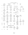
- Fig. 5 is a schematic illustrating an example of A13 message of Airbus.
- the A13 message mainly includes four parts of information, which respectively are a header, an APU history information, an operation parameter for starting the aircraft engine and an APU starting parameter.
- the header is composed of CC section and C1 section including mainly the following information: flight information of the aircraft, leg in which the message is generated, the state of the bleed air valve, total air temperature (i.e., external temperature) and like.
- the APU history information is composed of E1 section including the following information: the APU serial number, service hours and circulation and like.
- the operation parameter for starting the aircraft engine is composed of N1-S3 sections, wherein, N1 and S 1 indicate the operation status when the first aircraft engine is started, N2 and S2 indicate the operation status when the second aircraft engine is started, and N3 and S3 indicate the status after the APU starts all of engines successfully and when the aircraft is running slowly.
- the A 13 message includes a plurality of parameters relating to operation status of the APU.
- the operation parameter for starting the aircraft engine includes the EGT, the opening angle of the IGV, the inlet pressure of the compressor, the load compressor inlet temperature, the flow rate of the bleed air, the pressure of the bleed air, the oil temperature and the APU generator load.
- the parameter when the APU starts includes the starting time, the peak value of the EGT, the rotation speed at the peak value of EGT and the load compressor inlet temperature.
- the performance of the APU may relate to other parameters, in addition to the parameters in the A13 message.
- the amount of system data obtained by the aircraft can reach up to more than 13,000, wherein, a plurality of data can directly or indirectly reflect the performance of the APU. Therefore, it is one of issues to be solved by the present application that how to select suitable parameters from all of APU performance parameters and to generate a suitable algorithm corresponding to the selected parameters so as to accurately reflect the performance of the APU.
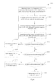
- Fig. 6 is a flow chart illustrating a method for detecting the performance of the APU according to one embodiment of the present application.
- the following operation information of the APU is obtained: EGT, LCIT (Compressor Inlet Temperature), STA (Starting Time), service time TSR and bleed air pressure PT.
- EGT EGT
- LCIT Compressor Inlet Temperature
- STA Startting Time
- TSR service time
- bleed air pressure PT i.e., bleed air pressure
- the difference between EGT and LCIT i.e., EGT-LCIT
- STA, TSR and PT are respectively compared with their respective threshold values.
- the respective threshold values are extreme values of respective parameters.
- each comparison result between EGT-LCIT, STA, TSR and PT and their respective threshold values is assigned with a weight.
- comparison results between EGT-LCIT, STA, TSR and PT and their respective threshold value considering the weight are integrated together.
- the integrated result does not exceed the second predetermined value, it is determined at step 6620 that the performance of the APU is normal, and at step 6710, it is determined whether the integrated result exceeds a third predetermined value. If the integrated result does not exceed the third predetermined value, it is determined at step 6720 that the performance of the APU is in the decline period. If the integrated result exceeds the third predetermined value, it is determined at step 6800 that the performance of the APU is in the fault period.
- the information required at step 6100 can be obtained from the APU message such as the A13 message.
- the A13 message of the operation status of the aircraft's APU can be obtained remotely from SITA (cios Internationale de Telecommunications Aéronautiques) network control center and ADCC (Aviation Data Communication Corporation) network control center in real time, and the obtained A13 message of the operation status of the aircraft's APU can be decoded by a message decoder so as to obtain the operation information of the aircraft's APU.
- the aircraft data system does not automatically generate the operation status message of the APU, corresponding sensor and trigger condition should be added to generate the desired APU message. If the existing APU message of the aircraft data system does not cover one or more of the EGT, LCIT, STA, TSR and PT, the generating condition of the APU message should be modified to add the lacking one or more parameters. Since the APU message can be transmitted to a data server of an airline in real time via ACARS or ATN, the real time monitoring of the performance of the APU can be achieved. Certainly, the transmission way of the message can avoid high cost and human error caused by the manual way.
- the information required at step 6100 can be obtained directly from the aircraft data system without generating the APU message.
- the threshold value for the difference of EGT and LCIT is EGT Redline .
- EGT Redline is an EGT redline value of the APU. EGT Redline depends on the model of the APU. Different models of APUs have different EGT redline values, which can be obtained from related manuals.
- the threshold value for STA is STA WarningLine which is a performance decline value of the STA and also depends on the model of the APU.
- the threshold value for TSR is TSR rt , which means a corresponding time where the reliability of time-on-wing of a certain model of APU is 70%.
- the threshold value of PT is PT Min , it is the minimum bleed air pressure required by a certain model of APU.
- the threshold value of PT also can be PT BaseLine , it is the lowest inherent amount of bleed air of a certain model of APU during normal operation. Comparison between EGT-LCIT, STA, TSR, PT and their respective threshold values can reflect an offset degree between current performance and standard performance of the APU, and further reflect a decline degree of the performance of the APU. EGT Redline , STA warningLine and PT Min or PT BaseLine can be obtained from related aircraft manuals or from manufactures. Certainly, they can be obtained through actual experiment. However, there is certain bias between TSR rt and a standard value in general, since TSR rt is influenced by geography and maintenance environments and other factors.
- the desired TSR rt can be obtained from actual data through utilizing Poisson distribution so as to obtain more accurate TSR rt .
- the parameters (such as a mean value) of Poisson distribution followed by the actual TSR can be calculated firstly, and then the corresponding TSR rt where the failure rate is 30% (the security rate is 70%) can be calculated utilizing the obtained parameters of Poisson distribution actually followed by the TSR.
- Comparison between EGT-LCIT, STA, TSR, PT and their respective threshold values can be done by calculating the ratio or difference. To facilitate considering weights of respective parameters, the ratios of EGT-LCIT, STA, TSR, PT and their respective threshold values are calculated at step 6200 according to one embodiment of the present application.
- EGT-LCIT, STA, TSR and PT have different influence on the performance of the APU, therefore, they need to be assigned with different weights.
- the TSR has the greatest influence, and thus R3 is generally greater than 0.25; EGT-LCIT and STA may have different effects regarding different models of APU; PT has relative small effects, and R4 is the lowest.
- PDI if PDI is less than 0.7, it means the performance of the APU is well; if the PDI is greater than 0.7 but less than 0.85, it means the performance of the APU is normal; and if the PDI is greater than 0.85, it means the performance of the APU is poor and in the decline period. If PDI is close to 1, for example PDI is greater than 0.95, it means the APU is in the failure period and failures may occur at any time. Therefore, an example of the first predetermined value at step 6510 is 0.7, an example of the second predetermined value at step 6610 is 0.85, and an example of the third predetermined value at step 6710 is 0.95.
- the APU message of the aircraft is obtained remotely from SITA network control center or ADCC network control center in real time, and the obtained APU message of the aircraft is decoded by an ACARS message decoder so as to obtain the operation information of the aircraft APU including: EGT:629, LCIT:33, STA:59, TSR:4883 and PT:3.66.
- PDI R ⁇ 1 ⁇ EGT - LCIT EGT Re ⁇ dLine + R ⁇ 2 ⁇ STA STA WarningLine + R ⁇ 3 ⁇ TSR TSR rt + R ⁇ 4 ⁇ PT Min PT
- EGT, LCIT, STA, TSR and PT are obtained in real time
- the PDI is obtained according to the formula (1), and then the obtained PDI is compared with the predetermined value, therefore, the method can accurately determine the performance of the APU based on the comparison between the PDI and the predetermined value.
- the ACARS message of operation status of the aircraft APU is obtained remotely in real time, which can reduce working load and enhance the work efficiency, compared with obtaining manually.
- the altitude and temperature can influence measuring results of the EGT and PT.
- the measured EGT and PT is converted into values under the standard condition and thus to remove the effect of altitude and temperature, so as to more accurately detect the performance of the APU.
- the altitude of 0 meter and the temperature of 50°C can be selected as the standard condition, and other altitude and temperature also can be e selected as the standard condition.
- PT cor PT ⁇ + ⁇ ⁇ PT
- PT cor the corrected bleed air pressure
- TAT is the ambient temperature
- a1, b1 and c1 are adjustment coefficient and can be measured through experiments.
- a1 has an order of 10 -5
- b1 has an order of 10 -2
- c1 is between 0 and -1.
- the measured PT can be converted into the corrected PT cor under the standard status according to formula (3).
- EGT cor EGT + ⁇ ⁇ EGT + p ⁇ 1 ⁇ PT ⁇ + p ⁇ 2 ⁇ PT cor - PT Re ⁇ q
- EGT cor EGT under the standard condition
- ⁇ EGT the function related to the temperature
- PT Req the lowest bleed air pressure required when the engine is started
- p1 and p2 are the adjustment coefficient.
- the range of values of the p1 is 20-60
- the range of value of the p2 is 70-100.
- the specific values of p1 and p2 can be obtained through experiments.
- different EGTs can be obtained under different altitudes, maintaining a certain power output and temperature of 50°C. Then, the measured EFTs are compared with the EGT under the temperature of 50°C and under sea level pressure, and the changes of the EGT and the temperature are regressed, so that the adjustment coefficient in the correction formula can be obtained.
- the corrected PDT if the corrected PDI is less than 0.7, it means the performance of the APU is well; if the corrected PDI is greater than 0.7 but less than 0.8, it means the performance of the APU is normal; if the corrected PDI is greater than 0.8, it means the performance of APU is poor and is in the decline period. And if PDI is greater than 0.85, it indicates that APU is in the failure period. Therefore, an example of the first predetermined value at step 6510 is 0.7, an example of the second predetermined value at step 6610 is 0.8, and an example of the third predetermined value at step 6710 is 0.85.
- Fig. 7 is a flow chart illustrating a method for detecting the performance of the APU according to another one embodiment of the present application.
- the method 700 for detecting the performance of the APU in the embodiment at step 710, one or more of the following operation information of the APU are obtained: EGT, STA, PT and the IGV angle.
- the method for obtaining operation information of the APU shown in fig. 6 can be applied in this embodiment.
- the EGT APU Exhaust Gas Temperature
- the EGT is an important parameter reflecting the performance of the APU. Since the EGT directly reflect the heat energy conversion efficiency of the whole APU when the APU operates at constant rotation speed. The lower the heat energy conversion efficiency of the APU is, the higher the value of the EGT is. Since the control system of the APU can control the fuel oil valve and the inlet angle of the IGV to ensure overheat will not occur, the PT and the angle of the IGV in the APU parameters can reflect change indicating the APU is close to overheat status and need to be prevented from overheating.
- the STA is a parameter reflecting the overall performance of the APU, which includes the performance of the starting motor, the performance of the gearbox, the efficiency of the compressor unit and power unit (i.e., one compressor and two stages of turbines).
- the current performance and changing trend of the APU can be reflected through monitoring the four key parameters EGT, IGV, STA and PT. Moreover, respectively monitoring the parameters also contributes to determine the failure sources and find hidden failures.
- step 720 it is determined whether one or more of EGT, IGV angle, STA and PT change significantly. It is determined that corresponding parameter deteriorates when one or more of EGT, IGV angle, STA and PT change significantly.
- EGT cor and PT cor mentioned in the above embodiment can replace the directly measured EGT and PT to remove the influence of the altitude and temperature so as to obtain more accurate results.
- X ⁇ ⁇ 0 + ⁇ ⁇ 1 ⁇ t 0
- X is any one of the EGT, STA, PT and IGV angle
- t 0 is the installation time
- ⁇ 0 ⁇ 1 are fitting parameters
- ⁇ 1 is the slope reflecting the changing trend of parameters.
- a plurality of values of one parameter of EGT, STA, PT and IGV obtained in a certain period are fitted so as to obtain ⁇ 1. ⁇ 1 is compared with the reference slope, and it is determined that said parameter of EGT, STA, PT and IGV changes significantly if there is significant difference between ⁇ 1 and the reference slope.
- the reference slope is calculated utilizing data of the APU having good operation condition. The data can be the data after initial installation of the same APU and also can be the data of other APU of the same model working well.
- a plurality of initial parameters recorded are averaged and thus respective initial value of every parameter is obtained as their respective reference values.
- the amount of recorded parameter is 10 or more.
- Variations can be obtained through comparison between the subsequent parameters and the reference value. These variations conform to the formula (8). Their slopes also can reflect the changing trend of parameters of the APU. Therefore, in this embodiment, comparing the slope of the variation of one of EGT, STA, PT and IGV relative to its corresponding reference value with the slope of the reference variation, it is determined that said one parameter among EGT, STA, PT and IGV changes significantly, i.e., said parameter deteriorates, if there is significant difference between two slopes.
- the values of one parameter of EGT, STA, PT and IGV in two consecutive periods of the same length are compared as independent samples. It is determined that said one parameter changes significantly and deteriorates if the above comparison shows significant difference.
- perform smooth processing to the values of parameters of measured EGT, STA, PT and IGV For reducing influence of fluctuation, perform smooth processing to the values of parameters of measured EGT, STA, PT and IGV According to one embodiment of the present application, perform smooth processing to the values of parameters through adopting multipoint smooth average rolling mean.
- the amount of multipoint is more than 3.
- step 730 it is determined whether the performance of the APU deteriorates through considering whether one or more of EGT, STA, PT and IGV change significantly.
- the performance of the APU deteriorates and the APU is in the decline period if any one of EGT, STA, PT and IGV deteriorates.
- it is determined that the performance of the APU deteriorates and the APU is in the decline period if both of EGT and PT deteriorate.
- the method shown in figs. 6 and 7 can be used simultaneously to more accurately detect the performance of the APU.
- Fig. 8 is a flow chart illustrating a method for detecting the performance of the APU according to further one embodiment of the present application.
- the method 800 for detecting the performance of the APU in the embodiment at step 810, one or two of EGT and PT of the operation information of the APU are obtained.
- the method for obtaining performance information of the APU mentioned above can be applied in this embodiment.
- the EGT and PT are compared with their respective limits.
- the EGT may be compared with the EGT RedLine
- the PT is compared with the PT Req which is the lowest bleed air pressure required when the engine starts.
- step 830 it is determined that any one of EGT and PT deteriorates if that one is close to its limit. According to one embodiment of the present application, it is determined that the performance of the APU is in decline period if any one of EGT and PT deteriorates. According to one embodiment of the present application, it is determined that the performance of the APU is in decline period if both of EGT and PT deteriorate.
- EGT Tolerance EGT Re ⁇ dLine - EGT cor
- EGT Tolerance is the margin of the EGT, i.e., the difference between the EGT and the EGT RedLine . Since the control system of the APU can prevent the EGT from overheating, it means that the APU cannot obtain more power by increasing fuel oil supply when the control system beginning to work. The power of the APU gradually decreases as service time passes, which means the APU is in the decline period. Therefore, it means the APU is in the decline period when the EGT Tolerance is close to 0.
- PT is an important parameter when the APU is in the decline period.
- the magnitude of the PT Tolerance reflects operation status of the APU in the decline period. When PT Tolerance is close to 0, the APU should be replaced.
- EGT and PT deteriorate and the APU is in the decline period and should be replaced.
- the method shown in figs. 6-8 can be used simultaneously to more accurately detect the performance of the APU.
- the method discussed in the embodiment can obtain EGT of the APU, LCIT, STA, TSR, PT and the angle of the IGV in real time, and thus perform detection of the performance of the APU through processing these parameters and determine whether the performance of the APU is in the decline period, which can support the maintenance of the APU for engineers and thus ensure normal operation of the APU so as to avoid delay and grounding of the aircraft. Meanwhile, targeted maintenance and operation control can be performed through evaluation of the performance of the APU, which will significantly reduce maintenance cost.
Landscapes
- Engineering & Computer Science (AREA)
- Combustion & Propulsion (AREA)
- Chemical & Material Sciences (AREA)
- Mechanical Engineering (AREA)
- General Engineering & Computer Science (AREA)
- Aviation & Aerospace Engineering (AREA)
- General Physics & Mathematics (AREA)
- Transportation (AREA)
- Manufacturing & Machinery (AREA)
- Physics & Mathematics (AREA)
- Testing And Monitoring For Control Systems (AREA)
- Control Of Positive-Displacement Air Blowers (AREA)
- Testing Of Devices, Machine Parts, Or Other Structures Thereof (AREA)
- Control Of Positive-Displacement Pumps (AREA)
- Separation By Low-Temperature Treatments (AREA)
- Air Conditioning Control Device (AREA)
- Fuel Cell (AREA)
Applications Claiming Priority (1)
| Application Number | Priority Date | Filing Date | Title |
|---|---|---|---|
| CN2011101889512A CN102343983A (zh) | 2011-07-07 | 2011-07-07 | 飞机apu性能检测方法 |
Publications (3)
| Publication Number | Publication Date |
|---|---|
| EP2543852A2 true EP2543852A2 (de) | 2013-01-09 |
| EP2543852A3 EP2543852A3 (de) | 2013-08-07 |
| EP2543852B1 EP2543852B1 (de) | 2015-10-21 |
Family
ID=45543127
Family Applications (1)
| Application Number | Title | Priority Date | Filing Date |
|---|---|---|---|
| EP12175299.2A Active EP2543852B1 (de) | 2011-07-07 | 2012-07-06 | Verfahren zur Bemessung der Leistung eines Hilfsgenerators |
Country Status (9)
| Country | Link |
|---|---|
| US (1) | US20130013222A1 (de) |
| EP (1) | EP2543852B1 (de) |
| JP (1) | JP5801771B2 (de) |
| KR (1) | KR101525285B1 (de) |
| CN (2) | CN102343983A (de) |
| AU (1) | AU2012204020B2 (de) |
| CA (1) | CA2782067C (de) |
| SG (1) | SG187331A1 (de) |
| TW (1) | TWI485088B (de) |
Cited By (4)
| Publication number | Priority date | Publication date | Assignee | Title |
|---|---|---|---|---|
| CN104512554A (zh) * | 2013-10-07 | 2015-04-15 | 通用电气航空系统有限公司 | 用于预测辅助动力单元故障的方法 |
| WO2015052458A1 (en) * | 2013-10-07 | 2015-04-16 | Ge Aviation Systems Limited | Method for diagnosing an auxiliary power unit fault |
| EP2829935A3 (de) * | 2013-07-24 | 2015-05-20 | Air China Limited | Verfahren und Vorrichtung zur Erkennung der Leistung einer APU-Brennstoffzelle |
| EP2829721A3 (de) * | 2013-07-24 | 2016-11-30 | Air China Limited | Verfahren und Vorrichtung zur Erkennung der Leistung eines APU-Anlassers |
Families Citing this family (27)
| Publication number | Priority date | Publication date | Assignee | Title |
|---|---|---|---|---|
| US8708554B2 (en) * | 2011-05-12 | 2014-04-29 | Arrowhead Products Corporation | Leak detection apparatus for aircraft bleed air systems |
| CN102331331A (zh) * | 2011-06-20 | 2012-01-25 | 中国国际航空股份有限公司 | 飞机机载氧气性能检测方法 |
| US9255664B2 (en) * | 2012-12-24 | 2016-02-09 | General Electric Company | Cryogenic fuel system with auxiliary power provided by boil-off gas |
| GB2514108B (en) * | 2013-05-13 | 2015-06-24 | Ge Aviat Systems Ltd | Method for diagnosing a bleed air system fault |
| CN104344946B (zh) * | 2013-07-24 | 2017-12-05 | 中国国际航空股份有限公司 | Apu涡轮叶片断裂与转轴卡阻故障的监控方法和装置 |
| CN104343476B (zh) | 2013-07-24 | 2016-06-08 | 中国国际航空股份有限公司 | 飞机辅助动力单元涡轮效率监控方法和装置 |
| CN104340368B (zh) * | 2013-07-24 | 2017-02-08 | 中国国际航空股份有限公司 | 飞机机翼防冰活门的监控系统和方法及其维修方法 |
| CN104340369B (zh) * | 2013-07-24 | 2017-03-08 | 中国国际航空股份有限公司 | 飞机辅助动力单元滑油冷却器性能监控方法及装置 |
| ES2773852T3 (es) * | 2013-12-27 | 2020-07-15 | Airbus Operations Sl | Una unidad auxiliar de potencia con un sistema de detección de incendios integrado |
| CN105021311B (zh) * | 2015-06-11 | 2017-08-25 | 北京空间飞行器总体设计部 | 一种在轨卫星推力器温度异常实时诊断方法 |
| CA3000595A1 (en) | 2015-09-30 | 2017-04-06 | Bombardier Inc. | Method of and system for presenting an operating status of an aircraft engine |
| FR3047274B1 (fr) * | 2016-01-29 | 2018-01-26 | Safran Power Units | Systeme de regulation electronique partiellement redondant |
| CN105910804B (zh) * | 2016-04-20 | 2018-05-01 | 中国商用飞机有限责任公司 | 用于监控飞机部附件的性能趋势的方法和装置 |
| US10823078B2 (en) | 2017-06-28 | 2020-11-03 | General Electric Company | Systems and methods for starting a turbine engine |
| CN107255973A (zh) * | 2017-07-07 | 2017-10-17 | 西安鹏泰航空动力技术有限公司 | 一种机翼表面温度测量与存储系统及测量存储控制方法 |
| US10951095B2 (en) | 2018-08-01 | 2021-03-16 | General Electric Company | Electric machine arc path protection |
| US11027719B2 (en) | 2018-12-03 | 2021-06-08 | General Electric Company | Distributed power generation for a vehicle system |
| CN109738195B (zh) * | 2018-12-28 | 2020-12-08 | 成都国营锦江机器厂 | Safir辅助动力装置起动试验模拟器及控制方法 |
| US11319883B2 (en) | 2019-02-20 | 2022-05-03 | Honeywell International Inc. | Auxiliary power unit power compressor health state diagnostic system and method |
| US11087567B2 (en) | 2019-05-21 | 2021-08-10 | Honeywell International S.R.O. | Systems and methods for auxiliary power unit health indicator computation |
| CN110718001B (zh) * | 2019-10-24 | 2021-07-06 | 哈尔滨工业大学 | 基于lstm和svr模型的飞机辅助动力装置的性能参数单步预测方法 |
| US12110121B2 (en) | 2020-03-05 | 2024-10-08 | Yaborã Indústria Aeronáutica S.A. | Systems and methods for defining APU steady state speed according to the aircraft operational conditions |
| CN111693180B (zh) * | 2020-05-27 | 2021-07-23 | 中国航空工业集团公司西安航空计算技术研究所 | 一种辅助动力系统排气温度超温故障检测方法 |
| CN113624505B (zh) * | 2021-08-24 | 2022-10-28 | 中国航发湖南动力机械研究所 | 一种压气机出口流场模拟装置 |
| CN115081517B (zh) * | 2022-06-06 | 2025-06-03 | 哈尔滨工业大学 | 一种基于扰动抑制的辅助动力装置性能退化特征提取方法 |
| CN115049236A (zh) * | 2022-06-06 | 2022-09-13 | 哈尔滨工业大学 | 一种多元特征融合分析的辅助动力装置健康状态估计方法 |
| CN116659881B (zh) * | 2023-06-01 | 2025-01-07 | 太仓点石航空动力有限公司 | 航空发动机的性能测试方法、装置、介质及电子设备 |
Family Cites Families (24)
| Publication number | Priority date | Publication date | Assignee | Title |
|---|---|---|---|---|
| GB1410526A (en) * | 1971-12-06 | 1975-10-15 | Westinghouse Electric Corp | Industrial gas turbine power plant having capability for effectuating automatic fuel transfer under load employing a digital computer |
| US4019315A (en) * | 1973-06-20 | 1977-04-26 | Westinghouse Electric Corporation | Gas turbine power plant control apparatus including a temperature reset starting control system and an ignition pressure control system |
| US4344142A (en) * | 1974-05-23 | 1982-08-10 | Federal-Mogul Corporation | Direct digital control of rubber molding presses |
| US4215412A (en) * | 1978-07-13 | 1980-07-29 | The Boeing Company | Real time performance monitoring of gas turbine engines |
| DE2948784A1 (de) * | 1979-03-08 | 1980-09-18 | Sundstrand Corp | Pruefsystem fuer eine dynamische maschine |
| US4788531A (en) * | 1983-11-17 | 1988-11-29 | The Boeing Company | Automatic fault reporting system |
| JPH05106922A (ja) * | 1991-10-18 | 1993-04-27 | Hitachi Ltd | 冷凍装置の制御方式 |
| US5222356A (en) * | 1991-12-12 | 1993-06-29 | Allied-Signal Inc. | Modulating surge prevention control for a variable geometry diffuser |
| US6009355A (en) * | 1997-01-28 | 1999-12-28 | American Calcar Inc. | Multimedia information and control system for automobiles |
| EP1332443A2 (de) * | 2000-09-11 | 2003-08-06 | Pinotage, LLC | System und verfahren zur gewinnung und benutzung von wartungsinformationen |
| US6466858B1 (en) * | 2000-11-02 | 2002-10-15 | General Electric Company | Methods and apparatus for monitoring gas turbine engine operation |
| US6625504B2 (en) * | 2001-03-22 | 2003-09-23 | Honeywell International Inc. | Auxiliary power unit engine monitoring system |
| KR100527702B1 (ko) * | 2002-09-26 | 2005-11-09 | 현대자동차주식회사 | 디젤엔진의 연료량 보상 장치 및 그 방법 |
| US6962043B2 (en) * | 2003-01-30 | 2005-11-08 | General Electric Company | Method and apparatus for monitoring the performance of a gas turbine system |
| US6880784B1 (en) * | 2003-05-08 | 2005-04-19 | Supersonic Aerospace International, Llc | Automatic takeoff thrust management system |
| US7367193B1 (en) * | 2003-07-23 | 2008-05-06 | Hamilton Sundstrand Corporation | Auxiliary power unit control method and system |
| US7487029B2 (en) * | 2004-05-21 | 2009-02-03 | Pratt & Whitney Canada | Method of monitoring gas turbine engine operation |
| US7769507B2 (en) * | 2004-08-26 | 2010-08-03 | United Technologies Corporation | System for gas turbine health monitoring data fusion |
| US7904282B2 (en) * | 2007-03-22 | 2011-03-08 | General Electric Company | Method and system for fault accommodation of machines |
| US20090048730A1 (en) * | 2007-08-17 | 2009-02-19 | General Electric Company | Method and system for planning repair of an engine |
| CN101858312B (zh) * | 2010-05-31 | 2012-02-08 | 重庆大学 | 风力发电机组实时运行状态评估系统及评估方法 |
| US20120117974A1 (en) * | 2010-11-16 | 2012-05-17 | Hamilton Sundstrand Corporation | Air flow delivery and fuel consumption control for aircraft air management and auxiliary power systems |
| CN102095572A (zh) * | 2010-12-06 | 2011-06-15 | 广州市熠芯节能服务有限公司 | 基于标杆产品比对的产品性能测试方法 |
| CN102320382A (zh) * | 2011-07-07 | 2012-01-18 | 中国国际航空股份有限公司 | 飞机性能检测方法 |
-
2011
- 2011-07-07 CN CN2011101889512A patent/CN102343983A/zh active Pending
-
2012
- 2012-07-05 CA CA2782067A patent/CA2782067C/en active Active
- 2012-07-06 JP JP2012152982A patent/JP5801771B2/ja active Active
- 2012-07-06 AU AU2012204020A patent/AU2012204020B2/en active Active
- 2012-07-06 SG SG2012050282A patent/SG187331A1/en unknown
- 2012-07-06 EP EP12175299.2A patent/EP2543852B1/de active Active
- 2012-07-06 US US13/543,486 patent/US20130013222A1/en not_active Abandoned
- 2012-07-06 TW TW101124337A patent/TWI485088B/zh active
- 2012-07-06 KR KR1020120074190A patent/KR101525285B1/ko active Active
- 2012-07-09 CN CN201210236612.1A patent/CN102866014B8/zh active Active
Non-Patent Citations (1)
| Title |
|---|
| None |
Cited By (10)
| Publication number | Priority date | Publication date | Assignee | Title |
|---|---|---|---|---|
| EP2829935A3 (de) * | 2013-07-24 | 2015-05-20 | Air China Limited | Verfahren und Vorrichtung zur Erkennung der Leistung einer APU-Brennstoffzelle |
| EP2829721A3 (de) * | 2013-07-24 | 2016-11-30 | Air China Limited | Verfahren und Vorrichtung zur Erkennung der Leistung eines APU-Anlassers |
| US9581124B2 (en) | 2013-07-24 | 2017-02-28 | Air China Limited | Method and apparatus for detecting performance of an APU starter |
| US9657649B2 (en) | 2013-07-24 | 2017-05-23 | Air China Limited | Method and apparatus for detecting performance of an APU fuel assembly |
| AU2014206178B2 (en) * | 2013-07-24 | 2018-01-25 | Air China Limited | Method and Apparatus for Detecting Performance of an APU Fuel Assembly |
| CN104512554A (zh) * | 2013-10-07 | 2015-04-15 | 通用电气航空系统有限公司 | 用于预测辅助动力单元故障的方法 |
| WO2015052458A1 (en) * | 2013-10-07 | 2015-04-16 | Ge Aviation Systems Limited | Method for diagnosing an auxiliary power unit fault |
| CN105593118A (zh) * | 2013-10-07 | 2016-05-18 | 通用电气航空系统有限公司 | 用于诊断出辅助功率单元故障的方法 |
| US10192368B2 (en) | 2013-10-07 | 2019-01-29 | Ge Aviation Systems Limited | Method for diagnosing an auxiliary power unit fault |
| CN105593118B (zh) * | 2013-10-07 | 2019-04-16 | 通用电气航空系统有限公司 | 用于诊断出辅助功率单元故障的方法 |
Also Published As
| Publication number | Publication date |
|---|---|
| JP2013019413A (ja) | 2013-01-31 |
| US20130013222A1 (en) | 2013-01-10 |
| CA2782067C (en) | 2014-12-02 |
| CA2782067A1 (en) | 2013-01-07 |
| AU2012204020A1 (en) | 2013-01-24 |
| SG187331A1 (en) | 2013-02-28 |
| AU2012204020B2 (en) | 2015-02-05 |
| CN102866014A (zh) | 2013-01-09 |
| TWI485088B (zh) | 2015-05-21 |
| KR20130006376A (ko) | 2013-01-16 |
| TW201307157A (zh) | 2013-02-16 |
| CN102866014B (zh) | 2016-02-10 |
| EP2543852A3 (de) | 2013-08-07 |
| KR101525285B1 (ko) | 2015-06-02 |
| CN102866014B8 (zh) | 2017-04-12 |
| JP5801771B2 (ja) | 2015-10-28 |
| EP2543852B1 (de) | 2015-10-21 |
| CN102343983A (zh) | 2012-02-08 |
Similar Documents
| Publication | Publication Date | Title |
|---|---|---|
| EP2543852B1 (de) | Verfahren zur Bemessung der Leistung eines Hilfsgenerators | |
| US8798848B2 (en) | Method for detecting whether performance of aircraft components is in the deterioration period | |
| US20180283278A1 (en) | Method and system for adjusting an operating parameter as a function of component health | |
| JP6205322B2 (ja) | 飛行機の補助動力ユニットの燃油ユニットの性能検出の方法と装置 | |
| EP2829686B1 (de) | Verfahren und Vorrichtung zur Überwachung der Turbinenleistung eines Flugzeughilfstriebwerks | |
| US10822112B2 (en) | Slope-based event detection for turbine engines | |
| HK1179691A (en) | Method for detecting the performance of auxiliary power unit | |
| HK1179691B (en) | Method for detecting the performance of auxiliary power unit | |
| US20250171155A1 (en) | Management of aircraft system components across different aircraft engines | |
| HK1179584B (en) | Method for detecting whether performance of aircraft component is in the deterioration period and method for maintenance of aircraft | |
| HK1202348B (en) | Method and apparatus for detecting performance of an apu fuel assembly | |
| HK1202330A1 (en) | Method and device for monitoring the malfunction of apu turbine vane fracture and rotor shaft jam | |
| HK1202330B (en) | Method and device for monitoring the malfunction of apu turbine vane fracture and rotor shaft jam |
Legal Events
| Date | Code | Title | Description |
|---|---|---|---|
| PUAI | Public reference made under article 153(3) epc to a published international application that has entered the european phase |
Free format text: ORIGINAL CODE: 0009012 |
|
| 17P | Request for examination filed |
Effective date: 20120706 |
|
| AK | Designated contracting states |
Kind code of ref document: A2 Designated state(s): AL AT BE BG CH CY CZ DE DK EE ES FI FR GB GR HR HU IE IS IT LI LT LU LV MC MK MT NL NO PL PT RO RS SE SI SK SM TR |
|
| AX | Request for extension of the european patent |
Extension state: BA ME |
|
| PUAL | Search report despatched |
Free format text: ORIGINAL CODE: 0009013 |
|
| AK | Designated contracting states |
Kind code of ref document: A3 Designated state(s): AL AT BE BG CH CY CZ DE DK EE ES FI FR GB GR HR HU IE IS IT LI LT LU LV MC MK MT NL NO PL PT RO RS SE SI SK SM TR |
|
| AX | Request for extension of the european patent |
Extension state: BA ME |
|
| RIC1 | Information provided on ipc code assigned before grant |
Ipc: F02C 7/32 20060101AFI20130701BHEP |
|
| RBV | Designated contracting states (corrected) |
Designated state(s): AL AT BE BG CH CY CZ DE DK EE ES FI FR GB GR HR HU IE IS IT LI LT LU LV MC MK MT NL NO PL PT RO RS SE SI SK SM TR |
|
| GRAP | Despatch of communication of intention to grant a patent |
Free format text: ORIGINAL CODE: EPIDOSNIGR1 |
|
| INTG | Intention to grant announced |
Effective date: 20150521 |
|
| GRAS | Grant fee paid |
Free format text: ORIGINAL CODE: EPIDOSNIGR3 |
|
| GRAA | (expected) grant |
Free format text: ORIGINAL CODE: 0009210 |
|
| AK | Designated contracting states |
Kind code of ref document: B1 Designated state(s): AL AT BE BG CH CY CZ DE DK EE ES FI FR GB GR HR HU IE IS IT LI LT LU LV MC MK MT NL NO PL PT RO RS SE SI SK SM TR |
|
| REG | Reference to a national code |
Ref country code: GB Ref legal event code: FG4D Ref country code: NL Ref legal event code: MP Effective date: 20151021 |
|
| REG | Reference to a national code |
Ref country code: CH Ref legal event code: EP |
|
| REG | Reference to a national code |
Ref country code: AT Ref legal event code: REF Ref document number: 756769 Country of ref document: AT Kind code of ref document: T Effective date: 20151115 |
|
| REG | Reference to a national code |
Ref country code: IE Ref legal event code: FG4D |
|
| REG | Reference to a national code |
Ref country code: DE Ref legal event code: R096 Ref document number: 602012011736 Country of ref document: DE |
|
| REG | Reference to a national code |
Ref country code: LT Ref legal event code: MG4D |
|
| REG | Reference to a national code |
Ref country code: AT Ref legal event code: MK05 Ref document number: 756769 Country of ref document: AT Kind code of ref document: T Effective date: 20151021 |
|
| REG | Reference to a national code |
Ref country code: FR Ref legal event code: PLFP Year of fee payment: 5 |
|
| PG25 | Lapsed in a contracting state [announced via postgrant information from national office to epo] |
Ref country code: IT Free format text: LAPSE BECAUSE OF FAILURE TO SUBMIT A TRANSLATION OF THE DESCRIPTION OR TO PAY THE FEE WITHIN THE PRESCRIBED TIME-LIMIT Effective date: 20151021 Ref country code: NO Free format text: LAPSE BECAUSE OF FAILURE TO SUBMIT A TRANSLATION OF THE DESCRIPTION OR TO PAY THE FEE WITHIN THE PRESCRIBED TIME-LIMIT Effective date: 20160121 Ref country code: LT Free format text: LAPSE BECAUSE OF FAILURE TO SUBMIT A TRANSLATION OF THE DESCRIPTION OR TO PAY THE FEE WITHIN THE PRESCRIBED TIME-LIMIT Effective date: 20151021 Ref country code: ES Free format text: LAPSE BECAUSE OF FAILURE TO SUBMIT A TRANSLATION OF THE DESCRIPTION OR TO PAY THE FEE WITHIN THE PRESCRIBED TIME-LIMIT Effective date: 20151021 Ref country code: NL Free format text: LAPSE BECAUSE OF FAILURE TO SUBMIT A TRANSLATION OF THE DESCRIPTION OR TO PAY THE FEE WITHIN THE PRESCRIBED TIME-LIMIT Effective date: 20151021 Ref country code: HR Free format text: LAPSE BECAUSE OF FAILURE TO SUBMIT A TRANSLATION OF THE DESCRIPTION OR TO PAY THE FEE WITHIN THE PRESCRIBED TIME-LIMIT Effective date: 20151021 Ref country code: IS Free format text: LAPSE BECAUSE OF FAILURE TO SUBMIT A TRANSLATION OF THE DESCRIPTION OR TO PAY THE FEE WITHIN THE PRESCRIBED TIME-LIMIT Effective date: 20160221 |
|
| PG25 | Lapsed in a contracting state [announced via postgrant information from national office to epo] |
Ref country code: RS Free format text: LAPSE BECAUSE OF FAILURE TO SUBMIT A TRANSLATION OF THE DESCRIPTION OR TO PAY THE FEE WITHIN THE PRESCRIBED TIME-LIMIT Effective date: 20151021 Ref country code: LV Free format text: LAPSE BECAUSE OF FAILURE TO SUBMIT A TRANSLATION OF THE DESCRIPTION OR TO PAY THE FEE WITHIN THE PRESCRIBED TIME-LIMIT Effective date: 20151021 Ref country code: FI Free format text: LAPSE BECAUSE OF FAILURE TO SUBMIT A TRANSLATION OF THE DESCRIPTION OR TO PAY THE FEE WITHIN THE PRESCRIBED TIME-LIMIT Effective date: 20151021 Ref country code: AT Free format text: LAPSE BECAUSE OF FAILURE TO SUBMIT A TRANSLATION OF THE DESCRIPTION OR TO PAY THE FEE WITHIN THE PRESCRIBED TIME-LIMIT Effective date: 20151021 Ref country code: SE Free format text: LAPSE BECAUSE OF FAILURE TO SUBMIT A TRANSLATION OF THE DESCRIPTION OR TO PAY THE FEE WITHIN THE PRESCRIBED TIME-LIMIT Effective date: 20151021 Ref country code: PT Free format text: LAPSE BECAUSE OF FAILURE TO SUBMIT A TRANSLATION OF THE DESCRIPTION OR TO PAY THE FEE WITHIN THE PRESCRIBED TIME-LIMIT Effective date: 20160222 Ref country code: PL Free format text: LAPSE BECAUSE OF FAILURE TO SUBMIT A TRANSLATION OF THE DESCRIPTION OR TO PAY THE FEE WITHIN THE PRESCRIBED TIME-LIMIT Effective date: 20151021 Ref country code: GR Free format text: LAPSE BECAUSE OF FAILURE TO SUBMIT A TRANSLATION OF THE DESCRIPTION OR TO PAY THE FEE WITHIN THE PRESCRIBED TIME-LIMIT Effective date: 20160122 |
|
| REG | Reference to a national code |
Ref country code: DE Ref legal event code: R097 Ref document number: 602012011736 Country of ref document: DE |
|
| PG25 | Lapsed in a contracting state [announced via postgrant information from national office to epo] |
Ref country code: CZ Free format text: LAPSE BECAUSE OF FAILURE TO SUBMIT A TRANSLATION OF THE DESCRIPTION OR TO PAY THE FEE WITHIN THE PRESCRIBED TIME-LIMIT Effective date: 20151021 |
|
| PLBE | No opposition filed within time limit |
Free format text: ORIGINAL CODE: 0009261 |
|
| STAA | Information on the status of an ep patent application or granted ep patent |
Free format text: STATUS: NO OPPOSITION FILED WITHIN TIME LIMIT |
|
| PG25 | Lapsed in a contracting state [announced via postgrant information from national office to epo] |
Ref country code: EE Free format text: LAPSE BECAUSE OF FAILURE TO SUBMIT A TRANSLATION OF THE DESCRIPTION OR TO PAY THE FEE WITHIN THE PRESCRIBED TIME-LIMIT Effective date: 20151021 Ref country code: DK Free format text: LAPSE BECAUSE OF FAILURE TO SUBMIT A TRANSLATION OF THE DESCRIPTION OR TO PAY THE FEE WITHIN THE PRESCRIBED TIME-LIMIT Effective date: 20151021 Ref country code: SK Free format text: LAPSE BECAUSE OF FAILURE TO SUBMIT A TRANSLATION OF THE DESCRIPTION OR TO PAY THE FEE WITHIN THE PRESCRIBED TIME-LIMIT Effective date: 20151021 Ref country code: SM Free format text: LAPSE BECAUSE OF FAILURE TO SUBMIT A TRANSLATION OF THE DESCRIPTION OR TO PAY THE FEE WITHIN THE PRESCRIBED TIME-LIMIT Effective date: 20151021 Ref country code: RO Free format text: LAPSE BECAUSE OF FAILURE TO SUBMIT A TRANSLATION OF THE DESCRIPTION OR TO PAY THE FEE WITHIN THE PRESCRIBED TIME-LIMIT Effective date: 20151021 |
|
| 26N | No opposition filed |
Effective date: 20160722 |
|
| PG25 | Lapsed in a contracting state [announced via postgrant information from national office to epo] |
Ref country code: SI Free format text: LAPSE BECAUSE OF FAILURE TO SUBMIT A TRANSLATION OF THE DESCRIPTION OR TO PAY THE FEE WITHIN THE PRESCRIBED TIME-LIMIT Effective date: 20151021 |
|
| PG25 | Lapsed in a contracting state [announced via postgrant information from national office to epo] |
Ref country code: BE Free format text: LAPSE BECAUSE OF FAILURE TO SUBMIT A TRANSLATION OF THE DESCRIPTION OR TO PAY THE FEE WITHIN THE PRESCRIBED TIME-LIMIT Effective date: 20151021 |
|
| REG | Reference to a national code |
Ref country code: CH Ref legal event code: PL |
|
| PG25 | Lapsed in a contracting state [announced via postgrant information from national office to epo] |
Ref country code: MC Free format text: LAPSE BECAUSE OF FAILURE TO SUBMIT A TRANSLATION OF THE DESCRIPTION OR TO PAY THE FEE WITHIN THE PRESCRIBED TIME-LIMIT Effective date: 20151021 |
|
| PG25 | Lapsed in a contracting state [announced via postgrant information from national office to epo] |
Ref country code: CH Free format text: LAPSE BECAUSE OF NON-PAYMENT OF DUE FEES Effective date: 20160731 Ref country code: LI Free format text: LAPSE BECAUSE OF NON-PAYMENT OF DUE FEES Effective date: 20160731 |
|
| REG | Reference to a national code |
Ref country code: IE Ref legal event code: MM4A |
|
| REG | Reference to a national code |
Ref country code: FR Ref legal event code: PLFP Year of fee payment: 6 |
|
| PG25 | Lapsed in a contracting state [announced via postgrant information from national office to epo] |
Ref country code: IE Free format text: LAPSE BECAUSE OF NON-PAYMENT OF DUE FEES Effective date: 20160706 |
|
| PG25 | Lapsed in a contracting state [announced via postgrant information from national office to epo] |
Ref country code: LU Free format text: LAPSE BECAUSE OF NON-PAYMENT OF DUE FEES Effective date: 20160706 |
|
| PG25 | Lapsed in a contracting state [announced via postgrant information from national office to epo] |
Ref country code: CY Free format text: LAPSE BECAUSE OF FAILURE TO SUBMIT A TRANSLATION OF THE DESCRIPTION OR TO PAY THE FEE WITHIN THE PRESCRIBED TIME-LIMIT Effective date: 20151021 Ref country code: HU Free format text: LAPSE BECAUSE OF FAILURE TO SUBMIT A TRANSLATION OF THE DESCRIPTION OR TO PAY THE FEE WITHIN THE PRESCRIBED TIME-LIMIT; INVALID AB INITIO Effective date: 20120706 |
|
| PG25 | Lapsed in a contracting state [announced via postgrant information from national office to epo] |
Ref country code: TR Free format text: LAPSE BECAUSE OF FAILURE TO SUBMIT A TRANSLATION OF THE DESCRIPTION OR TO PAY THE FEE WITHIN THE PRESCRIBED TIME-LIMIT Effective date: 20151021 Ref country code: MT Free format text: LAPSE BECAUSE OF NON-PAYMENT OF DUE FEES Effective date: 20160731 Ref country code: MK Free format text: LAPSE BECAUSE OF FAILURE TO SUBMIT A TRANSLATION OF THE DESCRIPTION OR TO PAY THE FEE WITHIN THE PRESCRIBED TIME-LIMIT Effective date: 20151021 |
|
| REG | Reference to a national code |
Ref country code: FR Ref legal event code: PLFP Year of fee payment: 7 |
|
| PG25 | Lapsed in a contracting state [announced via postgrant information from national office to epo] |
Ref country code: BG Free format text: LAPSE BECAUSE OF FAILURE TO SUBMIT A TRANSLATION OF THE DESCRIPTION OR TO PAY THE FEE WITHIN THE PRESCRIBED TIME-LIMIT Effective date: 20151021 |
|
| PG25 | Lapsed in a contracting state [announced via postgrant information from national office to epo] |
Ref country code: AL Free format text: LAPSE BECAUSE OF FAILURE TO SUBMIT A TRANSLATION OF THE DESCRIPTION OR TO PAY THE FEE WITHIN THE PRESCRIBED TIME-LIMIT Effective date: 20151021 |
|
| PGFP | Annual fee paid to national office [announced via postgrant information from national office to epo] |
Ref country code: DE Payment date: 20250724 Year of fee payment: 14 |
|
| PGFP | Annual fee paid to national office [announced via postgrant information from national office to epo] |
Ref country code: GB Payment date: 20250723 Year of fee payment: 14 |
|
| PGFP | Annual fee paid to national office [announced via postgrant information from national office to epo] |
Ref country code: FR Payment date: 20250728 Year of fee payment: 14 |