EP2543307B1 - Dishwasher, in particular domestic dishwasher, with at least one light-emitting passive illuminant in the interior - Google Patents
Dishwasher, in particular domestic dishwasher, with at least one light-emitting passive illuminant in the interior Download PDFInfo
- Publication number
- EP2543307B1 EP2543307B1 EP12173075.8A EP12173075A EP2543307B1 EP 2543307 B1 EP2543307 B1 EP 2543307B1 EP 12173075 A EP12173075 A EP 12173075A EP 2543307 B1 EP2543307 B1 EP 2543307B1
- Authority
- EP
- European Patent Office
- Prior art keywords
- dishwasher
- light
- passive
- door
- light source
- Prior art date
- Legal status (The legal status is an assumption and is not a legal conclusion. Google has not performed a legal analysis and makes no representation as to the accuracy of the status listed.)
- Active
Links
Images


Classifications
-
- A—HUMAN NECESSITIES
- A47—FURNITURE; DOMESTIC ARTICLES OR APPLIANCES; COFFEE MILLS; SPICE MILLS; SUCTION CLEANERS IN GENERAL
- A47L—DOMESTIC WASHING OR CLEANING; SUCTION CLEANERS IN GENERAL
- A47L15/00—Washing or rinsing machines for crockery or tableware
- A47L15/42—Details
- A47L15/4246—Details of the tub
-
- A—HUMAN NECESSITIES
- A47—FURNITURE; DOMESTIC ARTICLES OR APPLIANCES; COFFEE MILLS; SPICE MILLS; SUCTION CLEANERS IN GENERAL
- A47L—DOMESTIC WASHING OR CLEANING; SUCTION CLEANERS IN GENERAL
- A47L15/00—Washing or rinsing machines for crockery or tableware
- A47L15/42—Details
- A47L15/4251—Details of the casing
- A47L15/4257—Details of the loading door
-
- A—HUMAN NECESSITIES
- A47—FURNITURE; DOMESTIC ARTICLES OR APPLIANCES; COFFEE MILLS; SPICE MILLS; SUCTION CLEANERS IN GENERAL
- A47L—DOMESTIC WASHING OR CLEANING; SUCTION CLEANERS IN GENERAL
- A47L15/00—Washing or rinsing machines for crockery or tableware
- A47L15/42—Details
- A47L15/50—Racks ; Baskets
- A47L15/502—Cutlery baskets
Definitions
- the invention relates to a dishwasher, in particular domestic dishwasher, having a loading container having a loading opening, which can be closed by a door.
- Dishwashers are often equipped with lighting that illuminates, for example, the interior of the washing container with the door open, to facilitate the operation, for example, the loading or unloading of the receiving basket, or the recognition of certain functional parts, such as a handle on the receiving basket, by improved lighting conditions , or to improve the visual appearance of the dishwasher with the door open.
- a dishwashing machine which has a receiving device equipped with a lighting device.
- a light source is arranged outside the washing at a location not visible from the outside, the light is transmitted with the aid of a light guide in a arranged in the washing compartment further light guide, from which the light exits again.
- the light source is arranged outside the treatment room. If necessary, the light beams emitted by the light source can be deflected by at least one optical transmission means, such as a reflector and / or a diverging lens.
- the object of the invention is to propose a dishwasher, in particular a domestic dishwasher, in which an illumination and / or an optical design is achieved in an alternative manner.
- a dishwasher of the type mentioned in that in the interior of the dishwasher at least one as a result of illumination by at least one light source, in particular at least open Door, light-emitting, a photoluminescent substance containing passive illuminant is provided.
- a passive illuminant is to be understood to mean a luminous means which does not shine on its own power, such as an LED, but which spectrally changes the light of the light source interacting with it or also radiates it unchanged.
- Reflective material which reflects back light beams incident on it in a preferred direction, in particular in the direction of the light source, also counts in particular for the passive fluorescent lamp.
- the interior of the dishwasher preferably includes that area which is bounded or enclosed by the walls of the washing compartment and the door in its closed end position, including the walls of the washing compartment and the door facing this area.
- the interior of the dishwasher is in particular also still such zones attributable to the user is usually invisible when the door is closed when the dishwasher is used for a user and are visible only when partially and / or completely open the door.
- Such zones assigned to the interior of the dishwasher can be, for example, the upper-side outer edge or the upper edge and / or the two lateral outer edges or side walls of the door and / or an edge zone provided between the inner wall (inner door) and the outer wall (outer door) of the door Door in the positional level of the inner door, which in the final closing position of the door outside the wet area of the Rinse tank before and / or laterally attached to this door seal and comes into contact with this.
- a zone assigned to the interior of the dishwasher can be a depth-extending, inner-wall-side edge zone between the front edge of the washing container and a door seal attached to it on the inside, for example, at a predetermined distance away from the front edge of the washing container Side walls, the ceiling wall, and possibly the bottom wall of the washing compartment is attached.
- a reinforcing or frame element is mounted on the front and the front edge of the washing container at the front and front edges of the upper, front edge, and possibly at the front edge of the washing container.
- This can advantageously provide a sealing bed for the door seal.
- the zone associated with the interior of the dishwasher is formed by the inner wall-side edge zone region of the reinforcement or frame element between its front edge and the sealing bed with the door seal.
- the door seal portions frame a frontal feed opening of the washing container, behind which, viewed in the depth direction, the spray or wet area of the interior of the washing container lies.
- the one or more passive illuminants in the interior of the dishwashing machine are inside the interior of the washing container, in particular on one or more interior walls and / or on one or more inside the washing container accommodated, preferably movable components, and / or on the door, in particular inner wall of the Door, provided.
- surfaces of the inner walls of the washing container and / or functional components in the washing container such as e.g. one or more components of wash baskets such as e.g. Crockery or cutlery partially or completely brought to light and thus for a user of the dishwasher with the door open, especially in their approximately horizontal opening end, improved in a simple way made visible.
- one or more passive lighting means can also be provided outside the washing container in the interior of the dishwasher. This may, for example, a marginal zone of the inner wall of the door outside the wet area of the washing between the door seal of the washing in be the closing end position of the door coming into contact area and the outer edge of the inner wall of the door. Additionally or independently thereof, one edge zone of the washing container or of a frame member attached to the front side thereof, which is concealed in the approximately vertical closing end position of the door and runs around the door seal outside the wet region of the washing container, can be equipped with one or more passive lighting elements. As a result, the edge zone can be illuminated partially or continuously around the feed opening of the washing container.
- the one or more passive illuminants in the interior of the dishwasher make it possible in particular to also illuminate areas in the interior of the dishwasher, i. to visualize where an active light source is difficult or impossible to attach.
- movable functional components in the washing container such as e.g. rotatable spray arms, out and in movable receiving baskets, operating parts of feeders, and / or other handling components in a simple way to be made visible.
- an active light source such as e.g. LED or incandescent lamp required that this is laid by an electrical power supply unit, which is housed, for example, in the base support member below the washing compartment, a power line.
- the ambient light which falls on the respective passive illuminant when the door is open may already be sufficient to stimulate it to illuminate and / or focus, i. to reflect with a preferred direction.
- the passive lighting means can also be accommodated in the wet area of the washing container without the need for complex electrical insulation measures and / or spray-water protection measures, as in the case of an electric light source. Because the respective passive lighting means is formed in an advantageous manner largely insensitive to moisture and spray.
- At least one light source is provided as part of the dishwasher, which is arranged in particular in the interior of the dishwasher, preferably outside and / or inside the washing container and / or on the door, in particular inside wall of the door, and in whose light cone the respective passive lighting directly, or possibly also indirectly arranged or is positionable.
- the respective light source is arranged and aligned such that an interaction with the one or more passive lighting means in the interior of the dishwasher is effected.
- the dishwashing machine's own light source ensures that one or more passive illuminants having a high degree of freedom in the interior of the dishwasher, preferably on function components accommodated therein, can be attached and illuminated there by the light source in addition to the light source. Even in places with little space or at the door open from the outside difficult to reach places of the interior of the dishwasher, and / or on moving components such as receiving baskets so one or more passive lighting can be readily attached.
- the respective passive illuminant can be made to shine by virtue of the fact that this light beam directly or indirectly incident on it, which is emitted by the light source, in a targeted manner with a preferred direction, such as frontal forward, and reflected / or by this his material for emitting or for the emission of light is excited.
- At least one light source in the interior of the dishwasher is provided outside the wet area of the washing container at its front frame element, in particular at the upper portion of the front frame element, viewed in the depth direction of the dishwasher in front of the door seal of the door, and at least in its light cone a passive lighting in the interior of the dishwasher is arranged or positioned.
- a passive lighting in the interior of the dishwasher is arranged or positioned.
- At least one light source is present in the interior of the dishwasher, in the light cone of which at least one passive illuminant is arranged or positionable.
- no light-conducting cable between the respective light source and the respective passive lighting means is required, which extends both the range of applications and the possibilities for optical design in particular of the interior region of the dishwasher, which is also the inside of the door.
- movable components such as e.g.
- the light source in particular if it is part of the dishwasher, preferably its interior, a double function, for example, by serving to illuminate a dish rack and also at a remote location by means of their respective illuminated by her passive lighting can cause a luminous effect.
- the respective passive lighting means may expediently be either a separate part fixed to a component of the dishwasher or a component of the component, or may form it in its entirety.
- the respective passive lighting means is a variety of different options available.
- bulbs are used, the are formed reflective, such as due to a corresponding surface structure, or due to a coating, in particular with a reflective color unfold their lighting effect.
- passive illuminants are used whose luminous effect is based on the principle of photoluminescence.
- a corresponding substance here exemplified the known fluorescein, placed in an excited state, wherein in the case of fluorescence with virtually no time delay and in the phosphorescence with a time delay, for example, a few minutes, under Emission of fluorescent light returns to the ground state.
- the advantage of the passive luminescent means based on photoluminescence over reflective passive luminescent means is that with regard to the spatial design of the respective passive element, there is a greater latitude, since, for example, the dependence of the incidence and the angle of reflection of the light on reflective elements is largely irrelevant and therefore not to be considered.
- the photoluminescent substance can in principle have any state of aggregation, that is to say solid, liquid or gaseous.
- the passive illuminant may comprise a substance receiving container with a transparent wall.
- the passive illuminant may also be coated with a photoluminescent ink or other photoluminescent material layer.
- passive fluorescent lamps are preferably used which consist at least partially of a transparent, solid material containing the photoluminescent substance, in particular of a glass or plastic, for example acrylic glass.
- a transparent, solid material containing the photoluminescent substance in particular of a glass or plastic, for example acrylic glass.
- Such solids can be easily produced in almost any shape and are, which is especially true for plastic, easily deformed and machined.
- passive illuminants those which comprise or consist of a light guide which has at least one light entry surface are also still considered.
- the at least one light entry surface is expediently arranged or positionable so that it is illuminated by the light source.
- the light entry surface may optionally be preceded by a collecting optical element, or the light entry surface is itself part of such an element, which may for example have the shape of a parabolic mirror.
- a particularly advantageous embodiment provides that the light source and passive lighting means are arranged to be movable relative to each other.
- a passive illuminant can be arranged on a receiving basket, ie movable, and at least one light source can be arranged on a component, in particular stationary, and / or the door of the dishwasher.
- the door can also be considered as a stationary component, and that is when it is open.
- the light source is, for example, above the receiving basket, for example outside the wet space of the washing container at a position located above a receiving basket, for example at the upper edge of the washing container, in particular a front frame element mounted there before the sealing bed, which is a seal for liquid-tight closing of the door in its Sch formatdposition, arranged and - at least also - directed downwards, so that at least a portion of its cone of light detects the respective passive illuminant on the receiving basket in a height position below the light source, ie hits.
- one or more light sources on the underside of the upper portion of this frame or reinforcing element are provided in particular such that they are substantially invisible to a user standing in front of the dishwasher at the installation site, and thus do not dazzle the user in the on state.
- the passive illuminant attached to the receiving basket changes according to a further advantageous embodiment of the invention, its relative position to the light source. So that at least one region of the passive illuminant emits light in each depth position of the receiving basket, which can be displaced into different depth positions in the depth direction of the washing container, it expediently extends in the direction of movement of the receiving basket or in the depth direction of the dishwasher.
- the passive illuminant thus illuminates at different longitudinal sections.
- an illuminated area of the passive illuminant moves along the moving path of the receiving basket, such as when moving out front to back and when retracting the receiving basket in the reverse direction.
- the respective passive illuminant can in particular also be configured as an optical waveguide, ie it is designed such that the coupled or photoluminescent light is passed on within the passive illuminant, so that even areas which are not acted upon or illuminated directly by the light cone of the light source, at least to some extent shine.
- a passive illuminant embodied as a light guide or of a passive illuminant containing it
- light coupling during the retraction and extension movement of the receiving basket is ensured by having a light entry surface extending in the direction of movement or a plurality of light entry surfaces spaced apart in said direction, so that at different points or respectively In different depth positions of the receiving basket, which can be displaced in different depth positions in the depth direction of the washing container, light can be introduced into the passive lighting means.
- the passive illuminant is simultaneously a component or a functional part of the dishwasher or at least one - preferably functionally essential - element of such a part.
- a design is simple, e.g. with 2-component injection molding technology, feasible.
- this reduces the assembly effort that eliminates the need to fix a separate passive lighting element on a component of the dishwasher.
- Particularly advantageous is a measure of the type in question in functional elements of the receiving basket, in particular in a existing there, for holding items to be washed holding element, such as a hinged basket row or a serving for receiving cutlery insert a cutlery basket such. a cutlery drawer.
- the baskets for e.g. Crockery and / or cutlery form a central and functionally essential area of the dishwasher, which is subjected to a particularly critical consideration by the user.
- the categorization of cutlery and / or crockery is associated with a certain skill, so that supporting lightheads may be attached to one or more functional components of the cassettes, e.g. their holding elements or holding structures for receiving and holding crockery and / or cutlery for an improvement of the lighting conditions are advantageous.
- Another essential functional component is a spray arm present in the washing container. If a receiving basket located below the spray arm is loaded too high, the spray arm touches the wash ware or is prevented from rotating by it. Again, it makes sense if the spray arm is at least partially formed by a passive lighting or provided with a passive lighting to make him and his height position easily recognizable.
- the front-side hand or operating handles on the receiving baskets can each be provided with a passive lighting means to the respective user signal that the baskets can be pulled out of the rinsing container and pushed in.
- attachments preferably if they are made of plastic, in the receiving baskets, such as bearings for foldable folding prong rows or in different height positions and / or inclinations movable Etageren made recognizable.
- movable components in the interior of the dishwasher can be visually highlighted with the help of passive lighting in terms of their respective function, in particular mobility and / or variability, by lighting.
- the movable lid or flaps of a detergent and / or rinse aid addition which is mounted in the interior of the dishwasher, such as on the treatment room of the washing container facing inside of the door, each be provided with a passive lighting.
- the operating part of a salt addition device which is provided, for example, below the bottom of the washing container in a base support assembly of the dishwasher, can be expediently identified with a passive illuminant.
- Passive illuminants can therefore not only on a receiving basket, but generally at any point in the interior of the dishwasher, inside and outside the washing and / or on or in the door in any form, such as strip-shaped films or plates, for example on a wall , Preferably the bottom of the washing and / or at one of the loading opening bordering area, are arranged.
- the position of a light source cooperating with a passive light source is basically arbitrary, provided that its cone of light hits the passive illuminant.
- the respective light source is preferably part of the dishwasher, which is arranged in particular outside and / or inside the washing container, and / or on the door, preferably the inner wall of the door, and in whose light cone the respective passive lighting means is arranged or positionable. This ensures that the respective passive lighting means can be lit by a dishwashing machine-own light source, ie largely independent of the ambient light at the respective installation location of the dishwasher.
- the respective light source is outside the rinse container, i.
- the wet area of the washing container which is acted upon by the spraying system with cleaning liquid and is separated from the environment by the door-cooperating door seal, is arranged outside of the environment.
- the light source can be arranged at the upper edge, in particular above the upper edge of the washing container.
- at least one light source in the interior of the dishwasher can be arranged outside the wet area of the washing container on its front frame element, in particular on the upper portion of this front frame element (in front view) in front of a seal provided for the door, which is held in a sealing bed of the frame element.
- At least one light source within the washing container may be fixed to a wall of the washing container, for example on a side or rear wall. Additionally or independently thereof, at least one light source may possibly also be arranged on the inside of the door (facing the interior of the washing compartment in the closing end position of the door).
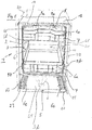
- Fig. 1 and 2 each show a household dishwasher 1, which comprises a front loading opening 2 having a washing container 3.
- the rinsing container 3 may be partially or completely surrounded by an outer housing and / or other attachments in the region of its walls.
- an outer housing KO additionally indicated by dash-dotted lines.
- a spraying device for example in the form of one or more spray arms 4 (FIG. Fig. 4 ) arranged.
- the loading opening 2 can be closed by a door 5 hinged to the front of the dishwasher.
- the rinse tank 3 has to offset its front edge in the depth direction into the interior of the washing container offset a strip or line-shaped seal DB in a sealing bed on its two side walls 10, its top wall 14, and possibly bottom wall 11. The spanned by the seal DB, thought
- Laying plane thus defines the loading opening 2 of the washing container 3, which is closed by the inner wall 51 of the door in its approximately vertical final closing position.
- the area between the seal DB provided for the liquid-tight closure of the door and the front edge of the washing container 3 (viewed in the depth direction) lies outside the wet area of the washing container and is suitable for accommodating one or more light sources such as e.g. LEDs and / or passive lighting advantageous available.
- At least one light source is accommodated in the closing end position of the door in the interior of the dishwasher and is arranged or positionable outside the wet area of the washing compartment.
- one or more light sources on a front frame element such.
- DB and thus outside the wet area of the interior of the washing container are arranged or positioned so that the respective passive light source in the interior of the dishwasher for emitting light is stimulated or stimulated in the light cone of the respective light source and / or incident light rays are reflected in a preferred direction to the front ,
- the respective passive illuminant may e.g.
- the one or more light sources e.g. LEDs in the largely dry area before the sealing bed DB with the door seal of the washing container, the light sources are also largely electrically safe housed inside the dishwasher.
- one or more light sources 9a are attached to the upper portion of the frame element RE of the washing container 3 and their respective light cone is directed substantially from top to bottom.
- a passive lighting means 6a which is provided on the front side such as on a front handle and / or inside the respective receiving basket 7 such as an upper basket or lower basket, in a plane below the light source (s) 9a, ie is arranged in a lower height position relative to the light source or sources 9a, and from the washing container 3 is partially or completely moved out, be brought to a user for illuminating or lighting.
- the parking position for a lower basket 7 on the inner wall surface 51 of the door 5 can be made recognizable to a user and animated to extend the lower basket 7 for loading or unloading on the inner wall surface 51 of the door 5 in its approximately horizontal ⁇ Stammsendposition.
- the one or more light sources 9a are attached to the underside of the upper portion of the frontally projecting frame element RE of the washing container 3, for a user standing in front of the dishwasher, a largely low-glare or glare-free illumination of the area below the one or more light sources 9a ensured become.
- passive lighting means are provided, which, as will be explained below, at various points, for example on an inner wall such as side wall 10 and / or bottom wall 11 of the washing compartment 2, the door 5 , and / or at least one in the depth direction, preferably horizontally extendable and retractable receiving basket 7, in particular dish rack and / or a retractable and extendable cutlery drawer or the like, etc. may be arranged.
- the passive illuminants are each positioned so that they are acted upon by the light cone such as 8 at least one light source such as 9a or by the light emitted by the light source.
- the respective light source may preferably be arranged within the washing container 2, wherein the side walls 10, the rear wall 13 and / or the top wall 14 come into question.
- a passive illuminant it is also possible to use the light of a light source arranged outside the dishwasher, for example the light of a kitchen lamp or daylight.
- the following description refers primarily to the embodiment with arranged within the dishwasher light source, but with comments on Design and arrangement of passive lighting mutatis mutandis also apply to the embodiment with external light source.
- Passive illuminants in addition to reflective elements or elements which are coated in a reflective manner, include passive illuminants which contain a photoluminescent substance. It is conceivable that such a substance is applied to a surface area of the washing container 2, the door 5 and / or a component such as a receiving basket 7. Another possibility is that the passive illuminant is at least partially formed of a translucent solid such as glass, plastic or a composite of said materials. Such passive lighting or, above all, such plastics are known, so that no further explanation is needed.
- the one or more passive lighting means can not only be attached as a separate part to a component, for example a spray arm 4 or a receiving basket 7, but form a part of the component or component as a whole.
- a component for example a spray arm 4 or a receiving basket 7, but form a part of the component or component as a whole.
- spraying arm 4 shown in the form of strips may be mounted as passive lighting means 6j. It is also conceivable, however, that the entire spray arm 4 or at least a part thereof is formed from a passive illuminant, for example a photoluminescent plastic.
- optical fibers come into question, that is to say elements made of plastic, which are designed in such a way that light of the light source, such as 9a, entering via a light entry surface 16 (see FIG FIG. 4 ) is forwarded by total reflection within the passive illuminant, so that it exits again at a light exit surface 17 remote from the light entry surface 16 or also at other surfaces extending, for example, in the propagation direction of the light.
- LISA plastics - light-collecting plastics - can be used.
- plastics contain a fluorescent dye, but they are dimensioned so that the fluorescent light is forwarded by total reflection, but in addition a certain part of the fluorescent light exits on all surfaces of the passive illuminant, such as 6e, which extend along the propagation direction of the light.
- the dishwashing machine 1 here comprises an upper and a lower dish rack 7.
- the front area thereof is provided with a passive lighting means 6a positioned at its upper edge and designed in the form of a strip extending essentially in the width direction of the washing compartment.
- the passively luminous band on the respective dish rack preferably runs substantially parallel to a plane extending in the height and width direction of the washing compartment. It can act as a front panel or front panel for the respective crockery basket.
- a partial section, in particular the middle region of the frontal section of the strap can be designed as a handle, preferably a grip recess.
- Light sources 9a can also be used to illuminate the interior of the washing container 2. They are generally designed so that they form a downward and obliquely inward (into the interior 31 of the washing container 3) directed light cone 8 (indicated by the arrows 19 in Fig. 4 ). In this way it is ensured that when retracted receiving basket 7, as in Fig.
- both front-side passive lighting means 6a of the receiving baskets 7 are exposed to light and excited to shine.
- light sources such as 9b, 9d may additionally or independently of the upper-side light sources 9a also be positioned at other locations, for example at a point from which the receiving baskets 7 can be illuminated from the side.
- the light source 9b can be arranged inside or outside the washing container 2 and at one of its side walls 10 or at a lateral position of the dishwasher machine body.
- the light source 9b, and possibly also the light sources 9a positioned above the upper receiving basket 7, can be aligned such that they also apply light to areas of the door, for example lateral areas 20, so that passive light means 6b, 6c arranged there, for example likewise strip-shaped, adjoin the light Lights are excited.
- the passive lighting means 6c are with the door closed 5 within the washing compartment 2 or in the wet area of the Dishwasher 1 is arranged, that is, in the area which is acted upon by the closed door of a present in the washing 3 spray system, for example, the above-mentioned spray arm 4.
- the passive lighting means 6b are arranged outside the wet area, ie they are located with the door closed to the right or left outside of a present on the inside of the door 5 sealing area 23, at which with the door closed, the door seal DB, in the FIG. 1 only schematically indicated, is present.
- a single strip-shaped passive illuminant such as only 6b or only 6c per side area of the door may be sufficient for lighting.
- the lateral passive lighting means such as 6b, 6c, extend on the inner wall of the door substantially along their entire extent in the depth direction of the washing compartment. This corresponds in the vertical closing position of the door about its height extension.
- Passive Illuminants 6l and / or 6m, the z. B. in strip form in the depth direction of the washing container 3, may be provided.
- These passive illuminants 6l, 6m can also be illuminated by means of the light source (s) 9a, 9b.
- Such further passive lighting means 6l on the side walls 10 of the washing container are in the FIG. 1 indicated by dash-dotted lines.
- the passive illuminants 6m at the bottom 11 of the washing compartment are in the FIG. 2 also shown in dash-dotted lines.
- a light source 9d is additionally shown in dash-dot lines in the inner door 51. It is arranged approximately centrally with respect to the width of the door. It emits a cone of light 8 in the direction of the passive illuminant 6a on the front side of the two stacked baskets 7 arranged one above the other.
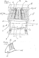
- Fig. 2 shows an example of a passive lighting means 6d, which serves as a functional element for a basket designed as a cutlery drawer or a cutlery basket 7 'basket above the one or more dishes basket or baskets such as 7.
- the passive lighting means 6d forms a light-conducting receiving strip 24 for cutlery.
- two such receiving strips 24 in the width direction of the dishwasher 1 are arranged so that they are acted upon by the light cone 8 of above the cutlery basket 7 'arranged two light sources 9a.
- the upper-side light entry surface 16 (see FIG. 4 ) of the respective receiving bar 24 thus moves with the sliding movement of the cutlery drawer 7 '.
- the respective receiving strip 24 preferably extends along the depth extent of the cutlery drawer 7 '. Depending on the depth position of the cutlery drawer 7 ', another area of the receiving strips 24 illuminates.
- the receiving strips 24, which preferably extend over the entire depth of the cutlery drawer 7', are, for example, as in FIG Fig. 2a designed. They comprise a strip-shaped base part 25, on which upwardly extending holding elements 27 are formed in a row, which release between each serving for the insertion of cutlery interstices 26.
- the receiving strip 24 or the passive illuminant 6d is either formed as a separate part, which is fixed to the cutlery drawer or on the cutlery basket 7 ', or it is an integral component of the cutlery basket 7', for example molded on this.
- the passive illuminant 6d can act not only light-conducting, but additionally or independently thereof in particular luminescent.
- the passive illuminant 6d embodied as a receiving strip 24 or else a differently designed passive illuminant is embodied as an optical waveguide it can be particularly expedient if a light source 9c is preferably attached to the rear wall 13 of the rinsing container 3 (FIG. Fig. 5 ) is arranged.
- the respective light source 9 c is located at a height level, which is about the height level of the trajectory of their respective assigned receiving basket 7, in particular at their respective assigned cutlery drawer 7 ', existing passive lighting means, such as a receiving bar 24 of the type described above, located.
- This embodiment ensures that the passive illuminant in each depth position of the respective receiving basket 7, 7 'is acted upon by the light cone 8 of the rear light source 9c, so that light can be coupled from the rear to the front.
- the end face of the passive illuminant 6d facing the rear wall 13 can serve as a light coupling surface 16.
- a light coupling element 28 comprising a light entry surface to be arranged at the rear end of the passive illuminant 6d.
- the light coupling element 28 is, for example, an element designed in the manner of a parabolic mirror, the mirror surface of which Light entrance surface 16 forms.
- the beam path of a light beam is in Fig. 5 indicated by the arrow 29.
- a passive illuminant 6e is shown that, for example, similar to the receiving strip 24 described above can be configured and arranged on the respective receiving basket, but it is a luminescent, in particular fluorescent effective passive lighting.
- a receiving basket 7 or 7 ' is moved out of the washing container 3 and back into it, a region 30 of the light source 9a facing the light source 9a of the passive illuminating means 6e is acted upon by the light cone 8 and thereby illuminated.
- the passive illuminant 6a is designed so that it is responsible for the resulting luminescence radiation, which in Fig.
- FIG. 3 shows a receiving basket 7, the side guide rollers 35 has. These guide rollers 35, optionally also holding them, for example, in the form of a extending in the depth direction of the receiving basket 7 strip carrier 36 may be provided with a passive lighting means or even form such a passive lighting means 6f and 6g.
- a centrally arranged plate 37 which forms a bottom region of the receiving basket 7, of a luminescent plastic can be attached to the receiving basket 7, for example. The plate is pulled upwards at its front end, forming a visible light exit surface 17 when the door is open.
- the side edges 38 of the plate 37 can serve, in which case a gap 40 located between the lateral edge 38 and a basket wire 39 extending in the depth direction of the receiving basket 7 can be illuminated.
- the passive illuminant 6h formed as a plate 37 may have a light entry surface 16, wherein in the present case of a at the rear end of the plate 37 upwardly projecting leg 43 and that is arranged on the rear side 13 of the washing container 3 side facing.
- the plate 37 is penetrated by a central opening 41, wherein the opening 41 delimiting edges 42 of the plate 37 also serve as light exit surfaces 17.
- a further basket element which is designed as passive illuminant 6i or comprises such a luminous means.
- This is a row of basket stiles 44 extending in the depth direction of the receiving basket 7 and projecting upwards from, for example, a wire-shaped base support 45 extending in the depth direction of the receiving basket 7.
- the individual Korbstacheln 44 and the base support 45 are formed by a light guide of the type described above or contain a light guide, wherein at the free ends of the Korbstacheln 44 light exit surfaces 17 are arranged.
- a further passive lighting means 6k is shown, which is arranged on the rear side of the receiving basket 7, for example in its bottom area, and is, for example, a strip of material extending over the entire width of the receiving basket 7.
- the irradiation of light can, for example, via a arranged on the rear wall 13 of the washing container 3 light source 9c ( Fig. 5 ) respectively.
- a light entry surface (not shown) may be present, via which, for example, light from the light source 9c can be coupled in.
- a passive light element 6l is finally still Fig. 4 refer to. It is arranged on an inner wall, such as the respective side wall 10 of the washing container 3, and configured, for example, as a strip or strip extending in the depth direction.
Description
Die Erfindung betrifft eine Geschirrspülmaschine, insbesondere Haushaltsgeschirrspülmaschine, mit einem eine Beladeöffnung aufweisenden, von einer Tür verschließbaren Spülbehälter. Geschirrspülmaschinen werden vielfach mit einer Beleuchtung ausgestattet, welche bei geöffneter Tür beispielsweise den Innenraum des Spülbehälters ausleuchtet, um die Bedienung, beispielsweise das Be- oder Entladen des Aufnahmekorbs, oder das Erkennen bestimmter Funktionsteile, wie etwa einen Handgriff am Aufnahmekorb, durch verbesserte Lichtverhältnisse zu erleichtern, oder das optische Erscheinungsbild der Geschirrspülmaschine bei geöffneter Tür zu verbessern.The invention relates to a dishwasher, in particular domestic dishwasher, having a loading container having a loading opening, which can be closed by a door. Dishwashers are often equipped with lighting that illuminates, for example, the interior of the washing container with the door open, to facilitate the operation, for example, the loading or unloading of the receiving basket, or the recognition of certain functional parts, such as a handle on the receiving basket, by improved lighting conditions , or to improve the visual appearance of the dishwasher with the door open.
Z.B. aus der
Aufgabe der Erfindung ist es eine Geschirrspülmaschine, insbesondere eine Haushaltsgeschirrspülmaschine vorzuschlagen, bei der eine Beleuchtung und/oder eine optische Gestaltung auf eine alternative Art und Weise erreicht ist/sind.The object of the invention is to propose a dishwasher, in particular a domestic dishwasher, in which an illumination and / or an optical design is achieved in an alternative manner.
Diese Aufgabe wird bei einer Geschirrspülmaschine der eingangs genannten Art dadurch gelöst, dass im Innenraum der Geschirrspülmaschine wenigstens ein infolge einer Beleuchtung durch mindestens eine Lichtquelle, insbesondere zumindest bei geöffneter Tür, Licht abstrahlendes, eine photolumineszierende Substanz enthaltendes Passivleuchtmittel vorgesehen ist.This object is achieved in a dishwasher of the type mentioned in that in the interior of the dishwasher at least one as a result of illumination by at least one light source, in particular at least open Door, light-emitting, a photoluminescent substance containing passive illuminant is provided.
Unter einem Passivleuchtmittel ist dabei ein Leuchtmittel zu verstehen, das nicht aus eigener Kraft leuchtet, wie etwa eine LED, sondern welches das Licht der mit ihm zusammenwirkenden Lichtquelle spektral verändert oder auch unverändert wieder abstrahlt. Zum Passivleuchtleuchtmittel zählt insbesondere auch Reflektormaterial, das auf ihn auftreffende Lichtstrahlen in eine Vorzugsrichtung, insbesondere in Richtung der Lichtquelle, zurückreflektiert.A passive illuminant is to be understood to mean a luminous means which does not shine on its own power, such as an LED, but which spectrally changes the light of the light source interacting with it or also radiates it unchanged. Reflective material, which reflects back light beams incident on it in a preferred direction, in particular in the direction of the light source, also counts in particular for the passive fluorescent lamp.
Diese Effekte können bereits durch eine Raumbeleuchtung oder durch Tageslicht, also eine externe Beleuchtung, hervorgerufen werden, sobald die Tür der Geschirrspülmaschine geöffnet wird. Somit kann bei entsprechender Anordnung eines oder mehrerer zusätzlicher Passivleuchtmittel im Innenraum der Geschirrspülmaschine die Sichtbarkeit von ein oder mehreren Funktionsbauteilen wie z.B. Aufnahmekörben für Spülgut oder Besteck, und/oder von Bauteilen für die Bedienung relevanter Teile wie z.B. Griffe an den Aufnahmekörben und/oder von Elementen von Zugabeeinrichtungen für Reinigungsmittel, Klarspülmittel, Salz, und/oder sonstigen Zusatzstoffen, welche beispielsweise auf der Innenwandung der Tür oder am Boden des Spülbehälters vorgesehen sind, in einfacher Weise verbessert werden.These effects can already be caused by a room lighting or by daylight, so an external lighting, as soon as the door of the dishwasher is opened. Thus, with appropriate arrangement of one or more additional passive lighting means in the interior of the dishwasher, the visibility of one or more functional components, such as e.g. Storage baskets for items to be washed or cutlery, and / or components for the operation of relevant parts, such as e.g. Handles on the receiving baskets and / or elements of adding devices for cleaning agents, rinse aid, salt, and / or other additives, which are provided for example on the inner wall of the door or at the bottom of the washing, can be easily improved.
Im Rahmen der Erfindung zählt dabei zum Innenraum der Geschirrspülmaschine vorzugsweise derjenige Raumbereich, der von den Wandungen des Spülbehälters und der Tür in deren Schließendstellung betrachtet begrenzt bzw. eingeschlossen wird, einschließlich der diesem Raumbereich zugewandten Wandungen des Spülbehälters und der Tür. Dem Innenraum der Geschirrspülmaschine sind insbesondere auch noch solche Zonen zuzurechnen, die bei verschlossener Tür bei gebrauchsüblicher Aufstellung der Geschirrspülmaschine für einen Benutzer normalerweise unsichtbar sind und erst beim teilweisen und/oder vollständigen Öffnen der Tür sichtbar werden. Solche, dem Innenraum der Geschirrspülmaschine zugeordnete Zonen können z.B. der oberseitige Außenrand bzw. die Oberkante und/oder die beiden seitlichen Außenränder bzw. Seitenwangen der Tür und/oder eine zwischen der Innenwandung (Innentür) und der Außenwandung (Außentür) der Tür vorgesehene Randzone der Tür in der Lageebene der Innentür sein, die in der Schließendposition der Tür außerhalb des Nassbereichs des Spülbehälters vor und/oder seitlich einer an diesem angebrachten Türdichtung liegt und mit dieser in Kontakt kommt. Korrespondierend hierzu kann eine dem Innenraum der Geschirrspülmaschine zugeordnete Zone eine sich in Tiefenrichtung erstreckende, innenwandseitige Randzone zwischen der Vorderkante des Spülbehälters und einer an ihm z.B. innenseitig angebrachten Türdichtung sein, die in einer vorgegebenen Distanz von der Vorderkante des Spülbehälters weg in die Tiefe versetzt an den Seitenwänden, der Deckenwand, und ggf. der Bodenwand des Spülbehälters angebracht ist.In the context of the invention, the interior of the dishwasher preferably includes that area which is bounded or enclosed by the walls of the washing compartment and the door in its closed end position, including the walls of the washing compartment and the door facing this area. The interior of the dishwasher is in particular also still such zones attributable to the user is usually invisible when the door is closed when the dishwasher is used for a user and are visible only when partially and / or completely open the door. Such zones assigned to the interior of the dishwasher can be, for example, the upper-side outer edge or the upper edge and / or the two lateral outer edges or side walls of the door and / or an edge zone provided between the inner wall (inner door) and the outer wall (outer door) of the door Door in the positional level of the inner door, which in the final closing position of the door outside the wet area of the Rinse tank before and / or laterally attached to this door seal and comes into contact with this. Corresponding to this, a zone assigned to the interior of the dishwasher can be a depth-extending, inner-wall-side edge zone between the front edge of the washing container and a door seal attached to it on the inside, for example, at a predetermined distance away from the front edge of the washing container Side walls, the ceiling wall, and possibly the bottom wall of the washing compartment is attached.
Zweckmäßig kann es insbesondere sein, wenn ein Verstärkungs- oder Rahmenelement am oberen, vorderen Rand, den beiden seitlichen, vorderen Rändern, und ggf. am unteren, vorderen Rand des Spülbehälters frontseitig montiert ist und nach vorne absteht. Dieses kann vorteilhafterweise ein Dichtbett für die Türdichtung bereitstellen. Dann ist die dem Innenraum der Geschirrspülmaschine zugeordnete Zone durch den innenwandseitigen Randzonenbereich des Verstärkungs- oder Rahmenelements zwischen dessen Vorderkante und dem Dichtbett mit der Türdichtung gebildet.
Auf diese Weise umrahmen die Türdichtungsabschnitte eine frontale Beschickungsöffnung des Spülbehälters, hinter der in Tiefenrichtung betrachtet der Sprüh- bzw. Nassbereich des Innenraums des Spülbehälters liegt.It may be expedient, in particular, if a reinforcing or frame element is mounted on the front and the front edge of the washing container at the front and front edges of the upper, front edge, and possibly at the front edge of the washing container. This can advantageously provide a sealing bed for the door seal. Then, the zone associated with the interior of the dishwasher is formed by the inner wall-side edge zone region of the reinforcement or frame element between its front edge and the sealing bed with the door seal.
In this way, the door seal portions frame a frontal feed opening of the washing container, behind which, viewed in the depth direction, the spray or wet area of the interior of the washing container lies.
Zweckmäßigerweise sind die ein oder mehreren Passivleuchtmittel im Innenraum der Geschirrspülmaschine innerhalb des Innenraums des Spülbehälters, insbesondere an ein oder mehreren Innenwänden und/oder an ein oder mehreren im Innenraum des Spülbehälters untergebrachten, bevorzugt beweglichen Komponenten, und/oder an der Tür, insbesondere Innenwandung der Tür, vorgesehen. Dadurch können Flächen der Innenwände des Spülbehälters und/oder Funktionsbauteile im Spülbehälter wie z.B. ein oder mehrere Komponenten von Aufnahmekörben für Spülgut wie z.B. Geschirr oder Besteck teilweise oder ganz zum Leuchten gebracht und somit für einen Benutzer der Geschirrspülmaschine bei geöffneter Tür, insbesondere in deren etwa waagerechter Öffnungsendstellung, in einfacher Weise verbessert sichtbar gemacht werden.Expediently, the one or more passive illuminants in the interior of the dishwashing machine are inside the interior of the washing container, in particular on one or more interior walls and / or on one or more inside the washing container accommodated, preferably movable components, and / or on the door, in particular inner wall of the Door, provided. As a result, surfaces of the inner walls of the washing container and / or functional components in the washing container, such as e.g. one or more components of wash baskets such as e.g. Crockery or cutlery partially or completely brought to light and thus for a user of the dishwasher with the door open, especially in their approximately horizontal opening end, improved in a simple way made visible.
Zusätzlich oder unabhängig hiervon können ein oder mehrere Passivleuchtmittel auch außerhalb des Spülbehälters im Innenraum der Geschirrspülmaschine vorgesehen sein. Dies kann beispielsweise eine Randzone der Innenwandung der Tür außerhalb des Nassbereichs des Spülbehälters zwischen dem mit der Türdichtung des Spülbehälters in der Schließendstellung der Tür in Kontakt kommenden Aufsetzbereich und der Außenkante der Innenwandung der Tür sein. Zusätzlich oder unabhängig hiervon kann eine Randzone des Spülbehälters oder eines an diesem frontseitig angebrachten Rahmenelements, die in der etwa vertikalen Schließendstellung der Tür von dieser verdeckt wird und ringsum die Türdichtung außerhalb des Nassbereichs des Spülbehälters verläuft, mit ein oder mehreren Passivleuchtelementen bestückt sein. Dadurch kann die Randzone um die Beschickungsöffnung des Spülbehälters teilweise oder durchgehend illuminiert werden.Additionally or independently thereof, one or more passive lighting means can also be provided outside the washing container in the interior of the dishwasher. This may, for example, a marginal zone of the inner wall of the door outside the wet area of the washing between the door seal of the washing in be the closing end position of the door coming into contact area and the outer edge of the inner wall of the door. Additionally or independently thereof, one edge zone of the washing container or of a frame member attached to the front side thereof, which is concealed in the approximately vertical closing end position of the door and runs around the door seal outside the wet region of the washing container, can be equipped with one or more passive lighting elements. As a result, the edge zone can be illuminated partially or continuously around the feed opening of the washing container.
Die ein oder mehreren Passivleuchtmittel im Innenraum der Geschirrspülmaschine ermöglichen es insbesondere, auch Stellen im Innenraum der Geschirrspülmaschine zu illuminieren, d.h. sichtbar zu machen, an denen eine aktive Lichtquelle nur schwer oder gar nicht angebracht werden kann. Insbesondere können durch ein oder mehrere Passivleuchtmittel bewegliche Funktionsbauteile im Spülbehälter wie z.B. drehbewegliche Sprüharme, heraus- und hineinbewegliche Aufnahmekörbe, Bedienteile von Zugabeeinrichtungen, und/oder sonstige Handhabungsbauteile in einfacher Weise verbessert sichtbar gemacht werden. Es ist in vorteilhafter Weise nicht wie bei einer aktiven Lichtquelle wie z.B. LED oder Glühlampe erforderlich, dass zu dieser von einer elektrischen Energieversorgungseinheit, die beispielsweise im Basisträgerbauteil unterhalb des Spülbehälters untergebracht ist, eine Stromleitung verlegt wird. Es kann vielmehr bereits das Umgebungslicht ausreichend sein, das auf das jeweilige Passivleuchtmittel bei geöffneter Tür fällt, um dieses zum Leuchten anzuregen und/oder fokussiert, d.h. mit einer Vorzugsrichtung zu reflektieren. Auch können die Passivleuchtmittel im Nassbereich des Spülbehälters untergebracht werden, ohne dass aufwendige elektrische Isolationsmaßnahmen und/oder Spritzwasserschutzmaßnahmen wie bei einer elektrischen Lichtquelle erforderlich sind. Denn das jeweilige Passivleuchtmittel ist in vorteilhafter Weise weitgehend unempfindlich gegenüber Feuchtigkeit und Spritzwasser ausgebildet.The one or more passive illuminants in the interior of the dishwasher make it possible in particular to also illuminate areas in the interior of the dishwasher, i. to visualize where an active light source is difficult or impossible to attach. In particular, by one or more passive illuminants movable functional components in the washing container, such as e.g. rotatable spray arms, out and in movable receiving baskets, operating parts of feeders, and / or other handling components in a simple way to be made visible. It is advantageously not like an active light source such as e.g. LED or incandescent lamp required that this is laid by an electrical power supply unit, which is housed, for example, in the base support member below the washing compartment, a power line. On the contrary, the ambient light which falls on the respective passive illuminant when the door is open may already be sufficient to stimulate it to illuminate and / or focus, i. to reflect with a preferred direction. The passive lighting means can also be accommodated in the wet area of the washing container without the need for complex electrical insulation measures and / or spray-water protection measures, as in the case of an electric light source. Because the respective passive lighting means is formed in an advantageous manner largely insensitive to moisture and spray.
Besonders zweckmäßig kann es sein, wenn als Bestandteil der Geschirrspülmaschine zusätzlich wenigstens eine Lichtquelle vorgesehen ist, die insbesondere im Innenraum der Geschirrspülmaschine, bevorzugt außerhalb und/oder innerhalb des Spülbehälters und/oder an der Tür, insbesondere Innenwandung der Tür, angeordnet ist, und in deren Lichtkegel das jeweilige Passivleuchtmittel direkt, oder ggf. auch indirekt, angeordnet oder positionierbar ist. Die jeweilige Lichtquelle ist dabei derart angeordnet und ausgerichtet, dass ein Zusammenspiel mit den ein oder mehreren Passivleuchtmitteln im Innenraum der Geschirrspülmaschine bewirkt ist. Dadurch kann in zuverlässiger Weise sichergestellt werden, dass das jeweilige Passivleuchtmittel auf direktem Weg, oder ggf. auch auf indirektem Weg wie z.B. durch Reflexionen an den metallischen Spülbehälter-Innenwandungen oder durch zusätzliche Ablenk- oder Umlenkmittel, in ausreichendem Maß von Lichtstrahlen der Lichtquelle getroffen und zum Leuchten angeregt und/oder zur Reflexion von auftreffenden Lichtstrahlen in eine Vorzugsrichtung gebracht wird. Durch die zusätzliche Lichtquelle als Bestandteil der Geschirrspülmaschine sind/ist eine einwandfreie Leuchtanregung und/oder Reflektorwirkung der ein oder mehreren Passivleuchtmittel weitgehend unabhängig von der am jeweiligen Standort der Geschirrspülmaschine jeweilig vorliegenden Umgebungsbeleuchtung ermöglicht. Insbesondere sorgt die Geschirrspülmaschinen- eigene Lichtquelle dafür, dass ein oder mehrere Passivleuchtmittel mit einem hohen Freiheitsgrad an zum Leuchten zu bringenden Stellen im Innenraum der Geschirrspülmaschine, bevorzugt an dort untergebrachten Funktionsbauteilen, angebracht und dort jeweils zusätzlich zur Lichtquelle durch diese zum Leuchten gebracht werden können. Selbst an Stellen mit nur geringem Platzangebot oder an bei geöffneter Tür von außen nur schwer zugänglichen Stellen des Innenraums der Geschirrspülmaschine, und/oder an beweglichen Komponenten wie z.B. Aufnahmekörben können somit ein oder mehrere Passivleuchtmittel ohne Weiteres angebracht werden. Im Zusammenspiel mit der Geschirrspülmaschinen- eigenen Leuchtquelle kann das jeweilige Passivleuchtmittel dadurch zum Leuchten gebracht werden, dass dieses auf ihn direkt oder indirekt auftreffende Lichtstrahlen, die von der Lichtquelle emittiert werden, in gezielter Weise mit einer Vorzugsrichtung, wie z.B. frontal nach vorne, reflektiert und/oder durch diese sein Material zum Abstrahlen bzw. zur Emission von Licht anregt wird.It may be particularly expedient if, in addition, at least one light source is provided as part of the dishwasher, which is arranged in particular in the interior of the dishwasher, preferably outside and / or inside the washing container and / or on the door, in particular inside wall of the door, and in whose light cone the respective passive lighting directly, or possibly also indirectly arranged or is positionable. The respective light source is arranged and aligned such that an interaction with the one or more passive lighting means in the interior of the dishwasher is effected. This can reliably ensure that the respective passive lighting means by direct way, or possibly also indirectly such as by reflections on the metallic Spülbehälter-Innenwandungen or by additional deflection or deflection, sufficiently affected by light rays of the light source and is excited to glow and / or brought to reflect light rays incident in a preferred direction. Due to the additional light source as a component of the dishwasher, a flawless lighting excitation and / or reflector effect of the one or more passive lighting means is / is made possible largely independently of the ambient lighting respectively present at the respective location of the dishwasher. In particular, the dishwashing machine's own light source ensures that one or more passive illuminants having a high degree of freedom in the interior of the dishwasher, preferably on function components accommodated therein, can be attached and illuminated there by the light source in addition to the light source. Even in places with little space or at the door open from the outside difficult to reach places of the interior of the dishwasher, and / or on moving components such as receiving baskets so one or more passive lighting can be readily attached. In interaction with the dishwashing machine's own luminous source, the respective passive illuminant can be made to shine by virtue of the fact that this light beam directly or indirectly incident on it, which is emitted by the light source, in a targeted manner with a preferred direction, such as frontal forward, and reflected / or by this his material for emitting or for the emission of light is excited.
Besonders bevorzugt kann es sein, wenn wenigstens eine Lichtquelle im Innenraum der Geschirrspülmaschine außerhalb des Nassbereichs des Spülbehälters an dessen vorderem Rahmenelement, insbesondere am oberen Abschnitt des vorderen Rahmenelements, in Tiefenrichtung der Geschirrspülmaschine betrachtet vor der Türdichtung der Tür vorgesehen ist, und in ihrem Lichtkegel mindestens ein Passivleuchtmittel im Innenraum der Geschirrspülmaschine angeordnet oder positionierbar ist. Dadurch sind aufwendige Schutzmaßnahmen zum Spritzwasserschutz der Lichtquelle entbehrlich. Mit Hilfe einer zweckmäßigerweise am oberen Abschnitt des Spülbehälters oder am oberen Abschnitt dessen Rahmenelements montierten Lichtquelle kann unterhalb von ihr insbesondere der Bereich der Beschickungsöffnung des Spülbehälters beleuchtet werden, so dass der Inhalt eines aus dem Innenraum des Spülbehälters herausbewegten Aufnahmekorbs verbessert ausgeleuchtet werden kann.It may be particularly preferred if at least one light source in the interior of the dishwasher is provided outside the wet area of the washing container at its front frame element, in particular at the upper portion of the front frame element, viewed in the depth direction of the dishwasher in front of the door seal of the door, and at least in its light cone a passive lighting in the interior of the dishwasher is arranged or positioned. As a result, complex protective measures for splash water protection the light source dispensable. With the aid of a suitably mounted on the upper portion of the washing or on the upper portion of the frame element light source can be illuminated below her in particular the region of the feed opening of the washing so that the content of a moving out of the interior of the washing container receiving basket can be improved illuminated.
Bei einer bevorzugten Ausführungsvariante ist im Innenraum der Geschirrspülmaschine wenigstens eine Lichtquelle vorhanden, in deren Lichtkegel mindestens ein Passivleuchtmittel angeordnet oder positionierbar ist. Bei dieser Ausgestaltung ist kein lichtleitendes Kabel zwischen jeweiliger Lichtquelle und jeweiligem Passivleuchtmittel erforderlich, was sowohl das Anwendungsspektrum als auch die Möglichkeiten zur optischen Gestaltung insbesondere des Innenraumbereichs der Geschirrspülmaschine, dem auch die Innenseite der Tür zuzurechnen ist, erweitert. So sind beispielsweise nicht alle für eine Beleuchtung oder optische Hervorhebung denkbaren Stellen in einer Geschirrspülmaschine mit Hilfe eines lichtleitenden Kabels erreichbar. Dies trifft insbesondere für bewegliche Bauteile, wie z.B. für Aufnahmekörbe für Geschirr und /oder Besteck, Sprüharme, das Ein- und Ausfahren erleichternde Rollen an einem Aufnahmekorb und/oder die schwenkbar gelagerte Tür zu. Aber auch bei feststehenden Teilen ist die Verbindung mit einem lichtleitenden Kabel meist nur mit erhöhtem konstruktiven und montagetechnischen Aufwand verbunden, etwa um ein Lichtleitkabel so zu verlegen, dass es nicht sichtbar ist und von den im Spülraum herrschenden Bedingungen während der Geschirrreinigung geschützt ist. Dieser Aufwand ist durch die erfindungsgemäße Lösung nicht mehr erforderlich.In a preferred embodiment, at least one light source is present in the interior of the dishwasher, in the light cone of which at least one passive illuminant is arranged or positionable. In this embodiment, no light-conducting cable between the respective light source and the respective passive lighting means is required, which extends both the range of applications and the possibilities for optical design in particular of the interior region of the dishwasher, which is also the inside of the door. Thus, for example, not all conceivable places for lighting or visual highlighting can be reached in a dishwashing machine with the aid of a light-conducting cable. This is especially true for movable components, such as e.g. for baskets for crockery and / or cutlery, spray arms, retracting and facilitating roles on a receiving basket and / or the pivotally mounted door to. But even with fixed parts, the connection with a photoconductive cable is usually associated only with increased design and assembly effort, such as a fiber optic cable to lay so that it is not visible and is protected by the prevailing conditions in the dishwasher during dishwashing. This effort is no longer required by the solution according to the invention.
Nach einer vorteilhaften Ausgestaltung der Erfindung weist die Lichtquelle, insbesondere wenn sie Bestandteil der Geschirrspülmaschine, bevorzugt deren Innenraums ist, eine Doppelfunktion auf, indem sie beispielsweise zur Ausleuchtung eines Geschirrkorbs dienen kann und außerdem an einer von ihr entfernten Stelle mittels des jeweilig von ihr angestrahlten Passivleuchtmittels eine Leuchtwirkung hervorrufen kann. Das jeweilige Passivleuchtmittel kann zweckmäßigerweise entweder ein separates, an einem Bauteil der Geschirrspülmaschine fixiertes Teil oder ein Bestandteil des Bauteils sein, oder dieses in Gänze bilden.According to an advantageous embodiment of the invention, the light source, in particular if it is part of the dishwasher, preferably its interior, a double function, for example, by serving to illuminate a dish rack and also at a remote location by means of their respective illuminated by her passive lighting can cause a luminous effect. The respective passive lighting means may expediently be either a separate part fixed to a component of the dishwasher or a component of the component, or may form it in its entirety.
Für die Ausgestaltung oder die Wahl des jeweiligen Passivleuchtmittels steht eine Vielzahl verschiedener Möglichkeiten zur Verfügung. So sind etwa Leuchtmittel verwendbar, die reflektierend ausgebildet sind, wie z.B. aufgrund einer entsprechenden Oberflächenstruktur, oder aufgrund einer Beschichtung, insbesondere mit einer reflektierend wirkenden Farbe, ihre Leuchtwirkung entfalten. Erfindungsgemäß werden jedoch Passivleuchtmittel eingesetzt, deren Leuchtwirkung auf dem Prinzip der Photolumineszenz beruht. Durch das von der Lichtquelle emittierte Licht wird eine entsprechende Substanz, hier sei exemplarisch das bekannte Fluorescin genannt, in einen angeregten Zustand versetzt, wobei sie im Falle der Fluoreszenz praktisch ohne zeitliche Verzögerung und bei der Phosphoreszenz mit zeitlicher Verzögerung, beispielsweise von einigen Minuten, unter Aussendung von Fluoreszenzlicht wieder in den Grundzustand zurückkehrt. Der Vorteil der auf Photolumineszenz beruhenden Passivleuchtmitteln gegenüber reflektierenden Passivleuchtmittel ist, dass hinsichtlich der räumlichen Ausgestaltung des jeweiligen Passivelements ein größerer Spielraum besteht, da beispielsweise die bei reflektierenden Elementen vorhandene Abhängigkeit von Einfalls- und Ausfallwinkel des Lichts weitgehend unerheblich und damit nicht zu beachten ist. Die photolumineszierende Substanz kann prinzipiell jeden Aggregatszustand aufweisen, also fest, flüssig oder gasförmig sein. In den beiden letztgenannten Fällen kann das Passivleuchtmittel einen die Substanz aufnehmenden Behälter mit durchsichtiger Wand aufweisen. Das Passivleuchtmittel kann auch mit einer photolumineszierenden Farbe oder einer sonstigen photolumineszierenden Materialschicht beschichtet sein. Vorzugsweise finden jedoch Passivleuchtmittel Verwendung, die zumindest teilweise aus einem lichtdurchlässigen, die photolumineszierende Substanz enthaltenden Festkörper, insbesondere aus einem Glas oder Kunststoff, beispielsweise Acrylglas, bestehen. Solche Festkörper lassen sich leicht in nahezu beliebigen Formen herstellen und sind, was insbesondere für Kunststoff zutrifft, leicht verform- und bearbeitbar. Neben den genannten Passivleuchtmitteln kommen weiterhin noch solche in Betracht, die einen Lichtleiter umfassen oder aus einem solchen bestehen, der wenigstens eine Lichteintrittsfläche aufweist. Die wenigstens eine Lichteintrittsfläche ist dabei zweckmäßigerweise so angeordnet oder positionierbar, dass sie von der Lichtquelle beleuchtet wird. Um eine Lichteinkopplung in den Lichtleiter sicherzustellen, kann der Lichteintrittsfläche ggf. ein sammelndes optisches Element vorgesetzt sein, oder die Lichteintrittsfläche ist selbst Teil eines solchen Elements, das beispielsweise die Form eines Parabolspiegels aufweisen kann.For the design or the choice of the respective passive lighting means is a variety of different options available. Thus, for example, bulbs are used, the are formed reflective, such as due to a corresponding surface structure, or due to a coating, in particular with a reflective color unfold their lighting effect. According to the invention, however, passive illuminants are used whose luminous effect is based on the principle of photoluminescence. By the light emitted by the light source, a corresponding substance, here exemplified the known fluorescein, placed in an excited state, wherein in the case of fluorescence with virtually no time delay and in the phosphorescence with a time delay, for example, a few minutes, under Emission of fluorescent light returns to the ground state. The advantage of the passive luminescent means based on photoluminescence over reflective passive luminescent means is that with regard to the spatial design of the respective passive element, there is a greater latitude, since, for example, the dependence of the incidence and the angle of reflection of the light on reflective elements is largely irrelevant and therefore not to be considered. The photoluminescent substance can in principle have any state of aggregation, that is to say solid, liquid or gaseous. In the latter two cases, the passive illuminant may comprise a substance receiving container with a transparent wall. The passive illuminant may also be coated with a photoluminescent ink or other photoluminescent material layer. However, passive fluorescent lamps are preferably used which consist at least partially of a transparent, solid material containing the photoluminescent substance, in particular of a glass or plastic, for example acrylic glass. Such solids can be easily produced in almost any shape and are, which is especially true for plastic, easily deformed and machined. In addition to the above-mentioned passive illuminants, those which comprise or consist of a light guide which has at least one light entry surface are also still considered. The at least one light entry surface is expediently arranged or positionable so that it is illuminated by the light source. In order to ensure a coupling of light into the light guide, the light entry surface may optionally be preceded by a collecting optical element, or the light entry surface is itself part of such an element, which may for example have the shape of a parabolic mirror.
Eine besonders vorteilhafte Weiterbildung sieht vor, dass Lichtquelle und Passivleuchtmittel relativ zueinander beweglich angeordnet sind. So kann zweckmäßigerweise ein Passivleuchtmittel an einem Aufnahmekorb, d.h. beweglich, angeordnet und mindestens eine Lichtquelle an einem, insbesondere ortsfesten, Bauteil und/oder der Tür der Geschirrspülmaschine angeordnet sein. Die Tür kann dabei ebenfalls als ortsfestes Bauteil betrachtet werden, und zwar dann, wenn sie geöffnet ist. Die Lichtquelle ist beispielsweise oberhalb des Aufnahmekorbs, beispielsweise außerhalb des Nassraums des Spülbehälters an einer sich oberhalb eines Aufnahmekorbs befindlichen Position, z.B. am oberen Rand des Spülbehälters, insbesondere eines dort angebrachten, vorderen Rahmenelements vor dessen Dichtbett, das eine Dichtung zum flüssigkeitsdichten Schließen der Tür in deren Schließendposition aufweist, angeordnet und - zumindest auch - nach unten gerichtet, so dass zumindest ein Teil ihres Lichtkegels das jeweilige Passivleuchtmittel am Aufnahmekorb in einer Höhenposition unterhalb der Lichtquelle erfasst, d.h. trifft. Dabei sind ein oder mehrere Lichtquellen an der Unterseite des oberen Abschnitts dieses Rahmen- oder Verstärkungselements insbesondere derart vorgesehen, dass sie für einen Benutzer, der vor der Geschirrspülmaschine an deren Aufstellort steht, im Wesentlichen unsichtbar sind und somit den Benutzer im eingeschalteten Zustand nicht blenden. Beim Ein- und Ausfahren des jeweiligen Aufnahmekorbs in Bezug auf die Tiefenerstreckung des Spülbehälters verändert das am Aufnahmekorb angebrachte Passivleuchtmittel nach einer weiteren vorteilhaften Weiterbildung der Erfindung seine Relativposition zur Lichtquelle. Damit in jeder Tiefenposition des in Tiefenrichtung des Spülbehälters in unterschiedliche Tiefenpositionen verschiebbaren Aufnahmekorbs zumindest ein Bereich des Passivleuchtmittels Licht aussendet, erstreckt sich dieses zweckmäßigerweise in Bewegungsrichtung des Aufnahmekorbs bzw. in Tiefenrichtung der Geschirrspülmaschine. Während des Ein- und Ausfahrens des Aufnahmekorbs leuchtet somit das Passivleuchtmittel an unterschiedlichen Längsabschnitten. Anders gesagt bewegt sich, vom Aufnahmekorb aus betrachtet, ein erleuchteter Bereich des Passivleuchtmittels entlang dem Bewegungslaufweg des Aufnahmekorbs wie z.B. beim Herausfahren von vorn nach hinten und beim Hineinfahren des Aufnahmekorbs in umgekehrter Richtung.A particularly advantageous embodiment provides that the light source and passive lighting means are arranged to be movable relative to each other. Thus, expediently, a passive illuminant can be arranged on a receiving basket, ie movable, and at least one light source can be arranged on a component, in particular stationary, and / or the door of the dishwasher. The door can also be considered as a stationary component, and that is when it is open. The light source is, for example, above the receiving basket, for example outside the wet space of the washing container at a position located above a receiving basket, for example at the upper edge of the washing container, in particular a front frame element mounted there before the sealing bed, which is a seal for liquid-tight closing of the door in its Schließendposition, arranged and - at least also - directed downwards, so that at least a portion of its cone of light detects the respective passive illuminant on the receiving basket in a height position below the light source, ie hits. In this case, one or more light sources on the underside of the upper portion of this frame or reinforcing element are provided in particular such that they are substantially invisible to a user standing in front of the dishwasher at the installation site, and thus do not dazzle the user in the on state. When extending and retracting the respective receiving basket with respect to the depth extension of the washing container, the passive illuminant attached to the receiving basket changes according to a further advantageous embodiment of the invention, its relative position to the light source. So that at least one region of the passive illuminant emits light in each depth position of the receiving basket, which can be displaced into different depth positions in the depth direction of the washing container, it expediently extends in the direction of movement of the receiving basket or in the depth direction of the dishwasher. During the retraction and extension of the receiving basket, the passive illuminant thus illuminates at different longitudinal sections. In other words, as viewed from the receiving basket, an illuminated area of the passive illuminant moves along the moving path of the receiving basket, such as when moving out front to back and when retracting the receiving basket in the reverse direction.
Das jeweilige Passivleuchtmittel kann insbesondere auch als Lichtleiter ausgestaltet sein, d.h. es ist so ausgelegt, dass das eingekoppelte oder durch Photolumineszenz entstandene Licht innerhalb des Passivleuchtmittels weitergeleitet wird, so dass auch Bereiche, die nicht unmittelbar von dem Lichtkegel der Lichtquelle beaufschlagt bzw. angestrahlt sind, zumindest in gewissem Ausmaß leuchten. Im Falle eines als Lichtleiter ausgebildeten oder eines einen solchen enthaltenden Passivleuchtmittels wird eine Lichteinkopplung während der Ein- und Ausfahrbewegung des Aufnahmekorbs dadurch gewährleistet, dass es eine sich in Bewegungsrichtung erstreckende Lichteintrittsfläche oder mehrere in der genannten Richtung beabstandete Lichteintrittsflächen aufweist, so dass an unterschiedlichen Stellen bzw. unterschiedlichen Tiefenpositionen des in Tiefenrichtung des Spülbehälters in unterschiedliche Tiefenpositionen verschiebbaren Aufnahmekorbs eine Lichteinkoppelung in das Passivleuchtmittel erfolgen kann.The respective passive illuminant can in particular also be configured as an optical waveguide, ie it is designed such that the coupled or photoluminescent light is passed on within the passive illuminant, so that even areas which are not acted upon or illuminated directly by the light cone of the light source, at least to some extent shine. In the case of a passive illuminant embodied as a light guide or of a passive illuminant containing it, light coupling during the retraction and extension movement of the receiving basket is ensured by having a light entry surface extending in the direction of movement or a plurality of light entry surfaces spaced apart in said direction, so that at different points or respectively In different depth positions of the receiving basket, which can be displaced in different depth positions in the depth direction of the washing container, light can be introduced into the passive lighting means.
Im Sinne einer Doppelfunktion ist es zweckmäßig, wenn das Passivleuchtmittel gleichzeitig ein Bauteil oder ein Funktionsteil der Geschirrspülmaschine oder zumindest ein - vorzugsweise funktionswesentliches - Element eines solchen Teils ist. Insbesondere bei aus Kunststoff bestehenden Teilen ist eine solche Ausgestaltung auf einfache Weise, z.B. mit 2-Komponenten Spritzgusstechnik, realisierbar. Außerdem wird dadurch der Montageaufwand verringert, dass sich die Fixierung eines separaten Passivleuchtelements an einem Bauteil der Geschirrspülmaschine erübrigt. Besonders vorteilhaft ist eine Maßnahme der in Rede stehenden Art bei Funktionselementen des Aufnahmekorbs, insbesondere bei einem dort vorhandenen, zur Halterung von Spülgut dienenden Halteelement, beispielsweise einer klappbaren Korbstachelreihe oder einer zur Aufnahme von Besteck dienende Einsteckleiste eines Besteck-Aufnahmekorbs wie z.B. einer Besteckschublade.In the sense of a dual function, it is expedient if the passive illuminant is simultaneously a component or a functional part of the dishwasher or at least one - preferably functionally essential - element of such a part. Especially in the case of parts made of plastic, such a design is simple, e.g. with 2-component injection molding technology, feasible. In addition, this reduces the assembly effort that eliminates the need to fix a separate passive lighting element on a component of the dishwasher. Particularly advantageous is a measure of the type in question in functional elements of the receiving basket, in particular in a existing there, for holding items to be washed holding element, such as a hinged basket row or a serving for receiving cutlery insert a cutlery basket such. a cutlery drawer.
Die Aufnahmekörbe für z.B. Geschirr und/oder Besteck bilden einen zentralen und funktionswesentlichen Bereich der Geschirrspülmaschine, der seitens der Benutzer einer besonders kritischen Betrachtung unterzogen wird. Beispielsweise ist das Einordnen von Besteck und/oder Geschirr mit einem gewissen Geschick verbunden, so dass unterstützende Leuchtmarken an ein oder mehreren Funktionsbauteilen der Aufnahmekörbe wie z.B. deren Halteelementen bzw. Haltestrukturen zur Aufnahme und Halterung von Geschirr und/oder Besteck für eine Verbesserung der Beleuchtungsverhältnisse von Vorteil sind. Als weiteres wesentliches Funktionsbauteil ist ein im Spülbehälter vorhandener Sprüharm zu nennen. Wird ein sich unterhalb des Sprüharms befindlicher Aufnahmekorb zu hoch beladen, streift der Sprüharm am Spülgut an oder wird durch dieses an einer Rotation gehindert. Auch hier ist es sinnvoll, wenn der Sprüharm zumindest teilweise von einem Passivleuchtmittel gebildet oder mit einem Passivleuchtmittel versehen ist, um ihn und seine Höhenposition leichter erkennbar zu machen.The baskets for e.g. Crockery and / or cutlery form a central and functionally essential area of the dishwasher, which is subjected to a particularly critical consideration by the user. For example, the categorization of cutlery and / or crockery is associated with a certain skill, so that supporting lightheads may be attached to one or more functional components of the cassettes, e.g. their holding elements or holding structures for receiving and holding crockery and / or cutlery for an improvement of the lighting conditions are advantageous. Another essential functional component is a spray arm present in the washing container. If a receiving basket located below the spray arm is loaded too high, the spray arm touches the wash ware or is prevented from rotating by it. Again, it makes sense if the spray arm is at least partially formed by a passive lighting or provided with a passive lighting to make him and his height position easily recognizable.
Verallgemeinert ausgedrückt kann es zweckmäßig sein, wenn solche Funktionsbauteile im Innenraum der Geschirrspülmaschine jeweils mit einem Passivleuchtmittel versehen sind, die für den Benutzer eine Umbau- und/oder Bewegungsmöglichkeit bereitstellen. So können beispielsweise die frontseitigen Hand- bzw. Bediengriffe an den Aufnahmekörben jeweils mit einem Passivleuchtmittel versehen sein, um dem jeweiligen Benutzer zu signalisieren, dass die Aufnahmekörbe aus dem Spülbehälter herausziehbar und hineinschiebbar sind. Insbesondere können auf diese Weise auch Anbauteile, bevorzugt wenn diese aus Kunststoff hergestellt sind, in den Aufnahmekörben, wie z.B. Lagerstellen für umlegbare Klappstachelreihen oder in verschiedene Höhenpositionen und/oder Schrägstellungen bewegbare Etageren, kenntlich gemacht. Auch sonstige bewegbare Komponenten im Innenraum der Geschirrspülmaschine können mit Hilfe von Passivleuchtmitteln hinsichtlich ihrer jeweiligen Funktion, insbesondere Bewegbarkeit und/oder Veränderbarkeit, durch Leuchten visuell herausgestellt werden. So können z.B. die beweglichen Deckel oder Klappen einer Reinigungsmittel- und/oder Klarspülerzugabe, die im Innenraum der Geschirrspülmaschine wie z.B. auf der dem Behandlungsraum des Spülbehälters zugewandten Innenseite der Tür angebracht ist, jeweils mit einem Passivleuchtmittel versehen sein. Zusätzlich oder unabhängig hiervon kann zweckmäßigerweise das Bedienteil einer Salzzugabeeinrichtung, die z.B. unterhalb des Bodens des Spülbehälters in einer Basisträgerbaugruppe der Geschirrspülmaschine vorgesehen ist, mit einem Passivleuchtmittel kenntlich gemacht sein.Expressed in general terms, it may be expedient if such functional components in the interior of the dishwasher are each provided with a passive illuminant which provide the user with a possibility for conversion and / or movement. Thus, for example, the front-side hand or operating handles on the receiving baskets can each be provided with a passive lighting means to the respective user signal that the baskets can be pulled out of the rinsing container and pushed in. In particular, in this way, attachments, preferably if they are made of plastic, in the receiving baskets, such as bearings for foldable folding prong rows or in different height positions and / or inclinations movable Etageren made recognizable. Also other movable components in the interior of the dishwasher can be visually highlighted with the help of passive lighting in terms of their respective function, in particular mobility and / or variability, by lighting. Thus, for example, the movable lid or flaps of a detergent and / or rinse aid addition, which is mounted in the interior of the dishwasher, such as on the treatment room of the washing container facing inside of the door, each be provided with a passive lighting. Additionally or independently thereof, the operating part of a salt addition device, which is provided, for example, below the bottom of the washing container in a base support assembly of the dishwasher, can be expediently identified with a passive illuminant.
Passivleuchtmittel können also nicht nur an einem Aufnahmekorb, sondern generell an beliebigen Stellen des Innenraums der Geschirrspülmaschine, innerhalb und außerhalb des Spülbehälters und/oder auch an oder in der Tür in beliebiger Form, etwa in Form von streifenförmigen Folien oder Platten, beispielsweise an einer Wand, vorzugsweise des Bodens, des Spülbehälters und/oder an einem dessen Beladeöffnung umrandenden Bereich, angeordnet werden.Passive illuminants can therefore not only on a receiving basket, but generally at any point in the interior of the dishwasher, inside and outside the washing and / or on or in the door in any form, such as strip-shaped films or plates, for example on a wall , Preferably the bottom of the washing and / or at one of the loading opening bordering area, are arranged.
Die Position einer mit einem Passivleuchtmittel zusammenwirkenden Lichtquelle ist grundsätzlich beliebig, sofern ihr Lichtkegel das Passivleuchtmittel trifft. Die jeweilige Lichtquelle ist vorzugsweise Bestandteil der Geschirrspülmaschine, die insbesondere außerhalb und/oder innerhalb des Spülbehälters, und/oder an der Tür, bevorzugt Innenwandung der Tür angeordnet ist, und in deren Lichtkegel das jeweilige Passivleuchtmittel angeordnet oder positionierbar ist. Dadurch ist sichergestellt, dass das jeweilige Passivleuchtmittel durch eine Geschirrspülmaschinen-eigene Lichtquelle, d.h. weitgehend unabhängig vom Umgebungslicht am jeweiligen Aufstellort der Geschirrspülmaschine, zum Leuchten gebracht werden kann.The position of a light source cooperating with a passive light source is basically arbitrary, provided that its cone of light hits the passive illuminant. The respective light source is preferably part of the dishwasher, which is arranged in particular outside and / or inside the washing container, and / or on the door, preferably the inner wall of the door, and in whose light cone the respective passive lighting means is arranged or positionable. This ensures that the respective passive lighting means can be lit by a dishwashing machine-own light source, ie largely independent of the ambient light at the respective installation location of the dishwasher.
Vorzugsweise ist die jeweilige Lichtquelle jedoch außerhalb des Spülbehälters, d.h. außerhalb des von dem Sprühsystem mit Reinigungsflüssigkeit beaufschlagten, von der mit der Tür zusammenwirkenden Türdichtung von der Umgebung getrennten Nassbereichs des Spülbehälters angeordnet. Beispielsweise kann die Lichtquelle am oberen Rand, insbesondere oberhalb des oberen Rands des Spülbehälters angeordnet sein. Vorzugsweise kann wenigstens eine Lichtquelle im Innenraum der Geschirrspülmaschine außerhalb des Nassbereichs des Spülbehälters an dessen vorderem Rahmenelement, insbesondere am oberem Abschnitt dieses vorderen Rahmenelements (bei Frontansicht) vor einer für die Tür vorgesehenen Dichtung angeordnet sein, die in einem Dichtbett des Rahmenelements gehalten ist.Preferably, however, the respective light source is outside the rinse container, i. The wet area of the washing container, which is acted upon by the spraying system with cleaning liquid and is separated from the environment by the door-cooperating door seal, is arranged outside of the environment. For example, the light source can be arranged at the upper edge, in particular above the upper edge of the washing container. Preferably, at least one light source in the interior of the dishwasher can be arranged outside the wet area of the washing container on its front frame element, in particular on the upper portion of this front frame element (in front view) in front of a seal provided for the door, which is held in a sealing bed of the frame element.
Zusätzlich oder unabhängig hiervon kann mindestens eine Lichtquelle innerhalb des Spülbehälters an einer Wand des Spülbehälters, beispielsweise an einer Seiten- oder Rückwand, fixiert sein. Zusätzlich oder unabhängig hiervon kann mindestens eine Lichtquelle ggf. auch auf der (in der Schließendstellung der Tür dem Innenraum des Spülbehälters zugewandten) Innenseite der Tür angeordnet sein.Additionally or independently thereof, at least one light source within the washing container may be fixed to a wall of the washing container, for example on a side or rear wall. Additionally or independently thereof, at least one light source may possibly also be arranged on the inside of the door (facing the interior of the washing compartment in the closing end position of the door).
Sonstige vorteilhafte Weiterbildungen der Erfindung sind in den Unteransprüchen wiedergegeben.Other advantageous developments of the invention are given in the dependent claims.
Die vorstehend erläuterten und/oder in den Unteransprüchen wiedergegebenen vorteilhaften Aus- und Weiterbildungen der Erfindung können dabei - außer z.B. in den Fällen eindeutiger Abhängigkeiten oder unvereinbarer Alternativen - einzeln oder aber auch in beliebiger Kombination miteinander zur Anwendung kommen.The above-described and / or reproduced in the subclaims advantageous embodiments and developments of the invention can thereby - except, for example. in the case of clear dependencies or incompatible alternatives - individually or in any combination with each other.
Die Erfindung und ihre vorteilhaften Aus- und Weiterbildungen sowie deren Vorteile werden nachfolgend anhand von Zeichnungen näher erläutert.The invention and its advantageous embodiments and further developments and advantages thereof are explained in more detail below with reference to drawings.
Es zeigen jeweils in schematischer Darstellung oder Prinzipskizze:
- Fig. 1
- eine Frontansicht eines vorteilhaften Ausführungsbeispiels einer Haushaltsgeschirrspülmaschine mit geöffneter Tür und mit Passivleuchtmitteln, die an diversen Stellen des Innenraums der Geschirrspülmaschine nach dem erfindungsgemäßen Konstruktionsprinzip angeordnet sind,
- Fig. 2
- ein weiteres vorteilhaftes Ausführungsbeispiel einer Haushaltsgeschirrspülmaschine in einer
Fig. 1 entsprechenden Darstellung mit gegenüberFig. 1 alternativ gestalteten und angeordneten Passivleuchtmitteln, - Fig. 3
- einen Geschirrkorb mit Passivleuchtmitteln,
- Fig. 4
- eine Seitenansicht, welche das Zusammenwirken eines zusammen mit einem Aufnahmekorb in Tiefenrichtung verschiebbaren Leuchtmittels mit einer im Frontbereich der Geschirrspülmaschine oberhalb des Passivleuchtmittels angeordneten Lichtquelle verdeutlicht, und
- Fig. 5
- eine
Fig. 4 entsprechende Darstellung, bei welcher ein in Tiefenrichtung bewegliches Leuchtmittel mit einer an der Rückwand der Geschirrspülmaschine angeordneten Lichtquelle zusammenwirkt.
- Fig. 1
- a front view of an advantageous embodiment of a household dishwasher with open door and with passive lighting, which are arranged at various points of the interior of the dishwasher according to the inventive design principle,
- Fig. 2
- a further advantageous embodiment of a household dishwasher in one
Fig. 1 corresponding representation with oppositeFig. 1 alternatively designed and arranged passive illuminants, - Fig. 3
- a crockery basket with passive lighting,
- Fig. 4
- a side view, which illustrates the interaction of a displaceable together with a receiving basket in the direction of light bulb with a light source arranged in the front of the dishwasher above the light source light source, and
- Fig. 5
- a
Fig. 4 corresponding representation in which a movable in the depth direction illuminant cooperates with a arranged on the rear wall of the dishwasher light source.
In den Figuren sind nur diejenigen Bestandteile einer Geschirrspülmaschine mit Bezugszeichen versehen und erläutert, welche für das Verständnis der Erfindung erforderlich sind. Es versteht sich von selbst, dass die erfindungsgemäße Geschirrspülmaschine weitere Teile und Baugruppen umfassen kann. Ansonsten sind Elemente mit gleicher Funktion und Wirkungsweise in den
Lagebene legt somit die Beladeöffnung 2 des Spülbehälters 3 fest, die durch die Innenwandung 51 der Tür in deren etwa vertikaler Schließendstellung verschlossen wird. Der Bereich zwischen der für den flüssigkeitsdichten Verschluss der Tür vorgesehenen Dichtung DB und dem vorderen Rand des Spülbehälters 3 (in Tiefenrichtung betrachtet) liegt außerhalb des Nassbereichs des Spülbehälters und steht zur günstigen Unterbringung von ein oder mehreren Lichtquellen wie z.B. LEDs und/oder Passivleuchtmitteln vorteilhaft zur Verfügung.Laying plane thus defines the
Günstig kann es dabei sein, wenn wenigstens eine Lichtquelle in der Schließendstellung der Tür im Innenraum der Geschirrspülmaschine untergebracht ist und dabei außerhalb des Nassbereichs des Spülbehälters angeordnet oder positionierbar ist. So kann es beispielsweise vorteilhaft sein, wenn in Tiefenrichtung der Geschirrspülmaschine betrachtet ein oder mehrere Lichtquellen an einem vorderem Rahmenelement wie z.B. RE des Spülbehälters vor einem am Rahmenelement vorgesehenen Dichtbett mit zugehöriger Dichtung wie z.B. DB und damit außerhalb des Nassbereichs des Innenraums des Spülbehälters derart angeordnet oder positionierbar sind, dass im Lichtkegel der jeweiligen Lichtquelle das jeweilige Passivleuchtmittel im Innenraum der Geschirrspülmaschine zum Ausstrahlen von Licht angeregt bzw. stimuliert wird und/oder auftreffende Lichtstrahlen in eine Vorzugsrichtung nach vorne reflektiert werden. Das jeweilige Passivleuchtmittel kann z.B. am jeweiligen Aufnahmekorb 7 und/oder auf der Innenwandung 51 der Tür 5 vorgesehen sein, die in deren etwa waagerechten Öffnungsendstellung nach oben zeigt und in deren etwa vertikaler Schließendstellung dem Inneren des Spülbehälters zugewandt ist. Bei dieser Anordnung der ein oder mehreren Lichtquellen wie z.B. LEDs im weitgehend trocken bleibenden Bereich vor dem Dichtbett DB mit der Türdichtung des Spülbehälters sind die Lichtquellen zudem weitgehend elektrisch sicher im Inneren der Geschirrspülmaschine untergebracht.It may be advantageous if at least one light source is accommodated in the closing end position of the door in the interior of the dishwasher and is arranged or positionable outside the wet area of the washing compartment. Thus, it may be advantageous, for example, if viewed in the depth direction of the dishwasher one or more light sources on a front frame element such. RE of the washing container in front of a provided on the frame element sealing bed with associated seal such. DB and thus outside the wet area of the interior of the washing container are arranged or positioned so that the respective passive light source in the interior of the dishwasher for emitting light is stimulated or stimulated in the light cone of the respective light source and / or incident light rays are reflected in a preferred direction to the front , The respective passive illuminant may e.g. be provided on the
Vorteilhaft kann es vor allem sein, wenn ein oder mehrere Lichtquellen 9aam oberen Abschnitt des Rahmenelements RE des Spülbehälters 3 angebracht sind und ihr jeweiliger Lichtkegel im Wesentlichen von oben nach unten gerichtet ist. Auf diese Weise kann z.B. ein Passivleuchtmittel 6a, das an der Frontseite wie z.B. an einem frontseitigen Handgriff und/oder im Inneren des jeweiligen Aufnahmekorbs 7 wie z.B. eines Oberkorbs oder Unterkorbs vorgesehen ist, der in einer Ebene unterhalb der Lichtquelle(n) 9a, d.h. in einer gegenüber der oder den Lichtquellen 9a niedrigeren Höhenposition angeordnet ist, und aus dem Spülbehälter 3 teilweise oder ganz herausbewegbar ist, für einen Benutzer zum Illuminieren bzw. Leuchten gebracht werden. Insbesondere kann auch ein Passivleuchtmittel 6b, 6c auf der Innenwandungsfläche 51 der Tür 5, die in der etwa vertikalen Schließendstellung der Tür 5 dem Innenraum 31 des Spülbehälters 3 zugewandt ist, in der etwa waagerechten Öffnungsendposition der Tür 5 von oben durch die ein oder mehreren Lichtquellen 9a am oberen Abschnitt des Rahmenelements RE beleuchtet und zum Aufleuchten angeregt werden und/oder zur gezielten Lichtreflexion herangezogen werden. So kann z.B. die Parkposition für einen Unterkorb 7 auf der Innenwandungsfläche 51 der Tür 5 für einen Nutzer kenntlich gemacht werden und dieser dazu animiert werden, den Unterkorb 7 zum Beladen oder Entladen auf die Innenwandungsfläche 51 der Tür 5 in deren etwa waagerechten Öffnungsendposition herauszufahren. Insbesondere wenn die ein oder mehreren Lichtquellen 9a unterseitig am oberen Abschnitt des frontal abstehenden Rahmenelements RE des Spülbehälters 3 angebracht sind, kann für einen Benutzer, der vor der Geschirrspülmaschine steht, eine weitgehend blendarme oder blendfreie Beleuchtung des Bereichs unterhalb der ein oder mehreren Lichtquellen 9a sichergestellt werden.It may be advantageous in particular if one or more light sources 9a are attached to the upper portion of the frame element RE of the
Zur visuellen Hervorhebung von Bauteilen oder Bereichen der Geschirrspülmaschine 1 sind verallgemeinert betrachtet also Passivleuchtmittel vorgesehen, die, wie weiter unten noch dargelegt wird, an unterschiedlichsten Stellen, etwa an einer Innenwand wie z.B. Seitenwand 10 und/oder Bodenwand 11 des Spülbehälters 2, der Tür 5, und/oder mindestens einem in Tiefenrichtung, vorzugsweise horizontal aus- und einfahrbaren Aufnahmekorb 7, insbesondere Geschirrkorb und/oder einer ein- und ausziehbaren Besteckschublade oder dergleichen, etc. angeordnet sein können. Die Passivleuchtmittel sind jeweils so positioniert, dass sie vom Lichtkegel wie z.B. 8 mindestens einer Lichtquelle wie z.B. 9a bzw. von dem von der Lichtquelle ausgesandten Licht beaufschlagt werden. Die jeweilige Lichtquelle kann vorzugsweise innerhalb des Spülbehälters 2 angeordnet sein, wobei dessen Seitenwände 10, dessen Rückwand 13 und/oder dessen Deckenwand 14 in Frage kommen. Zur Beleuchtung eines Passivleuchtmittels kann aber auch das Licht einer außerhalb der Geschirrspülmaschine angeordnet Lichtquelle, etwa das Licht einer Küchenlampe oder Tageslicht dienen. Die folgende Beschreibung nimmt in erster Linie auf die Ausführungsvariante mit innerhalb der Geschirrspülmaschine angeordneter Lichtquelle Bezug, wobei aber Ausführungen zur Ausgestaltung und Anordnung von Passivleuchtmitteln mutatis mutandis auch auf die Ausführungsvariante mit externer Lichtquelle zutreffen.For visual highlighting of components or areas of the
Als Passivleuchtmittel kommen neben reflektierenden Elementen bzw. Elementen die reflektierend beschichtet sind, Passivleuchtmittel zum Einsatz, die eine photolumineszierende Substanz enthalten. Dabei ist es denkbar, dass eine solche Substanz auf einem Flächenbereich des Spülbehälters 2, der Tür 5 und/oder eines Bauteils wie einem Aufnahmekorb 7 aufgebracht ist. Eine weitere Möglichkeit besteht darin, dass das Passivleuchtmittel zumindest teilweise aus einem lichtdurchlässigen Festkörper wie Glas, Kunststoff oder einem Verbund aus den genannten Werkstoffen gebildet ist. Derartige Passivleuchtmittel bzw. vor allen Dingen derartige Kunststoffe sind bekannt, so dass sich nähere Erläuterungen hierzu erübrigen.Passive illuminants, in addition to reflective elements or elements which are coated in a reflective manner, include passive illuminants which contain a photoluminescent substance. It is conceivable that such a substance is applied to a surface area of the
Die ein oder mehreren Passivleuchtmittel können nicht nur als separates Teil an einem Bauteil beispielsweise einem Sprüharm 4 oder einem Aufnahmekorb 7 angebracht sein, sondern einen Teil des Bauteils oder das Bauteil in Gänze bilden. So können beispielsweise an dem in
Als Passivleuchtmittel wie z.B. 6e in
In
Ggf. können zusätzlich oder unabhängig hiervon auch an den Seitenwänden 10 und/oder am Boden 11 des Spülbehälters 3 Passivleuchtmittel 6l und/oder 6m, die z. B. in Streifenform in Tiefenrichtung des Spülbehälters 3 verlaufen, vorgesehen sein. Diese Passivleuchtmittel 6l, 6m können ebenfalls mittels der Lichtquelle(n) 9a, 9b zum Leuchten gebracht werden. Solche weiteren Passivleuchtmittel 6l an den Seitenwänden 10 des Spülbehälters sind in der
Ggf. kann es zum Anleuchten des jeweiligen Passivleuchtmittels wie z.B. 6a auch zweckmäßig sein, wenn mindestens eine Lichtquelle auf der Innenwandung (Innentür) 51 der Tür 5 vorgesehen ist. In der
Wenn das als Aufnahmeleiste 24 ausgebildete Passivleuchtmittel 6d oder auch ein anders gestaltetes Passivleuchtmittel als Lichtleiter ausgebildet ist, kann es insbesondere zweckmäßig sein, wenn eine Lichtquelle 9c vorzugsweise an der Rückwand 13 des Spülbehälters 3 (
In
Weitere Beispiele für die Anordnung und Ausgestaltung von Passivleuchtmitteln sind in
Bei dem Aufnahmekorb 7 von
An dem Aufnahmekorb von
Ein weiteres Beispiel für ein Passivleuchtelement 6l ist schließlich noch
Die vorstehend aufgeführten, verschiedenen vorteilhaften Möglichkeiten zur Illumination und/oder zum Leuchtdesign einer Geschirrspülmaschine können sowohl einzeln als auch in beliebiger Kombination ganz allgemein, d.h. losgelöst vom konkreten Ausführungsbeispiel zur Anwendung kommen.The above-mentioned, various advantageous possibilities for illumination and / or luminous design of a dishwasher can be used both individually and in any combination quite generally, ie detached from the specific embodiment used.
- 1 Geschirrspülmaschine1 dishwasher
- 2 Beladeöffnung2 loading opening
- 3 Spülbehälter3 rinse tanks
- 4 Sprüharm4 spray arm
- 5 Tür5 door
- 6a - 6m Passivleuchtmittel6a - 6m passive lighting
- 7 Aufnahmekorb7 reception basket
- 7' Besteckkorb7 'cutlery basket
- 8 Lichtkegel8 light cones
- 9a- 9e Lichtquelle9a-9e light source
- 10 Seitenwand10 sidewall
- 11 Bodenwand11 bottom wall
- 13 Rückwand13 rear wall
- 14 Deckenwand14 ceiling wall
- 15 Streifen15 strips
- 16 Lichteintrittsfläche16 light entry surface
- 17 Lichtaustrittsfläche17 light exit surface
- 18 Abdeckplatte18 cover plate
- 19 Pfeil19 arrow
- 20 Bereich20 area
- 23 Dichtbereich23 sealing area
- 24 Aufnahmeleiste24 recording bar
- 25 Basisteil25 base part
- 26 Zwischenraum26 space
- 27 Halteelement27 retaining element
- 28 Lichteinkoppelelement28 light coupling element
- 29 Pfeil29 arrow
- 30 Bereich30 area
- 31 Innenraum des Spülbehälters31 Interior of the washing container
- 33 Seite33 page
- 34 Pfeil34 arrow
- 35 Führungsrolle35 leadership role
- 36 Träger36 carriers
- 37 Platte37 plate
- 38 Seitenkante38 side edge
- 39 Korbdraht39 basket wire
- 40 Spalt40 gap
- 41 Öffnung41 opening
- 42 Kante42 edge
- 43 Schenkel43 thighs
- 44 Korbstachel44 basket-stingray
- 51 Innenwandung der Tür51 inner wall of the door
- DB Dichtbett mit DichtungDB sealing bed with seal
- KO AußengehäuseKO outer housing
- RE RahmenelementRE frame element
Claims (16)
- Dishwasher (1), in particular a domestic dishwasher, with a wash container (3) which has a loading hatch (2) and can be closed by a door (5), characterised in that in the interior of the dishwasher (1) at least one passive illuminant (6a - 6m) is provided, which emits light as a result of illumination by means of at least one light source (9a - 9e), in particular at least when the door (5) is open, and contains a photoluminescent substance.
- Dishwasher according to claim 1,
characterised in that one or more passive illuminants (6a - 6m) in the interior of the dishwasher are provided outside and/or inside the interior (31) of the wash container (3), in particular on one or more, preferably movable, components (e.g. 7, 7', 4) accommodated in the interior (31) of the wash container (3), and/or on the door (5), preferably interior wall (51) of the door (5). - Dishwasher according to one of the preceding claims,
characterised in that at least one light source (9a - 9e) is provided as part of the dishwasher, which light source is arranged in particular in the interior of the dishwasher, preferably outside and/or inside the wash container (3) and/or on the door (3), in particular interior wall (51) of the door (3), and in the light cones (8) of which the respective passive illuminant (6a - 6m) is disposed or can be positioned. - Dishwasher according to claim 3, characterised by at least one light source (9a), which is provided in the interior of the dishwasher (1) outside the wet area of the wash container (3) on the front frame element (RE) thereof, in particular on the upper segment of the front frame element (RE), in front of the door seal (DB) of the door (3) when viewed in the depthwise direction of the dishwasher, and in the light cones (8) of which at least one passive illuminant (e.g. 6a, 6b, 6c) is disposed or can be positioned in the interior of the dishwasher.
- Dishwasher according to one of the preceding claims, characterised in that the respective passive illuminant (6a - 6m) contains a fluorescent substance.
- Dishwasher according to one of the preceding claims, characterised in that the passive illuminant (e.g. 6d) at least partially consists of a translucent solid body containing the photoluminescent substance.
- Dishwasher according to claim 6, characterised by a solid body made of glass and/or plastic.
- Dishwasher according to one of the preceding claims, characterised by a passive illuminant (e.g. 6d), which comprises an optical fibre having at least one light entry surface (16) or is formed by such an optical fibre, wherein the light entry surface is disposed or is able to be positioned such that the light cone (8) of the light source (e.g. 9c) is applied to it.
- Dishwasher according to one of the preceding claims, characterised in that at least one of its components (e.g. 24, 35, 36, 4) at least partially consists of a passive illuminant (6d, 6f, 6g, 6j).
- Dishwasher according to one of the preceding claims, characterised in that at least one receptacle basket (7, 7') for items to be washed, which can be moved out from and into the front of the wash container (3), is provided on which at least one passive illuminant (6a, 6d, 6e, 6f, 6g, 6h, 6i, 6k) is provided.
- Dishwasher according to claim 10, characterised in that a light source (9a, 9d) disposed on an, in particular fixed, component (RE) of the wash container (3) and/or the door (5) of the dishwasher (1) is provided, which illuminates the passive illuminant (6a, 6d, 6e, 6f, 6g, 6h, 6i, 6k) on the receptacle basket (7, 7') in at least one position of the basket.
- Dishwasher according to one of claims 10 or 11, characterised in that the passive illuminant (e.g. 6d, 24) extends in the direction of movement of the receptacle basket (7) so that, when the receptacle basket (7) is pulled out and/or inserted at various positions, the passive illuminant is illuminated by the respective light source (9a, 9d).
- Dishwasher according to claim 12, characterised in that the passive illuminant (6d, 24) has a light entry surface (16) extending in the direction of movement of the receptacle basket (7) or a number of light entry surfaces (16) spaced apart in said direction, so that, when the receptacle basket is pulled out and/or inserted at various longitudinal positions of the receptacle basket (7), light is fed into the passive illuminant (6d, 24).
- Dishwasher according to one of claims 10 with 13, characterised in that the passive illuminant (6d, 6i) is a retaining element (44, 24) used to retain items to be washed in the receptacle basket (7, 7'), in particular at least one basket spike or a receptacle strip, or a part of such a retaining element.
- Dishwasher according to one of the preceding claims, characterised by a passive illuminant (61, 6m) disposed on at least one interior wall (10, 11) of the wash container (3).
- Dishwasher according to one of the preceding claims, characterised by a spray arm (4), which is at least partially formed by a passive illuminant (6j) or provided with a passive illuminant, in the wash container (3).
Priority Applications (2)
| Application Number | Priority Date | Filing Date | Title |
|---|---|---|---|
| PL12173075T PL2543307T3 (en) | 2011-07-06 | 2012-06-22 | Dishwasher, in particular domestic dishwasher, with at least one light-emitting passive illuminant in the interior |
| EP20130153308 EP2596737B1 (en) | 2011-07-06 | 2012-06-22 | Dishwasher, in particular domestic dishwasher, with at least one light-emitting passive illuminant in the interior |
Applications Claiming Priority (2)
| Application Number | Priority Date | Filing Date | Title |
|---|---|---|---|
| DE102011078761 | 2011-07-06 | ||
| DE102011084461A DE102011084461A1 (en) | 2011-07-06 | 2011-10-13 | Dishwasher, in particular household dishwasher, with at least one light-emitting passive lighting in the interior |
Related Child Applications (2)
| Application Number | Title | Priority Date | Filing Date |
|---|---|---|---|
| EP20130153308 Division EP2596737B1 (en) | 2011-07-06 | 2012-06-22 | Dishwasher, in particular domestic dishwasher, with at least one light-emitting passive illuminant in the interior |
| EP20130153308 Division-Into EP2596737B1 (en) | 2011-07-06 | 2012-06-22 | Dishwasher, in particular domestic dishwasher, with at least one light-emitting passive illuminant in the interior |
Publications (2)
| Publication Number | Publication Date |
|---|---|
| EP2543307A1 EP2543307A1 (en) | 2013-01-09 |
| EP2543307B1 true EP2543307B1 (en) | 2019-02-27 |
Family
ID=46465046
Family Applications (2)
| Application Number | Title | Priority Date | Filing Date |
|---|---|---|---|
| EP20130153308 Active EP2596737B1 (en) | 2011-07-06 | 2012-06-22 | Dishwasher, in particular domestic dishwasher, with at least one light-emitting passive illuminant in the interior |
| EP12173075.8A Active EP2543307B1 (en) | 2011-07-06 | 2012-06-22 | Dishwasher, in particular domestic dishwasher, with at least one light-emitting passive illuminant in the interior |
Family Applications Before (1)
| Application Number | Title | Priority Date | Filing Date |
|---|---|---|---|
| EP20130153308 Active EP2596737B1 (en) | 2011-07-06 | 2012-06-22 | Dishwasher, in particular domestic dishwasher, with at least one light-emitting passive illuminant in the interior |
Country Status (3)
| Country | Link |
|---|---|
| EP (2) | EP2596737B1 (en) |
| DE (1) | DE102011084461A1 (en) |
| PL (1) | PL2543307T3 (en) |
Families Citing this family (11)
| Publication number | Priority date | Publication date | Assignee | Title |
|---|---|---|---|---|
| DE102013207359B4 (en) * | 2013-04-23 | 2017-04-27 | BSH Hausgeräte GmbH | Dishwasher with at least one functional component associated optical display |
| DE102013208374B4 (en) | 2013-05-07 | 2016-08-18 | Meiko Maschinenbau Gmbh & Co. Kg | Cleaning device with illuminated door handle |
| US10022036B2 (en) | 2013-05-16 | 2018-07-17 | Whirlpool Corporation | Dishwasher with integrated lighting |
| USD784633S1 (en) | 2014-01-27 | 2017-04-18 | Whirlpool Corporation | Light for dishwasher |
| US9445706B2 (en) * | 2014-01-27 | 2016-09-20 | Whirlpool Corporation | Dishwasher |
| BR102014013430A2 (en) * | 2014-06-03 | 2015-12-29 | Whirlpool Sa | integrated lighting system for household appliances, and home appliance provided with said lighting system |
| DE102014213418A1 (en) * | 2014-07-10 | 2016-01-14 | BSH Hausgeräte GmbH | Household appliance with a forwardly extendable device for Guthalterung |
| DE102014220245B4 (en) | 2014-10-07 | 2021-09-30 | BSH Hausgeräte GmbH | Dishwasher with a lighting |
| CN106073679B (en) * | 2016-08-01 | 2018-11-16 | 珠海格力电器股份有限公司 | Dish-washing machine lighting system and dish-washing machine |
| CN109247896B (en) * | 2017-07-14 | 2021-06-25 | 青岛海尔洗碗机有限公司 | Dish washer door body guiding device and dish washer |
| US10264944B2 (en) * | 2017-08-22 | 2019-04-23 | Whirlpool Corporation | Light source for a dishwasher |
Family Cites Families (6)
| Publication number | Priority date | Publication date | Assignee | Title |
|---|---|---|---|---|
| US5836669A (en) | 1996-01-17 | 1998-11-17 | Troy Investments, Inc. | Remote illumination and light apportionment in appliances |
| EP1532917B1 (en) * | 2003-11-21 | 2006-01-18 | Electrolux Home Products Corporation N.V. | Household-type dishwashing machine with improved light indicators |
| DE102004051174A1 (en) * | 2004-10-20 | 2006-05-04 | BSH Bosch und Siemens Hausgeräte GmbH | Lighting device for a water-conducting household appliance |
| DE102010015849C5 (en) | 2010-03-08 | 2017-10-19 | Miele & Cie. Kg | dishwasher |
| EP2394557B1 (en) * | 2010-03-18 | 2013-05-08 | Miele & Cie. KG | Dishwasher with a lighting system |
| EP2366323A1 (en) * | 2010-03-18 | 2011-09-21 | Miele & Cie. KG | Dishwasher with a lighting device |
-
2011
- 2011-10-13 DE DE102011084461A patent/DE102011084461A1/en not_active Withdrawn
-
2012
- 2012-06-22 EP EP20130153308 patent/EP2596737B1/en active Active
- 2012-06-22 EP EP12173075.8A patent/EP2543307B1/en active Active
- 2012-06-22 PL PL12173075T patent/PL2543307T3/en unknown
Non-Patent Citations (1)
| Title |
|---|
| None * |
Also Published As
| Publication number | Publication date |
|---|---|
| EP2596737A1 (en) | 2013-05-29 |
| EP2596737B1 (en) | 2015-05-20 |
| EP2543307A1 (en) | 2013-01-09 |
| PL2543307T3 (en) | 2019-08-30 |
| DE102011084461A1 (en) | 2013-01-10 |
Similar Documents
| Publication | Publication Date | Title |
|---|---|---|
| EP2543307B1 (en) | Dishwasher, in particular domestic dishwasher, with at least one light-emitting passive illuminant in the interior | |
| EP3292807B1 (en) | Dishwasher with at least one light source controlled dependent on the moving position of rack | |
| EP2401950B1 (en) | Lighting device for a dishwasher | |
| EP2364635B1 (en) | Dishwasher comprising illumination means | |
| EP2394557B1 (en) | Dishwasher with a lighting system | |
| DE102011122897A1 (en) | Dishwasher i.e. household dishwasher, for washing e.g. dishes, has holding elements for supporting washing goods in upper or lower retaining basket and arranged at light conductor, where conductor and source are arranged at basket | |
| WO2007033938A1 (en) | Interior illumination apparatus | |
| DE102007017273A1 (en) | Flat cable lighting for a water-conducting household appliance | |
| WO2012056029A1 (en) | Wall border strip for lighting a work panel | |
| EP2552292B1 (en) | Dishwasher | |
| DE202017103959U1 (en) | box furniture | |
| EP2986197A1 (en) | Dishwasher having at least two luminous surface elements | |
| EP3153087B1 (en) | Dishwasher | |
| DE102014220245B4 (en) | Dishwasher with a lighting | |
| DE202014103896U1 (en) | Mirror cabinet door and mirror cabinet with such a door | |
| AT10609U1 (en) | FURNITURE WITH DRAWER | |
| DE102011123045B3 (en) | Dishwasher with at least one component which is movably mounted on the washing compartment and at least has a light guide | |
| DE102010000150B3 (en) | Built-in or under-built household appliance i.e. dishwasher, for use in high-class kitchen, has operating and display elements held at vapor protection element and connected to controller by external signal connection device | |
| EP3599965B1 (en) | Dishwasher having at least one water feed | |
| DE102023201625A1 (en) | Dishwasher with a door handle and at least one lighting element | |
| DE102011078762A1 (en) | Dishwasher with at least one movably mounted on the washing container component at least comprising a light guide | |
| EP2896344A1 (en) | Dishwasher | |
| DE102021204541B3 (en) | Anti-splash device, washware holder and domestic dishwasher | |
| DE102010063465A1 (en) | dishwasher | |
| DE102016222486A1 (en) | Drink dispenser and refrigeration device with beverage dispenser |
Legal Events
| Date | Code | Title | Description |
|---|---|---|---|
| PUAI | Public reference made under article 153(3) epc to a published international application that has entered the european phase |
Free format text: ORIGINAL CODE: 0009012 |
|
| AK | Designated contracting states |
Kind code of ref document: A1 Designated state(s): AL AT BE BG CH CY CZ DE DK EE ES FI FR GB GR HR HU IE IS IT LI LT LU LV MC MK MT NL NO PL PT RO RS SE SI SK SM TR |
|
| AX | Request for extension of the european patent |
Extension state: BA ME |
|
| 17P | Request for examination filed |
Effective date: 20130709 |
|
| RBV | Designated contracting states (corrected) |
Designated state(s): AL AT BE BG CH CY CZ DE DK EE ES FI FR GB GR HR HU IE IS IT LI LT LU LV MC MK MT NL NO PL PT RO RS SE SI SK SM TR |
|
| RAP1 | Party data changed (applicant data changed or rights of an application transferred) |
Owner name: BSH HAUSGERAETE GMBH |
|
| GRAP | Despatch of communication of intention to grant a patent |
Free format text: ORIGINAL CODE: EPIDOSNIGR1 |
|
| STAA | Information on the status of an ep patent application or granted ep patent |
Free format text: STATUS: GRANT OF PATENT IS INTENDED |
|
| RIC1 | Information provided on ipc code assigned before grant |
Ipc: A47L 15/42 20060101AFI20181008BHEP Ipc: A47L 15/50 20060101ALI20181008BHEP |
|
| INTG | Intention to grant announced |
Effective date: 20181106 |
|
| GRAS | Grant fee paid |
Free format text: ORIGINAL CODE: EPIDOSNIGR3 |
|
| GRAA | (expected) grant |
Free format text: ORIGINAL CODE: 0009210 |
|
| STAA | Information on the status of an ep patent application or granted ep patent |
Free format text: STATUS: THE PATENT HAS BEEN GRANTED |
|
| AK | Designated contracting states |
Kind code of ref document: B1 Designated state(s): AL AT BE BG CH CY CZ DE DK EE ES FI FR GB GR HR HU IE IS IT LI LT LU LV MC MK MT NL NO PL PT RO RS SE SI SK SM TR |
|
| REG | Reference to a national code |
Ref country code: GB Ref legal event code: FG4D Free format text: NOT ENGLISH |
|
| REG | Reference to a national code |
Ref country code: CH Ref legal event code: EP |
|
| REG | Reference to a national code |
Ref country code: AT Ref legal event code: REF Ref document number: 1100153 Country of ref document: AT Kind code of ref document: T Effective date: 20190315 |
|
| REG | Reference to a national code |
Ref country code: IE Ref legal event code: FG4D Free format text: LANGUAGE OF EP DOCUMENT: GERMAN |
|
| REG | Reference to a national code |
Ref country code: DE Ref legal event code: R096 Ref document number: 502012014330 Country of ref document: DE |
|
| REG | Reference to a national code |
Ref country code: NL Ref legal event code: MP Effective date: 20190227 |
|
| REG | Reference to a national code |
Ref country code: LT Ref legal event code: MG4D |
|
| PG25 | Lapsed in a contracting state [announced via postgrant information from national office to epo] |
Ref country code: NL Free format text: LAPSE BECAUSE OF FAILURE TO SUBMIT A TRANSLATION OF THE DESCRIPTION OR TO PAY THE FEE WITHIN THE PRESCRIBED TIME-LIMIT Effective date: 20190227 Ref country code: SE Free format text: LAPSE BECAUSE OF FAILURE TO SUBMIT A TRANSLATION OF THE DESCRIPTION OR TO PAY THE FEE WITHIN THE PRESCRIBED TIME-LIMIT Effective date: 20190227 Ref country code: LT Free format text: LAPSE BECAUSE OF FAILURE TO SUBMIT A TRANSLATION OF THE DESCRIPTION OR TO PAY THE FEE WITHIN THE PRESCRIBED TIME-LIMIT Effective date: 20190227 Ref country code: FI Free format text: LAPSE BECAUSE OF FAILURE TO SUBMIT A TRANSLATION OF THE DESCRIPTION OR TO PAY THE FEE WITHIN THE PRESCRIBED TIME-LIMIT Effective date: 20190227 Ref country code: NO Free format text: LAPSE BECAUSE OF FAILURE TO SUBMIT A TRANSLATION OF THE DESCRIPTION OR TO PAY THE FEE WITHIN THE PRESCRIBED TIME-LIMIT Effective date: 20190527 Ref country code: PT Free format text: LAPSE BECAUSE OF FAILURE TO SUBMIT A TRANSLATION OF THE DESCRIPTION OR TO PAY THE FEE WITHIN THE PRESCRIBED TIME-LIMIT Effective date: 20190627 |
|
| PG25 | Lapsed in a contracting state [announced via postgrant information from national office to epo] |
Ref country code: BG Free format text: LAPSE BECAUSE OF FAILURE TO SUBMIT A TRANSLATION OF THE DESCRIPTION OR TO PAY THE FEE WITHIN THE PRESCRIBED TIME-LIMIT Effective date: 20190527 Ref country code: GR Free format text: LAPSE BECAUSE OF FAILURE TO SUBMIT A TRANSLATION OF THE DESCRIPTION OR TO PAY THE FEE WITHIN THE PRESCRIBED TIME-LIMIT Effective date: 20190528 Ref country code: LV Free format text: LAPSE BECAUSE OF FAILURE TO SUBMIT A TRANSLATION OF THE DESCRIPTION OR TO PAY THE FEE WITHIN THE PRESCRIBED TIME-LIMIT Effective date: 20190227 Ref country code: IS Free format text: LAPSE BECAUSE OF FAILURE TO SUBMIT A TRANSLATION OF THE DESCRIPTION OR TO PAY THE FEE WITHIN THE PRESCRIBED TIME-LIMIT Effective date: 20190627 Ref country code: HR Free format text: LAPSE BECAUSE OF FAILURE TO SUBMIT A TRANSLATION OF THE DESCRIPTION OR TO PAY THE FEE WITHIN THE PRESCRIBED TIME-LIMIT Effective date: 20190227 Ref country code: RS Free format text: LAPSE BECAUSE OF FAILURE TO SUBMIT A TRANSLATION OF THE DESCRIPTION OR TO PAY THE FEE WITHIN THE PRESCRIBED TIME-LIMIT Effective date: 20190227 |
|
| PG25 | Lapsed in a contracting state [announced via postgrant information from national office to epo] |
Ref country code: AL Free format text: LAPSE BECAUSE OF FAILURE TO SUBMIT A TRANSLATION OF THE DESCRIPTION OR TO PAY THE FEE WITHIN THE PRESCRIBED TIME-LIMIT Effective date: 20190227 Ref country code: RO Free format text: LAPSE BECAUSE OF FAILURE TO SUBMIT A TRANSLATION OF THE DESCRIPTION OR TO PAY THE FEE WITHIN THE PRESCRIBED TIME-LIMIT Effective date: 20190227 Ref country code: CZ Free format text: LAPSE BECAUSE OF FAILURE TO SUBMIT A TRANSLATION OF THE DESCRIPTION OR TO PAY THE FEE WITHIN THE PRESCRIBED TIME-LIMIT Effective date: 20190227 Ref country code: ES Free format text: LAPSE BECAUSE OF FAILURE TO SUBMIT A TRANSLATION OF THE DESCRIPTION OR TO PAY THE FEE WITHIN THE PRESCRIBED TIME-LIMIT Effective date: 20190227 Ref country code: EE Free format text: LAPSE BECAUSE OF FAILURE TO SUBMIT A TRANSLATION OF THE DESCRIPTION OR TO PAY THE FEE WITHIN THE PRESCRIBED TIME-LIMIT Effective date: 20190227 Ref country code: SK Free format text: LAPSE BECAUSE OF FAILURE TO SUBMIT A TRANSLATION OF THE DESCRIPTION OR TO PAY THE FEE WITHIN THE PRESCRIBED TIME-LIMIT Effective date: 20190227 Ref country code: DK Free format text: LAPSE BECAUSE OF FAILURE TO SUBMIT A TRANSLATION OF THE DESCRIPTION OR TO PAY THE FEE WITHIN THE PRESCRIBED TIME-LIMIT Effective date: 20190227 |
|
| REG | Reference to a national code |
Ref country code: DE Ref legal event code: R097 Ref document number: 502012014330 Country of ref document: DE |
|
| PG25 | Lapsed in a contracting state [announced via postgrant information from national office to epo] |
Ref country code: SM Free format text: LAPSE BECAUSE OF FAILURE TO SUBMIT A TRANSLATION OF THE DESCRIPTION OR TO PAY THE FEE WITHIN THE PRESCRIBED TIME-LIMIT Effective date: 20190227 |
|
| PLBE | No opposition filed within time limit |
Free format text: ORIGINAL CODE: 0009261 |
|
| STAA | Information on the status of an ep patent application or granted ep patent |
Free format text: STATUS: NO OPPOSITION FILED WITHIN TIME LIMIT |
|
| PG25 | Lapsed in a contracting state [announced via postgrant information from national office to epo] |
Ref country code: MC Free format text: LAPSE BECAUSE OF FAILURE TO SUBMIT A TRANSLATION OF THE DESCRIPTION OR TO PAY THE FEE WITHIN THE PRESCRIBED TIME-LIMIT Effective date: 20190227 |
|
| REG | Reference to a national code |
Ref country code: CH Ref legal event code: PL |
|
| 26N | No opposition filed |
Effective date: 20191128 |
|
| GBPC | Gb: european patent ceased through non-payment of renewal fee |
Effective date: 20190622 |
|
| PG25 | Lapsed in a contracting state [announced via postgrant information from national office to epo] |
Ref country code: SI Free format text: LAPSE BECAUSE OF FAILURE TO SUBMIT A TRANSLATION OF THE DESCRIPTION OR TO PAY THE FEE WITHIN THE PRESCRIBED TIME-LIMIT Effective date: 20190227 |
|
| REG | Reference to a national code |
Ref country code: BE Ref legal event code: MM Effective date: 20190630 |
|
| PG25 | Lapsed in a contracting state [announced via postgrant information from national office to epo] |
Ref country code: IE Free format text: LAPSE BECAUSE OF NON-PAYMENT OF DUE FEES Effective date: 20190622 Ref country code: GB Free format text: LAPSE BECAUSE OF NON-PAYMENT OF DUE FEES Effective date: 20190622 |
|
| PG25 | Lapsed in a contracting state [announced via postgrant information from national office to epo] |
Ref country code: LU Free format text: LAPSE BECAUSE OF NON-PAYMENT OF DUE FEES Effective date: 20190622 Ref country code: LI Free format text: LAPSE BECAUSE OF NON-PAYMENT OF DUE FEES Effective date: 20190630 Ref country code: CH Free format text: LAPSE BECAUSE OF NON-PAYMENT OF DUE FEES Effective date: 20190630 Ref country code: BE Free format text: LAPSE BECAUSE OF NON-PAYMENT OF DUE FEES Effective date: 20190630 |
|
| PG25 | Lapsed in a contracting state [announced via postgrant information from national office to epo] |
Ref country code: FR Free format text: LAPSE BECAUSE OF NON-PAYMENT OF DUE FEES Effective date: 20190630 |
|
| REG | Reference to a national code |
Ref country code: AT Ref legal event code: MM01 Ref document number: 1100153 Country of ref document: AT Kind code of ref document: T Effective date: 20190622 |
|
| PG25 | Lapsed in a contracting state [announced via postgrant information from national office to epo] |
Ref country code: AT Free format text: LAPSE BECAUSE OF NON-PAYMENT OF DUE FEES Effective date: 20190622 |
|
| PG25 | Lapsed in a contracting state [announced via postgrant information from national office to epo] |
Ref country code: CY Free format text: LAPSE BECAUSE OF FAILURE TO SUBMIT A TRANSLATION OF THE DESCRIPTION OR TO PAY THE FEE WITHIN THE PRESCRIBED TIME-LIMIT Effective date: 20190227 |
|
| PG25 | Lapsed in a contracting state [announced via postgrant information from national office to epo] |
Ref country code: MT Free format text: LAPSE BECAUSE OF FAILURE TO SUBMIT A TRANSLATION OF THE DESCRIPTION OR TO PAY THE FEE WITHIN THE PRESCRIBED TIME-LIMIT Effective date: 20190227 Ref country code: HU Free format text: LAPSE BECAUSE OF FAILURE TO SUBMIT A TRANSLATION OF THE DESCRIPTION OR TO PAY THE FEE WITHIN THE PRESCRIBED TIME-LIMIT; INVALID AB INITIO Effective date: 20120622 |
|
| PG25 | Lapsed in a contracting state [announced via postgrant information from national office to epo] |
Ref country code: MK Free format text: LAPSE BECAUSE OF FAILURE TO SUBMIT A TRANSLATION OF THE DESCRIPTION OR TO PAY THE FEE WITHIN THE PRESCRIBED TIME-LIMIT Effective date: 20190227 |
|
| PGFP | Annual fee paid to national office [announced via postgrant information from national office to epo] |
Ref country code: DE Payment date: 20230630 Year of fee payment: 12 |
|
| PGFP | Annual fee paid to national office [announced via postgrant information from national office to epo] |
Ref country code: TR Payment date: 20230616 Year of fee payment: 12 Ref country code: PL Payment date: 20230616 Year of fee payment: 12 |
|
| PGFP | Annual fee paid to national office [announced via postgrant information from national office to epo] |
Ref country code: IT Payment date: 20230630 Year of fee payment: 12 |