EP2542828B1 - Signaling device for a motor including a surface light source - Google Patents
Signaling device for a motor including a surface light source Download PDFInfo
- Publication number
- EP2542828B1 EP2542828B1 EP11704972.6A EP11704972A EP2542828B1 EP 2542828 B1 EP2542828 B1 EP 2542828B1 EP 11704972 A EP11704972 A EP 11704972A EP 2542828 B1 EP2542828 B1 EP 2542828B1
- Authority
- EP
- European Patent Office
- Prior art keywords
- light source
- auxiliary
- source
- main
- light
- Prior art date
- Legal status (The legal status is an assumption and is not a legal conclusion. Google has not performed a legal analysis and makes no representation as to the accuracy of the status listed.)
- Active
Links
Images


Classifications
-
- B—PERFORMING OPERATIONS; TRANSPORTING
- B60—VEHICLES IN GENERAL
- B60Q—ARRANGEMENT OF SIGNALLING OR LIGHTING DEVICES, THE MOUNTING OR SUPPORTING THEREOF OR CIRCUITS THEREFOR, FOR VEHICLES IN GENERAL
- B60Q1/00—Arrangement of optical signalling or lighting devices, the mounting or supporting thereof or circuits therefor
- B60Q1/0029—Spatial arrangement
- B60Q1/0041—Spatial arrangement of several lamps in relation to each other
- B60Q1/0058—Stacked, i.e. one lamp located behind the other in the optical axis direction
-
- B—PERFORMING OPERATIONS; TRANSPORTING
- B60—VEHICLES IN GENERAL
- B60Q—ARRANGEMENT OF SIGNALLING OR LIGHTING DEVICES, THE MOUNTING OR SUPPORTING THEREOF OR CIRCUITS THEREFOR, FOR VEHICLES IN GENERAL
- B60Q1/00—Arrangement of optical signalling or lighting devices, the mounting or supporting thereof or circuits therefor
- B60Q1/0029—Spatial arrangement
- B60Q1/0041—Spatial arrangement of several lamps in relation to each other
- B60Q1/0052—Spatial arrangement of several lamps in relation to each other concentric
-
- F—MECHANICAL ENGINEERING; LIGHTING; HEATING; WEAPONS; BLASTING
- F21—LIGHTING
- F21S—NON-PORTABLE LIGHTING DEVICES; SYSTEMS THEREOF; VEHICLE LIGHTING DEVICES SPECIALLY ADAPTED FOR VEHICLE EXTERIORS
- F21S41/00—Illuminating devices specially adapted for vehicle exteriors, e.g. headlamps
- F21S41/10—Illuminating devices specially adapted for vehicle exteriors, e.g. headlamps characterised by the light source
- F21S41/14—Illuminating devices specially adapted for vehicle exteriors, e.g. headlamps characterised by the light source characterised by the type of light source
- F21S41/141—Light emitting diodes [LED]
- F21S41/155—Surface emitters, e.g. organic light emitting diodes [OLED]
-
- F—MECHANICAL ENGINEERING; LIGHTING; HEATING; WEAPONS; BLASTING
- F21—LIGHTING
- F21S—NON-PORTABLE LIGHTING DEVICES; SYSTEMS THEREOF; VEHICLE LIGHTING DEVICES SPECIALLY ADAPTED FOR VEHICLE EXTERIORS
- F21S41/00—Illuminating devices specially adapted for vehicle exteriors, e.g. headlamps
- F21S41/10—Illuminating devices specially adapted for vehicle exteriors, e.g. headlamps characterised by the light source
- F21S41/14—Illuminating devices specially adapted for vehicle exteriors, e.g. headlamps characterised by the light source characterised by the type of light source
- F21S41/18—Combination of light sources of different types or shapes
-
- F—MECHANICAL ENGINEERING; LIGHTING; HEATING; WEAPONS; BLASTING
- F21—LIGHTING
- F21S—NON-PORTABLE LIGHTING DEVICES; SYSTEMS THEREOF; VEHICLE LIGHTING DEVICES SPECIALLY ADAPTED FOR VEHICLE EXTERIORS
- F21S41/00—Illuminating devices specially adapted for vehicle exteriors, e.g. headlamps
- F21S41/50—Illuminating devices specially adapted for vehicle exteriors, e.g. headlamps characterised by aesthetic components not otherwise provided for, e.g. decorative trim, partition walls or covers
-
- F—MECHANICAL ENGINEERING; LIGHTING; HEATING; WEAPONS; BLASTING
- F21—LIGHTING
- F21S—NON-PORTABLE LIGHTING DEVICES; SYSTEMS THEREOF; VEHICLE LIGHTING DEVICES SPECIALLY ADAPTED FOR VEHICLE EXTERIORS
- F21S43/00—Signalling devices specially adapted for vehicle exteriors, e.g. brake lamps, direction indicator lights or reversing lights
- F21S43/10—Signalling devices specially adapted for vehicle exteriors, e.g. brake lamps, direction indicator lights or reversing lights characterised by the light source
- F21S43/13—Signalling devices specially adapted for vehicle exteriors, e.g. brake lamps, direction indicator lights or reversing lights characterised by the light source characterised by the type of light source
- F21S43/14—Light emitting diodes [LED]
- F21S43/145—Surface emitters, e.g. organic light emitting diodes [OLED]
-
- F—MECHANICAL ENGINEERING; LIGHTING; HEATING; WEAPONS; BLASTING
- F21—LIGHTING
- F21S—NON-PORTABLE LIGHTING DEVICES; SYSTEMS THEREOF; VEHICLE LIGHTING DEVICES SPECIALLY ADAPTED FOR VEHICLE EXTERIORS
- F21S43/00—Signalling devices specially adapted for vehicle exteriors, e.g. brake lamps, direction indicator lights or reversing lights
- F21S43/50—Signalling devices specially adapted for vehicle exteriors, e.g. brake lamps, direction indicator lights or reversing lights characterised by aesthetic components not otherwise provided for, e.g. decorative trim, partition walls or covers
-
- F—MECHANICAL ENGINEERING; LIGHTING; HEATING; WEAPONS; BLASTING
- F21—LIGHTING
- F21Y—INDEXING SCHEME ASSOCIATED WITH SUBCLASSES F21K, F21L, F21S and F21V, RELATING TO THE FORM OR THE KIND OF THE LIGHT SOURCES OR OF THE COLOUR OF THE LIGHT EMITTED
- F21Y2105/00—Planar light sources
-
- F—MECHANICAL ENGINEERING; LIGHTING; HEATING; WEAPONS; BLASTING
- F21—LIGHTING
- F21Y—INDEXING SCHEME ASSOCIATED WITH SUBCLASSES F21K, F21L, F21S and F21V, RELATING TO THE FORM OR THE KIND OF THE LIGHT SOURCES OR OF THE COLOUR OF THE LIGHT EMITTED
- F21Y2113/00—Combination of light sources
- F21Y2113/20—Combination of light sources of different form
-
- F—MECHANICAL ENGINEERING; LIGHTING; HEATING; WEAPONS; BLASTING
- F21—LIGHTING
- F21Y—INDEXING SCHEME ASSOCIATED WITH SUBCLASSES F21K, F21L, F21S and F21V, RELATING TO THE FORM OR THE KIND OF THE LIGHT SOURCES OR OF THE COLOUR OF THE LIGHT EMITTED
- F21Y2115/00—Light-generating elements of semiconductor light sources
- F21Y2115/10—Light-emitting diodes [LED]
- F21Y2115/15—Organic light-emitting diodes [OLED]
Definitions
- the present invention relates to an optical signaling device of a motor vehicle, having a photometric function useful for the road traffic of the vehicle, allowing the vehicle to be seen by other vehicles.
- a photometric function useful for the road traffic of the vehicle, allowing the vehicle to be seen by other vehicles.
- a signaling light is composed of several illuminating areas corresponding to the various optical functions to be performed, including continuously lit functions such as the lantern function, and functions that are only lit for periods, such as the stop function for example.
- the lighting and / or signaling devices therefore have two very different aspects depending on whether they are on or off.
- the current trend of increasing the area of headlamps and fires only accentuates this difference.
- EP 1 434 000 a signaling device comprising a light source providing a signaling function and a screen covering this light source.
- This screen is in fact a light guide for guiding the light from another light source provided on a perimeter of the screen to diffusion centers provided on the screen so that in these places, the light generated by the other light source can get out of the screen and be visible.
- a solution poses a certain number of problems, in particular problems of implementation complexity. Indeed, it is necessary on the one hand to provide the other light source and arrange on the periphery of the screen and, on the other hand, to make on the screen a number of patterns or reliefs allowing the light out of the screen.
- the object of the invention is to improve the appearance of signaling devices, and more particularly to give a homogeneous luminous appearance in any direction of observation, with more freedom of shape, especially when they are at least partially lit, without complicating their realization and increase their cost.
- the optical signaling device of a motor vehicle comprises a main source of light and an auxiliary source of light.
- the auxiliary light source comprises a surface source of light.
- the main light source and the auxiliary light source do not provide more than one signaling function.
- the auxiliary light source completes the main light source to provide the signaling function.
- the main and auxiliary sources of light are activated simultaneously.
- the main source of light emits light rays and produces most of the light to provide a signaling function.
- the main source of light produces all the light to provide the signaling function.
- the photometry of the signaling function is therefore essentially, if not entirely, provided by the main source.
- the auxiliary light source emits light rays and produces a particular lighting effect of the signaling device.
- the auxiliary light source has the function of carrying out the signature of the device, such as giving a particular lit appearance to the device.
- the auxiliary light source can make it possible to homogenize the appearance of the device of signaling when it is on.
- the two sources are lit simultaneously and are of the same color.
- the main source (s) perform a first photometric function and the auxiliary source (s) perform a second photometric function distinct from the first one.
- These photometric functions are preferably lighting and / or signaling functions.
- the main source or sources can perform a lantern-type function and the auxiliary source or sources a "side-marker" function, which indicates the vehicle template.
- the emission area of the surface source of light may be greater than 1 cm 2 , or even greater than 10 cm 2 .
- the surface light source comprises an organic light emitting diode. This technology has many advantages, is evolving rapidly and its cost is decreasing.
- the organic light emitting diode can be Lambertian.
- the organic electroluminescent diode is preferably conformable.
- it may consist of a deformable film applied to a surface of a transparent part or it may be printed on a surface of a transparent part.
- the surface of the light emitting diode may be left.
- the signaling device preferably comprises a housing closed by a closing window inside which are the main and auxiliary sources.
- the auxiliary light source may be interposed between the closure glass and the main light source and the auxiliary light source may be of the transparent type. Thus, a homogeneous appearance of the signaling device is obtained.
- the light rays emitted by the main light source must pass through the auxiliary source before reaching the closing glass.
- the main source of light can be interposed between the closure glass and the auxiliary light source.
- the light rays emitted by the main light source can directly reach the closing window.
- the main and auxiliary sources have different or very different areas.
- the main source is interposed between the auxiliary source and the closure glass, it is possible to see the auxiliary source located behind the main source.
- the auxiliary light source may have a cutout in which the main light source is arranged.
- the main and auxiliary sources have different or very different areas.
- the auxiliary source remains visible.
- the main light source may be arranged at an edge of the signaling device and / or at an edge of the auxiliary light source.
- the main source of light may include a plurality of light emitting elements. Thus, different zones can be formed, these zones emitting light rays of different colors and / or being activated independently of each other.
- the auxiliary light source may include a plurality of light-emitting surface elements, including a plurality of organic light-emitting diodes.
- a plurality of light-emitting surface elements including a plurality of organic light-emitting diodes.
- different zones can be formed, these zones emitting light rays of different colors or not and / or being activated independently of each other. These different areas can be used to closely follow the curve of a closing window.
- the main light source and the auxiliary light source can be activated simultaneously.
- most of a signaling function is provided by the main source.
- the device is preferably intended to provide a signaling function of a motor vehicle.
- the main and auxiliary sources may be greater than 50%, or even greater than 60% , the surface area of a quadrilateral encompassing these projected areas of the main and auxiliary sources.
- the maximum distance between the auxiliary source and the main is 20mm and preferably 15mm.
- the advantage is to improve the readability of the function (s) by the other drivers, who have all the signaling information in the same direction.
- Another object of the invention is a motor vehicle comprising a signaling device defined above.
- the optical device is a signaling device which comprises a housing 3 closed by a closing window 9.
- the signaling device comprises at least one main source of light 4 and at least one auxiliary source of light 2.
- the main source of light emits light rays 8 and produces most of the light to provide a signaling function.
- the main source of light produces all the light to provide the signaling function.
- the auxiliary light source emits rays 7 and produces a particular lighting effect of the signaling device.
- the auxiliary light source can make it possible to homogenize the appearance of the signaling device when it is on.
- the auxiliary light source 2 is interposed between the closure glass 9 and the main light source 4.
- the light rays 7 emitted by the auxiliary light source 2 directly reach the closure glass for exit the signaling device.
- the light rays 8 emitted by the main light source 4 indirectly reach the closing window: they must first pass through the auxiliary light source.
- the auxiliary light source must be of the transparent type. It preferably comprises an organic electroluminescent diode having two transparent electrodes.
- the main source of light behind the auxiliary source of light it is represented in dashed lines at the figure 2 . It should be noted that part of the light rays is absorbed during the crossing of the auxiliary light source.
- the main light source is positioned behind the auxiliary source relative to the direction or directions of light emission from the auxiliary source.
- the device has an optical axis 6.
- the signaling device 11 differs from that described above in that the main light source 14 is interposed between the closure glass 9 and the auxiliary light source 14.
- the light rays 8 emitted by the main light source 14 directly reach the closing window to exit the signaling device.
- the auxiliary light source 12 and lying around the source main light reach the closing glass.
- Part of the light rays 7 emitted by the auxiliary light source is stopped by the main light source.
- the auxiliary source of light behind the main source of light, the latter is represented in strong lines at the figure 4 .
- the signaling device 21 differs from those described with reference to Figures 1 to 4 in that the main light source 24 is located at least substantially at the same level as the auxiliary light source 22.
- the main source may be located in the same plane as the auxiliary source.
- a cut 25 is made in the auxiliary source.
- the main source can be arranged in the cutout.
- the light rays 8 emitted by the main light source 24, such as the light rays 7 emitted by the auxiliary light source 22, directly reach the closure glass to exit the signaling device.
- the auxiliary source 22 surrounds the main source 24.
- the main source provides the photometry of the signaling function and the auxiliary source carries out the signature of the device. This signature is achieved by lighting a surface surrounding the main source.
- the auxiliary source has a cutout as in an example of the third embodiment, but the main source is in front or rear of the opening created by the cut.
- the auxiliary light source 22 of the third embodiment it is possible to substitute the auxiliary light source 22 of the third embodiment to the auxiliary light source 2 of the first embodiment.
- the photometric efficiency of this first variant will be improved. Indeed, in this variant, there is no loss of light emitted by the main source in passing through the auxiliary light source.
- the cost is reduced since the auxiliary light source has a reduced effective area, especially if this auxiliary light source is an OLED.
- the signaling device 31 differs from that described with reference to Figures 5 to 6 in that the main light source 34 is located on an edge 36 of the auxiliary light source 32.
- a cutout 35 may be made in the auxiliary source so that the main source can be arranged in this cutout.
- the auxiliary source 32 partially surrounds the main source 34.
- the main source provides the photometry of the signaling function and the auxiliary source carries out the signature of the device. This signature is achieved by lighting a surface partially surrounding the main source.
- the main source of light is not necessarily located in the middle or substantially in the middle of the auxiliary light source, but may be located at an edge thereof, that the main light source is in forward, backward, or at the auxiliary light source.
- the signaling device 41 differs from that described with reference to the Figures 7 and 8 in that the main light source 44 is located at an edge 46 of the auxiliary source of 42, without a cutout is practiced in the auxiliary source.
- the main light source comprises a plurality of light-emitting diodes 44 and the auxiliary light source substantially has the shape of a truncated cone portion.
- the light rays 8 emitted by the main source of light and the light rays 7 emitted by the auxiliary light source can be emitted at least substantially in the same direction. Nevertheless, they can also be emitted in very different directions that can for example form an angle of up to 90 ° or more between them.
- the light rays 8 emitted by the main light source and the light rays 7 emitted by the auxiliary light source may be locally emitted at least substantially in the same direction and locally emitted in very different directions.
- the signaling function is performed at least essentially by the main source.
- the auxiliary source has a signature function.
- the auxiliary light source is of the surface type: it comprises at least one surface light source, comprising an organic light-emitting diode.
- an organic electroluminescent diode device 70 is shown in FIG. figure 13 .
- the device comprises an organic light-emitting diode 72 and a voltage generator 71.
- the organic light-emitting diode comprises several layers: a cathode 73, an anode 75 and an organic layer 74. When the organic layer is subjected to an electrical voltage, it emits radiation light 76 propagating through the anode 75 which is transparent relative to this radiation.
- the emitting area of the surface light source is greater than 1 cm 2 , or even greater than 10 cm 2 .
- the auxiliary light source may include a plurality of light-emitting surface elements, including a plurality of organic light-emitting diodes.
- the different surface elements of light can be activated simultaneously or independently of each other.
- the different elements can be arranged conjoined or not, possibly by orienting their emission plans differently.
- the auxiliary light source may be Lambertian or not.
- the auxiliary source is formed by a conformable organic light-emitting diode.
- it can be made by a film that can be deposited on a surface, especially on a left surface.
- it can be performed using a printing technique of the various layers, in particular by a printing technique on a left surface.
- the auxiliary light source may have a shape making it possible to follow the curve of the closure glass 9 of the signaling device.
- the main source of light can be of all types. Preferably, it comprises one or more lamps associated with a reflector or one or more light-emitting diodes, or LEDs, associated with a reflector. It may also include an optical lens system.
- the main light source may include an organic light emitting diode.
- Such an organic light-emitting diode device 60 is shown in FIG. figure 14 .
- the device comprises a diode
- the organic electroluminescent diode 62 comprises a plurality of layers: a cathode 63, an anode 65 and an organic layer 64. When the organic layer is subjected to an electrical voltage, it emits a light radiation 66 propagating through the anode 65 which is transparent relative to this radiation.
- the organic layer may optionally comprise different layers 641 to 645 of different organic materials.
- organic light-emitting diodes comprising additional layers are used.
- the organic layer comprises a stratum 641 promoting the transport of electrons to the stratum 643 and a stratum 645 promoting the transport of the holes to the stratum 643.
- the organic layer can also include a stratum 642 blocking the holes from the lower strata (643 to 645) and a stratum 644 blocking the electrons from the upper strata (641 to 643). All of these layers constitute a microcavity whose thickness is adjusted to create an optical resonance. Thus, selective interferential reflectors are made which constitute resonant cavities.
- an organic light-emitting diode of the type described in the document can be used. FR 2 926 677 .
- the main and auxiliary sources of light emit light of different colors
- the functions provided by the two sources may require different colors.
- the main and auxiliary sources of light are activated simultaneously.
- the main light source and the auxiliary light source do not provide more than one signaling function.
- the auxiliary light source completes the main light source to provide the signaling function.
- auxiliary light source is made by several surface elements emitting light, it is possible to achieve several zones that can be ignited independently of each other. It is also possible to turn off an area when the main source is on.
- the signaling device makes it possible, for example, to perform one of the following functions: vehicle position signaling, direction change signaling, reversing signaling, braking signaling, signaling in the event of fog.
Description
La présente invention concerne un dispositif optique de signalisation d' véhicule automobile, ayant une fonction photométrique utile pour la circulation sur route du véhicule, permettant au véhicule d'être vu par d'autres véhicules. Dans le domaine de la signalisation, tout comme dans celui de l'éclairage, de nombreuses contraintes réglementaires laissent peu de place pour modifier l'aspect des feux à l'état allumé, puisque la photométrie des faisceaux lumineux est imposée dans une très large mesure. Cependant, le style et l'esthétique sont des données très importantes pour ce type de produit, et les constructeurs automobiles cherchent à donner une "signature" à leurs produits, pour qu'ils soient aisément identifiables par l'utilisateur final. Or, si cette "signature" est claire de jour, quand le feu ou le projecteur est éteint, il n'en est pas de même la nuit, quand ils sont allumés. En effet, de nuit, les dispositifs d'éclairage et/ou de signalisation ne sont généralement pas visibles sur toute leur surface extérieure: seules les plages éclairantes des fonctions optiques de base sont éclairées. Ainsi, un feu de signalisation est composé de plusieurs plages éclairantes correspondant aux différentes fonctions optiques à réaliser, dont des fonctions allumées en continu comme la fonction lanterne, et des fonctions allumées seulement par périodes, comme la fonction stop par exemple.The present invention relates to an optical signaling device of a motor vehicle, having a photometric function useful for the road traffic of the vehicle, allowing the vehicle to be seen by other vehicles. In the field of signaling, as in that of lighting, many regulatory constraints leave little room to change the appearance of lights in the lit state, since the photometry of light beams is imposed to a very large extent . However, style and aesthetics are very important data for this type of product, and car manufacturers seek to give a "signature" to their products, so that they are easily identifiable by the end user. However, if this "signature" is clear by day, when the fire or the projector is off, it is not the same at night, when they are lit. Indeed, at night, the lighting and / or signaling devices are generally not visible on their entire outer surface: only the illuminating surfaces of the basic optical functions are illuminated. Thus, a signaling light is composed of several illuminating areas corresponding to the various optical functions to be performed, including continuously lit functions such as the lantern function, and functions that are only lit for periods, such as the stop function for example.
Les dispositifs d'éclairage et/ou de signalisation ont donc en fait deux aspects bien différents selon qu'ils sont allumés ou éteints. La tendance actuelle à augmenter la surface des projecteurs et des feux ne fait qu'accentuer encore cette différence. C'est tout particulièrement le cas de feux à grande surface extérieure du type feux avec "retour d'aile", c'est-à-dire des feux qui s'étendent non seulement sur la face avant ou arrière du véhicule, mais aussi sur le flanc de celui-ci au niveau de la partie de raccordement d'une aile à cette face avant ou arrière : on a dans ce cas précis souvent une forte disparité entre la surface allumée utile et la surface extérieure complète du feu.The lighting and / or signaling devices therefore have two very different aspects depending on whether they are on or off. The current trend of increasing the area of headlamps and fires only accentuates this difference. This is particularly the case lamps with a large outer surface of the "wing return" type of lamps, ie lamps which extend not only on the front or rear side of the vehicle, but also on the side of the vehicle at the level of the connection part of a wing to this front or rear face: in this case often there is often a large disparity between the useful lit surface and the complete outer surface of the fire.
On a donc tendance à perdre, de nuit, la "signature" des dispositifs d'éclairage et/ou de signalisation. Par ailleurs et de façon plus générale, il existe un besoin pour mieux diversifier/ajuster l'aspect des dispositifs d'éclairage et/ou de signalisation quand au moins une de leur fonction optique est allumée.There is therefore a tendency to lose, at night, the "signature" of the lighting and / or signaling devices. Moreover and more generally, there is a need to better diversify / adjust the appearance of lighting and / or signaling devices when at least one of their optical function is on.
Pour remédier à ce problème, on connaît du document
Selon l'invention, le dispositif optique de signalisation d'un véhicule automobile, comprend une source principale de lumière et une source auxiliaire de lumière. La source auxiliaire de lumière comprend une source surfacique de lumière. La présence d'une source surfacique de lumière permet d'améliorer l'esthétique du dispositif de signalisation. Notamment, cette présence permet de modifier l'aspect du dispositif de signalisation lorsque celui-ci est activé.According to the invention, the optical signaling device of a motor vehicle comprises a main source of light and an auxiliary source of light. The auxiliary light source comprises a surface source of light. The presence of a surface source of light makes it possible to improve the aesthetics of the signaling device. In particular, this presence makes it possible to modify the appearance of the signaling device when it is activated.
La source principale de lumière et la source auxiliaire de lumière n'assurent pas plus d'une fonction de signalisation. Éventuellement, la source auxiliaire de lumière complète la source principale de lumière pour assurer la fonction de signalisation. De préférence, les sources principale et auxiliaire de lumière sont activées simultanément.The main light source and the auxiliary light source do not provide more than one signaling function. Optionally, the auxiliary light source completes the main light source to provide the signaling function. Preferably, the main and auxiliary sources of light are activated simultaneously.
Selon un mode préféré de réalisation, la source principale de lumière émet des rayons lumineux et produit l'essentiel de la lumière permettant d'assurer une fonction de signalisation. De préférence, la source principale de lumière produit l'intégralité de la lumière permettant d'assurer la fonction de signalisation. La photométrie de la fonction de signalisation est donc essentiellement, voire intégralement, assurée par la source principale. La source auxiliaire de lumière émet des rayons lumineux et produit un effet allumé particulier du dispositif de signalisation. La source auxiliaire de lumière a pour fonction de réaliser la signature du dispositif, comme donner un aspect allumé particulier au dispositif. Notamment, la source auxiliaire de lumière peut permettre d'homogénéiser l'aspect du dispositif de signalisation lorsque celui-ci est allumé. De préférence, les deux sources sont allumées simultanément et sont de même couleur.According to a preferred embodiment, the main source of light emits light rays and produces most of the light to provide a signaling function. Preferably, the main source of light produces all the light to provide the signaling function. The photometry of the signaling function is therefore essentially, if not entirely, provided by the main source. The auxiliary light source emits light rays and produces a particular lighting effect of the signaling device. The auxiliary light source has the function of carrying out the signature of the device, such as giving a particular lit appearance to the device. In particular, the auxiliary light source can make it possible to homogenize the appearance of the device of signaling when it is on. Preferably, the two sources are lit simultaneously and are of the same color.
On peut également envisager des modes de réalisation où la ou les sources principales réalisent une première fonction photométrique et la ou les sources auxiliaires réalisent une deuxième fonction photométrique distincte de la première. Ces fonctions photométriques sont préférentiellement des fonctions d'éclairage et/ou de signalisation. Par exemple, la ou les sources principales peuvent réaliser une fonction de type lanterne et la ou les sources auxiliaires une fonction de type « side-marker », qui indique le gabarit du véhicule.It is also possible to envisage embodiments where the main source (s) perform a first photometric function and the auxiliary source (s) perform a second photometric function distinct from the first one. These photometric functions are preferably lighting and / or signaling functions. For example, the main source or sources can perform a lantern-type function and the auxiliary source or sources a "side-marker" function, which indicates the vehicle template.
L'aire d'émission de la source surfacique de lumière peut être supérieure à 1 cm2, voire supérieure à 10 cm2.The emission area of the surface source of light may be greater than 1 cm 2 , or even greater than 10 cm 2 .
La source surfacique de lumière comprend une diode électroluminescente organique. Cette technologie présente de nombreux avantages, évolue rapidement et son coût est en baisse. La diode électroluminescente organique peut être lambertienne.The surface light source comprises an organic light emitting diode. This technology has many advantages, is evolving rapidly and its cost is decreasing. The organic light emitting diode can be Lambertian.
La diode électroluminescente organique est de préférence conformable. Notamment, elle peut consister en un film déformable appliqué sur une surface d'une pièce transparente ou elle peut être imprimée sur une surface d'une pièce transparente. Ainsi, la surface de la diode électroluminescente peut être gauche.The organic electroluminescent diode is preferably conformable. In particular, it may consist of a deformable film applied to a surface of a transparent part or it may be printed on a surface of a transparent part. Thus, the surface of the light emitting diode may be left.
Le dispositif de signalisation comprend de préférence un boîtier fermé par une glace de fermeture à l'intérieur duquel se trouvent les sources principale et auxiliaire.The signaling device preferably comprises a housing closed by a closing window inside which are the main and auxiliary sources.
La source auxiliaire de lumière peut être interposée entre la glace de fermeture et la source principale de lumière et la source auxiliaire de lumière peut être du type transparent. Ainsi, on obtient un aspect homogène du dispositif de signalisation. Les rayons lumineux émis par la source principale de lumière doivent traverser la source auxiliaire avant d'atteindre la glace de fermeture.The auxiliary light source may be interposed between the closure glass and the main light source and the auxiliary light source may be of the transparent type. Thus, a homogeneous appearance of the signaling device is obtained. The light rays emitted by the main light source must pass through the auxiliary source before reaching the closing glass.
La source principale de lumière peut être interposée entre la glace de fermeture et la source auxiliaire de lumière. Ainsi, les rayons lumineux émis par la source principale de lumière peuvent atteindre directement la glace de fermeture. Les sources principale et auxiliaire présentent des aires différentes, voire très différentes. Ainsi, bien que la source principale se trouve interposée entre la source auxiliaire et la glace de fermeture, il est possible de voir la source auxiliaire se trouvant derrière la source principale.The main source of light can be interposed between the closure glass and the auxiliary light source. Thus, the light rays emitted by the main light source can directly reach the closing window. The main and auxiliary sources have different or very different areas. Thus, although the main source is interposed between the auxiliary source and the closure glass, it is possible to see the auxiliary source located behind the main source.
La source auxiliaire de lumière peut présenter une découpe dans laquelle la source principale de lumière est agencée. Ainsi, de même que précédemment, les rayons lumineux émis par la source principale de lumière peuvent atteindre directement la glace de fermeture. Les sources principale et auxiliaire présentent des aires différentes, voire très différentes. Ainsi, la source auxiliaire reste visible.The auxiliary light source may have a cutout in which the main light source is arranged. Thus, as previously, the light rays emitted by the main source of light can reach directly the closure glass. The main and auxiliary sources have different or very different areas. Thus, the auxiliary source remains visible.
La source principale de lumière peut être agencée au niveau d'un bord du dispositif de signalisation et/ou au niveau d'un bord de la source auxiliaire de lumière.The main light source may be arranged at an edge of the signaling device and / or at an edge of the auxiliary light source.
La source principale de lumière peut comprendre plusieurs éléments émettant de la lumière. Ainsi, différentes zones peuvent être constituées, ces zones émettant des rayons lumineux de couleurs différentes et/ou étant activées indépendamment les unes des autres.The main source of light may include a plurality of light emitting elements. Thus, different zones can be formed, these zones emitting light rays of different colors and / or being activated independently of each other.
La source auxiliaire de lumière peut comprendre plusieurs éléments surfaciques émettant de la lumière, notamment plusieurs diodes électroluminescentes organiques. Ainsi, différentes zones peuvent être constituées, ces zones émettant des rayons lumineux de couleurs différentes ou non et/ou étant activées indépendamment les unes des autres. Ces différentes zones peuvent permettre de suivre au plus près le galbe d'une glace de fermeture.The auxiliary light source may include a plurality of light-emitting surface elements, including a plurality of organic light-emitting diodes. Thus, different zones can be formed, these zones emitting light rays of different colors or not and / or being activated independently of each other. These different areas can be used to closely follow the curve of a closing window.
La source principale de lumière et la source auxiliaire de lumière peuvent être activées simultanément.The main light source and the auxiliary light source can be activated simultaneously.
De préférence, l'essentiel d'une fonction de signalisation est assuré par la source principale.Preferably, most of a signaling function is provided by the main source.
Le dispositif est de préférence destiné à assurer une fonction de signalisation d'un véhicule automobile.The device is preferably intended to provide a signaling function of a motor vehicle.
Dans un plan perpendiculaire à l'axe optique du dispositif, la somme des aires des surfaces projetées, notamment dans un plan perpendiculaire à l'axe optique du dispositif, des sources principale et auxiliaire peut être supérieure à 50 %, voire supérieure à 60 %, de l'aire de la surface d'un quadrilatère englobant ces surfaces projetées des sources principale et auxiliaire.In a plane perpendicular to the optical axis of the device, the sum of the areas of the projected surfaces, especially in a plane perpendicular to the optical axis of the device, the main and auxiliary sources may be greater than 50%, or even greater than 60% , the surface area of a quadrilateral encompassing these projected areas of the main and auxiliary sources.
Préférentiellement, la distance maximum entre la source auxiliaire et la principale est de 20mm et préférentiellement 15mm. L'avantage étant d'améliorer la lisibilité de la ou des fonctions par les autres conducteurs, qui ont dans une même direction toute l'information de signalisation..Preferably, the maximum distance between the auxiliary source and the main is 20mm and preferably 15mm. The advantage is to improve the readability of the function (s) by the other drivers, who have all the signaling information in the same direction.
Un autre objet de l'invention est un véhicule automobile comprenant un dispositif de signalisation défini précédemment.Another object of the invention is a motor vehicle comprising a signaling device defined above.
Le dessin annexé représente, à titre d'exemples, différents modes de réalisation d'un dispositif de signalisation pour véhicule automobile selon l'invention.
- La
figure 1 est un schéma de principe en coupe d'un premier mode de réalisation d'un dispositif de signalisation selon l'invention. - La
figure 2 est un schéma de principe en vue de face (sans le boîtier) du premier mode de réalisation d'un dispositif de signalisation selon l'invention. - La
figure 3 est un schéma de principe en coupe d'un deuxième mode de réalisation d'un dispositif de signalisation selon l'invention. - La
figure 4 est un schéma de principe en vue de face (sans le boîtier) du deuxième mode de réalisation d'un dispositif de signalisation selon l'invention. - La
figure 5 est un schéma de principe en coupe d'un troisième mode de réalisation d'un dispositif de signalisation selon l'invention. - La
figure 6 est un schéma de principe en vue de face (sans le boîtier) du troisième mode de réalisation d'un dispositif de signalisation selon l'invention. - La
figure 7 est un schéma de principe en coupe d'un quatrième mode de réalisation d'un dispositif de signalisation selon l'invention. - La
figure 8 est un schéma de principe en vue de face (sans le boîtier) du quatrième mode de réalisation d'un dispositif de signalisation selon l'invention. - La
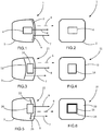
figure 9 est une vue en perspective avant d'un cinquième mode de réalisation d'un dispositif de signalisation selon l'invention. - La
figure 10 est une vue en perspective arrière du cinquième mode de réalisation du dispositif de signalisation selon l'invention. - La
figure 11 est une vue de face du cinquième mode de réalisation du dispositif de signalisation selon l'invention. - La
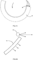
figure 12 est une vue en section verticale du cinquième mode de réalisation du dispositif de signalisation selon l'invention. - La
figure 13 est un schéma de principe d'un mode de réalisation d'une source surfacique de lumière pouvant être utilisé pour la mise en oeuvre d'un dispositif de signalisation selon l'invention. - La
figure 14 est un schéma de principe d'un mode de réalisation d'une autre source surfacique de lumière pouvant être utilisé pour la mise en oeuvre d'un dispositif de signalisation selon l'invention.
- The
figure 1 is a block diagram in section of a first embodiment of a signaling device according to the invention. - The
figure 2 is a block diagram in front view (without the housing) of the first embodiment of a signaling device according to the invention. - The
figure 3 is a block diagram in section of a second embodiment of a signaling device according to the invention. - The
figure 4 is a block diagram in front view (without the housing) of the second embodiment of a signaling device according to the invention. - The
figure 5 is a block diagram in section of a third embodiment of a signaling device according to the invention. - The
figure 6 is a block diagram in front view (without the housing) of the third embodiment of a signaling device according to the invention. - The
figure 7 is a block diagram in section of a fourth embodiment of a signaling device according to the invention. - The
figure 8 is a block diagram in front view (without the housing) of the fourth embodiment of a signaling device according to the invention. - The
figure 9 is a perspective view before a fifth embodiment of a signaling device according to the invention. - The
figure 10 is a rear perspective view of the fifth embodiment of the signaling device according to the invention. - The
figure 11 is a front view of the fifth embodiment of the signaling device according to the invention. - The
figure 12 is a vertical sectional view of the fifth embodiment of the signaling device according to the invention. - The
figure 13 is a block diagram of an embodiment of a surface source of light that can be used for the implementation of a signaling device according to the invention. - The
figure 14 is a block diagram of an embodiment of another surface source of light that can be used for the implementation of a signaling device according to the invention.
Dans un premier mode de réalisation, décrit ci-après en référence aux
Dans ce premier mode de réalisation, la source auxiliaire de lumière 2 est interposée entre la glace de fermeture 9 et la source principale de lumière 4. Ainsi, les rayons lumineux 7 émis par la source auxiliaire de lumière 2 atteignent directement la glace de fermeture pour sortir du dispositif de signalisation. Cependant, les rayons lumineux 8 émis par la source principale de lumière 4 atteignent indirectement la glace de fermeture : ils doivent au préalable traverser la source auxiliaire de lumière. Aussi, dans ce premier mode de réalisation, la source auxiliaire de lumière doit être du type transparent. Elle comprend de préférence une diode électroluminescente organique ayant deux électrodes transparentes. La source principale de lumière se trouvant derrière la source auxiliaire de lumière, elle est représentée en traits pointillés à la
Dans un deuxième mode de réalisation, décrit ci-après en référence aux
Dans un troisième mode de réalisation, décrit ci-après en référence aux
Dans deux variantes de réalisation, la source auxiliaire présente une découpe comme selon un exemple du troisième mode de réalisation, mais la source principale est en avant ou arrière de l'ouverture créée par la découpe. Par exemple, selon une première variante de réalisation, il est possible de substituer la source auxiliaire de lumière 22 du troisième mode de réalisation à la source de lumière auxiliaire 2 du premier mode de réalisation. Comparativement au premier mode de réalisation, le rendement photométrique de cette première variante sera amélioré. En effet, dans cette variante, il n'y a pas de perte de lumière émise par la source principale en traversant la source de lumière auxiliaire. Selon une deuxième variante de réalisation, il est possible de substituer la source auxiliaire de lumière 22 du troisième mode de réalisation à la source de lumière auxiliaire 12 du deuxième mode de réalisation. Dans ces deux variantes, on réduit le coût puisque la source de lumière auxiliaire présente une surface efficiente réduite, notamment si cette source de lumière auxiliaire est une OLED. De plus selon ces deux variantes, on obtient en plus un effet de profondeur.In two embodiments, the auxiliary source has a cutout as in an example of the third embodiment, but the main source is in front or rear of the opening created by the cut. For example, according to a first embodiment, it is possible to substitute the auxiliary
Dans un quatrième mode de réalisation, décrit ci-après en référence aux
Bien entendu, ce dernier mode de réalisation peut être combiné avec les deux premiers modes de réalisation. Ainsi, la source principale de lumière n'est pas nécessairement située au milieu ou sensiblement au milieu de la source auxiliaire de lumière, mais peut-être située au niveau d'un bord de cette dernière, que la source principale de lumière se trouve en avant, en arrière, ou au niveau de la source auxiliaire de lumière.Of course, this latter embodiment can be combined with the first two embodiments. Thus, the main source of light is not necessarily located in the middle or substantially in the middle of the auxiliary light source, but may be located at an edge thereof, that the main light source is in forward, backward, or at the auxiliary light source.
Dans un cinquième mode de réalisation, décrit ci-après en référence aux
Les rayons lumineux 8 émis par la source principale de lumière et les rayons lumineux 7 émis par la source auxiliaire de lumière peuvent être émis au moins sensiblement selon la même direction. Néanmoins, ils peuvent être aussi émis selon des directions très différentes pouvant par exemple former entre elles un angle allant jusqu'à 90° ou plus. En particulier, notamment dans des applications de feux à grande surface extérieure du type feux avec "retour d'aile", les rayons lumineux 8 émis par la source principale de lumière et les rayons lumineux 7 émis par la source auxiliaire de lumière peuvent être localement émis au moins sensiblement selon la même direction et localement émis selon des directions très différentes. En effet, la fonction de signalisation est réalisée au moins essentiellement par la source principale. La source auxiliaire a une fonction de signature.The light rays 8 emitted by the main source of light and the
Dans les différents modes de réalisation, la source auxiliaire de lumière est de type surfacique : elle comprend au moins une source surfacique de lumière, comprenant une diode électroluminescente organique. Un tel dispositif 70 de diode électroluminescente organique est représenté à la
Préférentiellement, l'aire émettrice de la source surfacique de lumière est supérieure à 1 cm2, voire supérieure à 10 cm2.Preferably, the emitting area of the surface light source is greater than 1 cm 2 , or even greater than 10 cm 2 .
La source auxiliaire de lumière peut comprendre plusieurs éléments surfaciques émettant de la lumière, notamment plusieurs diodes électroluminescentes organiques. Les différents éléments surfaciques de lumière peuvent être activés simultanément ou indépendamment les uns des autres. Les différents éléments peuvent être disposés jointivement ou non, éventuellement en orientant leurs plans d'émission différemment.The auxiliary light source may include a plurality of light-emitting surface elements, including a plurality of organic light-emitting diodes. The different surface elements of light can be activated simultaneously or independently of each other. The different elements can be arranged conjoined or not, possibly by orienting their emission plans differently.
La source auxiliaire de lumière peut être lambertienne ou non.The auxiliary light source may be Lambertian or not.
De préférence, la source auxiliaire est réalisée par une diode électroluminescente organique conformable. Par exemple, elle peut être réalisée par un film qu'il est possible de déposer sur une surface, notamment sur une surface gauche. Alternativement, elle peut être réalisée grâce à une technique d'impression des différentes couches, notamment par une technique d'impression sur une surface gauche. Ainsi, la source auxiliaire de lumière peut avoir une forme permettant de suivre le galbe de la glace de fermeture 9 du dispositif de signalisation.Preferably, the auxiliary source is formed by a conformable organic light-emitting diode. For example, it can be made by a film that can be deposited on a surface, especially on a left surface. Alternatively, it can be performed using a printing technique of the various layers, in particular by a printing technique on a left surface. Thus, the auxiliary light source may have a shape making it possible to follow the curve of the
La source principale de lumière peut être de tous types. De préférence, elle comprend une ou plusieurs lampes associées à un réflecteur ou une ou plusieurs diodes électroluminescentes, ou LED, associées à un réflecteur. Elle peut aussi comprendre un système de lentilles optiques. La source principale de lumière peut comprendre une diode électroluminescente organique. Un tel dispositif 60 de diode électroluminescente organique est représenté à la
Selon des modes de réalisations, il est possible de prévoir que les sources principale et auxiliaire de lumière émettent de la lumière de couleurs différentes, les fonctions assurées par les deux sources pouvant nécessiter des couleurs différentes.According to embodiments, it is possible to provide that the main and auxiliary sources of light emit light of different colors, the functions provided by the two sources may require different colors.
Selon un mode de réalisation préféré, les sources principale et auxiliaire de lumière sont activées simultanément.According to a preferred embodiment, the main and auxiliary sources of light are activated simultaneously.
La source principale de lumière et la source auxiliaire de lumière n'assurent pas plus d'une fonction de signalisation. La source auxiliaire de lumière complète la source principale de lumière pour assurer la fonction de signalisation.The main light source and the auxiliary light source do not provide more than one signaling function. The auxiliary light source completes the main light source to provide the signaling function.
Dans le cas où la source auxiliaire de lumière est réalisée par plusieurs éléments surfaciques émettant de la lumière, il est possible de réaliser plusieurs zones pouvant être allumées indépendamment les unes des autres. Il est également possible d'éteindre une zone lorsque la source principale est allumée.In the case where the auxiliary light source is made by several surface elements emitting light, it is possible to achieve several zones that can be ignited independently of each other. It is also possible to turn off an area when the main source is on.
Le dispositif de signalisation selon l'invention permet par exemple d'assurer l'une des fonctions suivantes : signalisation de position du véhicule, signalisation de changement de direction, signalisation de recul, signalisation de freinage, signalisation en cas de brouillard.The signaling device according to the invention makes it possible, for example, to perform one of the following functions: vehicle position signaling, direction change signaling, reversing signaling, braking signaling, signaling in the event of fog.
Claims (13)
- Optical signalling device (1; 11; 21; 31; 41) for a motor-vehicle, comprising a main light source (4; 14; 24; 34; 44) and an auxiliary light source (2; 12; 22; 32; 42), the auxiliary light source comprising an areal light source comprising an organic light-emitting diode (2; 12; 22; 32; 42), characterized in that the main light source and the auxiliary light source provide no more than one signalling function, the signalling function being a photometric function that is useful to the vehicle when it is being driven on-road, and that allows the vehicle to be seen by other vehicles.
- Device according to the preceding claim, characterized in that the emission area of the areal light source is larger than 1 cm2, or even larger than 10 cm2.
- Device according to one of the preceding claims, characterized in that the organic light-emitting diode (2; 12; 22; 32; 42) is conformable.
- Device according to one of the preceding claims, characterized in that the signalling device comprises a casing (3) that is closed by a closing outer lens (9), inside of which casing the auxiliary and main light sources are located.
- Device according to the preceding claim, characterized in that the auxiliary light source (2) is located interposed between the closing outer lens and the main light source (4) and in that the auxiliary light source (2) is of transparent type.
- Device (11) according to Claim 4, characterized in that the main light source (12) is located placed between the closing outer lens and the auxiliary light source (14).
- Device (21; 31) according to one of Claims 1 to 4, characterized in that the auxiliary light source (22; 32) contains a notch (25; 35) in which the main light source (24; 34) is arranged.
- Device according to one of the preceding claims, characterized in that the main light source (34) is arranged level with an edge of the signalling device and/or level with an edge (36) of the auxiliary light source.
- Device according to one of the preceding claims, characterized in that the main light source comprises a plurality of light-emitting elements.
- Device according to one of the preceding claims, characterized in that the auxiliary light source comprises a plurality of areal light-emitting elements, in particular a plurality of organic light-emitting diodes.
- Device according to one of the preceding claims, characterized in that the main light source and the auxiliary light source are activated simultaneously.
- Device according to one of the preceding claims, characterized in that most of the signalling function is provided by the main source.
- Device according to one of the preceding claims, characterized in that it is intended to provide a signalling function of a motor vehicle.
Applications Claiming Priority (2)
| Application Number | Priority Date | Filing Date | Title |
|---|---|---|---|
| FR1051610A FR2957133B1 (en) | 2010-03-05 | 2010-03-05 | DEVICE FOR LIGHTING AND / OR SIGNALING A MOTOR VEHICLE COMPRISING A SURFACE SOURCE OF LIGHT |
| PCT/EP2011/052394 WO2011107352A1 (en) | 2010-03-05 | 2011-02-18 | Lighting and/or signaling device for a motor including a surface light source |
Publications (2)
| Publication Number | Publication Date |
|---|---|
| EP2542828A1 EP2542828A1 (en) | 2013-01-09 |
| EP2542828B1 true EP2542828B1 (en) | 2018-09-05 |
Family
ID=42752002
Family Applications (1)
| Application Number | Title | Priority Date | Filing Date |
|---|---|---|---|
| EP11704972.6A Active EP2542828B1 (en) | 2010-03-05 | 2011-02-18 | Signaling device for a motor including a surface light source |
Country Status (5)
| Country | Link |
|---|---|
| US (1) | US20130027960A1 (en) |
| EP (1) | EP2542828B1 (en) |
| CN (1) | CN102782401B (en) |
| FR (1) | FR2957133B1 (en) |
| WO (1) | WO2011107352A1 (en) |
Families Citing this family (11)
| Publication number | Priority date | Publication date | Assignee | Title |
|---|---|---|---|---|
| CN103244862B (en) * | 2012-02-06 | 2015-07-08 | 夏建新 | Solid double-light-source module and cold light shadowless illumination device |
| DE102012107644A1 (en) * | 2012-08-21 | 2014-03-27 | Hella Kgaa Hueck & Co. | Lighting unit for a motor vehicle |
| US20140328078A1 (en) * | 2013-05-03 | 2014-11-06 | Ford Global Technologies Llc | Vehicle headlamp assmebly |
| AT514217B1 (en) | 2013-05-08 | 2016-02-15 | Zizala Lichtsysteme Gmbh | Lighting device for motor vehicles |
| DE102014211963A1 (en) * | 2014-06-23 | 2015-12-24 | Volkswagen Aktiengesellschaft | Automotive lighting device |
| EP3009300B1 (en) * | 2014-10-13 | 2021-01-06 | MARELLI AUTOMOTIVE LIGHTING ITALY S.p.A. | Automotive light |
| CZ2015769A3 (en) * | 2015-10-30 | 2016-12-14 | Varroc Lighting Systems, s.r.o. | Lighting installation especially motor vehicle signal light |
| DE102016111330A1 (en) * | 2016-06-21 | 2017-12-21 | Osram Oled Gmbh | Light emitting device |
| US20180017224A1 (en) * | 2016-07-12 | 2018-01-18 | GM Global Technology Operations LLC | Vehicle lamp assembly with rear-lit oled |
| FR3065779B1 (en) * | 2017-04-26 | 2020-08-07 | Peugeot Citroen Automobiles Sa | LIGHTING DEVICE FOR MOTOR VEHICLES INCLUDING A MAIN SOURCE OF LIGHT ASSOCIATED WITH A REFLECTIVE OLED |
| IT201800005869A1 (en) * | 2018-05-30 | 2019-11-30 | SIGNALING SYSTEM FOR THE OUTSIDE OF A VEHICLE |
Citations (3)
| Publication number | Priority date | Publication date | Assignee | Title |
|---|---|---|---|---|
| WO2005007450A1 (en) * | 2003-07-15 | 2005-01-27 | Daimlerchrysler Ag | Interior lamp, especially for a vehicle |
| DE102007021865A1 (en) * | 2007-05-10 | 2008-11-13 | Automotive Lighting Reutlingen Gmbh | Lighting device for vehicle, especially motor vehicle, has cover frame with organic light emitting diodes visible from outside through cover panel and that emit light to implement at least some lighting functions when activated |
| US20090262545A1 (en) * | 2008-04-21 | 2009-10-22 | Joerg Amelung | Illumination Apparatus and Method of Producing a Planar Light Output |
Family Cites Families (21)
| Publication number | Priority date | Publication date | Assignee | Title |
|---|---|---|---|---|
| JPH0795401B2 (en) * | 1988-04-05 | 1995-10-11 | 株式会社小糸製作所 | Automotive headlights |
| DE10022420B4 (en) * | 2000-05-09 | 2007-04-26 | Automotive Lighting Reutlingen Gmbh | vehicle light |
| FR2819040B1 (en) * | 2001-01-02 | 2003-09-12 | Valeo Vision | OPTICAL OR STYLE COMPONENT FOR A LIGHTING OR SIGNALING DEVICE FOR A MOTOR VEHICLE |
| JP3933895B2 (en) * | 2001-08-08 | 2007-06-20 | 株式会社小糸製作所 | Vehicle headlamp device |
| US20030212388A1 (en) * | 2002-05-13 | 2003-11-13 | Ronn Avigdor M. | Treatment of localized pain with a flexible conformational array of light |
| AU2003298561A1 (en) * | 2002-08-23 | 2004-05-13 | Jonathan S. Dahm | Method and apparatus for using light emitting diodes |
| JP2004103379A (en) * | 2002-09-09 | 2004-04-02 | Koito Mfg Co Ltd | Marker lamp for vehicle |
| FR2849157B1 (en) | 2002-12-20 | 2015-07-10 | Valeo Vision | DEVICE FOR LIGHTING AND / OR SIGNALING THE PROJECTOR OR FIRE TYPE FOR A MOTOR VEHICLE |
| CN2604609Y (en) * | 2003-01-24 | 2004-02-25 | 胡文松 | Anti-fogging structure |
| DE102004004398A1 (en) * | 2003-05-23 | 2004-12-09 | Volkswagen Ag | Headlights or lights for a motor vehicle |
| JP2007505475A (en) * | 2003-05-23 | 2007-03-08 | フオルクスヴアーゲン アクチエンゲゼルシヤフト | Headlights or lamps used in automobiles |
| GB2405755B (en) * | 2003-09-04 | 2006-07-05 | Shaukat Consultants Ltd | Lamps for a road vehicle |
| DE102004002251A1 (en) * | 2004-01-15 | 2005-08-04 | Zumtobel Staff Gmbh | Luminaire with different colored light sources and a light guide plate for emitting mixed light |
| GB2410116A (en) * | 2004-01-17 | 2005-07-20 | Sharp Kk | Illumination system and display device |
| DE102004020122B4 (en) * | 2004-04-24 | 2007-06-06 | Diehl Aerospace Gmbh | LED tubes hybrid lighting device |
| CN2842171Y (en) * | 2005-10-31 | 2006-11-29 | 江珏 | A kind of light source assembly |
| JP4676865B2 (en) * | 2005-11-08 | 2011-04-27 | 株式会社小糸製作所 | Vehicle lighting device |
| JP5261684B2 (en) * | 2007-11-27 | 2013-08-14 | スタンレー電気株式会社 | Strobe device |
| FR2926677B1 (en) | 2008-01-18 | 2014-04-25 | Astron Fiamm Safety | DIODE AND METHOD FOR PRODUCING A MICROCAVITY ORGANIC ELECTROLUMINESCENT DIODE INCLUDING DOPED ORGANIC LAYERS |
| US20090296370A1 (en) * | 2008-06-03 | 2009-12-03 | Gregory Nordin | Photo luminescent light source |
| JP2010021202A (en) * | 2008-07-08 | 2010-01-28 | Ushio Inc | Light emitting device |
-
2010
- 2010-03-05 FR FR1051610A patent/FR2957133B1/en active Active
-
2011
- 2011-02-18 EP EP11704972.6A patent/EP2542828B1/en active Active
- 2011-02-18 US US13/575,109 patent/US20130027960A1/en not_active Abandoned
- 2011-02-18 WO PCT/EP2011/052394 patent/WO2011107352A1/en active Application Filing
- 2011-02-18 CN CN201180012244.6A patent/CN102782401B/en active Active
Patent Citations (3)
| Publication number | Priority date | Publication date | Assignee | Title |
|---|---|---|---|---|
| WO2005007450A1 (en) * | 2003-07-15 | 2005-01-27 | Daimlerchrysler Ag | Interior lamp, especially for a vehicle |
| DE102007021865A1 (en) * | 2007-05-10 | 2008-11-13 | Automotive Lighting Reutlingen Gmbh | Lighting device for vehicle, especially motor vehicle, has cover frame with organic light emitting diodes visible from outside through cover panel and that emit light to implement at least some lighting functions when activated |
| US20090262545A1 (en) * | 2008-04-21 | 2009-10-22 | Joerg Amelung | Illumination Apparatus and Method of Producing a Planar Light Output |
Also Published As
| Publication number | Publication date |
|---|---|
| CN102782401B (en) | 2016-08-17 |
| FR2957133B1 (en) | 2015-08-21 |
| CN102782401A (en) | 2012-11-14 |
| EP2542828A1 (en) | 2013-01-09 |
| WO2011107352A1 (en) | 2011-09-09 |
| FR2957133A1 (en) | 2011-09-09 |
| US20130027960A1 (en) | 2013-01-31 |
Similar Documents
| Publication | Publication Date | Title |
|---|---|---|
| EP2542828B1 (en) | Signaling device for a motor including a surface light source | |
| EP2536972B1 (en) | Optical device for a motor vehicle including a surface light source | |
| EP1637397B1 (en) | Lighting assembly with daytime running light (DRL) for vehicles | |
| EP2453167A1 (en) | Lighting and/or signalling device for an automobile comprising a surface light source | |
| EP2536973B1 (en) | Optical system for a motor vehicle | |
| EP3002504A2 (en) | Lighting module for lighting and/or signalling of a motor vehicle | |
| FR3039880B1 (en) | LIGHTING AND / OR SIGNALING DEVICE FOR MOTOR VEHICLE | |
| EP2317214A1 (en) | Lighting or signalling device for an automobile comprising a light guide | |
| EP3127747A1 (en) | Lighting and/or signalling device for a motor vehicle | |
| WO2011092052A1 (en) | Optical device for a motor vehicle including a surface light source | |
| EP3267096A1 (en) | Lighting and/or signalling device for a motor vehicle | |
| EP2505911A2 (en) | Optical device of an automobile performing a plurality of functions. | |
| WO2017025440A1 (en) | Lighting and/or signalling device for a motor vehicle | |
| EP3024699A1 (en) | Lighting system, in particular for a motor vehicle lighting member, comprising a light-emitting element offset from the light source | |
| FR3052145A1 (en) | LIGHTING DEVICE FOR INTERIOR SPACE OF A VEHICLE | |
| FR3025286A1 (en) | LIGHTING AND / OR SIGNALING DEVICE FOR MOTOR VEHICLE | |
| WO2014083262A1 (en) | Vehicle signalling device with three-dimensional effect | |
| FR3007501A1 (en) | DEVICE FOR LIGHTING A VEHICLE USING A MULTIFUNCTION OPTICAL LENS | |
| EP2712765B1 (en) | Lighting device with a light-source module having two emitting surfaces | |
| FR2982658A1 (en) | OPTICAL DEVICE COMPRISING A PLURALITY OF REFLECTIVE FACES | |
| EP2770249A1 (en) | Vehicle headlamp | |
| FR2995968A1 (en) | LIGHTING AND / OR SIGNALING DEVICE FOR A VEHICLE COMPRISING A LENS AND A SOURCE | |
| EP3124856A1 (en) | Lighting device for a motor vehicle | |
| FR3062708A1 (en) | VEHICLE OPTICAL BLOCK WITH INTERNAL SIDE AND VISIBLE FROM OUTSIDE | |
| WO2017025444A1 (en) | Lighting and/or signalling device for a motor vehicle |
Legal Events
| Date | Code | Title | Description |
|---|---|---|---|
| PUAI | Public reference made under article 153(3) epc to a published international application that has entered the european phase |
Free format text: ORIGINAL CODE: 0009012 |
|
| 17P | Request for examination filed |
Effective date: 20120717 |
|
| AK | Designated contracting states |
Kind code of ref document: A1 Designated state(s): AL AT BE BG CH CY CZ DE DK EE ES FI FR GB GR HR HU IE IS IT LI LT LU LV MC MK MT NL NO PL PT RO RS SE SI SK SM TR |
|
| DAX | Request for extension of the european patent (deleted) | ||
| 17Q | First examination report despatched |
Effective date: 20160520 |
|
| STAA | Information on the status of an ep patent application or granted ep patent |
Free format text: STATUS: EXAMINATION IS IN PROGRESS |
|
| REG | Reference to a national code |
Ref country code: DE Ref legal event code: R079 Ref document number: 602011051727 Country of ref document: DE Free format text: PREVIOUS MAIN CLASS: F21S0008120000 Ipc: F21S0043145000 |
|
| GRAP | Despatch of communication of intention to grant a patent |
Free format text: ORIGINAL CODE: EPIDOSNIGR1 |
|
| STAA | Information on the status of an ep patent application or granted ep patent |
Free format text: STATUS: GRANT OF PATENT IS INTENDED |
|
| RIC1 | Information provided on ipc code assigned before grant |
Ipc: F21S 43/145 20180101AFI20180221BHEP Ipc: F21S 43/00 20180101ALI20180221BHEP |
|
| INTG | Intention to grant announced |
Effective date: 20180321 |
|
| GRAS | Grant fee paid |
Free format text: ORIGINAL CODE: EPIDOSNIGR3 |
|
| GRAA | (expected) grant |
Free format text: ORIGINAL CODE: 0009210 |
|
| STAA | Information on the status of an ep patent application or granted ep patent |
Free format text: STATUS: THE PATENT HAS BEEN GRANTED |
|
| AK | Designated contracting states |
Kind code of ref document: B1 Designated state(s): AL AT BE BG CH CY CZ DE DK EE ES FI FR GB GR HR HU IE IS IT LI LT LU LV MC MK MT NL NO PL PT RO RS SE SI SK SM TR |
|
| REG | Reference to a national code |
Ref country code: GB Ref legal event code: FG4D Free format text: NOT ENGLISH |
|
| REG | Reference to a national code |
Ref country code: CH Ref legal event code: EP |
|
| REG | Reference to a national code |
Ref country code: AT Ref legal event code: REF Ref document number: 1038234 Country of ref document: AT Kind code of ref document: T Effective date: 20180915 |
|
| REG | Reference to a national code |
Ref country code: IE Ref legal event code: FG4D Free format text: LANGUAGE OF EP DOCUMENT: FRENCH |
|
| REG | Reference to a national code |
Ref country code: DE Ref legal event code: R096 Ref document number: 602011051727 Country of ref document: DE |
|
| REG | Reference to a national code |
Ref country code: NL Ref legal event code: MP Effective date: 20180905 |
|
| REG | Reference to a national code |
Ref country code: LT Ref legal event code: MG4D |
|
| PG25 | Lapsed in a contracting state [announced via postgrant information from national office to epo] |
Ref country code: SE Free format text: LAPSE BECAUSE OF FAILURE TO SUBMIT A TRANSLATION OF THE DESCRIPTION OR TO PAY THE FEE WITHIN THE PRESCRIBED TIME-LIMIT Effective date: 20180905 Ref country code: GR Free format text: LAPSE BECAUSE OF FAILURE TO SUBMIT A TRANSLATION OF THE DESCRIPTION OR TO PAY THE FEE WITHIN THE PRESCRIBED TIME-LIMIT Effective date: 20181206 Ref country code: RS Free format text: LAPSE BECAUSE OF FAILURE TO SUBMIT A TRANSLATION OF THE DESCRIPTION OR TO PAY THE FEE WITHIN THE PRESCRIBED TIME-LIMIT Effective date: 20180905 Ref country code: BG Free format text: LAPSE BECAUSE OF FAILURE TO SUBMIT A TRANSLATION OF THE DESCRIPTION OR TO PAY THE FEE WITHIN THE PRESCRIBED TIME-LIMIT Effective date: 20181205 Ref country code: LT Free format text: LAPSE BECAUSE OF FAILURE TO SUBMIT A TRANSLATION OF THE DESCRIPTION OR TO PAY THE FEE WITHIN THE PRESCRIBED TIME-LIMIT Effective date: 20180905 Ref country code: FI Free format text: LAPSE BECAUSE OF FAILURE TO SUBMIT A TRANSLATION OF THE DESCRIPTION OR TO PAY THE FEE WITHIN THE PRESCRIBED TIME-LIMIT Effective date: 20180905 Ref country code: NO Free format text: LAPSE BECAUSE OF FAILURE TO SUBMIT A TRANSLATION OF THE DESCRIPTION OR TO PAY THE FEE WITHIN THE PRESCRIBED TIME-LIMIT Effective date: 20181205 |
|
| REG | Reference to a national code |
Ref country code: AT Ref legal event code: MK05 Ref document number: 1038234 Country of ref document: AT Kind code of ref document: T Effective date: 20180905 |
|
| PG25 | Lapsed in a contracting state [announced via postgrant information from national office to epo] |
Ref country code: LV Free format text: LAPSE BECAUSE OF FAILURE TO SUBMIT A TRANSLATION OF THE DESCRIPTION OR TO PAY THE FEE WITHIN THE PRESCRIBED TIME-LIMIT Effective date: 20180905 Ref country code: HR Free format text: LAPSE BECAUSE OF FAILURE TO SUBMIT A TRANSLATION OF THE DESCRIPTION OR TO PAY THE FEE WITHIN THE PRESCRIBED TIME-LIMIT Effective date: 20180905 Ref country code: AL Free format text: LAPSE BECAUSE OF FAILURE TO SUBMIT A TRANSLATION OF THE DESCRIPTION OR TO PAY THE FEE WITHIN THE PRESCRIBED TIME-LIMIT Effective date: 20180905 |
|
| PG25 | Lapsed in a contracting state [announced via postgrant information from national office to epo] |
Ref country code: RO Free format text: LAPSE BECAUSE OF FAILURE TO SUBMIT A TRANSLATION OF THE DESCRIPTION OR TO PAY THE FEE WITHIN THE PRESCRIBED TIME-LIMIT Effective date: 20180905 Ref country code: CZ Free format text: LAPSE BECAUSE OF FAILURE TO SUBMIT A TRANSLATION OF THE DESCRIPTION OR TO PAY THE FEE WITHIN THE PRESCRIBED TIME-LIMIT Effective date: 20180905 Ref country code: IT Free format text: LAPSE BECAUSE OF FAILURE TO SUBMIT A TRANSLATION OF THE DESCRIPTION OR TO PAY THE FEE WITHIN THE PRESCRIBED TIME-LIMIT Effective date: 20180905 Ref country code: EE Free format text: LAPSE BECAUSE OF FAILURE TO SUBMIT A TRANSLATION OF THE DESCRIPTION OR TO PAY THE FEE WITHIN THE PRESCRIBED TIME-LIMIT Effective date: 20180905 Ref country code: AT Free format text: LAPSE BECAUSE OF FAILURE TO SUBMIT A TRANSLATION OF THE DESCRIPTION OR TO PAY THE FEE WITHIN THE PRESCRIBED TIME-LIMIT Effective date: 20180905 Ref country code: ES Free format text: LAPSE BECAUSE OF FAILURE TO SUBMIT A TRANSLATION OF THE DESCRIPTION OR TO PAY THE FEE WITHIN THE PRESCRIBED TIME-LIMIT Effective date: 20180905 Ref country code: NL Free format text: LAPSE BECAUSE OF FAILURE TO SUBMIT A TRANSLATION OF THE DESCRIPTION OR TO PAY THE FEE WITHIN THE PRESCRIBED TIME-LIMIT Effective date: 20180905 Ref country code: PL Free format text: LAPSE BECAUSE OF FAILURE TO SUBMIT A TRANSLATION OF THE DESCRIPTION OR TO PAY THE FEE WITHIN THE PRESCRIBED TIME-LIMIT Effective date: 20180905 Ref country code: IS Free format text: LAPSE BECAUSE OF FAILURE TO SUBMIT A TRANSLATION OF THE DESCRIPTION OR TO PAY THE FEE WITHIN THE PRESCRIBED TIME-LIMIT Effective date: 20190105 |
|
| PG25 | Lapsed in a contracting state [announced via postgrant information from national office to epo] |
Ref country code: SK Free format text: LAPSE BECAUSE OF FAILURE TO SUBMIT A TRANSLATION OF THE DESCRIPTION OR TO PAY THE FEE WITHIN THE PRESCRIBED TIME-LIMIT Effective date: 20180905 Ref country code: PT Free format text: LAPSE BECAUSE OF FAILURE TO SUBMIT A TRANSLATION OF THE DESCRIPTION OR TO PAY THE FEE WITHIN THE PRESCRIBED TIME-LIMIT Effective date: 20190105 Ref country code: SM Free format text: LAPSE BECAUSE OF FAILURE TO SUBMIT A TRANSLATION OF THE DESCRIPTION OR TO PAY THE FEE WITHIN THE PRESCRIBED TIME-LIMIT Effective date: 20180905 |
|
| REG | Reference to a national code |
Ref country code: DE Ref legal event code: R097 Ref document number: 602011051727 Country of ref document: DE |
|
| PLBE | No opposition filed within time limit |
Free format text: ORIGINAL CODE: 0009261 |
|
| STAA | Information on the status of an ep patent application or granted ep patent |
Free format text: STATUS: NO OPPOSITION FILED WITHIN TIME LIMIT |
|
| PG25 | Lapsed in a contracting state [announced via postgrant information from national office to epo] |
Ref country code: DK Free format text: LAPSE BECAUSE OF FAILURE TO SUBMIT A TRANSLATION OF THE DESCRIPTION OR TO PAY THE FEE WITHIN THE PRESCRIBED TIME-LIMIT Effective date: 20180905 |
|
| 26N | No opposition filed |
Effective date: 20190606 |
|
| PG25 | Lapsed in a contracting state [announced via postgrant information from national office to epo] |
Ref country code: SI Free format text: LAPSE BECAUSE OF FAILURE TO SUBMIT A TRANSLATION OF THE DESCRIPTION OR TO PAY THE FEE WITHIN THE PRESCRIBED TIME-LIMIT Effective date: 20180905 |
|
| REG | Reference to a national code |
Ref country code: CH Ref legal event code: PL |
|
| GBPC | Gb: european patent ceased through non-payment of renewal fee |
Effective date: 20190218 |
|
| PG25 | Lapsed in a contracting state [announced via postgrant information from national office to epo] |
Ref country code: MC Free format text: LAPSE BECAUSE OF FAILURE TO SUBMIT A TRANSLATION OF THE DESCRIPTION OR TO PAY THE FEE WITHIN THE PRESCRIBED TIME-LIMIT Effective date: 20180905 Ref country code: LU Free format text: LAPSE BECAUSE OF NON-PAYMENT OF DUE FEES Effective date: 20190218 |
|
| REG | Reference to a national code |
Ref country code: BE Ref legal event code: MM Effective date: 20190228 |
|
| REG | Reference to a national code |
Ref country code: IE Ref legal event code: MM4A |
|
| PG25 | Lapsed in a contracting state [announced via postgrant information from national office to epo] |
Ref country code: CH Free format text: LAPSE BECAUSE OF NON-PAYMENT OF DUE FEES Effective date: 20190228 Ref country code: LI Free format text: LAPSE BECAUSE OF NON-PAYMENT OF DUE FEES Effective date: 20190228 |
|
| PG25 | Lapsed in a contracting state [announced via postgrant information from national office to epo] |
Ref country code: IE Free format text: LAPSE BECAUSE OF NON-PAYMENT OF DUE FEES Effective date: 20190218 Ref country code: GB Free format text: LAPSE BECAUSE OF NON-PAYMENT OF DUE FEES Effective date: 20190218 |
|
| PG25 | Lapsed in a contracting state [announced via postgrant information from national office to epo] |
Ref country code: BE Free format text: LAPSE BECAUSE OF NON-PAYMENT OF DUE FEES Effective date: 20190228 |
|
| PG25 | Lapsed in a contracting state [announced via postgrant information from national office to epo] |
Ref country code: TR Free format text: LAPSE BECAUSE OF FAILURE TO SUBMIT A TRANSLATION OF THE DESCRIPTION OR TO PAY THE FEE WITHIN THE PRESCRIBED TIME-LIMIT Effective date: 20180905 |
|
| PG25 | Lapsed in a contracting state [announced via postgrant information from national office to epo] |
Ref country code: MT Free format text: LAPSE BECAUSE OF FAILURE TO SUBMIT A TRANSLATION OF THE DESCRIPTION OR TO PAY THE FEE WITHIN THE PRESCRIBED TIME-LIMIT Effective date: 20180905 |
|
| PG25 | Lapsed in a contracting state [announced via postgrant information from national office to epo] |
Ref country code: CY Free format text: LAPSE BECAUSE OF FAILURE TO SUBMIT A TRANSLATION OF THE DESCRIPTION OR TO PAY THE FEE WITHIN THE PRESCRIBED TIME-LIMIT Effective date: 20180905 |
|
| PG25 | Lapsed in a contracting state [announced via postgrant information from national office to epo] |
Ref country code: HU Free format text: LAPSE BECAUSE OF FAILURE TO SUBMIT A TRANSLATION OF THE DESCRIPTION OR TO PAY THE FEE WITHIN THE PRESCRIBED TIME-LIMIT; INVALID AB INITIO Effective date: 20110218 |
|
| PG25 | Lapsed in a contracting state [announced via postgrant information from national office to epo] |
Ref country code: MK Free format text: LAPSE BECAUSE OF FAILURE TO SUBMIT A TRANSLATION OF THE DESCRIPTION OR TO PAY THE FEE WITHIN THE PRESCRIBED TIME-LIMIT Effective date: 20180905 |
|
| PGFP | Annual fee paid to national office [announced via postgrant information from national office to epo] |
Ref country code: FR Payment date: 20230227 Year of fee payment: 13 |
|
| PGFP | Annual fee paid to national office [announced via postgrant information from national office to epo] |
Ref country code: DE Payment date: 20230207 Year of fee payment: 13 |
|
| P01 | Opt-out of the competence of the unified patent court (upc) registered |
Effective date: 20230528 |