EP2542421B1 - Security element having aligned magnetic pigments - Google Patents
Security element having aligned magnetic pigments Download PDFInfo
- Publication number
- EP2542421B1 EP2542421B1 EP11706491.5A EP11706491A EP2542421B1 EP 2542421 B1 EP2542421 B1 EP 2542421B1 EP 11706491 A EP11706491 A EP 11706491A EP 2542421 B1 EP2542421 B1 EP 2542421B1
- Authority
- EP
- European Patent Office
- Prior art keywords
- pigments
- motif
- magnetic pigments
- security element
- ink layer
- Prior art date
- Legal status (The legal status is an assumption and is not a legal conclusion. Google has not performed a legal analysis and makes no representation as to the accuracy of the status listed.)
- Active
Links
Images


Classifications
-
- B—PERFORMING OPERATIONS; TRANSPORTING
- B05—SPRAYING OR ATOMISING IN GENERAL; APPLYING FLUENT MATERIALS TO SURFACES, IN GENERAL
- B05D—PROCESSES FOR APPLYING FLUENT MATERIALS TO SURFACES, IN GENERAL
- B05D3/00—Pretreatment of surfaces to which liquids or other fluent materials are to be applied; After-treatment of applied coatings, e.g. intermediate treating of an applied coating preparatory to subsequent applications of liquids or other fluent materials
- B05D3/06—Pretreatment of surfaces to which liquids or other fluent materials are to be applied; After-treatment of applied coatings, e.g. intermediate treating of an applied coating preparatory to subsequent applications of liquids or other fluent materials by exposure to radiation
-
- B—PERFORMING OPERATIONS; TRANSPORTING
- B42—BOOKBINDING; ALBUMS; FILES; SPECIAL PRINTED MATTER
- B42D—BOOKS; BOOK COVERS; LOOSE LEAVES; PRINTED MATTER CHARACTERISED BY IDENTIFICATION OR SECURITY FEATURES; PRINTED MATTER OF SPECIAL FORMAT OR STYLE NOT OTHERWISE PROVIDED FOR; DEVICES FOR USE THEREWITH AND NOT OTHERWISE PROVIDED FOR; MOVABLE-STRIP WRITING OR READING APPARATUS
- B42D25/00—Information-bearing cards or sheet-like structures characterised by identification or security features; Manufacture thereof
- B42D25/20—Information-bearing cards or sheet-like structures characterised by identification or security features; Manufacture thereof characterised by a particular use or purpose
-
- B—PERFORMING OPERATIONS; TRANSPORTING
- B05—SPRAYING OR ATOMISING IN GENERAL; APPLYING FLUENT MATERIALS TO SURFACES, IN GENERAL
- B05D—PROCESSES FOR APPLYING FLUENT MATERIALS TO SURFACES, IN GENERAL
- B05D3/00—Pretreatment of surfaces to which liquids or other fluent materials are to be applied; After-treatment of applied coatings, e.g. intermediate treating of an applied coating preparatory to subsequent applications of liquids or other fluent materials
- B05D3/20—Pretreatment of surfaces to which liquids or other fluent materials are to be applied; After-treatment of applied coatings, e.g. intermediate treating of an applied coating preparatory to subsequent applications of liquids or other fluent materials by magnetic fields
- B05D3/207—Pretreatment of surfaces to which liquids or other fluent materials are to be applied; After-treatment of applied coatings, e.g. intermediate treating of an applied coating preparatory to subsequent applications of liquids or other fluent materials by magnetic fields post-treatment by magnetic fields
-
- B—PERFORMING OPERATIONS; TRANSPORTING
- B05—SPRAYING OR ATOMISING IN GENERAL; APPLYING FLUENT MATERIALS TO SURFACES, IN GENERAL
- B05D—PROCESSES FOR APPLYING FLUENT MATERIALS TO SURFACES, IN GENERAL
- B05D5/00—Processes for applying liquids or other fluent materials to surfaces to obtain special surface effects, finishes or structures
- B05D5/06—Processes for applying liquids or other fluent materials to surfaces to obtain special surface effects, finishes or structures to obtain multicolour or other optical effects
- B05D5/061—Special surface effect
-
- B—PERFORMING OPERATIONS; TRANSPORTING
- B42—BOOKBINDING; ALBUMS; FILES; SPECIAL PRINTED MATTER
- B42D—BOOKS; BOOK COVERS; LOOSE LEAVES; PRINTED MATTER CHARACTERISED BY IDENTIFICATION OR SECURITY FEATURES; PRINTED MATTER OF SPECIAL FORMAT OR STYLE NOT OTHERWISE PROVIDED FOR; DEVICES FOR USE THEREWITH AND NOT OTHERWISE PROVIDED FOR; MOVABLE-STRIP WRITING OR READING APPARATUS
- B42D25/00—Information-bearing cards or sheet-like structures characterised by identification or security features; Manufacture thereof
- B42D25/20—Information-bearing cards or sheet-like structures characterised by identification or security features; Manufacture thereof characterised by a particular use or purpose
- B42D25/29—Securities; Bank notes
-
- B—PERFORMING OPERATIONS; TRANSPORTING
- B42—BOOKBINDING; ALBUMS; FILES; SPECIAL PRINTED MATTER
- B42D—BOOKS; BOOK COVERS; LOOSE LEAVES; PRINTED MATTER CHARACTERISED BY IDENTIFICATION OR SECURITY FEATURES; PRINTED MATTER OF SPECIAL FORMAT OR STYLE NOT OTHERWISE PROVIDED FOR; DEVICES FOR USE THEREWITH AND NOT OTHERWISE PROVIDED FOR; MOVABLE-STRIP WRITING OR READING APPARATUS
- B42D25/00—Information-bearing cards or sheet-like structures characterised by identification or security features; Manufacture thereof
- B42D25/30—Identification or security features, e.g. for preventing forgery
- B42D25/36—Identification or security features, e.g. for preventing forgery comprising special materials
- B42D25/369—Magnetised or magnetisable materials
-
- B—PERFORMING OPERATIONS; TRANSPORTING
- B42—BOOKBINDING; ALBUMS; FILES; SPECIAL PRINTED MATTER
- B42D—BOOKS; BOOK COVERS; LOOSE LEAVES; PRINTED MATTER CHARACTERISED BY IDENTIFICATION OR SECURITY FEATURES; PRINTED MATTER OF SPECIAL FORMAT OR STYLE NOT OTHERWISE PROVIDED FOR; DEVICES FOR USE THEREWITH AND NOT OTHERWISE PROVIDED FOR; MOVABLE-STRIP WRITING OR READING APPARATUS
- B42D25/00—Information-bearing cards or sheet-like structures characterised by identification or security features; Manufacture thereof
- B42D25/40—Manufacture
- B42D25/405—Marking
- B42D25/41—Marking using electromagnetic radiation
-
- B—PERFORMING OPERATIONS; TRANSPORTING
- B05—SPRAYING OR ATOMISING IN GENERAL; APPLYING FLUENT MATERIALS TO SURFACES, IN GENERAL
- B05D—PROCESSES FOR APPLYING FLUENT MATERIALS TO SURFACES, IN GENERAL
- B05D3/00—Pretreatment of surfaces to which liquids or other fluent materials are to be applied; After-treatment of applied coatings, e.g. intermediate treating of an applied coating preparatory to subsequent applications of liquids or other fluent materials
- B05D3/06—Pretreatment of surfaces to which liquids or other fluent materials are to be applied; After-treatment of applied coatings, e.g. intermediate treating of an applied coating preparatory to subsequent applications of liquids or other fluent materials by exposure to radiation
- B05D3/061—Pretreatment of surfaces to which liquids or other fluent materials are to be applied; After-treatment of applied coatings, e.g. intermediate treating of an applied coating preparatory to subsequent applications of liquids or other fluent materials by exposure to radiation using U.V.
- B05D3/065—After-treatment
- B05D3/067—Curing or cross-linking the coating
-
- B42D2033/16—
-
- B42D2033/18—
-
- B42D2035/20—
Description
Die Erfindung betrifft ein Sicherheitselement für Sicherheitspapiere, Wertdokumente und andere Datenträger, mit einer Farbschicht mit magnetisch ausgerichteten Magnetpigmenten, die ein Motiv in Form von Mustern, Zeichen oder einer Codierung bilden, das beim Kippen des Sicherheitselements einen dynamischen Bewegungseffekt zeigt. Die Erfindung betrifft ferner ein Verfahren zur Herstellung eines derartigen Sicherheitselements, ein Sicherheitspapier und einen Datenträger mit einem solchen Sicherheitselement.The invention relates to a security element for security papers, documents of value and other data carriers, with a color layer with magnetically oriented magnetic pigments forming a motif in the form of patterns, characters or a coding, which shows a dynamic movement effect when tilting the security element. The invention further relates to a method for producing such a security element, a security paper and a data carrier with such a security element.
Datenträger, wie Wert- oder Ausweisdokumente, aber auch andere Wertgegenstände, wie etwa Markenartikel, werden zur Absicherung oft mit Sicherheitselementen versehen, die eine Überprüfung der Echtheit des Datenträgers gestatten und die zugleich als Schutz vor unerlaubter Reproduktion dienen. Die Sicherheitselemente können beispielsweise in Form eines in eine Banknote eingebetteten Sicherheitsfadens, einer Abdeckfolie für eine Banknote mit Loch, eines aufgebrachten Sicherheitsstreifens, eines selbsttragenden Transferelements oder auch in Form eines direkt auf ein Wertdokument aufgedruckten Merkmalsbereichs ausgebildet sein.Data carriers, such as valuables or identity documents, but also other valuables, such as branded goods, are often provided with security elements for the purpose of security, which permit verification of the authenticity of the data carrier and at the same time serve as protection against unauthorized reproduction. The security elements can be embodied, for example, in the form of a security thread embedded in a banknote, a covering film for a banknote with a hole, an applied security strip, a self-supporting transfer element or else in the form of a feature area printed directly on a value document.
Eine besondere Rolle bei der Echtheitsabsicherung spielen Sicherheitselemente, die betrachtungswinkelabhängige visuelle Effekte zeigen, da diese selbst mit modernsten Kopiergeräten nicht reproduziert werden können. Für diesen Zweck werden seit einiger Zeit auch magnetisch ausrichtbare Effektpigmente eingesetzt, die magnetisch in Form eines darzustellenden Motivs ausgerichtet sind, wie beispielsweise in der Druckschrift
Ein optisch variables Sicherheitselement mit einer Farbschicht, die erste, optisch variable Effektpigmente zur Erzeugung eines betrachtungswinkelabhängigen visuellen Eindrucks und zweite, durch ein äußeres Magnetfeld reversibel ausrichtbare Effektpigmente enthält, ist aus der Druckschrift
Ausgehend davon liegt der Erfindung die Aufgabe zugrunde, ein Sicherheitselement der eingangs genannten Art anzugeben, das eine hohe Fäl-schungssicherheit mit guter Erkennbarkeit und leichter Verifizierbarkeit verbindet.Proceeding from this, the present invention seeks to provide a security element of the type mentioned, which is a high counterfeit security with good recognizability and easy verifiability.
Diese Aufgabe wird durch das Sicherheitselement mit den Merkmalen des Hauptanspruchs gelöst. Ein Verfahren zur Herstellung eines derartigen Sicherheitselements und ein Datenträger mit einem solchen Sicherheitselement sind in den nebengeordneten Ansprüchen angegeben. Weiterbildungen der Erfindung sind Gegenstand der Unteransprüche.This object is achieved by the security element having the features of the main claim. A method for producing such a security element and a data carrier with such a security element are specified in the independent claims. Further developments of the invention are the subject of the dependent claims.
Gemäß der Erfindung ist bei einem gattungsgemäßen Sicherheitselement das erste, dynamische Motiv der magnetisch ausgerichteten Magnetpigmente mit einem durch Einwirkung von Laserstrahlung erzeugten zweiten, statischen Motiv in Form von Mustern, Zeichen oder einer Codierung kombiniert, dessen ortsfester Umriss bei der Betrachtung einen ortsfesten Bezugspunkt für das dynamische Motiv bildet.According to the invention, in a generic security element, the first dynamic motif of the magnetically aligned magnetic pigments is combined with a second, static motif generated by the action of laser radiation in the form of patterns, characters or a coding whose fixed outline, when viewed, forms a fixed reference point for the magnet dynamic motive forms.
Durch die Kombination eines statischen und eines dynamischen Motivs wird der Aufmerksamkeits- und Wiedererkennungswert des Sicherheitselements deutlich erhöht. Wie nachfolgend genauer beschrieben, stellt das statische Motiv einen ortfesten Bezugspunkt für die Bewegungseffekte des dynamischen Motivs dar und macht diese dadurch für einen Betrachter leichter erkennbar und visuell auffälliger.By combining a static and a dynamic subject, the attention and recognition value of the security element is significantly increased. As described in more detail below, the static motif provides a fixed reference point for the motion effects of the dynamic subject, thereby making it easier for a viewer to see and visually more conspicuous.
Bei der Echtheitsprüfung des Sicherheitselements ist die Kombination aus statischem und dynamischem Motiv leicht zu merken und ihr Vorhandensein oder Fehlen auch ohne Hilfsmittel einfach festzustellen, so dass die relevanten Sicherheitsmerkmale vom Betrachter einfach und zuverlässig erkannt und verifiziert werden können. Die Erzeugung des statischen Motivs mittels Laserbeaufschlagung erlaubt es darüber hinaus, besondere Passereffekte und Farbübereinstimmungsmerkmale vorzusehen, die mit anderen Verfahren praktisch nicht erzeugt werden können. Konkrete Beispiele für derartige Effekte und Merkmale sind weiter unten angegeben und erläutert.In the authenticity check of the security element, the combination of static and dynamic motif is easy to remember and their presence or absence can be easily determined even without tools, so that the relevant security features can be easily and reliably detected and verified by the viewer. The creation of the static motif by means of laser exposure also allows special pass effects and To provide color matching features that can not be practically produced by other methods. Specific examples of such effects and features are given and explained below.
In einer bevorzugten Gestaltung sind die Magnetpigmente nicht-sphärisch, insbesondere plättchenförmig ausgebildet. Die Magnetpigmente können gefärbt und/oder optisch variabel sein und im letzteren Fall insbesondere farbkippende Dünnschichtelemente mit einem Interferenzschichtaufbau enthalten.In a preferred embodiment, the magnetic pigments are non-spherical, in particular platelet-shaped. The magnetic pigments can be colored and / or optically variable and, in the latter case, in particular contain color-shifting thin-film elements with an interference layer structure.
Die Magnetpigmente können beispielsweise auf Basis von hochreinem Eisenpulver gebildet und insbesondere aus reduzierend behandeltem Carbonyleisenpulver hergestellt sein. Vorteilhafte plättchenförmige Eisenpigmente können insbesondere der Druckschrift
In einer bevorzugten Gestaltung liegen die Magnetpigmente als eine Mischung verschiedener vorzugsweise plättchenförmiger Magnetpigmente vor.In a preferred embodiment, the magnetic pigments are present as a mixture of different, preferably platelet-shaped, magnetic pigments.
Das Verhältnis des größten zum kleinsten Durchmesser plättchenförmiger Magnetpigmente beträgt mit Vorteil mehr als 5:1, bevorzugt mehr als 10:1. Besonders bevorzugt liegt dieses Verhältnis zwischen 40:1 und 400:1. Der größte Durchmesser der plättchenförmige Magnetpigmente beträgt mit Vorteil mehr als 2 µm, bevorzugt mehr als 5 µm, besonders bevorzugt mehr als 10 µm und ganz besonders bevorzugt mehr als 15 µm. Plättchenförmige Magnetpigmente, insbesondere im bevorzugten Größenbereich und im bevorzugten Durchmesser-zu-Dicken-Bereich können durch ein externes Magnetfeld relativ zur Schichtebene der Farbschicht nach Wunsch orientiert werden. Bei hohen Durchmesser-zu-Dicken-Verhältnissen lassen sich hohe Kontraste zwischen transluzenten und deckenden Schichtbereichen einstellen.The ratio of the largest to the smallest diameter of platelet-shaped magnetic pigments is advantageously more than 5: 1, preferably more than 10: 1. This ratio is particularly preferably between 40: 1 and 400: 1. The largest diameter of the platelet-shaped magnetic pigments is advantageous more than 2 microns, preferably more than 5 microns, more preferably more than 10 microns and most preferably more than 15 microns. Platelet-shaped magnetic pigments, in particular in the preferred size range and in the preferred diameter-to-thickness range, can be oriented as desired by an external magnetic field relative to the layer plane of the color layer. With high diameter-to-thickness ratios, high contrasts between translucent and opaque layer areas can be set.
Die ausgerichteten plättchenförmigen Magnetpigmente bilden für das menschliche Auge ein effektvolles, dreidimensional anmutendes Erscheinungsbild, das im Rahmen dieser Beschreibung auch als 3D-Effekt oder 3D-Eindruck des Motivs bezeichnet wird. Das dreidimensionale Erscheinungsbild ist dabei mit einem dynamischen Bewegungseffekt verbunden, bei dem sich die Position des erzeugten Motivs beim Kippen des Sicherheitselements oder beim Wechsel der Betrachtungs- oder Beleuchtungsrichtung zu bewegen scheint.The aligned platelet-shaped magnetic pigments form an effective, three-dimensional appearance for the human eye, which in the context of this description is also referred to as a 3D effect or 3D impression of the motif. The three-dimensional appearance is associated with a dynamic movement effect, in which the position of the generated motif seems to move when tilting the security element or when changing the viewing or lighting direction.
In einer bevorzugten Gestaltung sind die vorzugsweise plättchenförmigen Magnetpigmente in Form einer zentrosymmetrischen Kennzeichnung ausgerichtet, die in ihrem Inneren mit Vorteil einen im Wesentlichen einheitlich ausgerichteten Bereich mit einem Durchmesser von 5 mm oder mehr enthält. Mit besonderem Vorteil sind die plättchenförmigen Magnetpigmente im Inneren der zentrosymmetrischen Kennzeichnung im Wesentlichen senkrecht zur Oberfläche der Farbschicht ausgerichtet, und sind außerhalb der Kennzeichnung mit einem scharfen Übergang im Wesentlichen parallel zur Oberfläche der Farbschicht ausgerichtet.In a preferred embodiment, the preferably platelet-shaped magnetic pigments are aligned in the form of a centrosymmetric marking, which advantageously contains in its interior a substantially uniformly aligned region with a diameter of 5 mm or more. With particular advantage, the platelet-shaped magnetic pigments are aligned substantially perpendicular to the surface of the ink layer inside the centrosymmetric marking, and are aligned outside the marking with a sharp transition substantially parallel to the surface of the ink layer.
In einer bevorzugten Variante sind die Magnetpigmente durch genau einen Kugelmagneten in Form des ersten Motivs ausgerichtet.In a preferred variant, the magnetic pigments are aligned by exactly one spherical magnet in the form of the first motif.
In einer anderen, ebenfalls vorteilhaften Erfindungsvariante sind die Magnetpigmente durch mehrere beabstandete Kugelmagnete in Form des ersten Motivs ausgerichtet. Die mehreren Kugelmagnete können dabei beim Ausrichtungsschritt in direktem Kontakt miteinander stehen oder durch Abstandshalter voneinander getrennt sein. Die Kugelmagnete können mit so großem Abstand angeordnet sein, dass sich ihre Magnetfelder gegenseitig praktisch nicht beeinflussen. Es ist jedoch auch möglich, die Überlagerung der Magnetfelder der Einzelkugeln gezielt zur Erzeugung attraktiver Ausrichtungen zu nutzen. In allen Varianten können gleichzeitig auch Kugelmagnete unterschiedlichen Durchmessers zur Anwendung kommen.In another, likewise advantageous variant of the invention, the magnetic pigments are aligned by a plurality of spaced-apart spherical magnets in the form of the first motif. The plurality of ball magnets can be in direct contact with each other during the alignment step or separated from each other by spacers. The ball magnets can be arranged with such a large distance that their magnetic fields do not influence each other practically. However, it is also possible to use the superimposition of the magnetic fields of the individual spheres specifically to produce attractive orientations. In all variants simultaneously ball magnets of different diameters can be used.
Eine weitere Möglichkeit, die Ausrichtung der Magnetpigmente gezielt zu steuern, besteht darin, den Abstand des Kugelmagnets oder der Kugelmagnete zur Farbschicht des Sicherheitselements geeignet einzustellen. Je geringer dieser Abstand ist, desto größer ist die Trennschärfe von orientierten zu nicht orientierten Bereichen. Der ausgeprägteste 3D-Effekt wird hingegen bei geringfügig größeren Abständen erzielt. Bei der Ausrichtung können auch mehrere Kugelmagnete in unterschiedlichen Abständen zur Farbschicht angeordnet sein und so Motivteile mit unterschiedlich starker Ausprägung des 3D-Effekts und unterschiedlicher Trennschärfe erzeugen.Another way to specifically control the orientation of the magnetic pigments, is to adjust the distance of the ball magnet or the ball magnets to the color layer of the security element suitable. The smaller this distance, the greater the selectivity from oriented to non-oriented areas. The most pronounced 3D effect, on the other hand, is achieved at slightly greater distances. When aligning a plurality of spherical magnets can be arranged at different distances to the ink layer and thus create motifs with different degrees of expression of the 3D effect and different selectivity.
In einer weiteren bevorzugten Gestaltung sind die vorzugsweise plättchenförmigen Magnetpigmente in Form einer Kennzeichnung ausgerichtet, die zwei Bereiche aufweist, in denen die Magnetpigmente im Wesentlichen parallel zu zwei in unterschiedliche Richtungen zeigenden Ebenen, vorzugsweise mit einem scharfen Übergang zwischen den Bereichen, ausgerichtet sind. Gemäß einer anderen bevorzugten Gestaltung liegt die Ausrichtung der vorzugsweise plättchenförmigen Magnetpigmente in Form einer Kennzeichnung vor, die einen Bereich enthält, in dem die Magnetpigmente relativ zur Oberfläche der Farbschicht bogenförmig ausgerichtet sind. Derartige Kennzeichnungen können insbesondere der Druckschrift
In einer vorteilhaften Erfindungsvariante ist das zweite, statische Motiv vollständig innerhalb der Farbschicht mit den ausgerichteten Magnetpigmenten angeordnet.In an advantageous variant of the invention, the second, static motif is arranged completely within the color layer with the aligned magnetic pigments.
Bei einer anderen, ebenfalls vorteilhaften Erfindungsvariante ist das zweite, statische Motiv im Passer teilweise innerhalb und teilweise außerhalb der Farbschicht mit den ausgerichteten Magnetpigmenten angeordnet. Die Fortführung des zweiten Motivs außerhalb der Farbschicht mit perfekter Passerung "vernäht" die Farbschicht gleichsam mit dem umgebenden Substrat und erzeugt dadurch eine besonders schwer nachzustellende Gestaltung mit hoher Fälschungssicherheit. Das zweite statische Motiv kann sich bei dieser Erfindungsvariante auch über eine Aussparung in der Farbschicht erstrecken, die ebenfalls einen außerhalb der Farbschicht liegenden Bereich darstellt.In another variant of the invention, which is likewise advantageous, the second static motif in the register is partly arranged inside and partly outside the color layer with the oriented magnetic pigments. The continuation of the second motif outside the color layer with perfect registration "sews" the ink layer, as it were, with the surrounding substrate, thereby creating a particularly difficult to reproduce design with high security against counterfeiting. In this variant of the invention, the second static motif may also extend over a recess in the color layer, which likewise represents an area outside the color layer.
Gemäß einer nicht beanspruchten Variante sind im Bereich des zweiten, statischen Motivs die optischen Eigenschaften, insbesondere die Farbe oder die optische Variabilität der Magnetpigmente verändert, die Ausrichtung der Magnetpigmente ist dagegen erhalten. Eine solche Änderung der optischen Eigenschaften wird nachfolgend auch als "orientierungserhaltende Modifikation" der Magnetpigmente bezeichnet. Die orientierungserhaltende Modifikation lässt insbesondere die dynamischen Hell-Dunkel-Effekte des ersten, dynamischen Motivs unverändert, so dass der Eindruck einer festen Ebene über dem ersten Motiv entsteht, durch die das erste Motiv gleichsam durchscheint.According to a variant not claimed, the optical properties, in particular the color or the optical variability of the magnetic pigments, are altered in the region of the second, static motif, the alignment of the magnetic pigments, however, being preserved. Such a change in the optical properties will hereinafter be referred to as "orientation-preserving modification" of the magnetic pigments. The orientation-preserving modification in particular leaves the dynamic light-dark effects of the first dynamic motif unchanged, so that the impression of a fixed level is created above the first motif through which the first motif shines through.
Erfindungsgemäß ist die Ausrichtung der Magnetpigmente im Bereich des zweiten, statischen Motivs zerstört oder die Magnetpigmente sind im Bereich des zweiten, statischen Motivs aus der Farbschicht entfernt. Das zweite, statische Motiv zeigt dann bei der Betrachtung keinen Bewegungseffekt. Für den Fall, dass eine Mischung verschiedener Magnetpigmente vorliegt, können eine oder mehrere Komponenten der Mischung verändert sein. Insbesondere kann die Ausrichtung einer oder mehrerer Komponenten dieser Mischung im Bereich des zweiten, statischen Motivs zerstört sein oder eine oder mehrere Komponenten der Mischung sind im Bereich des zweiten, statischen Motivs aus der Farbschicht entfernt.According to the invention, the orientation of the magnetic pigments in the area of the second, static motif is destroyed or the magnetic pigments are removed from the color layer in the area of the second, static motif. The second, static motif then shows no movement effect when viewed. In the event that a mixture of different magnetic pigments is present, one or more components of the mixture may be altered. In particular, the orientation of one or more components of this mixture may be destroyed in the region of the second, static motif, or one or more components of the mixture are removed from the color layer in the region of the second, static motif.
Das zweite Motiv kann auch zwei Teilbereiche enthalten, die mit unterschiedlichen Laserparametern erzeugt wurden, wobei die Magnetpigmente in einem Teilbereich orientierungserhaltend modifiziert und in dem anderen Teilbereich zerstört oder entfernt wurden. Da die Teilbereiche mit demselben Laserstrahl in demselben Arbeitsgang erzeugt werden, stehen sie in perfektem Passer zueinander.The second motif may also contain two partial regions which were generated with different laser parameters, wherein the magnetic pigments were modified to preserve orientation in one partial region and were destroyed or removed in the other partial region. Since the sections are created with the same laser beam in the same operation, they are in perfect register with each other.
Die Farbschicht ist vorzugsweise durch eine Siebdruckschicht gebildet. Um die Fixierung der ausgerichteten Magnetpigmente zu ermöglichen, ist die Farbschicht mit den Magnetpigmenten zweckmäßig auf Basis eines UV-härtenden Farbsystems gebildet, wobei reine UV-Systeme, UV/ wasserbasierte Systeme oder auch UV/lösemittelbasierte Systeme in Betracht kommen.The ink layer is preferably formed by a screen printing layer. In order to enable the fixation of the oriented magnetic pigments, the color layer with the magnetic pigments is expediently formed on the basis of a UV-curing color system, pure UV systems, UV / water-based systems or even UV / solvent-based systems being considered.
Die Farbschicht kann neben den magnetisch ausgerichteten Magnetpigmenten auch Farbstoffe, Lumineszenzstoffe oder weitere Pigmente, insbesondere farbige Pigmente, lumineszierende oder optisch variable Pigmente, beispielsweise auf der Basis von flüssigkristallinen Polymeren hergestellte Pigmente oder irisierende Perlglanzpigmente, wie sie etwa von der Firma Merck KGaA unter der Bezeichnung Iriodin(R) vertrieben werden, enthalten.In addition to the magnetically oriented magnetic pigments, the color layer may also contain dyes, luminescent substances or further pigments, in particular colored pigments, luminescent or optically variable pigments, for example pigments prepared on the basis of liquid-crystalline polymers or iridescent pearlescent pigments, as described, for example, by Merck KGaA under the name Iriodin (R) are sold.
Die Farbschicht kann auch auf einer Untergrundschicht angeordnet sein, die farbig oder optisch variabel ist. Insbesondere kann die Untergrundschicht eine farbige oder optisch variable weitere Kennzeichnung aufweisen. Eine solche weitere Kennzeichnung kann auch mit dem ersten und/oder zweiten Motiv visuell in Wechselwirkung treten.The color layer can also be arranged on a background layer which is colored or optically variable. In particular, the background layer may have a colored or optically variable further identification. Such further identification can also interact visually with the first and / or second motif.
Das erfindungsgemäße Sicherheitselement kann weiter mit einer oder mehreren Schutzschichten für den Einsatz als Sicherheitselement für Sicherheitspapiere, Wertdokumente und andere Datenträger ausgestattet werden, z .B. mit einem transparenten Schutzlack.The security element according to the invention can be further equipped with one or more protective layers for use as a security element for security papers, value documents and other data carriers, eg. with a transparent protective varnish.
Die Erfindung enthält auch ein Verfahren zum Herstellen eines Sicherheitselements zur Absicherung von Sicherheitspapieren, Wertdokumenten und anderen Datenträgern, bei dem
- auf ein Substrat mindestens eine Farbschicht mit magnetisch ausrichtbaren Magnetpigmenten aufgebracht wird,
- die Magnetpigmente magnetisch in Form von Mustern, Zeichen oder einer Codierung ausgerichtet und in ihrer Ausrichtung fixiert werden, wodurch ein erstes Motiv mit einem dynamischen Bewegungseffekt erzeugt wird, und
- durch Laserbeaufschlagung in der mindestens einen Farbschicht ein zweites, statisches Motiv in Form von Mustern, Zeichen oder einer Codierung erzeugt wird, dessen ortsfester Umriss einen ortsfesten Bezugspunkt für das erste Motiv bildet, wobei im Bereich des zweiten, statischen Motivs die Ausrichtung der Magnetpigmente zerstört wird oder die Magnetpigmente im Bereich des zweiten, statischen Motivs aus der Farbschicht entfernt werden.
- at least one color layer with magnetically orientable magnetic pigments is applied to a substrate,
- the magnetic pigments are magnetically aligned in the form of patterns, characters or a coding and fixed in their orientation, whereby a first motive with a dynamic movement effect is generated, and
- by laser application in the at least one color layer, a second, static motif in the form of patterns, characters or a coding is generated whose stationary outline forms a fixed reference point for the first motif, wherein in the region of the second, static motif, the orientation of the magnetic pigments is destroyed or the magnetic pigments in the region of the second, static motif are removed from the ink layer.
In einer bevorzugten Verfahrensvariante wird dabei eine Farbschicht auf Basis eines UV-härtenden Farbsystems verwendet und die ausgerichteten Magnetpigmente werden durch UV-Härten der Farbschicht fixiert. Die Farbschicht wird vorzugsweise im Siebdruck verdruckt, auch wenn grundsätzlich andere Druckverfahren, wie etwa Flexodruck oder Stichtiefdruck in Frage kommen.In a preferred variant of the method, a color layer based on a UV-curing color system is used, and the aligned magnetic pigments are fixed by UV curing of the color layer. The ink layer is preferably printed by screen printing, even if in principle other printing processes, such as flexographic printing or intaglio printing come into question.
Es bietet sich an, die Laserbeaufschlagung zur Erzeugung des zweiten Motivs mit einem gepulsten Infrarotlaser im Wellenlängenbereich von 0,8 µm bis 3 µm, beispielsweise einem Nd:YAG-Laser, durchzuführen. Vorzugsweise wird die Laserbeaufschlagung mit kurzen Pulsdauern von 20 ns oder weniger, besonders bevorzugt von 12 ns oder weniger, durchgeführt.It is advisable to carry out the laser application for generating the second motif with a pulsed infrared laser in the wavelength range from 0.8 μm to 3 μm, for example an Nd: YAG laser. The laser application is preferably carried out with short pulse durations of 20 ns or less, particularly preferably 12 ns or less.
Die Erfindung enthält schließlich auch einen Datenträger mit einem Sicherheitselement der beschriebenen Art, wobei das Sicherheitselement sowohl in einem opaken Bereich des Datenträgers als auch in oder über einem transparenten Fensterbereich oder einer durchgehenden Öffnung des Datenträgers angeordnet sein kann. Bei dem Datenträger kann es sich insbesondere um ein Wertdokument, wie eine Banknote, insbesondere eine Papierbanknote, eine Polymerbanknote oder eine Folien-Papier-Verbundbanknote handeln, oder um eine Ausweiskarte, wie etwa eine Kreditkarte, eine Bankkarte, eine Barzahlungskarte, eine Berechtigungskarte, einen Personalausweis oder eine Passpersonalisierungsseite handeln.Finally, the invention also includes a data carrier with a security element of the type described, wherein the security element can be arranged both in an opaque region of the data carrier and in or over a transparent window region or a through opening of the data carrier. In particular, the data carrier can be a value document, such as a banknote, in particular a paper banknote, a polymer banknote or a foil-paper composite banknote, or an identity card, such as a credit card, a bankcard, a cashcard, an authorization card, a banknote Identity card or a pass personalization page.
In allen Ausgestaltungen kann das erste und/ oder zweite Motiv beispielsweise eine Zifferung darstellen, insbesondere als Ersatz oder Ergänzung einer Buchdruckzifferung, etwa auf Banknoten. Das erste und/oder zweite Motiv kann auch aus Zahlen und Buchstaben bestehen, die aus einer Zifferung abgeleitet sind, beispielsweise durch kryptographische Verfahren aus einer Standardzifferung errechneten Zahlen oder Buchstaben, oder aus einer Wiederholung von Teilen einer Standardzifferung. Das erste und/oder zweite Motiv kann weiter aus einer Wertzahl, beispielsweise der Denomination einer Banknote bestehen, wie in
Durch die Laserbeaufschlagung kann insbesondere entweder das Magnetpigment oder bei einer Mischung verschiedener Magnetpigmente ein bestimmtes Magnetpigment bzw. die Farbschicht geschwärzt werden oder das Substrat oder eine Untergrundschicht unterhalb der Farbschicht. Auch Mischeffekte sind möglich, beispielsweise eine Silbermarkierung der Farbschicht und eine Schwärzung des darunterliegenden Substrats. Die Schwärzung kann dabei, je nach thermischem Verhalten des Substrates, als feinere oder dickere Markierung als die Markierung der Farbschicht erscheinen.In particular, either the magnetic pigment or, in the case of a mixture of different magnetic pigments, a particular magnetic pigment or the color layer can be blackened by the laser application or the substrate or a background layer below the color layer. Also, blending effects are possible, for example, a silver marking of the color layer and a blackening of the underlying substrate. The blackening may appear, depending on the thermal behavior of the substrate, as a finer or thicker mark than the marking of the color layer.
Vor allem bei der Verwendung des Sicherheitselements bei Karten können auch eine oder mehrere Substratschichten über der Farbschicht vorgesehen sein. Dabei können die Schichten über der Farbschicht lasermarkierbar sein, wobei sich auch hier unterschiedliche Strichbreiten ergeben können. Diese Deckschichten können auch strukturiert sein, um zusätzliche Kippeffekte zu erzeugen, beispielsweise durch ein Raster aus Zylinderlinsen. Bei Ausgestaltungen, bei denen eine oder mehrere Substratschichten unterhalb der Farbschicht vorliegen, können diese insbesondere geschwärzt und/ oder taktil markiert werden.Especially when using the security element in the case of cards, one or more substrate layers may also be provided above the color layer. The layers above the color layer may be laser-markable, whereby here also different line widths can result. These cover layers can also be patterned to produce additional tilting effects, for example by a grid of cylindrical lenses. In embodiments in which one or more substrate layers are present below the ink layer, they can be blackened and / or tactilely marked in particular.
Über der Farbschicht können auch im Wesentlichen opake Druckschichten angeordnet sein. Diese können, wenn sie mit der Laserstrahlung reagieren, durch die Lasermarkierung geschwärzt oder entfernt werden, beispielsweise um Matt-Glanz-Effekte zu erzeugen. Dabei kann gleichzeitig die Farbschicht orientierungserhaltend markiert werden. Ist der Überdruck für die Laserstrahlung transparent, kann er als Schutzschicht dienen.Substantially opaque printed layers can also be arranged above the color layer. These can, when they react with the laser radiation, be blackened or removed by the laser marking, for example to produce matt-gloss effects. At the same time the color layer can be marked orientation preserving. If the overpressure is transparent to the laser radiation, it can serve as a protective layer.
In einer vorteilhaften Gestaltung verschwinden Ausrichtung, Farbeindruck und Lasermarkierungen bei Betrachtung in Durchsicht. Die Lasermarkierung kann auch die Farbe entfernen, so dass an den markierten Stellen die Durchsicht verbessert ist. Derartige Sicherheitselemente können in transparenten Substraten oder in transparenten Fensterbereichen eines Datenträgers eingesetzt werden. Ein transparenter Bereich kann auch nur einen Teilbereich innerhalb eines komplexeren Aufbaus darstellen, und/oder kann mit Schwärzungen von Farbschichten oder Substratschichten kombiniert sein.In an advantageous design alignment, color impression and laser marks disappear when viewed in review. The laser marking can also remove the color, so that at the marked points the transparency is improved. Such security elements can be used in transparent substrates or in transparent window areas of a data carrier. A transparent area may also represent only a partial area within a more complex structure, and / or may be combined with blackening of color layers or substrate layers.
Insgesamt bietet die vorgeschlagene Kombination eines statischen und eines dynamischen Motivs in einem erfindungsgemäßen Sicherheitselement insbesondere die folgenden Vorteile:
- Komplexe Herstellung: die Bedruckstoffe, Farben und Markierungswerkzeuge sind nicht ohne Weiteres auf dem freien Markt verfügbar;
- Gute Erkennbarkeit der relevanten Sicherheitseffekte ohne Hilfsmittel;
- Erhöhung des Anteils der Wertschöpfung in der Druckerei, da durch die Lasermarkierung ein zusätzlicher Designeffekt mit deutlich erhöhter Sicherheit erreicht wird; und
- Erhöhung der Sicherheit des Datenträgers durch Kombinationseffekte und eine mit anderen Verfahren nicht darstellbare Passgenauigkeit.
- Complex manufacturing: the substrates, colors and marking tools are not readily available on the open market;
- Good visibility of the relevant safety effects without aids;
- Increase the share of added value in the print shop, since the laser marking achieves an additional design effect with significantly increased safety; and
- Increasing the security of the data carrier by combination effects and an accuracy that can not be represented with other methods.
Weitere Ausführungsbeispiele sowie Vorteile der Erfindung werden nachfolgend anhand der Figuren erläutert, bei deren Darstellung auf eine maßstabs- und proportionsgetreue Wiedergabe verzichtet wurde, um die Anschaulichkeit zu erhöhen. Die verschiedenen Ausführungsbeispiele sind nicht auf die Verwendung in der konkret beschriebenen Form beschränkt, sondern können auch untereinander kombiniert werden.Further exemplary embodiments and advantages of the invention are explained below with reference to the figures, in the representation of which a representation true to scale and proportion has been dispensed with in order to increase the clarity. The various embodiments are not limited to use in the specific form described, but can also be combined with each other.
Es zeigen:
- Fig. 1
- eine schematische Darstellung einer Banknote mit einem erfindungsgemäßen Sicherheitselement,
- Fig. 2
- eine Aufsicht auf das Sicherheitselement der
Fig. 1 , - Fig. 3
- schematisch die Ausrichtung der noch beweglichen Magnetpigmente eines erfindungsgemäßen Sicherheitselements im Feld eines Kugelmagneten,
- Fig. 4
- einen Querschnitt durch das Sicherheitselement der
Fig. 2 entlang der Linie IV-IV, - Fig. 5
- einen Querschnitt durch das Sicherheitselement der
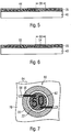
Fig. 2 entlang der Linie V-V, - Fig. 6
- eine Darstellung wie in
Fig. 5 für ein nicht beanspruchtes Ausführungsbeispiel, bei dem die Interferenzschichtpigmente durch die Laserstrahlung orientierungserhaltend modifiziert sind, und - Fig. 7
- ein erfindungsgemäßes Sicherheitselement, bei dem das lasergenerierte statische Motiv passergenau in den Umgebungsbereich der Farbschicht weitergeführt ist.
- Fig. 1
- a schematic representation of a banknote with a security element according to the invention,
- Fig. 2
- a view of the security element of
Fig. 1 . - Fig. 3
- schematically the orientation of the still movable magnetic pigments of a security element according to the invention in the field of a spherical magnet,
- Fig. 4
- a cross section through the security element of
Fig. 2 along the line IV-IV, - Fig. 5
- a cross section through the security element of
Fig. 2 along the line VV, - Fig. 6
- a representation like in
Fig. 5 for a non-claimed embodiment in which the interference layer pigments are modified by the laser radiation preservation, and - Fig. 7
- a security element according to the invention, in which the laser-generated static motif is continued in register with the surrounding area of the color layer.
Die Erfindung wird nun am Beispiel von Sicherheitselementen für Banknoten erläutert.
Mit Bezug auf
Das dynamische Motiv 22 ist mit einem lasergenerierten, statischen Motiv 28 in Form zweier Achtelnoten kombiniert, das keinen Bewegungseffekt zeigt, sondern bei der Betrachtung einen ortsfesten Bezugspunkt für das dynamische Motiv 22 bildet.The
Durch diesen, in das Sicherheitselement integrierten, festen Bezugpunkt des statischen Motivs 28 werden der dynamische Bewegungseffekt und das dreidimensional anmutende Erscheinungsbild der ausgerichteten Magnetpigmente betont und dadurch noch deutlicher. Die unmittelbare Nähe des ortfesten Motivs 28 lenkt die Aufmerksamkeit des Betrachters durch die Kontrastwirkung verstärkt auf das sich scheinbar bewegende dynamische Motiv 22.This fixed reference point of the
Der Betrachter kann das Sicherheitselement 12 auch leicht auf Echtheit überprüfen, da die Kombination aus statischem und dynamischem Motiv einfach zu memorieren und ihr Vorliegen ohne Hilfsmittel festzustellen ist.The viewer can also easily check the
Schließlich lassen sich, wie nachfolgend genauer ausgeführt, durch die Erzeugung des statischen Motivs mittels Laserstrahlung besondere Effekte in der Kombinationskennzeichnung erzeugen, die auf andere Weise nicht oder nur schwer erzielt werden können.Finally, as explained in more detail below, the generation of the static motif by means of laser radiation can produce special effects in the combination marking which can not or only with difficulty be achieved in other ways.
Mit Bezug auf die
Bei den Magnetpigmenten 44 kann es sich beispielsweise um plättchenförmige Eisenpigmente handeln, die aus reduzierend behandeltem Carbonyleisenpulver hergestellt sind und die mit einem hohen Verhältnis von Plättchendurchmesser zu Plättchendicke erzeugt werden können. Ebenfalls in Betracht kommen nasschemisch hergestellte Pigmente mit einem Träger aus Mica, SiO2 oder Glimmer und einer Außenhülle aus Eisenoxid (Fe3O4), die den Magnetpigmenten ihre magnetischen Eigenschaften verleiht. Derartige Pigmente werden beispielsweise von der Merck KGaA unter der Bezeichnung Colorona Blackstar(R) angeboten. Durch Veränderung der Eisenoxid-Schichtdicke können hier unterschiedliche Farbtöne erzielt werden (z. B. grün, blau, rot). Für den Sicherheitsdruck sind auch deckende magnetische Pigmente mit Farbkippeffekt, beispielsweise unter der Bezeichnung Colorcrypt(R) Magnetic Gold, magnetische Interferenzpigmente, wie sie in der
Im Ausführungsbeispiel wird zur Herstellung des Sicherheitselements 12 auf ein Substrat 40 eine Farbschicht 20 auf Basis eines UV-härtenden Farbsystems aufgebracht, die die gewünschten magnetisch ausrichtbaren, plättchenförmigen Magnetpigmente 44 enthält. Das Aufdrucken der Farbschicht 20 erfolgt dabei vorzugsweise im Siebdruck.In the exemplary embodiment, to produce the
Dann wird das Substrat 40 mit den in der Farbschicht 20 noch beweglichen Magnetpigmenten 44 in geringem Abstand über einen Kugelmagneten 30 gebracht (
Auf diese Weise entsteht eine zentrosymmetrische, kreisförmige Kennzeichnung 22, die in ihrem Inneren einen im Wesentlichen einheitlich ausgerichteten Bereich 24 (
Nach der Ausrichtung und Fixierung der Magnetpigmente 44 wird die Farbschicht 20 mit Laserstrahlung, vorzugsweise Laserstrahlung eines gepulsten Infrarotlasers mit kurzen Pulsdauern von etwa 20 ns oder weniger, vorzugsweise von etwa 12 ns oder weniger, beaufschlagt. Der Laserstrahl wird dabei typischerweise mit einer Breite von einigen Zehntel Millimetern und einer Markierungsgeschwindigkeit von einigen m/s in Form des gewünschten statischen Motivs 28 über die Farbschicht 20 geführt.After the alignment and fixing of the
Durch die Laserstrahlung wird in den beaufschlagten Bereichen die Orientierung der Magnetpigmente zerstört oder die Magnetpigmente 44 werden in den beaufschlagten Bereichen 28 sogar vollständig aus der Farbschicht 20 entfernt. Letzteres ist in
Auch der visuelle Eindruck der Farbschicht 20 ist in den beaufschlagten Bereichen 28 gegenüber den nicht beaufschlagten Bereichen der Farbschicht verändert, wobei die Art der visuellen Änderung insbesondere durch die Auslegung der Farbschicht, durch die Wahl der Magnetpigmente, durch die Laserparameter bei der Beaufschlagung, durch eine gegebenenfalls unterhalb des Farbschicht 20 angeordnete Untergrundschicht oder eine über der Farbschicht 20 angeordnete Deckschicht in weiten Bereichen nach Wunsch eingestellt werden kann.The visual impression of the
Beispielsweise kann die Farbschicht 20 zusätzlich zu den Magnetpigmenten 44 Farbpigmente enthalten, die von der Laserstrahlung nicht beeinflusst werden und deren Farbeindruck nach der Beaufschlagung den visuellen Eindruck der Bereiche 28 bestimmt. Die Farbschicht 20 kann nach dem Entfernen der Magnetpigmente auch transparent oder transluzent sein und in den Bereichen 28 den Blick auf eine Untergrundschicht freigeben. Eine solche Untergrundschicht kann einfarbig sein oder selbst eine Kennzeichnung enthalten, so dass die beaufschlagen Bereiche 28 an unterschiedlichen Stellen des Sicherheitselements 12 einen unterschiedlichen visuellen Eindruck zeigen.For example, in addition to the
In einer anderen Ausgestaltung wird durch die Laserstrahlung die Ausrichtung der Magnetpigmente erhalten, jedoch werden die optischen Eigenschaften, insbesondere die Farbe oder die optische Variabilität der Magnetpigmente verändert.In another embodiment, the alignment of the magnetic pigments is obtained by the laser radiation, however, the optical properties, in particular the color or the optical variability of the magnetic pigments are changed.
Durch die orientierungserhaltende Modifikation der optischen Eigenschaften der Magnetpigmente 52 entsteht in dem Sicherheitselement ein Mischbereich, in dem die modifizierten Pigmente 54 durch ihre erhaltene Orientierung einerseits ein dreidimensional anmutendes Erscheinungsbild zeigen. Andererseits wird durch den ortsfesten Umriss der Bereiche 50 eine statische Information in die Farbschicht 20 eingebracht, die als fester Bezugspunkt für das dynamische Motiv 22 dient. Insbesondere bleiben hierbei die dynamischen Hell-Dunkel-Effekte der modifizierten Magnetpigmente 54 unverändert, so dass der Eindruck einer festen Ebene über dem dynamischen Motiv 22 entsteht, durch die das dynamischen Motiv 22 gleichsam durchscheint.As a result of the orientation-preserving modification of the optical properties of the
Die orientierungserhaltende Modifikation der optischen Eigenschaften der Magnetpigmente 52 kann als zusätzliches Sicherheitsmerkmal eingesetzt werden, da die unveränderte Ausrichtung der modifizierten Pigmente 54 sowohl durch den Erhalt der Hell-Dunkel-Effekte visuell als auch mit geeigneten Hilfsmitteln noch betrachtet und nachgewiesen werden kann.The orientation-preserving modification of the optical properties of the
Die Fälschungssicherheit erfindungsgemäßer Sicherheitselemente lässt sich auch dadurch weiter erhöhen, dass das lasergenerierte statische Motiv passergenau in den Umgebungsbereich der Farbschicht 20 weitergeführt wird.
Alternativ oder zusätzlich zu den Farbpigmenten kann das Farbgemisch auch optisch variable Pigmente, insbesondere Interferenzpigmente oder Flüssigkristallpigmente enthalten. Ferner kann das Farbgemisch aus einer Mischung verschiedener magnetisch ausgerichteter plättchenförmiger Magnetpigmente bestehen.Alternatively or in addition to the color pigments, the color mixture may also contain optically variable pigments, in particular interference pigments or liquid crystal pigments. Furthermore, the color mixture may consist of a mixture of different magnetically oriented platelet-shaped magnetic pigments.
Das dynamische Motiv 22 ist mit zwei lasergenerierten statischen Motiven 62, 64 kombiniert, die ortsfeste Bezugspunkte für das dynamische Motiv 22 bilden. Das erste statische Motiv 62 bildet durch seinen Umriss die Denomination "50" der Banknote 10 und ist durch einen Bereich gebildet, in dem die optischen Eigenschaften der Magnetpigmente orientierungserhaltend modifiziert wurden. Die Ziffern der Denomination "50" erscheinen mit ihrem ortsfesten Umriss beispielsweise silbern vor dem farbkippenden, gelbgrüngrundierten Hintergrund der optisch variablen Magnetpigmente und der gelbgrünen Farbpigmente der Farbschicht 20.The
Das zweite, linienförmige, statische Motiv 64 erstreckt sich über die Grenze der Farbschicht 20 hinaus in das angrenzende Banknotensubstrat 70. In dem Teilbereich 66 des Motivs, der sich innerhalb der Farbschicht 20 befindet, sind durch die Laserbeaufschlagung die Magnetpigmente vollständig aus der Farbschicht 20 entfernt, wie in
In dem sich in das Banknotensubstrat 70 erstreckenden Teilbereich 68 des zweiten Motivs 64 wird durch die Einwirkung der Laserstrahlung eine gefärbte und taktil erfassbare Markierung im Banknotensubstrat 70 erzeugt. Da die Teilbereiche 66, 68 innerhalb und außerhalb der Farbschicht 20 durch eine kontinuierliche Führung desselben Laserstrahls erzeugt werden, stehen sie in perfektem Passer zueinander. Das Sicherheitselement 60 wird durch das über den Rand der Farbschicht 20 hinausgreifende statische Motiv 64 mit dem umgebenden Banknotensubstrat 70 praktisch "vernäht".In the
Ein solches durchgehendes Motiv zwischen einer Siebdruckfarbschicht 20 und dem umgebenden Substrat mit Farbkante am Rand des Elements lässt sich mit perfekter Passerung nur durch die erfindungsgemäße Laserbeaufschlagung erreichen. Ein weiterer Sicherheitseffekt ist bei dem beschriebenen Ausführungsbeispiel durch die gelbgrüne Farbe des innerhalb der Farbschicht angeordneten Teilbereichs 66 gebildet, die durch die Entfernung der Magnetpigmente und das Stehenbleiben der gelbgrünen Farbpigmente entsteht. Die Farbe des Teilbereichs 66 entspricht daher der Farbgrundierung der umgebenden, farbkippenden Schicht 20. Eine solche Entsprechung lässt sich drucktechnisch nur sehr schwer nachstellen, insbesondere nicht zusammen mit der perfekten Passerung der fortgeführten Teilbereiche 66, 68.Such a continuous motif between a screen-
- 1010
- Banknotebill
- 1212
- Sicherheitselementsecurity element
- 2020
- Farbschichtcoat of paint
- 2121
- Umgebungsbereichsurrounding area
- 2222
- Kennzeichnung, dynamisches MotivMarking, dynamic motif
- 2424
- innerer Bereichinner area
- 2626
- ÜbergangsbereichTransition area
- 2828
- statisches Motivstatic motive
- 3030
- Kugelmagnetbullet magnet
- 3232
- Feldlinienfield lines
- 4040
- Substratsubstratum
- 4242
- BereichArea
- 4444
- Magnetpigmentemagnetic pigments
- 5050
- beaufschlagter Bereichacted upon area
- 5252
- magnetische Interferenzschichtpigmentemagnetic interference layer pigments
- 5454
- modifizierte Pigmentemodified pigments
- 6060
- Sicherheitselementsecurity element
- 62, 6462, 64
- statische Motivestatic motives
- 66, 6866, 68
- Teilbereichesubregions
- 7070
- BanknotensubstratBanknote substrate
Claims (15)
- A security element (12) for security papers, value documents and other data carriers, having at least one ink layer (20) having magnetically aligned and in their alignment fixed magnetic pigments (44) that form, in the form of patterns, characters or a code, a first motif (22) that displays a dynamic motion effect when the security element is tilted, wherein the first, dynamic motif (22) is combined with, in the form of patterns, characters or a code, a second, static motif (28) that is produced by the action of laser radiation in the ink layer and whose fixed contour, when viewed, forms a fixed reference point for the dynamic motif, characterized in that in the region of the second, static motif (28), the orientation of the magnetic pigments (44) is destroyed, or in that, in the region of the second, static motif (28), the magnetic pigments are removed from the ink layer (20), wherein the aligned pigments (44) form a three-dimensional-seeming appearance.
- The security element according to claim 1, characterized in that the magnetic pigments are developed to be non-spherical, especially platelet-shaped.
- The security element according to claim 1 or 2, characterized in that the magnetic pigments are dyed and/or optically variable, especially include color-shifting thin-film elements having an interference layer structure.
- The security element according to at least one of claims 1 to 3, characterized in that the magnetic pigments are formed on the basis of ultra-pure iron powder.
- The security element according to at least one of claims 1 to 4, characterized in that the magnetic pigments are aligned in the form of a centrosymmetric marking that preferably includes, in its interior, a substantially uniformly aligned region having a diameter of 5 mm or more, and/or that the magnetic pigments are aligned by a sphere magnet or by multiple spaced-apart sphere magnets in the form of the first motif.
- The security element according to at least one of claims 1 to 5, characterized in that the second, static motif is arranged completely within the ink layer having the aligned magnetic pigments, or that the second, static motif is arranged in register partially within and partially outside the ink layer having the aligned magnetic pigments.
- The security element according to at least one of claims 1 to 6, characterized in that, the ink layer is formed by a screen printing layer, and/or that the ink layer having the magnetic pigments is formed on the basis of a UV-curing ink system.
- The security element according to at least one of claims 1 to 7, characterized in that the ink layer includes, in addition to the magnetically aligned magnetic pigments, dyes, luminescent substances or further pigments, especially colored pigments and/or luminescent pigments and/or optically variable pigments.
- The security element according to at least one of claims 1 to 8, characterized in that the ink layer is arranged on a background layer that is colored or optically variable, especially in that the background layer exhibits a colored or optically variable further marking.
- A method for manufacturing a security element (12) for safeguarding security papers, value documents and other data carriers, in which- at least one ink (20) layer having magnetically alignable magnetic pigments is applied to a substrate,- the magnetic pigments (44) are magnetically aligned in the form of patterns, characters or a code and are fixed in their orientation, thus producing a first motif (22) having a dynamic motion effect and a three-dimensional-seeming appearance, and- through laser impingement in the ink layer, a second, static motif (28) in the form of patterns, characters or a code is produced whose fixed contour, when viewed, forms a fixed reference point for the first motif, wherein in the region of the second, static motif (28), the orientation of the magnetic pigments (44) is destroyed, or in that, in the region of the second, static motif (28), the magnetic pigments are removed from the ink layer (20).
- The method according to claim 10, characterized in that an ink layer on the basis of a UV-curing ink system is used and the aligned magnetic pigments are fixed by UV-curing the ink layer.
- The method according to claim 10 or 11, characterized in that the ink layer is printed in screen printing.
- The method according to at least one of claims 10 to 12, characterized in that the laser impingement is carried out with a pulsed infrared laser in the wavelength range from 0.8 µm to 3 µm, preferably with short pulse durations of 20 ns or less, particularly preferably with short pulse durations of 12 ns or less.
- A data carrier (12) having a security element according to at least one of claims 1 to 9.
- The data carrier according to claim 14, characterized in that the security element is arranged in or over a transparent window region or a through opening in the data carrier.
Priority Applications (1)
| Application Number | Priority Date | Filing Date | Title |
|---|---|---|---|
| PL11706491T PL2542421T3 (en) | 2010-03-03 | 2011-03-02 | Security element having aligned magnetic pigments |
Applications Claiming Priority (2)
| Application Number | Priority Date | Filing Date | Title |
|---|---|---|---|
| DE102010009977A DE102010009977A1 (en) | 2010-03-03 | 2010-03-03 | Security element with aligned magnetic pigments |
| PCT/EP2011/001031 WO2011107271A1 (en) | 2010-03-03 | 2011-03-02 | Security element having aligned magnetic pigments |
Publications (2)
| Publication Number | Publication Date |
|---|---|
| EP2542421A1 EP2542421A1 (en) | 2013-01-09 |
| EP2542421B1 true EP2542421B1 (en) | 2019-05-08 |
Family
ID=44045282
Family Applications (1)
| Application Number | Title | Priority Date | Filing Date |
|---|---|---|---|
| EP11706491.5A Active EP2542421B1 (en) | 2010-03-03 | 2011-03-02 | Security element having aligned magnetic pigments |
Country Status (7)
| Country | Link |
|---|---|
| EP (1) | EP2542421B1 (en) |
| AU (1) | AU2011223202A1 (en) |
| BR (1) | BR112012021113A2 (en) |
| CA (1) | CA2791199A1 (en) |
| DE (1) | DE102010009977A1 (en) |
| PL (1) | PL2542421T3 (en) |
| WO (1) | WO2011107271A1 (en) |
Cited By (4)
| Publication number | Priority date | Publication date | Assignee | Title |
|---|---|---|---|---|
| WO2021259527A1 (en) | 2020-06-23 | 2021-12-30 | Sicpa Holding Sa | Methods for producing optical effect layers comprising magnetic or magnetizable pigment particles |
| WO2022207692A1 (en) | 2021-03-31 | 2022-10-06 | Sicpa Holding Sa | Methods for producing optical effect layers comprising magnetic or magnetizable pigment particles and exhibiting one or more indicia |
| WO2023161464A1 (en) | 2022-02-28 | 2023-08-31 | Sicpa Holding Sa | Methods for producing optical effect layers comprising magnetic or magnetizable pigment particles and exhibiting one or more indicia |
| WO2024028408A1 (en) | 2022-08-05 | 2024-02-08 | Sicpa Holding Sa | Methods for producing optical effect layers comprising magnetic or magnetizable pigment particles and exhibiting one or more indicia |
Families Citing this family (12)
| Publication number | Priority date | Publication date | Assignee | Title |
|---|---|---|---|---|
| DE102011116494A1 (en) * | 2011-10-20 | 2013-04-25 | Giesecke & Devrient Gmbh | Method for producing an optically variable security element with microcapsule-based ink layer |
| DE102011120848B3 (en) * | 2011-12-09 | 2013-05-23 | Giesecke & Devrient Gmbh | Security element for valuable objects e.g. chipcard, has plastic substrate comprising color layer that is embedded with magnetic particle, where portion of particle is arranged proximity of limiting surface between covering and color layers |
| DE102012006623A1 (en) | 2012-03-30 | 2013-10-02 | Giesecke & Devrient Gmbh | Method for producing a data carrier and data carrier available therefrom |
| MA39097B1 (en) * | 2013-12-13 | 2018-08-31 | Sicpa Holding Sa | Method for producing optical effect layers |
| DE102014004347A1 (en) | 2014-03-27 | 2015-10-15 | Friedrich Kisters | Authentication method and authentication system |
| DE102014004349A1 (en) | 2014-03-27 | 2015-10-15 | Friedrich Kisters | authentication system |
| DE102014004348A1 (en) | 2014-03-27 | 2015-10-15 | Friedrich Kisters | security procedures |
| ES2633025T3 (en) | 2014-05-23 | 2017-09-18 | Merck Patent Gmbh | Procedure for laser treatment of coatings |
| DE102014007976A1 (en) | 2014-06-04 | 2015-12-31 | Friedrich Kisters | Security device and authentication method with dynamic security features |
| US10357991B2 (en) | 2016-12-19 | 2019-07-23 | Viavi Solutions Inc. | Security ink based security feature |
| DE102018000385A1 (en) * | 2018-01-18 | 2019-07-18 | Giesecke+Devrient Currency Technology Gmbh | Setting magnet for the production of security elements with magnetically oriented effect pigments and production method for such setting magnets |
| CN114031306B (en) * | 2020-07-21 | 2023-03-28 | 杭州玻美文化艺术有限公司 | Colorful solar glass panel and manufacturing method thereof |
Family Cites Families (7)
| Publication number | Priority date | Publication date | Assignee | Title |
|---|---|---|---|---|
| DE4439455A1 (en) * | 1994-11-04 | 1996-05-09 | Basf Ag | Process for the production of coatings with three-dimensional optical effects |
| US7047883B2 (en) | 2002-07-15 | 2006-05-23 | Jds Uniphase Corporation | Method and apparatus for orienting magnetic flakes |
| EP1239307A1 (en) | 2001-03-09 | 2002-09-11 | Sicpa Holding S.A. | Magnetic thin film interference device |
| DE10114446A1 (en) | 2001-03-23 | 2002-09-26 | Eckart Standard Bronzepulver | Flat iron pigment used paints, plastics, printing, glass, ceramics and cosmetics comprises reduced carbonyl iron powder |
| DE102004004713A1 (en) * | 2004-01-30 | 2005-09-01 | Leonhard Kurz Gmbh & Co. Kg | Security element with partial magnetic layer |
| DE102007043052A1 (en) | 2007-09-11 | 2009-03-12 | Giesecke & Devrient Gmbh | Optically variable security element |
| DE102007059550A1 (en) * | 2007-12-11 | 2009-06-25 | Giesecke & Devrient Gmbh | Optically variable security element |
-
2010
- 2010-03-03 DE DE102010009977A patent/DE102010009977A1/en not_active Withdrawn
-
2011
- 2011-03-02 PL PL11706491T patent/PL2542421T3/en unknown
- 2011-03-02 CA CA2791199A patent/CA2791199A1/en not_active Abandoned
- 2011-03-02 BR BR112012021113A patent/BR112012021113A2/en not_active IP Right Cessation
- 2011-03-02 AU AU2011223202A patent/AU2011223202A1/en not_active Abandoned
- 2011-03-02 EP EP11706491.5A patent/EP2542421B1/en active Active
- 2011-03-02 WO PCT/EP2011/001031 patent/WO2011107271A1/en active Application Filing
Non-Patent Citations (1)
| Title |
|---|
| None * |
Cited By (4)
| Publication number | Priority date | Publication date | Assignee | Title |
|---|---|---|---|---|
| WO2021259527A1 (en) | 2020-06-23 | 2021-12-30 | Sicpa Holding Sa | Methods for producing optical effect layers comprising magnetic or magnetizable pigment particles |
| WO2022207692A1 (en) | 2021-03-31 | 2022-10-06 | Sicpa Holding Sa | Methods for producing optical effect layers comprising magnetic or magnetizable pigment particles and exhibiting one or more indicia |
| WO2023161464A1 (en) | 2022-02-28 | 2023-08-31 | Sicpa Holding Sa | Methods for producing optical effect layers comprising magnetic or magnetizable pigment particles and exhibiting one or more indicia |
| WO2024028408A1 (en) | 2022-08-05 | 2024-02-08 | Sicpa Holding Sa | Methods for producing optical effect layers comprising magnetic or magnetizable pigment particles and exhibiting one or more indicia |
Also Published As
| Publication number | Publication date |
|---|---|
| AU2011223202A1 (en) | 2012-10-25 |
| WO2011107271A1 (en) | 2011-09-09 |
| EP2542421A1 (en) | 2013-01-09 |
| PL2542421T3 (en) | 2019-11-29 |
| DE102010009977A1 (en) | 2011-09-08 |
| CA2791199A1 (en) | 2011-09-09 |
| BR112012021113A2 (en) | 2019-09-24 |
Similar Documents
| Publication | Publication Date | Title |
|---|---|---|
| EP2542421B1 (en) | Security element having aligned magnetic pigments | |
| EP2608964B1 (en) | Security element comprising oriented magnetic pigments | |
| EP2273455B1 (en) | Security element | |
| EP2121348B1 (en) | Security element for a valuable document | |
| EP2643161B1 (en) | Document of value and/or security document with coloured transparent security feature and method for producing the same | |
| DE102007059550A1 (en) | Optically variable security element | |
| EP1810253A1 (en) | Optically variable security element | |
| WO2015078572A1 (en) | Security element comprising magnetically alignable magnetic pigments and a second motif, and method for producing same | |
| DE102007043052A1 (en) | Optically variable security element | |
| WO2016155859A1 (en) | Security element with effect pigments and an embossing structure and method for the production thereof | |
| EP2734383A1 (en) | Microcapsule and use thereof, security element having microcapsules and data carrier equipped therewith | |
| DE102011116494A1 (en) | Method for producing an optically variable security element with microcapsule-based ink layer | |
| EP2768677B1 (en) | Optically variable security element with an ink layer based on microcapsules and process for producing the same | |
| WO2014086495A1 (en) | Optically variable security element with optically variable coloured layer structure | |
| EP2723577B1 (en) | Magnetic screen printing ink or flexographic ink and security element printed using the same | |
| EP2694297B1 (en) | Data carrier with security element and process to manufacture the data carrier | |
| DE102016004238A1 (en) | Security document with inspection window | |
| EP3960481B1 (en) | Optically variable security element | |
| EP4342683A1 (en) | Security element with a machineable code and method for producing a security element | |
| EP2868483A1 (en) | Method for making a security element | |
| EP4342682A1 (en) | Security element comprising a machine-readable code and method for producing same | |
| EP3954543A1 (en) | Optically variable security element |
Legal Events
| Date | Code | Title | Description |
|---|---|---|---|
| PUAI | Public reference made under article 153(3) epc to a published international application that has entered the european phase |
Free format text: ORIGINAL CODE: 0009012 |
|
| 17P | Request for examination filed |
Effective date: 20121004 |
|
| AK | Designated contracting states |
Kind code of ref document: A1 Designated state(s): AL AT BE BG CH CY CZ DE DK EE ES FI FR GB GR HR HU IE IS IT LI LT LU LV MC MK MT NL NO PL PT RO RS SE SI SK SM TR |
|
| DAX | Request for extension of the european patent (deleted) | ||
| 17Q | First examination report despatched |
Effective date: 20141106 |
|
| STAA | Information on the status of an ep patent application or granted ep patent |
Free format text: STATUS: EXAMINATION IS IN PROGRESS |
|
| RAP1 | Party data changed (applicant data changed or rights of an application transferred) |
Owner name: GIESECKE+DEVRIENT CURRENCY TECHNOLOGY GMBH |
|
| GRAP | Despatch of communication of intention to grant a patent |
Free format text: ORIGINAL CODE: EPIDOSNIGR1 |
|
| STAA | Information on the status of an ep patent application or granted ep patent |
Free format text: STATUS: GRANT OF PATENT IS INTENDED |
|
| INTG | Intention to grant announced |
Effective date: 20181206 |
|
| GRAS | Grant fee paid |
Free format text: ORIGINAL CODE: EPIDOSNIGR3 |
|
| GRAA | (expected) grant |
Free format text: ORIGINAL CODE: 0009210 |
|
| STAA | Information on the status of an ep patent application or granted ep patent |
Free format text: STATUS: THE PATENT HAS BEEN GRANTED |
|
| AK | Designated contracting states |
Kind code of ref document: B1 Designated state(s): AL AT BE BG CH CY CZ DE DK EE ES FI FR GB GR HR HU IE IS IT LI LT LU LV MC MK MT NL NO PL PT RO RS SE SI SK SM TR |
|
| REG | Reference to a national code |
Ref country code: GB Ref legal event code: FG4D Free format text: NOT ENGLISH |
|
| REG | Reference to a national code |
Ref country code: CH Ref legal event code: EP Ref country code: AT Ref legal event code: REF Ref document number: 1129548 Country of ref document: AT Kind code of ref document: T Effective date: 20190515 |
|
| REG | Reference to a national code |
Ref country code: DE Ref legal event code: R096 Ref document number: 502011015680 Country of ref document: DE Ref country code: IE Ref legal event code: FG4D Free format text: LANGUAGE OF EP DOCUMENT: GERMAN |
|
| REG | Reference to a national code |
Ref country code: NL Ref legal event code: MP Effective date: 20190508 |
|
| REG | Reference to a national code |
Ref country code: LT Ref legal event code: MG4D |
|
| PG25 | Lapsed in a contracting state [announced via postgrant information from national office to epo] |
Ref country code: LT Free format text: LAPSE BECAUSE OF FAILURE TO SUBMIT A TRANSLATION OF THE DESCRIPTION OR TO PAY THE FEE WITHIN THE PRESCRIBED TIME-LIMIT Effective date: 20190508 Ref country code: HR Free format text: LAPSE BECAUSE OF FAILURE TO SUBMIT A TRANSLATION OF THE DESCRIPTION OR TO PAY THE FEE WITHIN THE PRESCRIBED TIME-LIMIT Effective date: 20190508 Ref country code: NL Free format text: LAPSE BECAUSE OF FAILURE TO SUBMIT A TRANSLATION OF THE DESCRIPTION OR TO PAY THE FEE WITHIN THE PRESCRIBED TIME-LIMIT Effective date: 20190508 Ref country code: NO Free format text: LAPSE BECAUSE OF FAILURE TO SUBMIT A TRANSLATION OF THE DESCRIPTION OR TO PAY THE FEE WITHIN THE PRESCRIBED TIME-LIMIT Effective date: 20190808 Ref country code: SE Free format text: LAPSE BECAUSE OF FAILURE TO SUBMIT A TRANSLATION OF THE DESCRIPTION OR TO PAY THE FEE WITHIN THE PRESCRIBED TIME-LIMIT Effective date: 20190508 Ref country code: FI Free format text: LAPSE BECAUSE OF FAILURE TO SUBMIT A TRANSLATION OF THE DESCRIPTION OR TO PAY THE FEE WITHIN THE PRESCRIBED TIME-LIMIT Effective date: 20190508 Ref country code: AL Free format text: LAPSE BECAUSE OF FAILURE TO SUBMIT A TRANSLATION OF THE DESCRIPTION OR TO PAY THE FEE WITHIN THE PRESCRIBED TIME-LIMIT Effective date: 20190508 Ref country code: PT Free format text: LAPSE BECAUSE OF FAILURE TO SUBMIT A TRANSLATION OF THE DESCRIPTION OR TO PAY THE FEE WITHIN THE PRESCRIBED TIME-LIMIT Effective date: 20190908 Ref country code: ES Free format text: LAPSE BECAUSE OF FAILURE TO SUBMIT A TRANSLATION OF THE DESCRIPTION OR TO PAY THE FEE WITHIN THE PRESCRIBED TIME-LIMIT Effective date: 20190508 |
|
| PG25 | Lapsed in a contracting state [announced via postgrant information from national office to epo] |
Ref country code: BG Free format text: LAPSE BECAUSE OF FAILURE TO SUBMIT A TRANSLATION OF THE DESCRIPTION OR TO PAY THE FEE WITHIN THE PRESCRIBED TIME-LIMIT Effective date: 20190808 Ref country code: GR Free format text: LAPSE BECAUSE OF FAILURE TO SUBMIT A TRANSLATION OF THE DESCRIPTION OR TO PAY THE FEE WITHIN THE PRESCRIBED TIME-LIMIT Effective date: 20190809 Ref country code: LV Free format text: LAPSE BECAUSE OF FAILURE TO SUBMIT A TRANSLATION OF THE DESCRIPTION OR TO PAY THE FEE WITHIN THE PRESCRIBED TIME-LIMIT Effective date: 20190508 Ref country code: RS Free format text: LAPSE BECAUSE OF FAILURE TO SUBMIT A TRANSLATION OF THE DESCRIPTION OR TO PAY THE FEE WITHIN THE PRESCRIBED TIME-LIMIT Effective date: 20190508 |
|
| PG25 | Lapsed in a contracting state [announced via postgrant information from national office to epo] |
Ref country code: EE Free format text: LAPSE BECAUSE OF FAILURE TO SUBMIT A TRANSLATION OF THE DESCRIPTION OR TO PAY THE FEE WITHIN THE PRESCRIBED TIME-LIMIT Effective date: 20190508 Ref country code: DK Free format text: LAPSE BECAUSE OF FAILURE TO SUBMIT A TRANSLATION OF THE DESCRIPTION OR TO PAY THE FEE WITHIN THE PRESCRIBED TIME-LIMIT Effective date: 20190508 Ref country code: RO Free format text: LAPSE BECAUSE OF FAILURE TO SUBMIT A TRANSLATION OF THE DESCRIPTION OR TO PAY THE FEE WITHIN THE PRESCRIBED TIME-LIMIT Effective date: 20190508 Ref country code: CZ Free format text: LAPSE BECAUSE OF FAILURE TO SUBMIT A TRANSLATION OF THE DESCRIPTION OR TO PAY THE FEE WITHIN THE PRESCRIBED TIME-LIMIT Effective date: 20190508 Ref country code: SK Free format text: LAPSE BECAUSE OF FAILURE TO SUBMIT A TRANSLATION OF THE DESCRIPTION OR TO PAY THE FEE WITHIN THE PRESCRIBED TIME-LIMIT Effective date: 20190508 |
|
| REG | Reference to a national code |
Ref country code: DE Ref legal event code: R097 Ref document number: 502011015680 Country of ref document: DE |
|
| PG25 | Lapsed in a contracting state [announced via postgrant information from national office to epo] |
Ref country code: SM Free format text: LAPSE BECAUSE OF FAILURE TO SUBMIT A TRANSLATION OF THE DESCRIPTION OR TO PAY THE FEE WITHIN THE PRESCRIBED TIME-LIMIT Effective date: 20190508 Ref country code: IT Free format text: LAPSE BECAUSE OF FAILURE TO SUBMIT A TRANSLATION OF THE DESCRIPTION OR TO PAY THE FEE WITHIN THE PRESCRIBED TIME-LIMIT Effective date: 20190508 |
|
| PLBE | No opposition filed within time limit |
Free format text: ORIGINAL CODE: 0009261 |
|
| STAA | Information on the status of an ep patent application or granted ep patent |
Free format text: STATUS: NO OPPOSITION FILED WITHIN TIME LIMIT |
|
| PG25 | Lapsed in a contracting state [announced via postgrant information from national office to epo] |
Ref country code: TR Free format text: LAPSE BECAUSE OF FAILURE TO SUBMIT A TRANSLATION OF THE DESCRIPTION OR TO PAY THE FEE WITHIN THE PRESCRIBED TIME-LIMIT Effective date: 20190508 |
|
| 26N | No opposition filed |
Effective date: 20200211 |
|
| PG25 | Lapsed in a contracting state [announced via postgrant information from national office to epo] |
Ref country code: SI Free format text: LAPSE BECAUSE OF FAILURE TO SUBMIT A TRANSLATION OF THE DESCRIPTION OR TO PAY THE FEE WITHIN THE PRESCRIBED TIME-LIMIT Effective date: 20190508 |
|
| REG | Reference to a national code |
Ref country code: DE Ref legal event code: R119 Ref document number: 502011015680 Country of ref document: DE |
|
| PG25 | Lapsed in a contracting state [announced via postgrant information from national office to epo] |
Ref country code: MC Free format text: LAPSE BECAUSE OF FAILURE TO SUBMIT A TRANSLATION OF THE DESCRIPTION OR TO PAY THE FEE WITHIN THE PRESCRIBED TIME-LIMIT Effective date: 20190508 |
|
| REG | Reference to a national code |
Ref country code: CH Ref legal event code: PL |
|
| REG | Reference to a national code |
Ref country code: BE Ref legal event code: MM Effective date: 20200331 |
|
| PG25 | Lapsed in a contracting state [announced via postgrant information from national office to epo] |
Ref country code: LU Free format text: LAPSE BECAUSE OF NON-PAYMENT OF DUE FEES Effective date: 20200302 |
|
| PG25 | Lapsed in a contracting state [announced via postgrant information from national office to epo] |
Ref country code: FR Free format text: LAPSE BECAUSE OF NON-PAYMENT OF DUE FEES Effective date: 20200331 Ref country code: CH Free format text: LAPSE BECAUSE OF NON-PAYMENT OF DUE FEES Effective date: 20200331 Ref country code: DE Free format text: LAPSE BECAUSE OF NON-PAYMENT OF DUE FEES Effective date: 20201001 Ref country code: LI Free format text: LAPSE BECAUSE OF NON-PAYMENT OF DUE FEES Effective date: 20200331 Ref country code: IE Free format text: LAPSE BECAUSE OF NON-PAYMENT OF DUE FEES Effective date: 20200302 |
|
| PG25 | Lapsed in a contracting state [announced via postgrant information from national office to epo] |
Ref country code: BE Free format text: LAPSE BECAUSE OF NON-PAYMENT OF DUE FEES Effective date: 20200331 |
|
| GBPC | Gb: european patent ceased through non-payment of renewal fee |
Effective date: 20200302 |
|
| PG25 | Lapsed in a contracting state [announced via postgrant information from national office to epo] |
Ref country code: GB Free format text: LAPSE BECAUSE OF NON-PAYMENT OF DUE FEES Effective date: 20200302 |
|
| REG | Reference to a national code |
Ref country code: AT Ref legal event code: MM01 Ref document number: 1129548 Country of ref document: AT Kind code of ref document: T Effective date: 20200302 |
|
| PG25 | Lapsed in a contracting state [announced via postgrant information from national office to epo] |
Ref country code: AT Free format text: LAPSE BECAUSE OF NON-PAYMENT OF DUE FEES Effective date: 20200302 |
|
| PG25 | Lapsed in a contracting state [announced via postgrant information from national office to epo] |
Ref country code: PL Free format text: LAPSE BECAUSE OF NON-PAYMENT OF DUE FEES Effective date: 20200302 Ref country code: CY Free format text: LAPSE BECAUSE OF FAILURE TO SUBMIT A TRANSLATION OF THE DESCRIPTION OR TO PAY THE FEE WITHIN THE PRESCRIBED TIME-LIMIT Effective date: 20190508 |
|
| PG25 | Lapsed in a contracting state [announced via postgrant information from national office to epo] |
Ref country code: MT Free format text: LAPSE BECAUSE OF NON-PAYMENT OF DUE FEES Effective date: 20200302 Ref country code: MK Free format text: LAPSE BECAUSE OF FAILURE TO SUBMIT A TRANSLATION OF THE DESCRIPTION OR TO PAY THE FEE WITHIN THE PRESCRIBED TIME-LIMIT Effective date: 20190508 Ref country code: IS Free format text: LAPSE BECAUSE OF FAILURE TO SUBMIT A TRANSLATION OF THE DESCRIPTION OR TO PAY THE FEE WITHIN THE PRESCRIBED TIME-LIMIT Effective date: 20190908 |