EP2541188A1 - Stock with butt plate for a long gun - Google Patents
Stock with butt plate for a long gun Download PDFInfo
- Publication number
- EP2541188A1 EP2541188A1 EP12003789A EP12003789A EP2541188A1 EP 2541188 A1 EP2541188 A1 EP 2541188A1 EP 12003789 A EP12003789 A EP 12003789A EP 12003789 A EP12003789 A EP 12003789A EP 2541188 A1 EP2541188 A1 EP 2541188A1
- Authority
- EP
- European Patent Office
- Prior art keywords
- butt
- plate
- ball
- rotation
- buttplate
- Prior art date
- Legal status (The legal status is an assumption and is not a legal conclusion. Google has not performed a legal analysis and makes no representation as to the accuracy of the status listed.)
- Granted
Links
- 230000000717 retained effect Effects 0.000 claims abstract description 4
- 125000006850 spacer group Chemical group 0.000 claims description 5
- 210000001217 buttock Anatomy 0.000 description 3
- 230000000694 effects Effects 0.000 description 3
- 230000007935 neutral effect Effects 0.000 description 3
- 230000035939 shock Effects 0.000 description 3
- 240000008042 Zea mays Species 0.000 description 2
- 230000006978 adaptation Effects 0.000 description 2
- 230000000903 blocking effect Effects 0.000 description 2
- 239000007789 gas Substances 0.000 description 2
- 239000003550 marker Substances 0.000 description 2
- 238000005259 measurement Methods 0.000 description 2
- 210000004417 patella Anatomy 0.000 description 2
- 210000004027 cell Anatomy 0.000 description 1
- 238000013016 damping Methods 0.000 description 1
- 230000007423 decrease Effects 0.000 description 1
- 230000003247 decreasing effect Effects 0.000 description 1
- 238000010304 firing Methods 0.000 description 1
- 238000012986 modification Methods 0.000 description 1
- 230000004048 modification Effects 0.000 description 1
- 238000009527 percussion Methods 0.000 description 1
- 239000000843 powder Substances 0.000 description 1
- 230000035807 sensation Effects 0.000 description 1
Images


Classifications
-
- F—MECHANICAL ENGINEERING; LIGHTING; HEATING; WEAPONS; BLASTING
- F41—WEAPONS
- F41C—SMALLARMS, e.g. PISTOLS, RIFLES; ACCESSORIES THEREFOR
- F41C23/00—Butts; Butt plates; Stocks
- F41C23/14—Adjustable stock or stock parts, i.e. adaptable to personal requirements, e.g. length, pitch, cast or drop
-
- F—MECHANICAL ENGINEERING; LIGHTING; HEATING; WEAPONS; BLASTING
- F41—WEAPONS
- F41C—SMALLARMS, e.g. PISTOLS, RIFLES; ACCESSORIES THEREFOR
- F41C23/00—Butts; Butt plates; Stocks
- F41C23/20—Butts; Butt plates; Mountings therefor
Definitions
- the invention relates to a butt with a buttplate for a shoulder firearm, for example for a rifle or a shotgun.
- a shoulder gun is provided with a butt to support the weapon against the shoulder and / or the shooter's cheek.
- a disadvantage of this type of weapon is that, during a shot, the shooter's shoulder suffers a rather violent shock due to the recoil of the weapon caused by the reaction forces of the gases formed by the ignition of the gun. powder of the percussion cartridge, whose bullet or lead is expelled from the barrel by the propulsion of these gases.
- the effect of the recoil shock can also be calmed by customizing the butt plate to the user's measurements.
- the weapon is only adaptable for the comfort of shooting of one person.
- the effect is different according to for example the clothes worn by the shooter.
- the buttplate is not personalized on the shooter, especially if the weapon is used by several users.
- the utility request DE 20.2007.012.495 describes a stock which is provided at the rear with a multitude of parts whose position can be adapted to the shooter's shoulder, all of these parts being able to be pivoted laterally, without wedging, about an axis by means of a hook attached to the axis.
- the system is very complex and the adjustment to the shoulder is complex and difficult.
- the patent US 1,468,354 describes a two-part stock whose rear part, which is intended to rest on the shooter's shoulder, is mounted on a ball joint allowing this rear part to adopt several positions relative to the front part of the stock, the rear portion being held in the neutral position by means of springs between the two parts.
- the position of the rear part on the front part can not be wedged.
- the object of the invention is to overcome the aforementioned drawbacks and to reduce the repercussion of the shot on the shoulder to give greater comfort to the shooter and a more precise handling of the weapon.
- a butt according to the invention allows a virtually perfect and simple adaptation of the butt plate against the body of the shooter.
- This buttock is set to fit the shooter's body.
- the area in contact with the shooter's body is greatly increased compared to a butt with a fixed layer plate.
- the contact area can increase by a factor of twenty.
- the system according to the invention allows the shooter to melt with a weapon. This provides a better shooting sensation. In the same way that if he had a stick made to his measurements, the shooter can customize his weapon.
- the system according to the invention adapts to the shooter, whatever the conditions are, regardless of the light or thick clothing of the shooter.
- the aforesaid means are made by a single ball joint which is preferably mounted in the center of the rear surface of the body of the stock and makes it possible to pivot the bedplate around at least one axis of rotation and preferably around three orthogonal axes.
- patella allows adaptation of the position of the butt plate to virtually any situation of morphology of the shooter, clothing worn by the shooter, and so on.
- the ball is lockable so as to fix the ball in position to block the position of the buttress plate relative to the body of the stock in a position adapted to the shooter.
- Blocking is according to the invention by means of a locking bolt whose head is accessible from the outside for a clamping tool, for example a hexagonal key, by a passage in the butt plate.
- the locking and unlocking is easy and adequate and does not require much manipulation to change the position of the butt plate.
- the stock can be completed by a set of spacers to vary the length of the stock.
- the invention also relates to a set of bedplate comprising a base plate for mounting at the back of the body of a butt of a shoulder firearm and comprising a butt plate mounted on the base plate by means of means, in the form of a single patella, to adapt the position of the buttplate vis-à-vis the base plate so as to customize the position of the layer to the shooter relative to an average position.
- Such an assembly can be mounted at the rear of the body of the butt instead of a traditional fixed layer plate, to adapt the butt plate to the morphology of the shooter.
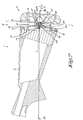
- the stick 1 according to the invention shown in the figure 1 comprises a body 2 and a base plate 3 mounted at the rear of the body 2 of the butt.
- the base plate 3 is part of a layer plate assembly 4 also comprising a layer plate 5 mounted on the base plate 3 via means 6 to adapt the position of the butt plate 5 screws. with respect to the base plate 3 and therefore vis-à-vis the stock 1.
- the butt plate 5 is composed of a support plate 7 and a layer 8 of flexible constitution to partially absorb the recoil shock of the weapon during a shot.
- buttplate 5 is generally known but is usually applied in a fixed manner directly on back of butt 1.
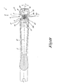
- the means 6 for adapting the position of the layer plate 5 are formed by a single single ball 9 which is formed by a spherical protrusion 10 of the support plate 7 of the layer plate 5, this protrusion 10 being housed in a concentric spherical recess 11 of the base plate 3 of the butt 1.
- the spherical hollow 11 is formed by a wall 12 of the base plate delimiting a cavity 13 of the base plate 3 of the butt 1, the spherical protuberance 10 being retained in the spherical recess 11 by means of a bolt 14 passing through the protrusion 10 and the wall 12 by a radial passage 15 in the spherical protuberance 10 and an opening 16 in the wall 12 respectively.
- the bolt 14 is screwed into a nut 17 housed in the cavity 13 on the other side of the wall 12, the stroke of the bolt 14 being sufficient to block the position of the ball 9 in any desired position.
- the passage 15 is preferably a cylindrical passage whose diameter corresponds mainly to the diameter of the bolt 14, while the opening 16 is characterized by dimensions greater than the diameter of the bolt 14, so that the bolt 14 can move in this opening 16 by the operation of the ball 9.
- the bolt head has a hexagonal hole 18 for a hexagonal key, the orifice being accessible from the outside by a passage 19 in the layer plate 5.
- the ball 9 is located mainly in the center of the base plate 3 and in the center of the support plate 7 of the layer plate 5.
- the rear surface 20 of the butt 1 formed by the rear surface of the base plate 3 has a conical shape converging towards the outside.
- the ball 9 is located at the point of convergence of this surface 20.
- the ball 9 makes it possible to adapt the position of the buttplate 5 with respect to the butt so as to be able to customize the position of the buttplate 5 to the shooter with respect to a neutral average position represented in FIGS. Figures 1 to 3 wherein the butt plate 5 is located mainly in the extension of the butt.
- the conical shape of the rear surface 20 limits the rotations about the X-X 'and Y-Y' axes, this surface forming a stop for the support plate 7.
- the maximum angle of rotation X ° about the transverse axis X-X ' is preferably at least five degrees or better still at least ten degrees and preferably about thirteen degrees relative to the average position.
- the maximum angle of rotation Y ° around yaw axis Y-Y ' is preferably at least four degrees or better still at least six degrees, preferably about eight degrees relative to the average position.
- the maximum angle of rotation Z ° around the longitudinal axis ZZ ' is preferably at least ten degrees or better still at least twenty degrees, preferably between twenty and twenty-five degrees from the average position
- FIGS. 7 and 8 show an example of such an embodiment in which the spherical ball 9 has been replaced by a double hinge 22 which allows a rotation of the layer plate 5 around two orthogonal axes, respectively around the transverse axis XX 'and around yaw axis Y-Y '.
- This double joint 22 is formed by an intermediate piece 23 which, on one side, is provided with a groove 24 whose bottom is curved in a concave manner to allow the sliding of a protuberance 25 of the support plate 7 in the form of a circle segment pivotable in the groove 24 about the YY axis, and which on the other side is in the form of a circle segment 26 which can pivot a similar way in a curved groove 27 made outside the wall 12 of the base plate 3 for pivoting about the axis X-X '.
- the intermediate piece is held in place by a bolt 14 passing through the support plate 7, the intermediate piece 23 and the wall 12 of the base plate 3 and by a nut 17 inside the wall 12, the nut 17 being guided in a groove 28.
- the locking of the double joint 22 is done by tightening the bolt 14 whose head is accessible through the passage 19.
- FIG. 9 Another embodiment of a butt (1) with a layer plate (5) according to the invention is shown in the figure 9 in which the means 6 are made by a simple ball joint 9, but which differs from the ball 9 of the figure 1 in that the spherical protuberance 10 and the spherical recess 11 are inverted, the spherical recess being formed by a wall 12 forming part of the support plate 7.
- the bolt 14 is now screwed into a thread of the protrusion 10, acting as a nut 17, through a spherical washer 29 and an opening 16 in the wall 12 of the support plate 7.
- the layer plate assembly 4 is provided with a set of spacers 30 making it possible to vary the length of the butt 1 by mounting for example between the butt plate 5 and the plate of support 7 as represented in the figure 10 , or by mounting between the body 2 of the stick 1 and the base plate 3.
- this spacer 30 is provided with a passage 31 to pass the clamping tool that allows to block the ball 9 by tightening the bolt 14.
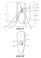
- the figure 11 shows a variant of the layer 5 of Figures 1 to 6 which is provided with three additional graduations 32, 33 and 34 for locating the position of the buttplate 5 with respect to a neutral position.
- a graduation 32 to indicate the inclination value of the buttplate 5 around the transverse axis X-X '
- a graduation 33 to indicate the rotational position of the buttplate 5 around yaw axis YY 'and a graduation 34 to indicate the rotational position of the layer plate 5 about the longitudinal axis Z-Z '.
- Reading the position of a marker for each of the graduations makes it possible to identify a given position of the diaper plate 5 and to put back the diaper 5 to at any time in this same position by putting the marks in the same position vis-à-vis the graduations 32, 33 and 34.
- the mark can be formed by the edge 36 of the spherical hollow 11.
Landscapes
- Engineering & Computer Science (AREA)
- General Engineering & Computer Science (AREA)
- Pivots And Pivotal Connections (AREA)
- Toys (AREA)
- Aiming, Guidance, Guns With A Light Source, Armor, Camouflage, And Targets (AREA)
- Golf Clubs (AREA)
Abstract
Description
L'invention concerne une crosse avec plaque de couche pour une arme à feu à épaule, par exemple pour une carabine ou un fusil de chasse.The invention relates to a butt with a buttplate for a shoulder firearm, for example for a rifle or a shotgun.
Une arme à feu à épaule est pourvue d'une crosse pour appuyer l'arme contre l'épaule et/ou contre la joue du tireur.A shoulder gun is provided with a butt to support the weapon against the shoulder and / or the shooter's cheek.
Un inconvénient de ce type d'arme est que, lors d'un tir, l'épaule du tireur subit un choc assez violent à cause du recul de l'arme occasionné par les forces de réaction des gaz formés par l'inflammation de la poudre de la cartouche percutée, dont la balle ou le plomb est expulsé du canon par la propulsion de ces gaz.A disadvantage of this type of weapon is that, during a shot, the shooter's shoulder suffers a rather violent shock due to the recoil of the weapon caused by the reaction forces of the gases formed by the ignition of the gun. powder of the percussion cartridge, whose bullet or lead is expelled from the barrel by the propulsion of these gases.
Un autre inconvénient lié aux forces de recul est que le tireur est un peu déséquilibré à chaque coup tiré, ce qui se répercute dans le fait que chaque fois il doit reprendre son équilibre pour avoir une position stable pour le tir suivant.Another disadvantage related to recoil forces is that the shooter is a little unbalanced with each shot, which is reflected in the fact that each time he must regain his balance to have a stable position for the next shot.
Cela se traduit par un manque de précision du tir ou par une cadence de tir réduite et par un manque de confort pour le tireur.This results in a lack of accuracy of the shot or a reduced rate of fire and a lack of comfort for the shooter.
Afin de donner un certain confort lors du tir, il est connu d'employer différents systèmes d'amortissement tels qu'une protection souple fixée d'une manière rigide sur le corps de la crosse et couvrant la partie arrière du corps de la crosse, une telle protection étant connue sous le non de plaque de couche.In order to give a certain comfort during the firing, it is known to use different damping systems such as a flexible protection fixed rigidly on the body of the butt and covering the rear part of the body of the butt, such protection being known as the non-butt plate.
Malgré la présence d'une plaque de couche, les forces que le tireur doit encaisser au niveau de l'épaule restent importantes.Despite the presence of a buttock, the forces that the shooter must cash in the shoulder remain important.
L'effet du choc de recul peut être apaisé aussi en personnalisant la plaque de couche aux mensurations de l'utilisateur.The effect of the recoil shock can also be calmed by customizing the butt plate to the user's measurements.
Cette solution est chère et demande l'intervention d'un homme de métier.This solution is expensive and requires the intervention of a skilled person.
L'arme est uniquement adaptable pour le confort de tir d'une seule personne.The weapon is only adaptable for the comfort of shooting of one person.
L'effet est différent selon par exemple les vêtements portés par le tireur.The effect is different according to for example the clothes worn by the shooter.
Généralement, la plaque de couche n'est pas personnalisée sur le tireur, surtout si l'arme est utilisée par plusieurs utilisateurs.Generally, the buttplate is not personalized on the shooter, especially if the weapon is used by several users.
La demande d'utilité
Le brevet
Le but de l'invention est de remédier aux inconvénients susdits et de réduire la répercussion du tir sur l'épaule pour donner un plus grand confort au tireur et une manipulation plus précise de l'arme.The object of the invention is to overcome the aforementioned drawbacks and to reduce the repercussion of the shot on the shoulder to give greater comfort to the shooter and a more precise handling of the weapon.
Ce but est atteint par le développement d'une crosse avec plaque de couche étant montée à l'arrière du corps de la crosse par l'intermédiaire de moyens, sous forme d'une seule rotule, permettant d'adapter la position de la plaque de couche vis-à-vis du corps de la crosse de façon à pouvoir personnaliser la position de la plaque de couche au tireur par rapport à une position moyenne dans laquelle la plaque de couche est située principalement dans le prolongement du corps de la crosse et principalement dans une position transversale à l'axe de symétrie moyen du corps de la crosse et en ce que la rotule est formée par une protubérance sphérique de la plaque de couche ou de la crosse, cette protubérance étant logée dans un creux sphérique respectivement de la crosse ou de la plaque de couche, ce creux sphérique étant formé par une paroi et en ce que la protubérance sphérique est retenue dans la creux sphérique au moyen d'un boulon traversant la paroi par une ouverture et au moyen d'un écrou dans lequel le boulon est vissé.This object is achieved by the development of a butt with a base plate being mounted at the rear of the body of the butt by means of means, in the form of a single ball joint, to adapt the position of the plate layer relative to the body of the butt so as to customize the position of the buttplate to the shooter relative to an average position in which the buttock is located mainly in the extension of the body of the stock and mainly in a position transverse to the mean axis of symmetry of the body of the butt and in that the ball is formed by a spherical protrusion of the butt plate or the butt, this protuberance being housed in a spherical recess respectively of the stick or the butt plate, this spherical hollow being formed by a wall and that the spherical protrusion is retained in the spherical recess by means of a bolt passing through the wall through an opening and by means of a nut in which the bolt is screwed.
Une crosse selon l'invention permet une adaptation pratiquement parfaite et simple de la plaque de couche contre le corps du tireur.A butt according to the invention allows a virtually perfect and simple adaptation of the butt plate against the body of the shooter.
Cette plaque de couche est réglée pour épouser le corps du tireur. De ce fait, la surface en contact avec le corps du tireur est très largement augmentée par rapport à une crosse avec une plaque de couche fixe. La surface de contact peut augmenter avec un facteur vingt.This buttock is set to fit the shooter's body. As a result, the area in contact with the shooter's body is greatly increased compared to a butt with a fixed layer plate. The contact area can increase by a factor of twenty.
De cette manière la force de recul de l'arme est répartie sur une plus grande surface de contact entre la plaque de couche et l'épaule du tireur, ce qui diminue la pression ressenti par le tireur et donc les effets négatifs de la force de recul.In this way the recoil force of the weapon is distributed over a greater contact area between the butt plate and the shooter's shoulder, which reduces the pressure felt by the shooter and therefore the negative effects of the force of the shooter. decline.
Outre le fait de diminuer la pression sur le corps, le système selon l'invention permet au tireur de se fondre avec scn arme. Cela procure une meilleure sensation au tir. De la même manière que s'il avait une crosse réalisée à ses mensurations, le tireur peut personnaliser son arme.In addition to decreasing the pressure on the body, the system according to the invention allows the shooter to melt with a weapon. This provides a better shooting sensation. In the same way that if he had a stick made to his measurements, the shooter can customize his weapon.
Le système selon l'invention s'adapte au tireur, quelles que scient les conditions, peu importe les vêtements légers ou épais du tireur.The system according to the invention adapts to the shooter, whatever the conditions are, regardless of the light or thick clothing of the shooter.
Selon l'invention les moyens susdits sont réalisés par une seule rotule qui est montée de préférence au centre de la surface arrière du corps de la crosse et permettant de faire pivoter la plaque de couche autour d'au moins un axe de rotation et de préférence autour de trois axes orthogonaux.According to the invention, the aforesaid means are made by a single ball joint which is preferably mounted in the center of the rear surface of the body of the stock and makes it possible to pivot the bedplate around at least one axis of rotation and preferably around three orthogonal axes.
Une telle rotule permet une adaptation de la position de la plaque de couche à pratiquement n'importe quelle situation de morphologie du tireur, des vêtements portés par le tireur, et ainsi de suite.Such a patella allows adaptation of the position of the butt plate to virtually any situation of morphology of the shooter, clothing worn by the shooter, and so on.
D'une manière pratique, la rotule est blocable de façon à pouvoir fixer la rotule en position pour bloquer la position de la plaque de couche par rapport au corps de la crosse dans une position adaptée au tireur.In practice, the ball is lockable so as to fix the ball in position to block the position of the buttress plate relative to the body of the stock in a position adapted to the shooter.
Le blocage se fait selon l'invention au moyen d'un boulon de blocage dont la tête est accessible de l'extérieure pour un outil de serrage, par exemple une clé hexagonale, par un passage dans la plaque de couche.Blocking is according to the invention by means of a locking bolt whose head is accessible from the outside for a clamping tool, for example a hexagonal key, by a passage in the butt plate.
Le blocage et déblocage est donc facile et adéquat et ne nécessite pas beaucoup de manipulation pour changer la position de la plaque de couche.The locking and unlocking is easy and adequate and does not require much manipulation to change the position of the butt plate.
Optionnellement la crosse peut être complétée par un jeu d'entretoises permettant de faire varier la longueur de crosse.Optionally the stock can be completed by a set of spacers to vary the length of the stock.
L'invention concerne aussi un ensemble de plaque de couche comprenant une plaque de base pour montage à l'arrière du corps d'une crosse d'une arme à feu à épaule et comprenant une plaque de couche montée sur la plaque de base par l'intermédiaire de moyens, sous forme d'une seule rotule, permettant d'adapter la position de la plaque de couche vis-à-vis de la plaque de base de façon à pouvoir personnaliser la position de la plaque de couche au tireur par rapport à une position moyenne.The invention also relates to a set of bedplate comprising a base plate for mounting at the back of the body of a butt of a shoulder firearm and comprising a butt plate mounted on the base plate by means of means, in the form of a single patella, to adapt the position of the buttplate vis-à-vis the base plate so as to customize the position of the layer to the shooter relative to an average position.
Un tel ensemble peut être monté à l'arrière du corps de la crosse en lieu et place d'une plaque de couche fixe traditionnelle, permettant d'adapter la plaque de couche à la morphologie du tireur.Such an assembly can be mounted at the rear of the body of the butt instead of a traditional fixed layer plate, to adapt the butt plate to the morphology of the shooter.
Pour plus de clarté, quelques exemples de réalisation d'une crosse avec plaque de couche selon l'invention pour une arme à feu à épaule sont décrits ci-après à titre illustratif et non restrictif, référence étant faite aux dessins annexés dans lesquels:
- La
figure 1 représente une coupe longitudinale schématisé d'une crosse avec une plaque de couche selon l'invention; - la
figure 2 représente une coupe selon la ligne II-II de lafigure 1 ; - la
figure 3 représente une vue arrière dans la direction de la flèche F3 de lafigure 1 ; - les
figures 4 à 6 représentent des vues semblables à celles desfigures 1 à 3 respectivement, mais pour une position de la plaque de couche ; - la
figure 7 représente une coupe longitudinale analogue à lafigure 1 , mais pour une autre réalisation d'une crosse avec plaque de couche selon l'invention; - la
figure 8 est une coupe selon la ligne VIII-VIII de lafigure 7 ; - la
figure 9 représente une coupe longitudinale d'une autre variante d'une crosse selon l'invention; - la
figure 10 représente une variante de la crosse avec plaque de couche de lafigure 1 ; - la
figure 11 est une illustration d'une variante pourvue de graduations; - la
figure 12 représente la plaque de couche indiquée par la flèche F12 en état démonté.
- The
figure 1 is a schematic longitudinal section of a butt with a butt plate according to the invention; - the
figure 2 represents a section along line II-II of thefigure 1 ; - the
figure 3 represents a rear view in the direction of the arrow F3 of thefigure 1 ; - the
Figures 4 to 6 represent views similar to those ofFigures 1 to 3 respectively, but for a position of the butt plate; - the
figure 7 represents a longitudinal section analogous tofigure 1 , but for another embodiment of a stick with a butt plate according to the invention; - the
figure 8 is a section along the line VIII-VIII of thefigure 7 ; - the
figure 9 represents a longitudinal section of another variant of a stick according to the invention; - the
figure 10 represents a variant of the lacrosse with a buttplate of thefigure 1 ; - the
figure 11 is an illustration of a variant provided with graduations; - the
figure 12 represents the plate indicated by the arrow F12 in disassembled state.
La crosse 1 selon l'invention représentée dans la
La plaque de base 3 fait partie d'un ensemble de plaque de couche 4 comprenant également une plaque de couche 5 montée sur la plaque de base 3 par l'intermédiaire de moyens 6 permettant d'adapter la position de la plaque de couche 5 vis-à-vis de la plaque de base 3 et donc vis-à-vis de la crosse 1.The
La plaque de couche 5 est composée d'une plaque de support 7 et d'une couche 8 de constitution souple permettant d'absorber en partie le choc de recul de l'arme lors d'un tir.The
Ce genre de plaque de couche 5 est généralement connu mais est appliqué d'habitude d'une manière fixe directement sur l'arrière de crosse 1.This kind of
Dans l'exemple représenté, les moyens 6 permettant d'adapter la position de la plaque de couche 5 sont formés par une seule rotule 9 simple qui est formée par une protubérance sphérique 10 de la plaque de support 7 de la plaque de couche 5, cette protubérance 10 étant logée dans un creux sphérique 11 concentrique de la plaque de base 3 de la crosse 1.In the example shown, the means 6 for adapting the position of the
Le creux sphérique 11 est formé par une paroi 12 de la plaque de base délimitant une cavité 13 de la plaque de base 3 de la crosse 1, la protubérance sphérique 10 étant retenue dans le creux sphérique 11 au moyen d'un boulon 14 traversant la protubérance 10 et la paroi 12 par un passage radial 15 dans la protubérance sphérique 10 et par une ouverture 16 dans la paroi 12 respectivement.The
Le boulon 14 est vissé dans un écrou 17 logé dans la cavité 13 de l'autre côté de la paroi 12, la course du boulon 14 étant suffisante pour permettre de bloquer la position de la rotule 9 dans n'importe quelle position désirée.The
Le passage 15 est de préférence un passage cylindrique dont le diamètre correspond principalement avec le diamètre du boulon 14, tandis que l'ouverture 16 est caractérisée par des dimensions plus grandes que le diamètre du boulon 14, de façon à ce que le boulon 14 puisse bouger dans cet ouverture 16 par l'opération de la rotule 9.The
La tête du boulon est pourvue d'un orifice hexagonal 18 pour une clef hexagonale, l'orifice étant accessible de l'extérieure par un passage 19 dans la plaque de couche 5.The bolt head has a
La rotule 9 est située principalement au centre de la plaque de base 3 et au centre de la plaque de support 7 de la plaque de couche 5.The ball 9 is located mainly in the center of the
La surface arrière 20 de la crosse 1 formée par la surface arrière de la plaque de base 3 a une forme conique convergente vers l'extérieure. La rotule 9 se situe au point de convergence de cette surface 20.The
La rotule 9 permet d'adapter la position de la plaque de couche 5 vis-à-vis de la crosse de façon à pouvoir personnaliser la position de la plaque de couche 5 au tireur par rapport à une position moyenne neutre représentée dans les
La rotule permet plus spécialement une rotation autour de trois axes orthogonaux, respectivement :
- une rotation X en inclinaison de la plaque de couche 5 dans le plan moyen de symétrie 21 de la crosse 1, c'est-à-dire une rotation X autour d'un axe transversal X-X' perpendiculaire au plan moyen de symétrie 21 de la crosse 1 comme illustrée dans la
figure 4 ; - une rotation latérale Y autour d'un axe de lacet Y-Y' situé principalement dans le plan moyen de symétrie 21 de la crosse 1, par exemple parallèle à la plaque de
support 7 comme illustrée dans lafigure 5 ; - une rotation Z autour d'un axe longitudinal Z-Z' perpendiculaire aux axes X-X' et Y-Y' comme illustrée dans la
figure 6 .
- a rotation X in inclination of the
layer plate 5 in the mean plane ofsymmetry 21 of the stick 1, that is to say a rotation X about a transverse axis XX 'perpendicular to the mean plane ofsymmetry 21 of the lacrosse 1 as illustrated in thefigure 4 ; - a lateral rotation Y about a Y-y 'yaw axis located mainly in the mean plane of
symmetry 21 of the stick 1, for example parallel to thesupport plate 7 as illustrated in FIG.figure 5 ; - a rotation Z about a longitudinal axis ZZ 'perpendicular to the axes XX' and YY 'as illustrated in FIG.
figure 6 .
La forme conique de la surface arrière 20 limite les rotations autour des axes X-X' et Y-Y', cette surface 20 formant une butée pour la plaque de support 7.The conical shape of the
Les possibilités de rotation peuvent également ou alternativement être limitées par la forme de l'ouverture 16, limitant les mouvements du boulon 14 dans cette ouverture 16.The possibilities of rotation can also be alternatively limited by the shape of the
L'angle de rotation maximale X° autour de l'axe transversal X-X' est de préférence d'au moins cinq degrés ou mieux d'au moins dix degrés et de préférence d'environ treize degrés par rapport à la position moyenne.The maximum angle of rotation X ° about the transverse axis X-X 'is preferably at least five degrees or better still at least ten degrees and preferably about thirteen degrees relative to the average position.
L'angle de rotation maximale Y° autour de l'axe de lacet Y-Y' est de préférence d'au moins quatre degrés ou mieux d'au moins six degrés, de préférence d'environ huit degrés par rapport à la position moyenne.The maximum angle of rotation Y ° around yaw axis Y-Y 'is preferably at least four degrees or better still at least six degrees, preferably about eight degrees relative to the average position.
L'angle de rotation maximale Z° autour de l'axe de longitudinale Z-Z' est de préférence d'au moins dix degrés ou mieux d'au moins vingt degrés, de préférence entre vingt et vingt-cinq degrés par rapport à la position moyenneThe maximum angle of rotation Z ° around the longitudinal axis ZZ 'is preferably at least ten degrees or better still at least twenty degrees, preferably between twenty and twenty-five degrees from the average position
Il est clair que dans le cas de la rotule 9 les axes X-X', Y-Y' et Z-Z' se croisent principalement dans un point, ce qui n'est pas absolument nécessaire pour l'invention mais qui facilite le réglage et ce qui permet une meilleure distribution de la force de recul sur l'épaule du tireur.It is clear that in the case of the ball 9 axes X-X ', YY' and ZZ 'intersect mainly in a point, which is not absolutely necessary for the invention but which facilitates the adjustment and what allows a better distribution of the force of recoil on the shooter's shoulder.
Il n'est pas exclu limiter le nombre d'axes de rotation et de ne permettre une rotation autour d'un seul axe, par exemple l'axe Y-Y', ou autour de deux axes, par exemple les axes Y-Y' et Z-Z' et d'empêcher d'autres rotations.It is not impossible to limit the number of axes of rotation and to allow rotation about a single axis, for example the Y-axis Y ', or around two axes, for example the axes YY' and ZZ 'and prevent further rotations.
Il est clair que la rotation autour des différents axes de rotation X-X', Y-Y' et Z-Z' peut se faire d'une manière simultanée et que le blocage peut s'effectuer tout simplement en serrant le boulon 14. Il n'est pas exclu toutefois que chaque rotation est réalisée par une articulation et un blocage indépendant de l'autre.It is clear that the rotation around the various axes of rotation X-X ', YY' and ZZ 'can be done simultaneously and that the blocking can be done simply by tightening the
Les
Cette articulation double 22 est réalisée par une pièce intermédiaire 23 qui, d'un côté, est pourvue d'une rainure 24 dont le fond est bombé d'une manière concave pour permettre le coulissement d'une protubérance 25 de la plaque de support 7 sous forme d'un segment de cercle pouvant pivoter dans la rainure 24 autour de l'axe Y-Y', et qui, de l'autre côté, a la forme d'un segment de cercle 26 pouvant pivoter d'une manière analogue dans une rainure bombée 27 réalisée à l'extérieure de la paroi 12 de la plaque de base 3 pour un pivotement autour de l'axe X-X'.This double joint 22 is formed by an
La pièce intermédiaire est tenue en place par un boulon 14 traversant la plaque de support 7, la pièce intermédiaire 23 et la paroi 12 de la plaque de base 3 et par un écrou 17 à l'intérieure de la paroi 12, l'écrou 17 étant guidé dans une rainure 28.The intermediate piece is held in place by a
Le blocage de l'articulation double 22 se fait par le serrage du boulon 14 dont la tête est accessible par le passage 19.The locking of the double joint 22 is done by tightening the
Une autre réalisation d'une crosse (1) avec une plaque de couche (5) selon l'invention est montrée dans la
Le boulon 14 se visse maintenant dans un filetage de la protubérance 10, faisant office d'écrou 17, à travers une rondelle sphérique 29 et une ouverture 16 dans la paroi 12 de plaque de support 7.The
Rien empêche que la surface arrière 20 de la crosse 1 soit plate et que la plaque de support 7 ait une forme conique ou qu'alternativement les deux aient une forme conique ou même qu'aucun des deux aient une forme conique si les limitations des rotations sont réalisées dans les moyens 6 mêmes, par exemple dans la rotule 9 ou dans l'articulation 22.There is nothing to prevent the
Selon une autre caractéristique de l'invention, l'ensemble de plaque de couche 4 est pourvue d'un jeu d'entretoises 30 permettant de faire varier la longueur de la crosse 1 par montage par exemple entre la plaque de couche 5 et la plaque de support 7 comme représentées dans la
Dans le cas d'une entretoise 30 entre la plaque de couche 5 et la plaque de support 7, cette entretoise 30 est pourvue d'un passage 31 pour faire passer l'outil de serrage qui permet de bloquer la rotule 9 en serrant le boulon 14.In the case of a
La
Il s'agit respectivement d'une graduation 32 pour indiquer la valeur d'inclinaison de la plaque de couche 5 autour de l'axe transversal X-X', d'une graduation 33 pour indiquer la position de rotation de la plaque de couche 5 autour de l'axe de lacet Y-Y' et d'une graduation 34 pour indiquer la position de rotation de la plaque de couche 5 autour de l'axe longitudinale Z-Z'.These are respectively a
La lecture de la position d'un repère pour chacune des graduations, par exemple la position d'un repère 35 pour la graduation 34, permet d'identifier une position donnée de la plaque de couche 5 et de remettre la plaque de couche 5 à tout moment dans cette même position en remettant les repères dans la même position vis-à-vis des graduations 32, 33 et 34.Reading the position of a marker for each of the graduations, for example the position of a
Pour les graduations 32 et 33 le repère peut être formé par le bord 36 du creux sphérique 11.For the
Il est évident que l'invention n'est nullement limitée aux exemples décrits ci-avant mais que de nombreuses modifications peuvent être apportées à la crosse avec plaque de couche selon l'invention pour une arme à feu à épaule sans sortir du cadre de l'invention telle que définie dans les revendications suivantes.It is obvious that the invention is in no way limited to the examples described above, but that many modifications can be made to the buttplate according to the invention for a firearm to shoulder without departing from the scope of the invention. invention as defined in the following claims.
Claims (18)
Priority Applications (1)
| Application Number | Priority Date | Filing Date | Title |
|---|---|---|---|
| US13/534,156 US8499483B2 (en) | 2011-06-28 | 2012-06-27 | Butt with recoil pad for a shoulder-held firearm |
Applications Claiming Priority (1)
| Application Number | Priority Date | Filing Date | Title |
|---|---|---|---|
| BE2011/0392A BE1020036A5 (en) | 2011-06-28 | 2011-06-28 | CROSSE WITH LAYER PLATE FOR SHOULDER ARM. |
Publications (2)
| Publication Number | Publication Date |
|---|---|
| EP2541188A1 true EP2541188A1 (en) | 2013-01-02 |
| EP2541188B1 EP2541188B1 (en) | 2015-03-04 |
Family
ID=46051643
Family Applications (1)
| Application Number | Title | Priority Date | Filing Date |
|---|---|---|---|
| EP12003789.0A Active EP2541188B1 (en) | 2011-06-28 | 2012-05-14 | Stock with butt plate for a long gun |
Country Status (5)
| Country | Link |
|---|---|
| US (1) | US8499483B2 (en) |
| EP (1) | EP2541188B1 (en) |
| BE (1) | BE1020036A5 (en) |
| ES (1) | ES2534886T3 (en) |
| PT (1) | PT2541188E (en) |
Cited By (3)
| Publication number | Priority date | Publication date | Assignee | Title |
|---|---|---|---|---|
| US10036602B1 (en) | 2017-11-28 | 2018-07-31 | Magpul Industries Corp. | Interchangeable plates for a firearm |
| WO2019006486A1 (en) * | 2017-07-05 | 2019-01-10 | Schoenborn Damian | Device for adjusting the orientation of a rear stock of a portable firearm |
| USD868924S1 (en) | 2018-01-10 | 2019-12-03 | Magpul Industries Corp. | Firearm stock |
Families Citing this family (5)
| Publication number | Priority date | Publication date | Assignee | Title |
|---|---|---|---|---|
| US9417033B2 (en) * | 2014-08-28 | 2016-08-16 | Fulcrum Concepts LLC | Adjustable firearm stock adapter assembly |
| USD804602S1 (en) | 2016-01-12 | 2017-12-05 | Magpul Industries Corp. | Firearm stock |
| ES2755480A1 (en) * | 2018-10-22 | 2020-04-22 | Aguirre Eduardo Ijalba | Multi-adjustable shock absorber and weapon (Machine-translation by Google Translate, not legally binding) |
| US11953289B2 (en) | 2021-11-30 | 2024-04-09 | John W Angers, Jr. | Adjustable, pivoting gun stock and method of use |
| US11732998B2 (en) | 2021-11-30 | 2023-08-22 | John W Angers, Jr. | Adjustable, pivoting rifle stock and method of use |
Citations (4)
| Publication number | Priority date | Publication date | Assignee | Title |
|---|---|---|---|---|
| US1468354A (en) | 1922-12-07 | 1923-09-18 | John F Caretto | Adjustable gun stock |
| DE9411466U1 (en) * | 1994-07-15 | 1994-11-10 | Westinger & Altenburger | Stock for a precision firearm with a cheek piece and / or a butt plate |
| EP1688696A1 (en) * | 2005-02-04 | 2006-08-09 | S.A.T. Swiss Arms Technology AG | Adjustable butt-plate for hand gun |
| DE202007012495U1 (en) | 2007-09-05 | 2008-01-17 | TEC-HRO shooting equipment GbR (vertretungsberechtigte Gesellschafter: Herr Christoph Häßler | Buttplate for a sports rifle |
Family Cites Families (7)
| Publication number | Priority date | Publication date | Assignee | Title |
|---|---|---|---|---|
| US243553A (en) * | 1881-06-28 | Albeet hape and alfeed s | ||
| US843227A (en) * | 1906-10-04 | 1907-02-05 | Homer W Munson | Jointed gun-stock. |
| US1480350A (en) * | 1921-11-07 | 1924-01-08 | George H Martin | Gun |
| US2453394A (en) * | 1946-05-22 | 1948-11-09 | Emil R Wittman | Adjustable gunstock |
| BE492193A (en) * | 1948-11-16 | |||
| US2754608A (en) * | 1955-01-19 | 1956-07-17 | Jr Ray H Stieffel | Shock absorption mechanism for firearms |
| DE2832015A1 (en) * | 1978-07-20 | 1980-01-31 | Anschuetz Gmbh J G | HOLDING AND ADJUSTING DEVICE FOR THE PISTOL HANDLE OF A FIREARM, IN PARTICULAR A TRIPLE COMPETITION RIFLE |
-
2011
- 2011-06-28 BE BE2011/0392A patent/BE1020036A5/en active
-
2012
- 2012-05-14 EP EP12003789.0A patent/EP2541188B1/en active Active
- 2012-05-14 PT PT12003789T patent/PT2541188E/en unknown
- 2012-05-14 ES ES12003789.0T patent/ES2534886T3/en active Active
- 2012-06-27 US US13/534,156 patent/US8499483B2/en active Active
Patent Citations (4)
| Publication number | Priority date | Publication date | Assignee | Title |
|---|---|---|---|---|
| US1468354A (en) | 1922-12-07 | 1923-09-18 | John F Caretto | Adjustable gun stock |
| DE9411466U1 (en) * | 1994-07-15 | 1994-11-10 | Westinger & Altenburger | Stock for a precision firearm with a cheek piece and / or a butt plate |
| EP1688696A1 (en) * | 2005-02-04 | 2006-08-09 | S.A.T. Swiss Arms Technology AG | Adjustable butt-plate for hand gun |
| DE202007012495U1 (en) | 2007-09-05 | 2008-01-17 | TEC-HRO shooting equipment GbR (vertretungsberechtigte Gesellschafter: Herr Christoph Häßler | Buttplate for a sports rifle |
Cited By (6)
| Publication number | Priority date | Publication date | Assignee | Title |
|---|---|---|---|---|
| WO2019006486A1 (en) * | 2017-07-05 | 2019-01-10 | Schoenborn Damian | Device for adjusting the orientation of a rear stock of a portable firearm |
| US10907931B2 (en) | 2017-07-05 | 2021-02-02 | Damian SCHOENBORN | Device for adjusting the orientation of a rear stock of a portable firearm |
| US10036602B1 (en) | 2017-11-28 | 2018-07-31 | Magpul Industries Corp. | Interchangeable plates for a firearm |
| US10386138B2 (en) | 2017-11-28 | 2019-08-20 | Magpul Industries Corp. | Interchangeable plates for a firearm |
| US10895425B2 (en) | 2017-11-28 | 2021-01-19 | Magpul Industries Corp. | Interchangeable plates for a firearm |
| USD868924S1 (en) | 2018-01-10 | 2019-12-03 | Magpul Industries Corp. | Firearm stock |
Also Published As
| Publication number | Publication date |
|---|---|
| PT2541188E (en) | 2015-03-20 |
| US20130000175A1 (en) | 2013-01-03 |
| ES2534886T3 (en) | 2015-04-29 |
| BE1020036A5 (en) | 2013-04-02 |
| EP2541188B1 (en) | 2015-03-04 |
| US8499483B2 (en) | 2013-08-06 |
Similar Documents
| Publication | Publication Date | Title |
|---|---|---|
| EP2541188B1 (en) | Stock with butt plate for a long gun | |
| US9429384B2 (en) | Archery release aid | |
| FR2510247A1 (en) | SHOOTING ARM, IN PARTICULAR A LONG CANON | |
| US9410763B2 (en) | Angle-adjustable buffer tube system | |
| FR2586797A1 (en) | VISEE SYSTEM FOR A COMPETITION GUN OR THE LIKE | |
| FR2589230A1 (en) | ADJUSTABLE PISTOL HANDLE | |
| EP3555549B1 (en) | Articulated stock for shoulder-fired weapon | |
| EP1092936B1 (en) | Firearm having at least two barrels with adjustable geometry and method for adjusting said geometry | |
| WO1998027399A1 (en) | Short gun with barrel in the extension of the stock | |
| EP1522815B1 (en) | Device for correcting the trajectory of ball projectiles for a replica weapon | |
| EP1589313A2 (en) | Accessory for hunters | |
| WO2020120418A1 (en) | Gun heel | |
| BE1015572A3 (en) | Semi-automatic weapon such as carbine has reloading gas cylinder controlled by regulating screw with portion having same section as cylinder chamber | |
| EP0278795B1 (en) | Firearm percussion device for firing cartridges of two different calibres | |
| FR2811419A1 (en) | Gun for competitive shooting includes adjustable supports for hands and shoulder to suit shape and size of user | |
| FR3017702A1 (en) | RIFLE WITH TWO GUNS JUXTAPOSES | |
| FR2795169A1 (en) | Resting part for butt of firearm uses screws going through vertical elongated holes along its sides, tightening/untightening of screws modifying position of resting part relative to butt | |
| FR3134886A1 (en) | AMBIDEXTROUS ARC GRIP MADE OF A GRIP AND A GRIP BODY AND ASSOCIATED ARC | |
| FR3062716A1 (en) | ADJUSTING DEVICE FOR A RIFLE SHAFT | |
| FR2580795A1 (en) | Bow | |
| FR2636418A1 (en) | Portable automatic weapon | |
| BE1015412A3 (en) | Firearm at least two guns geometry adjustable bunk and method for controlling the geometry. | |
| EP0990869B1 (en) | Sabot for a subcalibre projectile | |
| FR2552218A1 (en) | MORTAR CAPABLE OF MOUNTING ON A VEHICLE | |
| FR2855255A1 (en) | Aiming system for shooting weapon e.g. firearm, has cylindrical sleeve placed at free end of band of weapon barrel and block placed at intermediate point on barrel in axis of sleeve |
Legal Events
| Date | Code | Title | Description |
|---|---|---|---|
| PUAI | Public reference made under article 153(3) epc to a published international application that has entered the european phase |
Free format text: ORIGINAL CODE: 0009012 |
|
| AK | Designated contracting states |
Kind code of ref document: A1 Designated state(s): AL AT BE BG CH CY CZ DE DK EE ES FI FR GB GR HR HU IE IS IT LI LT LU LV MC MK MT NL NO PL PT RO RS SE SI SK SM TR |
|
| AX | Request for extension of the european patent |
Extension state: BA ME |
|
| 17P | Request for examination filed |
Effective date: 20121218 |
|
| GRAP | Despatch of communication of intention to grant a patent |
Free format text: ORIGINAL CODE: EPIDOSNIGR1 |
|
| INTG | Intention to grant announced |
Effective date: 20141006 |
|
| GRAS | Grant fee paid |
Free format text: ORIGINAL CODE: EPIDOSNIGR3 |
|
| GRAA | (expected) grant |
Free format text: ORIGINAL CODE: 0009210 |
|
| AK | Designated contracting states |
Kind code of ref document: B1 Designated state(s): AL AT BE BG CH CY CZ DE DK EE ES FI FR GB GR HR HU IE IS IT LI LT LU LV MC MK MT NL NO PL PT RO RS SE SI SK SM TR |
|
| REG | Reference to a national code |
Ref country code: GB Ref legal event code: FG4D Free format text: NOT ENGLISH |
|
| REG | Reference to a national code |
Ref country code: CH Ref legal event code: EP |
|
| REG | Reference to a national code |
Ref country code: PT Ref legal event code: SC4A Free format text: AVAILABILITY OF NATIONAL TRANSLATION Effective date: 20150310 |
|
| REG | Reference to a national code |
Ref country code: IE Ref legal event code: FG4D Free format text: LANGUAGE OF EP DOCUMENT: FRENCH |
|
| REG | Reference to a national code |
Ref country code: AT Ref legal event code: REF Ref document number: 714254 Country of ref document: AT Kind code of ref document: T Effective date: 20150415 |
|
| REG | Reference to a national code |
Ref country code: DE Ref legal event code: R096 Ref document number: 602012005454 Country of ref document: DE Effective date: 20150416 |
|
| REG | Reference to a national code |
Ref country code: ES Ref legal event code: FG2A Ref document number: 2534886 Country of ref document: ES Kind code of ref document: T3 Effective date: 20150429 |
|
| REG | Reference to a national code |
Ref country code: AT Ref legal event code: MK05 Ref document number: 714254 Country of ref document: AT Kind code of ref document: T Effective date: 20150304 Ref country code: NL Ref legal event code: VDEP Effective date: 20150304 |
|
| PG25 | Lapsed in a contracting state [announced via postgrant information from national office to epo] |
Ref country code: LT Free format text: LAPSE BECAUSE OF FAILURE TO SUBMIT A TRANSLATION OF THE DESCRIPTION OR TO PAY THE FEE WITHIN THE PRESCRIBED TIME-LIMIT Effective date: 20150304 Ref country code: HR Free format text: LAPSE BECAUSE OF FAILURE TO SUBMIT A TRANSLATION OF THE DESCRIPTION OR TO PAY THE FEE WITHIN THE PRESCRIBED TIME-LIMIT Effective date: 20150304 Ref country code: SE Free format text: LAPSE BECAUSE OF FAILURE TO SUBMIT A TRANSLATION OF THE DESCRIPTION OR TO PAY THE FEE WITHIN THE PRESCRIBED TIME-LIMIT Effective date: 20150304 Ref country code: FI Free format text: LAPSE BECAUSE OF FAILURE TO SUBMIT A TRANSLATION OF THE DESCRIPTION OR TO PAY THE FEE WITHIN THE PRESCRIBED TIME-LIMIT Effective date: 20150304 Ref country code: NO Free format text: LAPSE BECAUSE OF FAILURE TO SUBMIT A TRANSLATION OF THE DESCRIPTION OR TO PAY THE FEE WITHIN THE PRESCRIBED TIME-LIMIT Effective date: 20150604 |
|
| REG | Reference to a national code |
Ref country code: LT Ref legal event code: MG4D |
|
| PG25 | Lapsed in a contracting state [announced via postgrant information from national office to epo] |
Ref country code: LV Free format text: LAPSE BECAUSE OF FAILURE TO SUBMIT A TRANSLATION OF THE DESCRIPTION OR TO PAY THE FEE WITHIN THE PRESCRIBED TIME-LIMIT Effective date: 20150304 Ref country code: AT Free format text: LAPSE BECAUSE OF FAILURE TO SUBMIT A TRANSLATION OF THE DESCRIPTION OR TO PAY THE FEE WITHIN THE PRESCRIBED TIME-LIMIT Effective date: 20150304 Ref country code: GR Free format text: LAPSE BECAUSE OF FAILURE TO SUBMIT A TRANSLATION OF THE DESCRIPTION OR TO PAY THE FEE WITHIN THE PRESCRIBED TIME-LIMIT Effective date: 20150605 Ref country code: RS Free format text: LAPSE BECAUSE OF FAILURE TO SUBMIT A TRANSLATION OF THE DESCRIPTION OR TO PAY THE FEE WITHIN THE PRESCRIBED TIME-LIMIT Effective date: 20150304 |
|
| PG25 | Lapsed in a contracting state [announced via postgrant information from national office to epo] |
Ref country code: NL Free format text: LAPSE BECAUSE OF FAILURE TO SUBMIT A TRANSLATION OF THE DESCRIPTION OR TO PAY THE FEE WITHIN THE PRESCRIBED TIME-LIMIT Effective date: 20150304 |
|
| PG25 | Lapsed in a contracting state [announced via postgrant information from national office to epo] |
Ref country code: CZ Free format text: LAPSE BECAUSE OF FAILURE TO SUBMIT A TRANSLATION OF THE DESCRIPTION OR TO PAY THE FEE WITHIN THE PRESCRIBED TIME-LIMIT Effective date: 20150304 Ref country code: EE Free format text: LAPSE BECAUSE OF FAILURE TO SUBMIT A TRANSLATION OF THE DESCRIPTION OR TO PAY THE FEE WITHIN THE PRESCRIBED TIME-LIMIT Effective date: 20150304 Ref country code: SK Free format text: LAPSE BECAUSE OF FAILURE TO SUBMIT A TRANSLATION OF THE DESCRIPTION OR TO PAY THE FEE WITHIN THE PRESCRIBED TIME-LIMIT Effective date: 20150304 Ref country code: RO Free format text: LAPSE BECAUSE OF FAILURE TO SUBMIT A TRANSLATION OF THE DESCRIPTION OR TO PAY THE FEE WITHIN THE PRESCRIBED TIME-LIMIT Effective date: 20150304 |
|
| PG25 | Lapsed in a contracting state [announced via postgrant information from national office to epo] |
Ref country code: PL Free format text: LAPSE BECAUSE OF FAILURE TO SUBMIT A TRANSLATION OF THE DESCRIPTION OR TO PAY THE FEE WITHIN THE PRESCRIBED TIME-LIMIT Effective date: 20150304 Ref country code: IS Free format text: LAPSE BECAUSE OF FAILURE TO SUBMIT A TRANSLATION OF THE DESCRIPTION OR TO PAY THE FEE WITHIN THE PRESCRIBED TIME-LIMIT Effective date: 20150704 |
|
| REG | Reference to a national code |
Ref country code: DE Ref legal event code: R097 Ref document number: 602012005454 Country of ref document: DE |
|
| REG | Reference to a national code |
Ref country code: CH Ref legal event code: PL |
|
| PLBE | No opposition filed within time limit |
Free format text: ORIGINAL CODE: 0009261 |
|
| STAA | Information on the status of an ep patent application or granted ep patent |
Free format text: STATUS: NO OPPOSITION FILED WITHIN TIME LIMIT |
|
| PG25 | Lapsed in a contracting state [announced via postgrant information from national office to epo] |
Ref country code: DK Free format text: LAPSE BECAUSE OF FAILURE TO SUBMIT A TRANSLATION OF THE DESCRIPTION OR TO PAY THE FEE WITHIN THE PRESCRIBED TIME-LIMIT Effective date: 20150304 Ref country code: LI Free format text: LAPSE BECAUSE OF NON-PAYMENT OF DUE FEES Effective date: 20150531 Ref country code: CH Free format text: LAPSE BECAUSE OF NON-PAYMENT OF DUE FEES Effective date: 20150531 Ref country code: LU Free format text: LAPSE BECAUSE OF FAILURE TO SUBMIT A TRANSLATION OF THE DESCRIPTION OR TO PAY THE FEE WITHIN THE PRESCRIBED TIME-LIMIT Effective date: 20150514 Ref country code: MC Free format text: LAPSE BECAUSE OF FAILURE TO SUBMIT A TRANSLATION OF THE DESCRIPTION OR TO PAY THE FEE WITHIN THE PRESCRIBED TIME-LIMIT Effective date: 20150304 |
|
| 26N | No opposition filed |
Effective date: 20151207 |
|
| REG | Reference to a national code |
Ref country code: IE Ref legal event code: MM4A |
|
| PG25 | Lapsed in a contracting state [announced via postgrant information from national office to epo] |
Ref country code: SI Free format text: LAPSE BECAUSE OF FAILURE TO SUBMIT A TRANSLATION OF THE DESCRIPTION OR TO PAY THE FEE WITHIN THE PRESCRIBED TIME-LIMIT Effective date: 20150304 |
|
| PG25 | Lapsed in a contracting state [announced via postgrant information from national office to epo] |
Ref country code: IE Free format text: LAPSE BECAUSE OF NON-PAYMENT OF DUE FEES Effective date: 20150514 |
|
| REG | Reference to a national code |
Ref country code: FR Ref legal event code: PLFP Year of fee payment: 5 |
|
| PG25 | Lapsed in a contracting state [announced via postgrant information from national office to epo] |
Ref country code: MT Free format text: LAPSE BECAUSE OF FAILURE TO SUBMIT A TRANSLATION OF THE DESCRIPTION OR TO PAY THE FEE WITHIN THE PRESCRIBED TIME-LIMIT Effective date: 20150304 |
|
| REG | Reference to a national code |
Ref country code: FR Ref legal event code: PLFP Year of fee payment: 6 |
|
| PG25 | Lapsed in a contracting state [announced via postgrant information from national office to epo] |
Ref country code: SM Free format text: LAPSE BECAUSE OF FAILURE TO SUBMIT A TRANSLATION OF THE DESCRIPTION OR TO PAY THE FEE WITHIN THE PRESCRIBED TIME-LIMIT Effective date: 20150304 Ref country code: BG Free format text: LAPSE BECAUSE OF FAILURE TO SUBMIT A TRANSLATION OF THE DESCRIPTION OR TO PAY THE FEE WITHIN THE PRESCRIBED TIME-LIMIT Effective date: 20150304 Ref country code: HU Free format text: LAPSE BECAUSE OF FAILURE TO SUBMIT A TRANSLATION OF THE DESCRIPTION OR TO PAY THE FEE WITHIN THE PRESCRIBED TIME-LIMIT; INVALID AB INITIO Effective date: 20120514 |
|
| PG25 | Lapsed in a contracting state [announced via postgrant information from national office to epo] |
Ref country code: CY Free format text: LAPSE BECAUSE OF FAILURE TO SUBMIT A TRANSLATION OF THE DESCRIPTION OR TO PAY THE FEE WITHIN THE PRESCRIBED TIME-LIMIT Effective date: 20150304 |
|
| REG | Reference to a national code |
Ref country code: FR Ref legal event code: PLFP Year of fee payment: 7 |
|
| PG25 | Lapsed in a contracting state [announced via postgrant information from national office to epo] |
Ref country code: MK Free format text: LAPSE BECAUSE OF FAILURE TO SUBMIT A TRANSLATION OF THE DESCRIPTION OR TO PAY THE FEE WITHIN THE PRESCRIBED TIME-LIMIT Effective date: 20150304 |
|
| PG25 | Lapsed in a contracting state [announced via postgrant information from national office to epo] |
Ref country code: AL Free format text: LAPSE BECAUSE OF FAILURE TO SUBMIT A TRANSLATION OF THE DESCRIPTION OR TO PAY THE FEE WITHIN THE PRESCRIBED TIME-LIMIT Effective date: 20150304 |
|
| P01 | Opt-out of the competence of the unified patent court (upc) registered |
Effective date: 20230606 |
|
| PGFP | Annual fee paid to national office [announced via postgrant information from national office to epo] |
Ref country code: PT Payment date: 20230419 Year of fee payment: 12 Ref country code: IT Payment date: 20230519 Year of fee payment: 12 Ref country code: FR Payment date: 20230525 Year of fee payment: 12 Ref country code: ES Payment date: 20230601 Year of fee payment: 12 Ref country code: DE Payment date: 20230530 Year of fee payment: 12 |
|
| PGFP | Annual fee paid to national office [announced via postgrant information from national office to epo] |
Ref country code: TR Payment date: 20230427 Year of fee payment: 12 |
|
| PGFP | Annual fee paid to national office [announced via postgrant information from national office to epo] |
Ref country code: BE Payment date: 20230529 Year of fee payment: 12 |
|
| PGFP | Annual fee paid to national office [announced via postgrant information from national office to epo] |
Ref country code: GB Payment date: 20230529 Year of fee payment: 12 |