EP2540997A1 - Continuously variable valve timing system and method for controlling the same - Google Patents
Continuously variable valve timing system and method for controlling the same Download PDFInfo
- Publication number
- EP2540997A1 EP2540997A1 EP12167237A EP12167237A EP2540997A1 EP 2540997 A1 EP2540997 A1 EP 2540997A1 EP 12167237 A EP12167237 A EP 12167237A EP 12167237 A EP12167237 A EP 12167237A EP 2540997 A1 EP2540997 A1 EP 2540997A1
- Authority
- EP
- European Patent Office
- Prior art keywords
- cvvt
- suction
- lift
- continuously variable
- timing
- Prior art date
- Legal status (The legal status is an assumption and is not a legal conclusion. Google has not performed a legal analysis and makes no representation as to the accuracy of the status listed.)
- Granted
Links
- 238000000034 method Methods 0.000 title claims abstract description 15
- 230000003111 delayed effect Effects 0.000 claims abstract description 41
- 239000000446 fuel Substances 0.000 description 17
- 238000007906 compression Methods 0.000 description 11
- 230000006835 compression Effects 0.000 description 10
- 238000005086 pumping Methods 0.000 description 10
- 230000007246 mechanism Effects 0.000 description 8
- 238000002485 combustion reaction Methods 0.000 description 7
- 238000010586 diagram Methods 0.000 description 3
- 238000012986 modification Methods 0.000 description 3
- 230000004048 modification Effects 0.000 description 3
- 230000008859 change Effects 0.000 description 2
- 230000003247 decreasing effect Effects 0.000 description 2
- 239000000498 cooling water Substances 0.000 description 1
- 230000000694 effects Effects 0.000 description 1
- 238000012544 monitoring process Methods 0.000 description 1
- 230000009467 reduction Effects 0.000 description 1
Images


Classifications
-
- F—MECHANICAL ENGINEERING; LIGHTING; HEATING; WEAPONS; BLASTING
- F01—MACHINES OR ENGINES IN GENERAL; ENGINE PLANTS IN GENERAL; STEAM ENGINES
- F01L—CYCLICALLY OPERATING VALVES FOR MACHINES OR ENGINES
- F01L13/00—Modifications of valve-gear to facilitate reversing, braking, starting, changing compression ratio, or other specific operations
-
- F—MECHANICAL ENGINEERING; LIGHTING; HEATING; WEAPONS; BLASTING
- F01—MACHINES OR ENGINES IN GENERAL; ENGINE PLANTS IN GENERAL; STEAM ENGINES
- F01L—CYCLICALLY OPERATING VALVES FOR MACHINES OR ENGINES
- F01L1/00—Valve-gear or valve arrangements, e.g. lift-valve gear
- F01L1/34—Valve-gear or valve arrangements, e.g. lift-valve gear characterised by the provision of means for changing the timing of the valves without changing the duration of opening and without affecting the magnitude of the valve lift
- F01L1/344—Valve-gear or valve arrangements, e.g. lift-valve gear characterised by the provision of means for changing the timing of the valves without changing the duration of opening and without affecting the magnitude of the valve lift changing the angular relationship between crankshaft and camshaft, e.g. using helicoidal gear
- F01L1/3442—Valve-gear or valve arrangements, e.g. lift-valve gear characterised by the provision of means for changing the timing of the valves without changing the duration of opening and without affecting the magnitude of the valve lift changing the angular relationship between crankshaft and camshaft, e.g. using helicoidal gear using hydraulic chambers with variable volume to transmit the rotating force
-
- F—MECHANICAL ENGINEERING; LIGHTING; HEATING; WEAPONS; BLASTING
- F01—MACHINES OR ENGINES IN GENERAL; ENGINE PLANTS IN GENERAL; STEAM ENGINES
- F01L—CYCLICALLY OPERATING VALVES FOR MACHINES OR ENGINES
- F01L1/00—Valve-gear or valve arrangements, e.g. lift-valve gear
- F01L1/34—Valve-gear or valve arrangements, e.g. lift-valve gear characterised by the provision of means for changing the timing of the valves without changing the duration of opening and without affecting the magnitude of the valve lift
-
- F—MECHANICAL ENGINEERING; LIGHTING; HEATING; WEAPONS; BLASTING
- F01—MACHINES OR ENGINES IN GENERAL; ENGINE PLANTS IN GENERAL; STEAM ENGINES
- F01L—CYCLICALLY OPERATING VALVES FOR MACHINES OR ENGINES
- F01L13/00—Modifications of valve-gear to facilitate reversing, braking, starting, changing compression ratio, or other specific operations
- F01L13/0015—Modifications of valve-gear to facilitate reversing, braking, starting, changing compression ratio, or other specific operations for optimising engine performances by modifying valve lift according to various working parameters, e.g. rotational speed, load, torque
-
- F—MECHANICAL ENGINEERING; LIGHTING; HEATING; WEAPONS; BLASTING
- F01—MACHINES OR ENGINES IN GENERAL; ENGINE PLANTS IN GENERAL; STEAM ENGINES
- F01L—CYCLICALLY OPERATING VALVES FOR MACHINES OR ENGINES
- F01L13/00—Modifications of valve-gear to facilitate reversing, braking, starting, changing compression ratio, or other specific operations
- F01L13/0015—Modifications of valve-gear to facilitate reversing, braking, starting, changing compression ratio, or other specific operations for optimising engine performances by modifying valve lift according to various working parameters, e.g. rotational speed, load, torque
- F01L13/0021—Modifications of valve-gear to facilitate reversing, braking, starting, changing compression ratio, or other specific operations for optimising engine performances by modifying valve lift according to various working parameters, e.g. rotational speed, load, torque by modification of rocker arm ratio
- F01L13/0026—Modifications of valve-gear to facilitate reversing, braking, starting, changing compression ratio, or other specific operations for optimising engine performances by modifying valve lift according to various working parameters, e.g. rotational speed, load, torque by modification of rocker arm ratio by means of an eccentric
-
- F—MECHANICAL ENGINEERING; LIGHTING; HEATING; WEAPONS; BLASTING
- F02—COMBUSTION ENGINES; HOT-GAS OR COMBUSTION-PRODUCT ENGINE PLANTS
- F02D—CONTROLLING COMBUSTION ENGINES
- F02D13/00—Controlling the engine output power by varying inlet or exhaust valve operating characteristics, e.g. timing
- F02D13/02—Controlling the engine output power by varying inlet or exhaust valve operating characteristics, e.g. timing during engine operation
-
- F—MECHANICAL ENGINEERING; LIGHTING; HEATING; WEAPONS; BLASTING
- F01—MACHINES OR ENGINES IN GENERAL; ENGINE PLANTS IN GENERAL; STEAM ENGINES
- F01L—CYCLICALLY OPERATING VALVES FOR MACHINES OR ENGINES
- F01L1/00—Valve-gear or valve arrangements, e.g. lift-valve gear
- F01L1/34—Valve-gear or valve arrangements, e.g. lift-valve gear characterised by the provision of means for changing the timing of the valves without changing the duration of opening and without affecting the magnitude of the valve lift
- F01L1/344—Valve-gear or valve arrangements, e.g. lift-valve gear characterised by the provision of means for changing the timing of the valves without changing the duration of opening and without affecting the magnitude of the valve lift changing the angular relationship between crankshaft and camshaft, e.g. using helicoidal gear
- F01L1/3442—Valve-gear or valve arrangements, e.g. lift-valve gear characterised by the provision of means for changing the timing of the valves without changing the duration of opening and without affecting the magnitude of the valve lift changing the angular relationship between crankshaft and camshaft, e.g. using helicoidal gear using hydraulic chambers with variable volume to transmit the rotating force
- F01L2001/3445—Details relating to the hydraulic means for changing the angular relationship
- F01L2001/34483—Phaser return springs
-
- F—MECHANICAL ENGINEERING; LIGHTING; HEATING; WEAPONS; BLASTING
- F01—MACHINES OR ENGINES IN GENERAL; ENGINE PLANTS IN GENERAL; STEAM ENGINES
- F01L—CYCLICALLY OPERATING VALVES FOR MACHINES OR ENGINES
- F01L13/00—Modifications of valve-gear to facilitate reversing, braking, starting, changing compression ratio, or other specific operations
- F01L13/0015—Modifications of valve-gear to facilitate reversing, braking, starting, changing compression ratio, or other specific operations for optimising engine performances by modifying valve lift according to various working parameters, e.g. rotational speed, load, torque
- F01L13/0063—Modifications of valve-gear to facilitate reversing, braking, starting, changing compression ratio, or other specific operations for optimising engine performances by modifying valve lift according to various working parameters, e.g. rotational speed, load, torque by modification of cam contact point by displacing an intermediate lever or wedge-shaped intermediate element, e.g. Tourtelot
- F01L2013/0068—Modifications of valve-gear to facilitate reversing, braking, starting, changing compression ratio, or other specific operations for optimising engine performances by modifying valve lift according to various working parameters, e.g. rotational speed, load, torque by modification of cam contact point by displacing an intermediate lever or wedge-shaped intermediate element, e.g. Tourtelot with an oscillating cam acting on the valve of the "BMW-Valvetronic" type
-
- F—MECHANICAL ENGINEERING; LIGHTING; HEATING; WEAPONS; BLASTING
- F01—MACHINES OR ENGINES IN GENERAL; ENGINE PLANTS IN GENERAL; STEAM ENGINES
- F01L—CYCLICALLY OPERATING VALVES FOR MACHINES OR ENGINES
- F01L13/00—Modifications of valve-gear to facilitate reversing, braking, starting, changing compression ratio, or other specific operations
- F01L13/0015—Modifications of valve-gear to facilitate reversing, braking, starting, changing compression ratio, or other specific operations for optimising engine performances by modifying valve lift according to various working parameters, e.g. rotational speed, load, torque
- F01L13/0063—Modifications of valve-gear to facilitate reversing, braking, starting, changing compression ratio, or other specific operations for optimising engine performances by modifying valve lift according to various working parameters, e.g. rotational speed, load, torque by modification of cam contact point by displacing an intermediate lever or wedge-shaped intermediate element, e.g. Tourtelot
- F01L2013/0073—Modifications of valve-gear to facilitate reversing, braking, starting, changing compression ratio, or other specific operations for optimising engine performances by modifying valve lift according to various working parameters, e.g. rotational speed, load, torque by modification of cam contact point by displacing an intermediate lever or wedge-shaped intermediate element, e.g. Tourtelot with an oscillating cam acting on the valve of the "Delphi" type
Definitions
- the present invention relates to a continuously variable valve timing system and a method for controlling the same, and more particularly, to a continuously variable valve timing system and a method for controlling the same which can improve a fuel efficiency by controlling a reference position when a general hydraulic CVVT (continuously variable valve timing) system is employed in a continuously variable valve lift (CVVL) engine having no self-advanced/delayed angle function.
- CVVT continuously variable valve timing
- CVVL continuously variable valve lift
- ECU electronice control unit
- a valve lift changing property of the CVVL system is varied depending upon the structure of the variable lift mechanism of the CVVL engine.
- the valve lift changing property can be divided into two types described below, depending upon whether the maximum opening point (MOP) is varied or not when the valve lift is changed.
- MOP maximum opening point
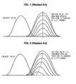
- FIG. 1 is a view illustrating a lift changing property of a CVVL system having no self-advanced/delayed angle function.
- FIG. 2 is a view illustrating a lift changing property of a CVVL system having a self-advanced/delayed angle function.
- FIGS. 1 and 2 show the change in suction valve lift profile at a valve lift variation according to the presence or absence of the self-advanced/delayed angle function.
- the CVVL system having no self-advanced/delayed angle function is a system in which the MOP is not changed by the operation of the CVVL mechanism when the valve lift is changed.
- the structure thereof is relatively simple, which is preferable to CVVL embodiment, but the cam timing is controlled by a separate CVVT system.
- the CVVL system having the self-advanced/delayed angle function is a system in which the MOP is changed by the operation of the CVVL mechanism when the valve lift is changed. If the advanced/delayed angle property of the CVVL mechanism is utilized, it can share a portion of separate CVVT operating necessity.
- a suction/exhaust cam timing is controlled to minimize a fuel consuming amount under driving conditions.
- a reference position is selected on the basis of the optimum cam timing in a low-speed and low-load region including start and idle, and generally corresponds to a suction/exhaust timing at which the value overlap is minimized.
- the reference position of the suction cam timing is the most delayed angle position, while the reference position of the exhaust cam timing is the most advanced angle position.
- the reference position should be maintained under a condition in which the oil pressure sufficient for driving the CVVT is not generated at start and low-speed driving.
- the optimum cam timing should be shifted in such a manner that the suction is shifted to the advanced angle direction and the exhaust timing is shifted to the delayed angle direction, in relation to the idle cam timing.
- the oil pressure created in a head oil gallery is respectively applied to the advanced angle chamber and the delayed angle chamber in the CVVT apparatus by an oil control valve (OCV) through two oil circuits (advanced angle oil passage and delayed angle oil passage).
- OCV oil control valve
- the CVVT is operated against the resilient force of the bias spring by the pressure difference between the advanced angle chamber and the delayed angle chamber.
- the suction/exhaust cam timing can be varied.
- the CVVT is not operated due to the lack of the oil pressure, and the suction/exhaust CVVT should be operated in the reference position (suction most delayed angle and exhaust most advanced angle).
- the fuel efficiency is deteriorated due to the increased pumping loss and the increased effective compression ratio.
- Various aspects of the present invention are directed to providing a continuously variable valve timing system and a method for controlling the same, which improves a method for controlling selection of a reference position of a CVVT (continuously variable valve timing) in a general Non-CVVL engine and a CVVL (continuously variable valve lift) engine when a general hydraulic CVVL system is employed in the CVVL engine having no self-advanced/delayed angle function, thereby reducing a pumping loss and thus improving a fuel efficiency and an effective compression ratio to improve a knock property and reduce variations of RPM in a cycle.
- CVVT continuously variable valve timing
- CVVL continuously variable valve lift
- a method for controlling a continuously variable valve timing (CVVT) system which is operated in cooperation with a continuously variable valve lift (CVVL) engine, including the steps of, setting a reference position of a suction CVVT to a most advanced angle position controlling a delayed angle amount at the reference position of the most advanced angle.
- CVVT continuously variable valve timing
- CVVL continuously variable valve lift
- the present invention can set a low valve lift and optimum cam timing, which is necessary for the same in a low RPM region including an idle condition, as a reference position. Therefore, the optimum valve lift can be used in the region without employing the CVVT control, thereby improving the fuel efficiency in the idle and low-speed region. In addition, a proper effective compression ratio is maintained to suppress generation of knock and decrease variations of RPM.
- the valve lift is changed, it is possible to improve the fuel efficiency at the low speed, without complicating the mechanism required to employ the CVVL mechanism having the self-advanced/delayed angle function and increasing rotational inertial and friction, as well as a cost.
- the combination of the valve lift and the cam timing optimized for various driving conditions can be achieved by using the general hydraulic CVVT module to improve a merchantable quality.
- FIG. 1 is a view illustrating a lift changing property of a CVVL system having no self-advanced/delayed angle function.
- FIG. 2 is a view illustrating a lift changing property of a CVVL system having a self-advanced/delayed angle function.
- FIG. 3 is a view illustrating the structure of a hydraulic CVVT system in the related art.
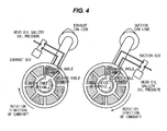
- FIG. 4 is a view illustrating the structure of a hydraulic CVVT system according to an exemplary embodiment of the present invention.
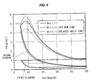
- FIG. 5 is a graph illustrating the efficiency based on a valve lift and a suction cam timing.
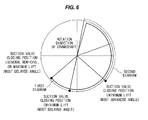
- FIG. 6 is a view illustrating an optimum valve lift and a suction timing in a continuously variable valve lift engine.
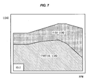
- FIG. 7 is a view illustrating the optimum valve lift and the suction timing for each driving condition.
- FIG. 8 is a view illustrating properties of the optimum valve lift and the suction timing.
- FIG. 9 is a view illustrating an effective compression ratio and a RAM variation according to a lift/suction cam.
- FIGS. 4 to 9 are views illustrating a continuously variable valve timing system and a method of controlling the same according to an exemplary embodiment of the present invention.
- FIG. 4 is a view illustrating the structure of a hydraulic CVVT system according to an exemplary embodiment of the present invention.
- FIG. 5 is a graph illustrating the efficiency based on a valve lift and a suction cam timing.
- FIG. 6 is a view illustrating an optimum valve lift and a suction timing in a continuously variable valve lift engine.
- FIG. 7 is a view illustrating the optimum valve lift and the suction timing for each driving condition.
- FIG. 8 is a view illustrating properties of the optimum valve lift and the suction timing.
- FIG. 9 is a view illustrating an effective compression ratio and a RAM variation according to a lift/suction cam.
- controlling a dimension of a valve lift continuously and variably is to minimize a pumping loss and thus improve a fuel efficiency. Since the valve lift and a valve opening duration can be variably controlled in the CVVL engine, the engine can be operated by selecting a suction valve opening position and a suction valve closing position to have an optimum value in cooperation with a CVVT mechanism.
- the pumping loss is theoretically zero to a piston position during a suction valve closing timing, the pumping loss is minimized by suctioning an air volume corresponding to a volume of a combustion chamber for the suction valve closing duration.
- the suction valve closing position is significantly shifted to an advanced angle in the general Non-CVVL engine having a constant valve lift and valve closing direction, the suction valve opening timing is significantly shifted to the advanced angle, and thus the valve overlap becomes excessively large, so that misfire occurs due to unstable combustion, which is a condition which cannot drive a vehicle.
- a first diagram indicates a combustion pressure and a volume at a maximum lift (valve lift which is equal to MP1)
- a second diagram indicates a combustion pressure and a volume at a minimum lift (throttle minimizing lift by a throttle body).
- the pumping loss in comparison to the pumping loss (area of a border portion of the first diagram) in the case of using the maximum lift, the pumping loss (area of red border portion) in the case of using the minimum lift is varied depending upon the minimum lift, but when the minimum lift is 1 mm, the pumping loss can be reduced by 1/3 of the Non-CVVL (or the maximum lift). It can reduce an indicated mean effective pressure (IMEP) and fuel consumption, thereby improving the fuel efficiency.
- IMEP mean effective pressure
- FIGS. 7 and 8 show the optimum valve lift and a suction timing property, in which the below engine driving property is obtained according to the lift and the suction cam.
- the pumping loss is minimized and the fuel efficiency is improved. If the lift is minimum and the suction cam is at the most delayed angle, the effective compression ratio is excessive, knocking occurs, and an RPM variation in the cycle is excessive. If the lift is maximum and the suction cam is the most advanced angle, the inner EGR is excessive, and the combustion stability is deteriorated. If the lift is maximum and the suction cam is at the most delayed angle, the high-speed output is increased.
- the minimum lift and the most advanced angle suction cam timing should be used.
- the suction cam timing is fixed to the most delayed angle condition. In this instance, the pumping loss can be reduced by using the maximum lift instead of the minimum lift, but the fuel efficiency is deteriorated in comparison with the minimum lift and the most advanced angle suction cam.
- the minimum lift and the most advanced angle suction cam timing are required in a partial-load region which is an important region, as well as the idle region. In this instance, as the load is increased, the lift is increased and the suction cam timing is slightly delayed.
- the CVVL engine having a self-advanced angle function has an effect of obtaining the advanced angle of the opening/closing timing and a valve profile through reduction of the lift, but the CVVL engine having no self-advanced angle function should have the optimum cam timing by the control and operation of the CVVT.
- the CVVT system capable of obtaining the optimum cam timing in the CVVL engine according to an exemplary embodiment of the present invention, and the method for controlling the same will be described.
- the optimum fuel efficiency, drivability and performance can be satisfied by simultaneously obtaining the optimum lift and cam timing for every engine driving region. It can be seen that CVVT requirements at the low speed are different from those of the general Non-CVVL engine.
- the present invention relates to the hydraulic control CVVT for driving the optimum cam timing for every valve lift in the CVVL engine having no self-advanced/delayed angle function or remarkably insufficient advanced/delayed angle amount, as compared with the necessary advanced/delayed angle amount, when the valve lift is varied.
- a reference position of the suction CVVT is set to the most advanced angle position, and a CVVT assembly with a bias spring to control the delayed angle amount at the reference position of the most advanced angle.
- the reference position of the suction CVVT in the CVVT system which operates in cooperation with the CVVL engine is set by the spring.
- the CVVT system In order to set the reference position of the suction CVVT to the most advanced angle position and control the delayed angle of the CVVT, the CVVT system is provided with the bias spring so that the suction cam timing is shifted in an advanced angle direction when an oil control valve installed in the CVVT system does not operate (when PWM is zero).
- the oil control valve installed in the CVVT system operates to the max (when PWM is applied)
- the cam timing is shifted to the advanced angle position by the resilience force of the bias spring.
- the position of the CVVT can be fixed by using a lock pin, like a general CVVT module. If the oil control valve is operated after the oil pressure is created, the oil pressure is applied to the delayed angle chamber of the CVVT module through the oil control valve and the oil circuit. The delayed angle chamber is connected to a drain passage through the oil control valve, and thus the cam timing is shifted in the advanced angle direction by the oil pressure difference in the advanced angle chamber and the delayed angle chamber.
- the reference position of the suction CVVT is set to the most advanced angle position in the CVVT system which is operated in cooperation with the CVVL engine. After that, the delayed angle amount is controlled at the reference position of the advanced angle to improve the fuel efficiency at the low speed and increase the merchantable quality.
Landscapes
- Engineering & Computer Science (AREA)
- Mechanical Engineering (AREA)
- General Engineering & Computer Science (AREA)
- Chemical & Material Sciences (AREA)
- Combustion & Propulsion (AREA)
- Valve Device For Special Equipments (AREA)
- Output Control And Ontrol Of Special Type Engine (AREA)
Abstract
Description
- The present application claims priority to Korean Patent Application No.
10-2011-0063011, filed on June 28, 2011 - The present invention relates to a continuously variable valve timing system and a method for controlling the same, and more particularly, to a continuously variable valve timing system and a method for controlling the same which can improve a fuel efficiency by controlling a reference position when a general hydraulic CVVT (continuously variable valve timing) system is employed in a continuously variable valve lift (CVVL) engine having no self-advanced/delayed angle function.
- In general, it is known in CVVL engines that a valve lift and valve opening duration is directly controlled by an electronic control unit (ECU) to improve fuel efficiency, performance and responsibility, and reduce emissions.
- A valve lift changing property of the CVVL system is varied depending upon the structure of the variable lift mechanism of the CVVL engine. In view of the engine control, the valve lift changing property can be divided into two types described below, depending upon whether the maximum opening point (MOP) is varied or not when the valve lift is changed.
-
FIG. 1 is a view illustrating a lift changing property of a CVVL system having no self-advanced/delayed angle function.FIG. 2 is a view illustrating a lift changing property of a CVVL system having a self-advanced/delayed angle function.FIGS. 1 and 2 show the change in suction valve lift profile at a valve lift variation according to the presence or absence of the self-advanced/delayed angle function. - The CVVL system having no self-advanced/delayed angle function is a system in which the MOP is not changed by the operation of the CVVL mechanism when the valve lift is changed. The structure thereof is relatively simple, which is preferable to CVVL embodiment, but the cam timing is controlled by a separate CVVT system. The CVVL system having the self-advanced/delayed angle function is a system in which the MOP is changed by the operation of the CVVL mechanism when the valve lift is changed. If the advanced/delayed angle property of the CVVL mechanism is utilized, it can share a portion of separate CVVT operating necessity.
- In addition, it is necessary to perform a cam timing control by monitoring a separate CVVT system to the CVVL engine having no self-advanced/delayed angle function. A conventional hydraulic CVVT system which is generally employed in a common Non-CVVL engine is used.
- In the hydraulic CVVT system for the Non-CVVL engine, since a fixed suction value lift is used in the Non-CVVL engine, a suction/exhaust cam timing is controlled to minimize a fuel consuming amount under driving conditions. In the case of the general Non-CVVL engine, a reference position is selected on the basis of the optimum cam timing in a low-speed and low-load region including start and idle, and generally corresponds to a suction/exhaust timing at which the value overlap is minimized.
- That is, the reference position of the suction cam timing is the most delayed angle position, while the reference position of the exhaust cam timing is the most advanced angle position. The reference position should be maintained under a condition in which the oil pressure sufficient for driving the CVVT is not generated at start and low-speed driving.
- In the CVVT, as shown in
FIG. 3 , if an outer sprocket rotates, an inner rotor rotates slower than the outer sprocket due to cam frictional torque, and thus the timing is always shifted to the most delayed angle position. In the case of the suction CVVT, the shifted position becomes the reference position, but in the case of the exhaust CVVT, a bias spring is installed between the sprocket and the inner rotor to forcefully shift the timing to the most advanced angle position, so that the most advanced angle position is maintained through the resilient force. If RMP is increased or the idle is increased as compared with the idle driving condition, the optimum cam timing should be shifted in such a manner that the suction is shifted to the advanced angle direction and the exhaust timing is shifted to the delayed angle direction, in relation to the idle cam timing. In this instance, the oil pressure created in a head oil gallery is respectively applied to the advanced angle chamber and the delayed angle chamber in the CVVT apparatus by an oil control valve (OCV) through two oil circuits (advanced angle oil passage and delayed angle oil passage). In the case of the cam frictional torque and the exhaust CVVT, the CVVT is operated against the resilient force of the bias spring by the pressure difference between the advanced angle chamber and the delayed angle chamber. - In the case of the hydraulic CVVT employed in general Non-CVVL engines, an oil pressure of a predetermined level or more should be obtained to operate the CVVT. Accordingly, since the stability and responsibility in the CVVT control is significantly deteriorated at the low speed (usually idle RPM) which cannot create the sufficient oil pressure in the Non-CVVL engine, the cam timing of the reference position (suction the most delayed angle position and the exhaust most advanced angle position) should be used as it is. Therefore, the cam timing is selected as the reference position, and the cam timing is controlled in such a manner that the suction is shifted in the advanced angle direction and the exhaust is shifted in the delayed angle direction, rather than the reference position, in the engine driving region except for the low-speed and low-load duration.
- However, in the case where the CVVT system for the Non-CVVL engine is employed in the CVVL engine having no self-advanced/delayed angle function, it is not possible to control the optimum cam timing, and thus there are some problems of reducing the fuel efficiency, generating knocking, decreasing vehicle responsibility, and vibrating the vehicle.
- That is, only when the RPM is increased to create the oil pressure sufficient to operate the CVVT, the suction/exhaust cam timing can be varied. However, in the low-speed duration the CVVT is not operated due to the lack of the oil pressure, and the suction/exhaust CVVT should be operated in the reference position (suction most delayed angle and exhaust most advanced angle). In the case of using the lowest delayed lift, there is another problem in that the fuel efficiency is deteriorated due to the increased pumping loss and the increased effective compression ratio.
- The information disclosed in this Background of the Invention section is only for enhancement of understanding of the general background of the invention and should not be taken as an acknowledgement or any form of suggestion that this information forms the prior art already known to a person skilled in the art.
- Various aspects of the present invention are directed to providing a continuously variable valve timing system and a method for controlling the same, which improves a method for controlling selection of a reference position of a CVVT (continuously variable valve timing) in a general Non-CVVL engine and a CVVL (continuously variable valve lift) engine when a general hydraulic CVVL system is employed in the CVVL engine having no self-advanced/delayed angle function, thereby reducing a pumping loss and thus improving a fuel efficiency and an effective compression ratio to improve a knock property and reduce variations of RPM in a cycle.
- In one aspect of the present invention, there is provided a method for controlling a continuously variable valve timing (CVVT) system which is operated in cooperation with a continuously variable valve lift (CVVL) engine, including the steps of, setting a reference position of a suction CVVT to a most advanced angle position controlling a delayed angle amount at the reference position of the most advanced angle.
- With the above configuration, the present invention can set a low valve lift and optimum cam timing, which is necessary for the same in a low RPM region including an idle condition, as a reference position. Therefore, the optimum valve lift can be used in the region without employing the CVVT control, thereby improving the fuel efficiency in the idle and low-speed region. In addition, a proper effective compression ratio is maintained to suppress generation of knock and decrease variations of RPM. When the valve lift is changed, it is possible to improve the fuel efficiency at the low speed, without complicating the mechanism required to employ the CVVL mechanism having the self-advanced/delayed angle function and increasing rotational inertial and friction, as well as a cost. Furthermore, as compared with the CVVL mechanism having the self advanced/delayed angle function, when a temperature of cooling water is low or atmosphere is low, the combination of the valve lift and the cam timing optimized for various driving conditions, such as full-load driving and costing driving, can be achieved by using the general hydraulic CVVT module to improve a merchantable quality.
- The methods and apparatuses of the present invention have other features and advantages which will be apparent from or are set forth in more detail in the accompanying drawings, which are incorporated herein, and the following Detailed Description, which together serve to explain certain principles of the present invention.
-
FIG. 1 is a view illustrating a lift changing property of a CVVL system having no self-advanced/delayed angle function. -
FIG. 2 is a view illustrating a lift changing property of a CVVL system having a self-advanced/delayed angle function. -
FIG. 3 is a view illustrating the structure of a hydraulic CVVT system in the related art. -
FIG. 4 is a view illustrating the structure of a hydraulic CVVT system according to an exemplary embodiment of the present invention. -
FIG. 5 is a graph illustrating the efficiency based on a valve lift and a suction cam timing. -
FIG. 6 is a view illustrating an optimum valve lift and a suction timing in a continuously variable valve lift engine. -
FIG. 7 is a view illustrating the optimum valve lift and the suction timing for each driving condition. -
FIG. 8 is a view illustrating properties of the optimum valve lift and the suction timing. -
FIG. 9 is a view illustrating an effective compression ratio and a RAM variation according to a lift/suction cam. - It should be understood that the appended drawings are not necessarily to scale, presenting a somewhat simplified representation of various features illustrative of the basic principles of the invention. The specific design features of the present invention as disclosed herein, including, for example, specific dimensions, orientations, locations, and shapes will be determined in part by the particular intended application and use environment.
- In the figures, reference numbers refer to the same or equivalent parts of the present invention throughout the several figures of the drawing.
- Reference will now be made in detail to various embodiments of the present invention(s), examples of which are illustrated in the accompanying drawings and described below. While the invention(s) will be described in conjunction with exemplary embodiments, it will be understood that the present description is not intended to limit the invention(s) to those exemplary embodiments. On the contrary, the invention(s) is/are intended to cover not only the exemplary embodiments, but also various alternatives, modifications, equivalents and other embodiments, which may be included within the spirit and scope of the invention as defined by the appended claims.
- Hereinafter, a preferred embodiment of the present invention will be described with reference to the accompanying drawings. In the entire description of the present invention, the same drawing reference numerals are used for the same elements across various figures.
-
FIGS. 4 to 9 are views illustrating a continuously variable valve timing system and a method of controlling the same according to an exemplary embodiment of the present invention.FIG. 4 is a view illustrating the structure of a hydraulic CVVT system according to an exemplary embodiment of the present invention.FIG. 5 is a graph illustrating the efficiency based on a valve lift and a suction cam timing.FIG. 6 is a view illustrating an optimum valve lift and a suction timing in a continuously variable valve lift engine. - In addition,
FIG. 7 is a view illustrating the optimum valve lift and the suction timing for each driving condition.FIG. 8 is a view illustrating properties of the optimum valve lift and the suction timing.FIG. 9 is a view illustrating an effective compression ratio and a RAM variation according to a lift/suction cam. - In a CVVL engine, controlling a dimension of a valve lift continuously and variably is to minimize a pumping loss and thus improve a fuel efficiency. Since the valve lift and a valve opening duration can be variably controlled in the CVVL engine, the engine can be operated by selecting a suction valve opening position and a suction valve closing position to have an optimum value in cooperation with a CVVT mechanism.
- As shown in
FIGS. 5 and6 , if the suction valve closing timing is significantly shifted to an advanced angle, the air confined in a combustion chamber is adiabatically expanded to a bottom dead center (BDC), and then is subjected to adiabatic compression as a piston is raised. - In this instance, since the pumping loss is theoretically zero to a piston position during a suction valve closing timing, the pumping loss is minimized by suctioning an air volume corresponding to a volume of a combustion chamber for the suction valve closing duration. Meanwhile, in the case where the suction valve closing position is significantly shifted to an advanced angle in the general Non-CVVL engine having a constant valve lift and valve closing direction, the suction valve opening timing is significantly shifted to the advanced angle, and thus the valve overlap becomes excessively large, so that misfire occurs due to unstable combustion, which is a condition which cannot drive a vehicle.
- Meanwhile, in
FIG. 5 , a first diagram indicates a combustion pressure and a volume at a maximum lift (valve lift which is equal to MP1), and a second diagram indicates a combustion pressure and a volume at a minimum lift (throttle minimizing lift by a throttle body). - In comparison to the pumping loss (area of a border portion of the first diagram) in the case of using the maximum lift, the pumping loss (area of red border portion) in the case of using the minimum lift is varied depending upon the minimum lift, but when the minimum lift is 1 mm, the pumping loss can be reduced by 1/3 of the Non-CVVL (or the maximum lift). It can reduce an indicated mean effective pressure (IMEP) and fuel consumption, thereby improving the fuel efficiency.
-
FIGS. 7 and8 show the optimum valve lift and a suction timing property, in which the below engine driving property is obtained according to the lift and the suction cam. - First, if the lift is minimum and the suction cam is the most advanced angle, the pumping loss is minimized and the fuel efficiency is improved. If the lift is minimum and the suction cam is at the most delayed angle, the effective compression ratio is excessive, knocking occurs, and an RPM variation in the cycle is excessive. If the lift is maximum and the suction cam is the most advanced angle, the inner EGR is excessive, and the combustion stability is deteriorated. If the lift is maximum and the suction cam is at the most delayed angle, the high-speed output is increased.
- The properties of the continuously variable valve timing for each load region will now be described.
- Since the fuel efficiency is important in the idle region including a low speed and a low load, the minimum lift and the most advanced angle suction cam timing should be used. In the engine equipped with the oil pump and the CVVT system for a general Non-CVVL, since the oil pressure sufficient to operate the CVVT is not created due to the low RPM, the suction cam timing is fixed to the most delayed angle condition. In this instance, the pumping loss can be reduced by using the maximum lift instead of the minimum lift, but the fuel efficiency is deteriorated in comparison with the minimum lift and the most advanced angle suction cam.
- With reference to the idle silence, a torque difference required for the compression process according to the effective compression ratio occurs, and thus there is a difference in the RPM variation properties within a cycle. In general, if the effective compression ratio is lowered at the idle driving, the RPM variation is decreased to improve the idle silence. Accordingly, as shown in
FIG. 9 , it can be known that the minimum lift and the most advanced angle condition which lowers the effective compression ratio are advantageous in order to reduce the idle RPM variation. - The minimum lift and the most advanced angle suction cam timing are required in a partial-load region which is an important region, as well as the idle region. In this instance, as the load is increased, the lift is increased and the suction cam timing is slightly delayed.
- In the full-load region, it is important to improve a torque by suction the maximum air volume at the full load, and thus a lift capable of obtaining the maximum air volume, and a cam timing at that time are selected. In general, 60% to 80T of the maximum lift at low and middle speed is used, and the maximum lift is used at the high speed.
- Since there are the suction valve lift and the suction valve timing which can maximize the fuel efficiency and the combustion stability depending upon the driving condition, the CVVL engine having a self-advanced angle function has an effect of obtaining the advanced angle of the opening/closing timing and a valve profile through reduction of the lift, but the CVVL engine having no self-advanced angle function should have the optimum cam timing by the control and operation of the CVVT.
- The CVVT system capable of obtaining the optimum cam timing in the CVVL engine according to an exemplary embodiment of the present invention, and the method for controlling the same will be described.
- As described above, the optimum fuel efficiency, drivability and performance can be satisfied by simultaneously obtaining the optimum lift and cam timing for every engine driving region. It can be seen that CVVT requirements at the low speed are different from those of the general Non-CVVL engine.
- Therefore, the present invention relates to the hydraulic control CVVT for driving the optimum cam timing for every valve lift in the CVVL engine having no self-advanced/delayed angle function or remarkably insufficient advanced/delayed angle amount, as compared with the necessary advanced/delayed angle amount, when the valve lift is varied. A reference position of the suction CVVT is set to the most advanced angle position, and a CVVT assembly with a bias spring to control the delayed angle amount at the reference position of the most advanced angle.
- According to an exemplary embodiment of the present invention, the reference position of the suction CVVT in the CVVT system which operates in cooperation with the CVVL engine is set by the spring.
- In order to set the reference position of the suction CVVT to the most advanced angle position and control the delayed angle of the CVVT, the CVVT system is provided with the bias spring so that the suction cam timing is shifted in an advanced angle direction when an oil control valve installed in the CVVT system does not operate (when PWM is zero). In the case where the oil control valve installed in the CVVT system operates to the max (when PWM is applied), it is preferable that the oil control valve changes an oil pressure passage connected to the CVVT system to change an oil circuit in a head or an oil passage in a cam shaft.
- As described above, in the state in which the oil control valve does not operate or the head oil pressure is not sufficient at the low speed, since the oil pressure is not applied to the advanced angle chamber and the delayed angle chamber in the CVVT module, the cam timing is shifted to the advanced angle position by the resilience force of the bias spring.
- The position of the CVVT can be fixed by using a lock pin, like a general CVVT module. If the oil control valve is operated after the oil pressure is created, the oil pressure is applied to the delayed angle chamber of the CVVT module through the oil control valve and the oil circuit. The delayed angle chamber is connected to a drain passage through the oil control valve, and thus the cam timing is shifted in the advanced angle direction by the oil pressure difference in the advanced angle chamber and the delayed angle chamber.
- With the continuously variable valve timing system and the control method according to an exemplary embodiment of the present invention, the reference position of the suction CVVT is set to the most advanced angle position in the CVVT system which is operated in cooperation with the CVVL engine. After that, the delayed angle amount is controlled at the reference position of the advanced angle to improve the fuel efficiency at the low speed and increase the merchantable quality.
- The foregoing descriptions of specific exemplary embodiments of the present invention have been presented for purposes of illustration and description. They are not intended to be exhaustive or to limit the invention to the precise forms disclosed, and obviously many modifications and variations are possible in light of the above teachings. The exemplary embodiments were chosen and described in order to explain certain principles of the invention and their practical application, to thereby enable others skilled in the art to make and utilize various exemplary embodiments of the present invention, as well as various alternatives and modifications thereof. It is intended that the scope of the invention be defined by the Claims appended hereto and their equivalents.
Claims (5)
- A continuously variable valve timing (CVVT) system which is operated in cooperation with a continuously variable valve lift (CVVL) engine, wherein a reference position of a suction CVVT is set by a spring.
- The continuously variable valve timing (CVVT) system of claim 1, wherein the spring is adapted such that a suction cam timing is shifted in an advanced angle direction when an oil control valve installed in the CVVT system does not operate.
- A method for controlling a continuously variable valve timing (CVVT) system which is operated in cooperation with a continuously variable valve lift (CVVL) engine, comprising the steps of:setting a reference position of a suction CVVT to a most advanced angle position; andcontrolling a delayed angle amount at the reference position of the most advanced angle.
- The method according to claim 3, wherein when an oil control valve installed in the CVVT system does not operate, a suction cam timing is shift in an advanced angle direction by a bias spring which is installed in the CVVT system.
- The method according to claim 3, wherein when the oil control valve installed in the CVVT system operates to the max, the oil control valve changes an oil pressure passage connected to the CVVT system.
Applications Claiming Priority (1)
| Application Number | Priority Date | Filing Date | Title |
|---|---|---|---|
| KR1020110063011A KR101262532B1 (en) | 2011-06-28 | 2011-06-28 | Continuously Variable Valve Lift system and controlling method |
Publications (2)
| Publication Number | Publication Date |
|---|---|
| EP2540997A1 true EP2540997A1 (en) | 2013-01-02 |
| EP2540997B1 EP2540997B1 (en) | 2015-10-07 |
Family
ID=46146655
Family Applications (1)
| Application Number | Title | Priority Date | Filing Date |
|---|---|---|---|
| EP12167237.2A Not-in-force EP2540997B1 (en) | 2011-06-28 | 2012-05-09 | Continuously variable valve timing system and method for controlling the same |
Country Status (3)
| Country | Link |
|---|---|
| US (1) | US20130000575A1 (en) |
| EP (1) | EP2540997B1 (en) |
| KR (1) | KR101262532B1 (en) |
Families Citing this family (5)
| Publication number | Priority date | Publication date | Assignee | Title |
|---|---|---|---|---|
| KR101448794B1 (en) | 2013-07-02 | 2014-10-08 | 현대자동차 주식회사 | Method of controlling CVVT according to current control for oil control valve |
| KR101558352B1 (en) | 2013-10-14 | 2015-10-07 | 현대자동차 주식회사 | Engine having continuous varialbe valve timing device |
| US20160363010A1 (en) | 2015-06-09 | 2016-12-15 | Hyundai Motor Company | Method of controlling intermediate phase cvvt |
| US9617925B2 (en) * | 2015-07-07 | 2017-04-11 | Hyundai Motor Company | Control method using continuous variable valve duration apparatus |
| KR102417382B1 (en) * | 2016-12-14 | 2022-07-06 | 현대자동차주식회사 | Method for controlling valve timing and valve duration using variable valve timimg apparatus and continuously variable valve dulation apparatus |
Citations (2)
| Publication number | Priority date | Publication date | Assignee | Title |
|---|---|---|---|---|
| US20100050965A1 (en) * | 2008-09-01 | 2010-03-04 | Hitachi Automative Systems, Ltd. | Variable valve control apparatus |
| US20100116231A1 (en) * | 2008-11-12 | 2010-05-13 | Hitoshi Toda | Variable valve gear for internal combustion engine |
Family Cites Families (4)
| Publication number | Priority date | Publication date | Assignee | Title |
|---|---|---|---|---|
| JP2006307656A (en) * | 2005-04-26 | 2006-11-09 | Hitachi Ltd | Variable valve system for compression ignition engine |
| JP2008088928A (en) * | 2006-10-04 | 2008-04-17 | Toyota Motor Corp | Variable valve timing control device for internal combustion engine |
| JP4858729B2 (en) * | 2008-11-12 | 2012-01-18 | 三菱自動車工業株式会社 | Variable valve gear |
| JP4725655B2 (en) | 2009-02-09 | 2011-07-13 | 株式会社デンソー | Valve timing adjustment device |
-
2011
- 2011-06-28 KR KR1020110063011A patent/KR101262532B1/en not_active Expired - Fee Related
- 2011-12-29 US US13/339,832 patent/US20130000575A1/en not_active Abandoned
-
2012
- 2012-05-09 EP EP12167237.2A patent/EP2540997B1/en not_active Not-in-force
Patent Citations (2)
| Publication number | Priority date | Publication date | Assignee | Title |
|---|---|---|---|---|
| US20100050965A1 (en) * | 2008-09-01 | 2010-03-04 | Hitachi Automative Systems, Ltd. | Variable valve control apparatus |
| US20100116231A1 (en) * | 2008-11-12 | 2010-05-13 | Hitoshi Toda | Variable valve gear for internal combustion engine |
Also Published As
| Publication number | Publication date |
|---|---|
| KR20130002029A (en) | 2013-01-07 |
| US20130000575A1 (en) | 2013-01-03 |
| KR101262532B1 (en) | 2013-05-08 |
| EP2540997B1 (en) | 2015-10-07 |
Similar Documents
| Publication | Publication Date | Title |
|---|---|---|
| KR101396736B1 (en) | Internal combustion engine with variable valve gear | |
| US6840201B2 (en) | Variable valve timing control apparatus and method for an internal combustion engine | |
| JP4858729B2 (en) | Variable valve gear | |
| EP2540997B1 (en) | Continuously variable valve timing system and method for controlling the same | |
| US10697378B2 (en) | Control system of miller cycle engine and method of controlling miller cycle engine | |
| KR101204558B1 (en) | Variable valve device for internal combustion engine | |
| JP4661461B2 (en) | Internal combustion engine with variable compression ratio mechanism | |
| US8635988B2 (en) | Variable valve device for internal combustion engine | |
| EP1886008B1 (en) | Control apparatus for internal combustion engine | |
| JP4506414B2 (en) | Valve characteristic control device for internal combustion engine | |
| JP4049092B2 (en) | Valve gear | |
| JP4389555B2 (en) | Control device for variable compression ratio internal combustion engine | |
| US20140165959A1 (en) | Engine having variable valve timing device and variable tumble device | |
| JP4696946B2 (en) | Engine intake control device | |
| JP2009216035A (en) | Control device of internal combustion engine | |
| JP2007218114A5 (en) | ||
| JP2009150320A (en) | Variable valve system for internal combustion engine | |
| JP4640120B2 (en) | Control device for internal combustion engine | |
| KR101136704B1 (en) | Variable valve driving device of internal combustion engine | |
| JP2005220754A (en) | Internal combustion engine with variable compression ratio mechanism | |
| JP2006046285A (en) | Intake control device for internal combustion engine | |
| JP2007056796A (en) | Internal combustion engine with variable compression ratio mechanism | |
| JP5088044B2 (en) | Engine control device | |
| JP2007162664A (en) | Variable valve operating angle control device for internal combustion engine | |
| JP2005090299A (en) | Internal combustion engine with variable compression ratio mechanism |
Legal Events
| Date | Code | Title | Description |
|---|---|---|---|
| PUAI | Public reference made under article 153(3) epc to a published international application that has entered the european phase |
Free format text: ORIGINAL CODE: 0009012 |
|
| AK | Designated contracting states |
Kind code of ref document: A1 Designated state(s): AL AT BE BG CH CY CZ DE DK EE ES FI FR GB GR HR HU IE IS IT LI LT LU LV MC MK MT NL NO PL PT RO RS SE SI SK SM TR |
|
| AX | Request for extension of the european patent |
Extension state: BA ME |
|
| 17P | Request for examination filed |
Effective date: 20130507 |
|
| RBV | Designated contracting states (corrected) |
Designated state(s): AL AT BE BG CH CY CZ DE DK EE ES FI FR GB GR HR HU IE IS IT LI LT LU LV MC MK MT NL NO PL PT RO RS SE SI SK SM TR |
|
| 17Q | First examination report despatched |
Effective date: 20140110 |
|
| GRAP | Despatch of communication of intention to grant a patent |
Free format text: ORIGINAL CODE: EPIDOSNIGR1 |
|
| INTG | Intention to grant announced |
Effective date: 20150416 |
|
| GRAS | Grant fee paid |
Free format text: ORIGINAL CODE: EPIDOSNIGR3 |
|
| GRAA | (expected) grant |
Free format text: ORIGINAL CODE: 0009210 |
|
| AK | Designated contracting states |
Kind code of ref document: B1 Designated state(s): AL AT BE BG CH CY CZ DE DK EE ES FI FR GB GR HR HU IE IS IT LI LT LU LV MC MK MT NL NO PL PT RO RS SE SI SK SM TR |
|
| REG | Reference to a national code |
Ref country code: GB Ref legal event code: FG4D |
|
| REG | Reference to a national code |
Ref country code: AT Ref legal event code: REF Ref document number: 753899 Country of ref document: AT Kind code of ref document: T Effective date: 20151015 Ref country code: CH Ref legal event code: EP |
|
| REG | Reference to a national code |
Ref country code: IE Ref legal event code: FG4D |
|
| REG | Reference to a national code |
Ref country code: DE Ref legal event code: R096 Ref document number: 602012011269 Country of ref document: DE |
|
| REG | Reference to a national code |
Ref country code: NL Ref legal event code: MP Effective date: 20151007 |
|
| REG | Reference to a national code |
Ref country code: AT Ref legal event code: MK05 Ref document number: 753899 Country of ref document: AT Kind code of ref document: T Effective date: 20151007 |
|
| REG | Reference to a national code |
Ref country code: LT Ref legal event code: MG4D |
|
| REG | Reference to a national code |
Ref country code: FR Ref legal event code: PLFP Year of fee payment: 5 |
|
| PG25 | Lapsed in a contracting state [announced via postgrant information from national office to epo] |
Ref country code: HR Free format text: LAPSE BECAUSE OF FAILURE TO SUBMIT A TRANSLATION OF THE DESCRIPTION OR TO PAY THE FEE WITHIN THE PRESCRIBED TIME-LIMIT Effective date: 20151007 Ref country code: NO Free format text: LAPSE BECAUSE OF FAILURE TO SUBMIT A TRANSLATION OF THE DESCRIPTION OR TO PAY THE FEE WITHIN THE PRESCRIBED TIME-LIMIT Effective date: 20160107 Ref country code: IT Free format text: LAPSE BECAUSE OF FAILURE TO SUBMIT A TRANSLATION OF THE DESCRIPTION OR TO PAY THE FEE WITHIN THE PRESCRIBED TIME-LIMIT Effective date: 20151007 Ref country code: NL Free format text: LAPSE BECAUSE OF FAILURE TO SUBMIT A TRANSLATION OF THE DESCRIPTION OR TO PAY THE FEE WITHIN THE PRESCRIBED TIME-LIMIT Effective date: 20151007 Ref country code: LT Free format text: LAPSE BECAUSE OF FAILURE TO SUBMIT A TRANSLATION OF THE DESCRIPTION OR TO PAY THE FEE WITHIN THE PRESCRIBED TIME-LIMIT Effective date: 20151007 Ref country code: ES Free format text: LAPSE BECAUSE OF FAILURE TO SUBMIT A TRANSLATION OF THE DESCRIPTION OR TO PAY THE FEE WITHIN THE PRESCRIBED TIME-LIMIT Effective date: 20151007 Ref country code: IS Free format text: LAPSE BECAUSE OF FAILURE TO SUBMIT A TRANSLATION OF THE DESCRIPTION OR TO PAY THE FEE WITHIN THE PRESCRIBED TIME-LIMIT Effective date: 20160207 |
|
| PG25 | Lapsed in a contracting state [announced via postgrant information from national office to epo] |
Ref country code: RS Free format text: LAPSE BECAUSE OF FAILURE TO SUBMIT A TRANSLATION OF THE DESCRIPTION OR TO PAY THE FEE WITHIN THE PRESCRIBED TIME-LIMIT Effective date: 20151007 Ref country code: AT Free format text: LAPSE BECAUSE OF FAILURE TO SUBMIT A TRANSLATION OF THE DESCRIPTION OR TO PAY THE FEE WITHIN THE PRESCRIBED TIME-LIMIT Effective date: 20151007 Ref country code: LV Free format text: LAPSE BECAUSE OF FAILURE TO SUBMIT A TRANSLATION OF THE DESCRIPTION OR TO PAY THE FEE WITHIN THE PRESCRIBED TIME-LIMIT Effective date: 20151007 Ref country code: SE Free format text: LAPSE BECAUSE OF FAILURE TO SUBMIT A TRANSLATION OF THE DESCRIPTION OR TO PAY THE FEE WITHIN THE PRESCRIBED TIME-LIMIT Effective date: 20151007 Ref country code: GR Free format text: LAPSE BECAUSE OF FAILURE TO SUBMIT A TRANSLATION OF THE DESCRIPTION OR TO PAY THE FEE WITHIN THE PRESCRIBED TIME-LIMIT Effective date: 20160108 Ref country code: PL Free format text: LAPSE BECAUSE OF FAILURE TO SUBMIT A TRANSLATION OF THE DESCRIPTION OR TO PAY THE FEE WITHIN THE PRESCRIBED TIME-LIMIT Effective date: 20151007 Ref country code: PT Free format text: LAPSE BECAUSE OF FAILURE TO SUBMIT A TRANSLATION OF THE DESCRIPTION OR TO PAY THE FEE WITHIN THE PRESCRIBED TIME-LIMIT Effective date: 20160208 Ref country code: FI Free format text: LAPSE BECAUSE OF FAILURE TO SUBMIT A TRANSLATION OF THE DESCRIPTION OR TO PAY THE FEE WITHIN THE PRESCRIBED TIME-LIMIT Effective date: 20151007 |
|
| REG | Reference to a national code |
Ref country code: DE Ref legal event code: R097 Ref document number: 602012011269 Country of ref document: DE |
|
| PG25 | Lapsed in a contracting state [announced via postgrant information from national office to epo] |
Ref country code: CZ Free format text: LAPSE BECAUSE OF FAILURE TO SUBMIT A TRANSLATION OF THE DESCRIPTION OR TO PAY THE FEE WITHIN THE PRESCRIBED TIME-LIMIT Effective date: 20151007 |
|
| PLBE | No opposition filed within time limit |
Free format text: ORIGINAL CODE: 0009261 |
|
| STAA | Information on the status of an ep patent application or granted ep patent |
Free format text: STATUS: NO OPPOSITION FILED WITHIN TIME LIMIT |
|
| PG25 | Lapsed in a contracting state [announced via postgrant information from national office to epo] |
Ref country code: EE Free format text: LAPSE BECAUSE OF FAILURE TO SUBMIT A TRANSLATION OF THE DESCRIPTION OR TO PAY THE FEE WITHIN THE PRESCRIBED TIME-LIMIT Effective date: 20151007 Ref country code: BE Free format text: LAPSE BECAUSE OF NON-PAYMENT OF DUE FEES Effective date: 20160531 Ref country code: SK Free format text: LAPSE BECAUSE OF FAILURE TO SUBMIT A TRANSLATION OF THE DESCRIPTION OR TO PAY THE FEE WITHIN THE PRESCRIBED TIME-LIMIT Effective date: 20151007 Ref country code: SM Free format text: LAPSE BECAUSE OF FAILURE TO SUBMIT A TRANSLATION OF THE DESCRIPTION OR TO PAY THE FEE WITHIN THE PRESCRIBED TIME-LIMIT Effective date: 20151007 Ref country code: DK Free format text: LAPSE BECAUSE OF FAILURE TO SUBMIT A TRANSLATION OF THE DESCRIPTION OR TO PAY THE FEE WITHIN THE PRESCRIBED TIME-LIMIT Effective date: 20151007 Ref country code: RO Free format text: LAPSE BECAUSE OF FAILURE TO SUBMIT A TRANSLATION OF THE DESCRIPTION OR TO PAY THE FEE WITHIN THE PRESCRIBED TIME-LIMIT Effective date: 20151007 |
|
| 26N | No opposition filed |
Effective date: 20160708 |
|
| PG25 | Lapsed in a contracting state [announced via postgrant information from national office to epo] |
Ref country code: SI Free format text: LAPSE BECAUSE OF FAILURE TO SUBMIT A TRANSLATION OF THE DESCRIPTION OR TO PAY THE FEE WITHIN THE PRESCRIBED TIME-LIMIT Effective date: 20151007 |
|
| PG25 | Lapsed in a contracting state [announced via postgrant information from national office to epo] |
Ref country code: BE Free format text: LAPSE BECAUSE OF FAILURE TO SUBMIT A TRANSLATION OF THE DESCRIPTION OR TO PAY THE FEE WITHIN THE PRESCRIBED TIME-LIMIT Effective date: 20151007 Ref country code: LU Free format text: LAPSE BECAUSE OF FAILURE TO SUBMIT A TRANSLATION OF THE DESCRIPTION OR TO PAY THE FEE WITHIN THE PRESCRIBED TIME-LIMIT Effective date: 20160509 |
|
| REG | Reference to a national code |
Ref country code: CH Ref legal event code: PL |
|
| PG25 | Lapsed in a contracting state [announced via postgrant information from national office to epo] |
Ref country code: LI Free format text: LAPSE BECAUSE OF NON-PAYMENT OF DUE FEES Effective date: 20160531 Ref country code: CH Free format text: LAPSE BECAUSE OF NON-PAYMENT OF DUE FEES Effective date: 20160531 |
|
| REG | Reference to a national code |
Ref country code: IE Ref legal event code: MM4A |
|
| REG | Reference to a national code |
Ref country code: FR Ref legal event code: PLFP Year of fee payment: 6 |
|
| PG25 | Lapsed in a contracting state [announced via postgrant information from national office to epo] |
Ref country code: IE Free format text: LAPSE BECAUSE OF NON-PAYMENT OF DUE FEES Effective date: 20160509 |
|
| REG | Reference to a national code |
Ref country code: FR Ref legal event code: PLFP Year of fee payment: 7 |
|
| PG25 | Lapsed in a contracting state [announced via postgrant information from national office to epo] |
Ref country code: CY Free format text: LAPSE BECAUSE OF FAILURE TO SUBMIT A TRANSLATION OF THE DESCRIPTION OR TO PAY THE FEE WITHIN THE PRESCRIBED TIME-LIMIT Effective date: 20151007 Ref country code: HU Free format text: LAPSE BECAUSE OF FAILURE TO SUBMIT A TRANSLATION OF THE DESCRIPTION OR TO PAY THE FEE WITHIN THE PRESCRIBED TIME-LIMIT; INVALID AB INITIO Effective date: 20120509 |
|
| PG25 | Lapsed in a contracting state [announced via postgrant information from national office to epo] |
Ref country code: MK Free format text: LAPSE BECAUSE OF FAILURE TO SUBMIT A TRANSLATION OF THE DESCRIPTION OR TO PAY THE FEE WITHIN THE PRESCRIBED TIME-LIMIT Effective date: 20151007 Ref country code: MT Free format text: LAPSE BECAUSE OF NON-PAYMENT OF DUE FEES Effective date: 20160531 Ref country code: TR Free format text: LAPSE BECAUSE OF FAILURE TO SUBMIT A TRANSLATION OF THE DESCRIPTION OR TO PAY THE FEE WITHIN THE PRESCRIBED TIME-LIMIT Effective date: 20151007 Ref country code: MC Free format text: LAPSE BECAUSE OF FAILURE TO SUBMIT A TRANSLATION OF THE DESCRIPTION OR TO PAY THE FEE WITHIN THE PRESCRIBED TIME-LIMIT Effective date: 20151007 |
|
| PG25 | Lapsed in a contracting state [announced via postgrant information from national office to epo] |
Ref country code: BG Free format text: LAPSE BECAUSE OF FAILURE TO SUBMIT A TRANSLATION OF THE DESCRIPTION OR TO PAY THE FEE WITHIN THE PRESCRIBED TIME-LIMIT Effective date: 20151007 |
|
| PG25 | Lapsed in a contracting state [announced via postgrant information from national office to epo] |
Ref country code: AL Free format text: LAPSE BECAUSE OF FAILURE TO SUBMIT A TRANSLATION OF THE DESCRIPTION OR TO PAY THE FEE WITHIN THE PRESCRIBED TIME-LIMIT Effective date: 20151007 |
|
| P01 | Opt-out of the competence of the unified patent court (upc) registered |
Effective date: 20230523 |
|
| PGFP | Annual fee paid to national office [announced via postgrant information from national office to epo] |
Ref country code: FR Payment date: 20230420 Year of fee payment: 12 Ref country code: DE Payment date: 20230420 Year of fee payment: 12 |
|
| PGFP | Annual fee paid to national office [announced via postgrant information from national office to epo] |
Ref country code: GB Payment date: 20230420 Year of fee payment: 12 |
|
| REG | Reference to a national code |
Ref country code: DE Ref legal event code: R119 Ref document number: 602012011269 Country of ref document: DE |
|
| GBPC | Gb: european patent ceased through non-payment of renewal fee |
Effective date: 20240509 |
|
| PG25 | Lapsed in a contracting state [announced via postgrant information from national office to epo] |
Ref country code: DE Free format text: LAPSE BECAUSE OF NON-PAYMENT OF DUE FEES Effective date: 20241203 |
|
| PG25 | Lapsed in a contracting state [announced via postgrant information from national office to epo] |
Ref country code: FR Free format text: LAPSE BECAUSE OF NON-PAYMENT OF DUE FEES Effective date: 20240531 |
|
| PG25 | Lapsed in a contracting state [announced via postgrant information from national office to epo] |
Ref country code: GB Free format text: LAPSE BECAUSE OF NON-PAYMENT OF DUE FEES Effective date: 20240509 |