EP2540627A1 - Aseptic filling system with online adding of particles - Google Patents
Aseptic filling system with online adding of particles Download PDFInfo
- Publication number
- EP2540627A1 EP2540627A1 EP20110746844 EP11746844A EP2540627A1 EP 2540627 A1 EP2540627 A1 EP 2540627A1 EP 20110746844 EP20110746844 EP 20110746844 EP 11746844 A EP11746844 A EP 11746844A EP 2540627 A1 EP2540627 A1 EP 2540627A1
- Authority
- EP
- European Patent Office
- Prior art keywords
- filling system
- segment
- particle adding
- line particle
- sterile filling
- Prior art date
- Legal status (The legal status is an assumption and is not a legal conclusion. Google has not performed a legal analysis and makes no representation as to the accuracy of the status listed.)
- Withdrawn
Links
Images




Classifications
-
- B—PERFORMING OPERATIONS; TRANSPORTING
- B65—CONVEYING; PACKING; STORING; HANDLING THIN OR FILAMENTARY MATERIAL
- B65B—MACHINES, APPARATUS OR DEVICES FOR, OR METHODS OF, PACKAGING ARTICLES OR MATERIALS; UNPACKING
- B65B55/00—Preserving, protecting or purifying packages or package contents in association with packaging
- B65B55/02—Sterilising, e.g. of complete packages
- B65B55/12—Sterilising contents prior to, or during, packaging
- B65B55/18—Sterilising contents prior to, or during, packaging by liquids or gases
-
- B—PERFORMING OPERATIONS; TRANSPORTING
- B01—PHYSICAL OR CHEMICAL PROCESSES OR APPARATUS IN GENERAL
- B01F—MIXING, e.g. DISSOLVING, EMULSIFYING OR DISPERSING
- B01F23/00—Mixing according to the phases to be mixed, e.g. dispersing or emulsifying
- B01F23/40—Mixing liquids with liquids; Emulsifying
- B01F23/45—Mixing liquids with liquids; Emulsifying using flow mixing
- B01F23/451—Mixing liquids with liquids; Emulsifying using flow mixing by injecting one liquid into another
-
- B—PERFORMING OPERATIONS; TRANSPORTING
- B01—PHYSICAL OR CHEMICAL PROCESSES OR APPARATUS IN GENERAL
- B01F—MIXING, e.g. DISSOLVING, EMULSIFYING OR DISPERSING
- B01F23/00—Mixing according to the phases to be mixed, e.g. dispersing or emulsifying
- B01F23/40—Mixing liquids with liquids; Emulsifying
- B01F23/45—Mixing liquids with liquids; Emulsifying using flow mixing
- B01F23/453—Mixing liquids with liquids; Emulsifying using flow mixing by moving the liquids in countercurrent
-
- B—PERFORMING OPERATIONS; TRANSPORTING
- B01—PHYSICAL OR CHEMICAL PROCESSES OR APPARATUS IN GENERAL
- B01F—MIXING, e.g. DISSOLVING, EMULSIFYING OR DISPERSING
- B01F25/00—Flow mixers; Mixers for falling materials, e.g. solid particles
- B01F25/70—Spray-mixers, e.g. for mixing intersecting sheets of material
- B01F25/72—Spray-mixers, e.g. for mixing intersecting sheets of material with nozzles
-
- B—PERFORMING OPERATIONS; TRANSPORTING
- B01—PHYSICAL OR CHEMICAL PROCESSES OR APPARATUS IN GENERAL
- B01F—MIXING, e.g. DISSOLVING, EMULSIFYING OR DISPERSING
- B01F35/00—Accessories for mixers; Auxiliary operations or auxiliary devices; Parts or details of general application
- B01F35/10—Maintenance of mixers
- B01F35/145—Washing or cleaning mixers not provided for in other groups in this subclass; Inhibiting build-up of material on machine parts using other means
- B01F35/146—Working under sterile conditions; Sterilizing the mixer or parts thereof
-
- B—PERFORMING OPERATIONS; TRANSPORTING
- B65—CONVEYING; PACKING; STORING; HANDLING THIN OR FILAMENTARY MATERIAL
- B65B—MACHINES, APPARATUS OR DEVICES FOR, OR METHODS OF, PACKAGING ARTICLES OR MATERIALS; UNPACKING
- B65B9/00—Enclosing successive articles, or quantities of material, e.g. liquids or semiliquids, in flat, folded, or tubular webs of flexible sheet material; Subdividing filled flexible tubes to form packages
- B65B9/10—Enclosing successive articles, or quantities of material, in preformed tubular webs, or in webs formed into tubes around filling nozzles, e.g. extruded tubular webs
- B65B9/12—Subdividing filled tubes to form two or more packages by sealing or securing involving displacement of contents
-
- B—PERFORMING OPERATIONS; TRANSPORTING
- B01—PHYSICAL OR CHEMICAL PROCESSES OR APPARATUS IN GENERAL
- B01F—MIXING, e.g. DISSOLVING, EMULSIFYING OR DISPERSING
- B01F2101/00—Mixing characterised by the nature of the mixed materials or by the application field
- B01F2101/06—Mixing of food ingredients
-
- B—PERFORMING OPERATIONS; TRANSPORTING
- B01—PHYSICAL OR CHEMICAL PROCESSES OR APPARATUS IN GENERAL
- B01F—MIXING, e.g. DISSOLVING, EMULSIFYING OR DISPERSING
- B01F2215/00—Auxiliary or complementary information in relation with mixing
- B01F2215/04—Technical information in relation with mixing
- B01F2215/0413—Numerical information
- B01F2215/0418—Geometrical information
- B01F2215/0431—Numerical size values, e.g. diameter of a hole or conduit, area, volume, length, width, or ratios thereof
-
- B—PERFORMING OPERATIONS; TRANSPORTING
- B65—CONVEYING; PACKING; STORING; HANDLING THIN OR FILAMENTARY MATERIAL
- B65B—MACHINES, APPARATUS OR DEVICES FOR, OR METHODS OF, PACKAGING ARTICLES OR MATERIALS; UNPACKING
- B65B2220/00—Specific aspects of the packaging operation
- B65B2220/14—Adding more than one type of material or article to the same package
-
- Y—GENERAL TAGGING OF NEW TECHNOLOGICAL DEVELOPMENTS; GENERAL TAGGING OF CROSS-SECTIONAL TECHNOLOGIES SPANNING OVER SEVERAL SECTIONS OF THE IPC; TECHNICAL SUBJECTS COVERED BY FORMER USPC CROSS-REFERENCE ART COLLECTIONS [XRACs] AND DIGESTS
- Y10—TECHNICAL SUBJECTS COVERED BY FORMER USPC
- Y10T—TECHNICAL SUBJECTS COVERED BY FORMER US CLASSIFICATION
- Y10T137/00—Fluid handling
- Y10T137/8593—Systems
- Y10T137/87571—Multiple inlet with single outlet
- Y10T137/87652—With means to promote mixing or combining of plural fluids
Definitions
- the present invention relates to a sterile filling system, and specifically relates to a sterile filling system for on-line particle adding.
- the existing sterile filling system such as Tetra Pak's sterile packaging technology, mainly comprises two parts, namely a filling part and a cleaning part.
- the liquid product A may be various liquid foods such as milk, fruit juice, soymilk, modulated milk, drink and the like, and a liquid product B may be various nutritive, special-flavoured liquid product, and the particles are solid.
- the finished product is required to be a sterile product.
- the present invention is intended to add particle on-line into the liquid product A, and ensure that a solid-liquid mixed product C is maintained in sterile state.
- a sterile filling system for on-line particle adding comprising a filling system, characterized in that it further comprises a system for on-line particle adding.
- the filling system comprises a first AP valve bank and an injection pipe, the first AP valve bank and the injection pipe being in connection with each other; and the system for on-line particle adding comprises a second AP valve bank, the second AP valve bank being in connection with the injection pipe.
- the filling system according to the present invention further comprises an on-line cleaning system.
- the cleaning system comprises an outer cleaning station and a plurality of reversible pipes, the reversible pipes being detachably connected to channels of the filling system and being capable of connecting to the outer cleaning station, the filling system, and the system for on-line particle adding in a reversible manner to form series connected cleaning pipeline.
- the solid-liquid mixed product C can be prepared by intensive mixing the liquid product A and liquid product B in the injection pipe, and finally a sterile packaging product can be formed by filling the solid-liquid mixed product C through the injection pipe into a molding unit, wherein the liquid product A is added to the injection pipe by the first AP valve bank, and the liquid product B is added to the injection pipe by the second AP valve bank.
- the packaging is required to be completed under sterile conditions in the whole process.
- the liquid product B is liquid, and it can be solidified immediately to form solid particles when it meets the liquid product A. According, the solid particles can be put into the liquid product an on-line by adding the liquid product B during production of the liquid product A and using the mixed characteristic of the two products so that a sterile solid-liquid mixing product C containing the solid particles is formed in a finished product.
- the principle of the present invention is that the liquid product A and the liquid product B are simultaneously delivered under sterility condition and then mixed in sterility environment to form the mixing product C containing the solid particles which will be filled into a sterile packaging material to form a sterile particle package.
- the liquid product A reached the first AP valve bank 11 is sterile
- the liquid product B reached the second AP valve bank 21 is sterile
- the sterile solid-liquid mixing product C containing the solid particles is formed by mixing the sterile liquid product A with the sterile liquid product B in a sterile state at the mixing nozzle 25.
- Each process of the production of the sterile solid-liquid mixing product C containing the solid particles is sterilized to achieve sterility.
- the sterilization methods mainly comprise hot air sterilization or hydrogen peroxide sterilization.
- the present invention comprises a filling system and a system for on-line particle adding.
- the present invention comprises an injection pipe 31, a first AP valve bank 11 (sterile product valve bank) and a second AP valve bank 21 (sterile product valve bank).
- the first AP valve bank 11 is in connection with the injection pipe 31 through a first flow control valve 12.
- the second AP valve bank 21 is in connection with the injection pipe 31 through a second flow control valve 22.
- the second flow control valve 22 is in connection with the injection pipe 31 through a second communicating pipe 26.
- a flow transducer 23 and a dosing valve 24 are disposed on the second communicating pipe 26, and a mixing nozzle 25 is disposed at the end of the second communicating pipe 26 and at the junction of the second communicating pipe 26 and the injection pipe 31.
- the mixing nozzle 25 is also in connected with the injection pipe 31.
- the first AP valve bank 11 is used to add the liquid product A into the injection pipe 31 while the second AP valve bank 21 is used to add the liquid product B into the injection pipe 31, and the liquid product A meets with the liquid product B at the mixing nozzle 25 to form particles in the injection pipe 31 so that the particles can be filled into the package at the molding unit 33 of the sterile solid-liquid mixing product C.
- the content ratio of the solid particles in the sterile solid-liquid mixing product C can be controlled precisely by controlling the first flow control valve 12 and the second flow control valve 22.
- the content ratio of the solid particles in the sterile solid-liquid mixing product C can be controlled precisely by controlling the first flow control valve 12, the second flow control valve 22, the flow transducer 23 and the dosing valve 24.
- the flow transducer 23 is used to monitor the flow of the liquid product B in the second communicating pipe 26.
- the working principle and function of the mixing nozzle 25 are that the liquid product B can be sprayed out from the through-holes 250 of the mixing nozzle 25 when the product pressure of the liquid product B is greater than that of the liquid product A so that the liquid product B meets the liquid product A and can be solidified immediately to form solid particles. According, the solid particles can be put into the liquid product an on-line by using the mixed characteristic of the two products, thereby a sterile solid-liquid mixing product C containing the solid particles is formed in the finished product.
- the present invention is desired to be sterilized to conduct the production in a sterile state.
- the sterilization methods mainly comprise hot air sterilization or hydrogen peroxide sterilization.
- the injection pipe 31 is disposed in the sterile tank 32.
- a method of series cleaning is used for the cleaning of the present invention, which comprises a cleaning pipeline which is in connection with the second AP valve bank 21, the first AP valve bank 11 and injection pipe 31 in turn.
- the cleaning solution travels from the outer cleaning station 42 to the second AP valve bank 21 through reversible pipe 43, and travels to the second AP valve bank 22, the flow transducer 23 (optional component) and the dosing valve 24 (optional component) in turn, then travels to the first AP valve bank 11 through the reversible pipes 45, 44, and then travels to the first flow control valve 12 and the injection pipe 31 in turn.
- the injection pipe 31 is in connection with the outer cleaning station 42 through the filling pipe 41.
- the cleaning circulation is finished after the cleaning solution travels out from the injection pipe 31 and back to the outer cleaning station 42 through the filling pipe 41.
- the cleaning solution is driven by standard cleaning solution provided by the outer cleaning station 42.
- the mixing nozzle is taken out to be cleaned manually during the cleaning. Accordingly, the system is cleaned effectively and thoroughly after the production.
- the cleaning pipeline achieves the clean-in-place (CIP) function of the present system with the aid of the existing pipes for production according to the present invention.
- CIP clean-in-place
- the filling pipe 41 herein has a function that it can be cleaned thoroughly by being inserted into the cleaning circuit during the cleaning, and then taken out after the cleaning is finished to connect to the injection pipe 31 to form a filling pipeline finally so that the filling liquid level of the solid-liquid mixed product C being controlled precisely can be monitored.
- a new cleaning pipeline can be formed by changing the connection of the pipes used for the production of the present invention by reversing the first reversible pipe 43, the second reversible pipe 44 and the third reversible pipe 45 as depicted in FIG. 3 only from bottom (dotted lines) to top (solid line) to connect with the corresponding cleaning pipeline.
- the first reversible pipe 43, the second reversible pipe 44 and the third reversible pipe 45 are detachably connected to the production pipeline.
- the cleaning according to the present invention can be achieved with the aid of the existing pipes for production according to the present invention without reconnection of independent cleaning pipeline, thereby improving productive efficiency and reducing equipment costs.
- the second AP valve bank 21 is in connection with the injection pipe 31 through the mixing nozzle 25, and is also in connection with the first AP valve bank 11 through the mixing nozzle 25.
- the second AP valve bank 21 is in connection with the second communicating pipe 26, and the first AP valve bank 11 is in connection with a first communicating pipe 13, the second communicating pipe 26 meeting the first communicating pipe 13 at a junction J, and the injection pipe 31 bending at a curved part, thereby the injection pipe 31 comprising horizontal and vertical injection pipes 31.
- the mixing nozzle 25 is disposed on the second communicating pipe 26 and near the junction J.
- the horizontal injection pipe is required to have a certain length because that if the liquid product B is mixed with the liquid product A in the vertical injection pipe, the solid particles are difficult to formed due to the influence of gravity and the like.
- the length of the horizontal injection pipe is too long. Accordingly, the distance of the end of the mixing nozzle 25 near the junction from the curved part is between 1 m and 3 m.
- the distance of the end of the mixing nozzle 25 near the junction from the curved part is between 2 m and 2.5 m.
- the distance of the end of the mixing nozzle 25 near the junction from the curved part is between 1.5 m and 2 m.
- the mixing nozzle 25 possesses a plurality of through-holes 250 which are in connection with the second AP valve bank 21 and the injection pipe 31 and further in connection with the second AP valve bank 21 and the first AP valve bank 11.
- the amount of the through-holes 250 in the mixing nozzle 25 ranges from 16 to 24.
- the through-holes 250 are arranged in an optional equispaced-arrangement manner.
- the shape of mixing nozzle 25 is cylinder-, cone- or circular truncated cone-shaped.
- the mixing nozzle 25 has a length along the direction of the through-holes ranging from 10 mm to 60 mm.
- the length of the mixing nozzle 25 is dependent on the shape thereof and the distance of the end thereof near the junction J from the curved part.
- the mixing nozzle 25 is configured into two segments which consist of a first segment 251 and a second segment 252, each of which having different radial size, and the first segment 251 being in connection with the second segment 252, thereby the whole mixing nozzle 25 having a ladder shape.
- the first segment 251 and the second segment 252 are configured to have the through-holes 250 with an amount ranging from 8 to 16.
- the through-holes 250 are arranged in an optional equispaced- arrangement manner.
- the length along the direction of the through-holes of the first segment 251 and the second segment 252 are respectively one selected from the group consisting of 15mm/20mm, 20mm/20mm and 30mm/30mm.
- the mixing nozzle 25 is configured into three segments which consist of a third segment 253, a fourth segment 254 and a fifth segment 255, each of which having different radial size, and the segments from 253 to 255 being connected in turn, thereby the whole mixing nozzle 25 having a ladder shape.
- the third segment 253, the fourth segment 254 and the fifth segment 255 are configured to have the through-holes 250 with an amount ranging from 16 to 22.
- the length along the direction of the through-holes of the third segment 253, the fourth segment 254 and the fifth segment 255 are respectively one selected from the group consisting of 15mm/15mm/20mm, 15mm/20mm/20mm and 20mm/20mm/20mm.
- each segment of the mixing nozzle 25 is cylinder- or corrugated pipe-shaped.
- the third segment 253 and the fourth segment 254 are configured to be corrugated pipe-shaped.
- the so-called corrugated pipe-shaped is similar to the shape of gears as shown in FIG. 11 .
- the through-hole 250 is disposed on each thick gear.
- the mixing nozzle 25 is configured into four segments which consist of a sixth segment 256, a seventh segment 257, a eighth segment 258 and a ninth segment 259, each of which having different radial size, and the segments from 256 to 259 being connected in turn, thereby the whole mixing nozzle 25 having a ladder shape.
- the segments from 256 to 259 are configured to have the through-holes 250 with an amount ranging from 16 to 22.
- the mixing nozzle 25 has a total length ranging from 45 mm to 80 mm. The lengths along the direction of the through-holes of the segments from 256 to 259 respectively are 15mm/15mm/20mm/20mm.
- the shape of each segment of the mixing nozzle 25 is cylinder- or corrugated pipe-shaped.
- the diameters of the through-holes according to the above-mentioned multiple examples are between 1.2 mm to 3.0 mm.
- the amount of the through-holes in the above-mentioned mixing nozzle 25 is dependent on the requirement for sterilization of user and for the addition proportion of the solid particle.
- the mixing nozzle 25 can also be configured into more than four segments, and each segment of the mixing nozzle 25 (from the first segment 251 to the ninth segment 252) ranges respectively from 10 mm to 50 mm.
- the term "multiple" according to the present invention refers to two or more.
- the sterile filling system is required to be sterilized before carrying out the production.
- the sterilization steps mainly comprise the steps of drying, pre-sterilization, spraying and drying and so on.
- the drying step is carried out.
- the pipeline of the system is blown for about 6 minutes to remove the residual moisture within the pipeline, thereby drying the pipeline.
- the pre-sterilization step is carried out.
- the pipeline of the system is sterilized at high temperature.
- the B valve of the second AP valve bank 21B is closed, and the sterile air flows through the B valve of the first AP valve bank 11B, the first flow control valve 12 and the injection 31 to the sterile tank 32.
- the B valve of the first AP valve bank 11B is closed, and the sterile air flows through the first reversible pipe 43, the B valve of the second AP valve bank 2 1 B, the second flow control valve 22, the flow transducer 23, the dosing valve 24, the third reversible pipe 45, the mixing nozzle 25 and the injection 31 to the sterile tank 32.
- the pre-sterilization temperature K reaches the predetermined spray temperature, a few minutes later the B valve of the second AP valve bank 21B and the B valve of the first AP valve bank 11B open simultaneously.
- the spraying step is carried out.
- the system is required to be sprayed twice, and the pipeline of the system is required to be sprayed with hydrogen peroxide (H 2 O 2 ) for sterilization.
- the first spray is carried out. After the start of the first spray, the B valve of the second AP valve bank 21B close. At the same time the B valve of the first AP valve bank 11B open.
- the pipeline for the liquid product A is sterilized by flowing the atomizing H 2 O 2 through the B valve of the first AP valve bank 11B, the first flow control valve 12 and the injection pipe 31 to the sterile tank 32.
- the B valve of the second AP valve bank 21 B and the B valve of the first AP valve bank 11B close simultaneously within a certain time before the end of the first spray.
- the second spray is carried out. After the pre-sterilization temperature K reaches the predetermined spray temperature, a certain time later the second spray is performed.
- the pipeline for the liquid product B is sterilized by flowing the atomizing H 2 O 2 through the first reversible pipe 43, the B valve of the second AP valve bank 21B, the second flow control valve 22, the flow transducer 23, the dosing valve 24, the third reversible pipe 45, the mixing nozzle 25 and the injection pipe 31 to the sterile tank 32.
- the B valve of the second AP valve bank 21 B and the B valve of the first AP valve bank 11B close simultaneously within a certain time before the end of the second spray.
- the B valve of the second AP valve bank 21B open for 5 seconds at the beginning of the first spray and then close again, which can make sure that the residual air within the first reversible pipe 43, the B valve of the second AP valve bank 21B, the second flow control valve 22, the flow transducer 23, the dosing valve 24, the third reversible pipe 45, the mixing nozzle and the additional pipe has been sterilized before the second spray.
- the drying step is carried out.
- the hydrogen peroxide (H 2 O 2 ) within the system is required to be dried after carrying out the two sprays.
- the B valve of the second AP valve bank 21 B and the B valve of the first AP valve bank 11B will open and close interchangeably to dry the two pipes.
- the butterfly valve BF will open and close based on the open states of the B valve of the second AP valve bank 21B and the B valve of the first AP valve bank 11B.
- the sterility environment around the system is ensured after performing the steps of drying, pre-sterilization, spraying and drying and so on, thereby preparing for the subsequent production.
- the second AP valve bank 21 open at first, and a certain times later the first AP valve bank 11 open, and the solid-liquid mixed product C flows through the injection pipe 31 to the molding unit 33 to form the final sterile packaging product.
Landscapes
- Chemical & Material Sciences (AREA)
- Chemical Kinetics & Catalysis (AREA)
- Engineering & Computer Science (AREA)
- Mechanical Engineering (AREA)
- Basic Packing Technique (AREA)
- Filling Of Jars Or Cans And Processes For Cleaning And Sealing Jars (AREA)
- Apparatus For Disinfection Or Sterilisation (AREA)
- Supply Of Fluid Materials To The Packaging Location (AREA)
- Materials For Medical Uses (AREA)
Abstract
Description
- The present invention relates to a sterile filling system, and specifically relates to a sterile filling system for on-line particle adding.
- A requirement of the current market is to add particles into liquid product A. The existing sterile filling system, such as Tetra Pak's sterile packaging technology, mainly comprises two parts, namely a filling part and a cleaning part. However, at present time, there is no a device for adding solid particles into the liquid product A during filling production thereof. The liquid product A may be various liquid foods such as milk, fruit juice, soymilk, modulated milk, drink and the like, and a liquid product B may be various nutritive, special-flavoured liquid product, and the particles are solid.
- Accordingly, there is a need for a device which enables fill the particles into the liquid product A during production thereof. The finished product is required to be a sterile product.
- The present invention is intended to add particle on-line into the liquid product A, and ensure that a solid-liquid mixed product C is maintained in sterile state.
- A sterile filling system for on-line particle adding according to the present invention comprising a filling system, characterized in that it further comprises a system for on-line particle adding.
- The filling system comprises a first AP valve bank and an injection pipe, the first AP valve bank and the injection pipe being in connection with each other; and the system for on-line particle adding comprises a second AP valve bank, the second AP valve bank being in connection with the injection pipe.
- The filling system according to the present invention further comprises an on-line cleaning system.
- The cleaning system comprises an outer cleaning station and a plurality of reversible pipes, the reversible pipes being detachably connected to channels of the filling system and being capable of connecting to the outer cleaning station, the filling system, and the system for on-line particle adding in a reversible manner to form series connected cleaning pipeline.
- When the filling system according to the present invention being used, the solid-liquid mixed product C can be prepared by intensive mixing the liquid product A and liquid product B in the injection pipe, and finally a sterile packaging product can be formed by filling the solid-liquid mixed product C through the injection pipe into a molding unit, wherein the liquid product A is added to the injection pipe by the first AP valve bank, and the liquid product B is added to the injection pipe by the second AP valve bank. The packaging is required to be completed under sterile conditions in the whole process.
-
-
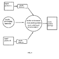
FIG. 1 is a schematic diagram of working principle of the present invention. -
FIG. 2 is a schematic diagram of production of a product of the present invention. -
FIG. 3 is a schematic diagram of cleaning the pipe of the present invention. -
FIG. 4 is a schematic diagram of working principle of the mixing nozzle. -
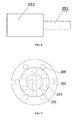
FIGS. 5 and 6 are top view and side view of the mixing nozzle in example 1. -
FIGS. 7 and8 are top view and side view of the mixing nozzle in example 2. -
FIGS. 9 and10 are top view and side view of the mixing nozzle in example 3. -
FIGS. 11 and12 are top view and side view of the mixing nozzle in example 4. - Reference symbols in the figures are as follows:
- The liquid product B is liquid, and it can be solidified immediately to form solid particles when it meets the liquid product A. According, the solid particles can be put into the liquid product an on-line by adding the liquid product B during production of the liquid product A and using the mixed characteristic of the two products so that a sterile solid-liquid mixing product C containing the solid particles is formed in a finished product.
- As shown in
FIG. 1 , the principle of the present invention is that the liquid product A and the liquid product B are simultaneously delivered under sterility condition and then mixed in sterility environment to form the mixing product C containing the solid particles which will be filled into a sterile packaging material to form a sterile particle package. - It should be ensured that during the delivery and filling process the liquid product A reached the first
AP valve bank 11 is sterile, and the liquid product B reached the secondAP valve bank 21 is sterile, and the sterile solid-liquid mixing product C containing the solid particles is formed by mixing the sterile liquid product A with the sterile liquid product B in a sterile state at themixing nozzle 25. Each process of the production of the sterile solid-liquid mixing product C containing the solid particles is sterilized to achieve sterility. The sterilization methods mainly comprise hot air sterilization or hydrogen peroxide sterilization. - As shown in
FIG. 2 , the present invention comprises a filling system and a system for on-line particle adding. The present invention comprises aninjection pipe 31, a first AP valve bank 11 (sterile product valve bank) and a second AP valve bank 21 (sterile product valve bank). The firstAP valve bank 11 is in connection with theinjection pipe 31 through a firstflow control valve 12. The secondAP valve bank 21 is in connection with theinjection pipe 31 through a secondflow control valve 22. The secondflow control valve 22 is in connection with theinjection pipe 31 through a second communicatingpipe 26. - A
flow transducer 23 and adosing valve 24 are disposed on the second communicatingpipe 26, and a mixingnozzle 25 is disposed at the end of the second communicatingpipe 26 and at the junction of the second communicatingpipe 26 and theinjection pipe 31. The mixingnozzle 25 is also in connected with theinjection pipe 31. - The first
AP valve bank 11 is used to add the liquid product A into theinjection pipe 31 while the secondAP valve bank 21 is used to add the liquid product B into theinjection pipe 31, and the liquid product A meets with the liquid product B at the mixingnozzle 25 to form particles in theinjection pipe 31 so that the particles can be filled into the package at themolding unit 33 of the sterile solid-liquid mixing product C. - Without using the
flow transducer 23 and thedosing valve 24, the content ratio of the solid particles in the sterile solid-liquid mixing product C can be controlled precisely by controlling the firstflow control valve 12 and the secondflow control valve 22. - With using the
flow transducer 23 and thedosing valve 24, the content ratio of the solid particles in the sterile solid-liquid mixing product C can be controlled precisely by controlling the firstflow control valve 12, the secondflow control valve 22, theflow transducer 23 and thedosing valve 24. - The
flow transducer 23 is used to monitor the flow of the liquid product B in the second communicatingpipe 26. - As shown in
FIG. 4 , the working principle and function of the mixingnozzle 25 are that the liquid product B can be sprayed out from the through-holes 250 of the mixingnozzle 25 when the product pressure of the liquid product B is greater than that of the liquid product A so that the liquid product B meets the liquid product A and can be solidified immediately to form solid particles. According, the solid particles can be put into the liquid product an on-line by using the mixed characteristic of the two products, thereby a sterile solid-liquid mixing product C containing the solid particles is formed in the finished product. - The present invention is desired to be sterilized to conduct the production in a sterile state. The sterilization methods mainly comprise hot air sterilization or hydrogen peroxide sterilization. The
injection pipe 31 is disposed in thesterile tank 32. - As shown in
FIG. 3 , a method of series cleaning is used for the cleaning of the present invention, which comprises a cleaning pipeline which is in connection with the secondAP valve bank 21, the firstAP valve bank 11 andinjection pipe 31 in turn. When the pipes are cleaning, the cleaning solution travels from theouter cleaning station 42 to the secondAP valve bank 21 throughreversible pipe 43, and travels to the secondAP valve bank 22, the flow transducer 23 (optional component) and the dosing valve 24 (optional component) in turn, then travels to the firstAP valve bank 11 through thereversible pipes flow control valve 12 and theinjection pipe 31 in turn. Theinjection pipe 31 is in connection with theouter cleaning station 42 through the fillingpipe 41. The cleaning circulation is finished after the cleaning solution travels out from theinjection pipe 31 and back to theouter cleaning station 42 through the fillingpipe 41. The cleaning solution is driven by standard cleaning solution provided by theouter cleaning station 42. The mixing nozzle is taken out to be cleaned manually during the cleaning. Accordingly, the system is cleaned effectively and thoroughly after the production. The cleaning pipeline achieves the clean-in-place (CIP) function of the present system with the aid of the existing pipes for production according to the present invention. - The filling
pipe 41 herein has a function that it can be cleaned thoroughly by being inserted into the cleaning circuit during the cleaning, and then taken out after the cleaning is finished to connect to theinjection pipe 31 to form a filling pipeline finally so that the filling liquid level of the solid-liquid mixed product C being controlled precisely can be monitored. - When the cleaning is required for the present invention after the production, a new cleaning pipeline can be formed by changing the connection of the pipes used for the production of the present invention by reversing the first
reversible pipe 43, the secondreversible pipe 44 and the thirdreversible pipe 45 as depicted inFIG. 3 only from bottom (dotted lines) to top (solid line) to connect with the corresponding cleaning pipeline. Specifically, as shown inFIG. 3 , the firstreversible pipe 43, the secondreversible pipe 44 and the thirdreversible pipe 45 are detachably connected to the production pipeline. When the cleaning is required for the present invention after the production, one end of the firstreversible pipe 43, the secondreversible pipe 44 and the thirdreversible pipe 45 is detached and turned over respectively to connect to the corresponding pipe coupling of the cleaning pipeline so that a closed cleaning pipeline is formed. Accordingly, the cleaning according to the present invention can be achieved with the aid of the existing pipes for production according to the present invention without reconnection of independent cleaning pipeline, thereby improving productive efficiency and reducing equipment costs. - All of the steps of the above-mentioned sterile on-line continuous forming and filling of particles are controlled by process control soft wares.
- As shown in
FIG. 2 , the secondAP valve bank 21 is in connection with theinjection pipe 31 through the mixingnozzle 25, and is also in connection with the firstAP valve bank 11 through the mixingnozzle 25. The secondAP valve bank 21 is in connection with the second communicatingpipe 26, and the firstAP valve bank 11 is in connection with a first communicating pipe 13, the second communicatingpipe 26 meeting the first communicating pipe 13 at a junction J, and theinjection pipe 31 bending at a curved part, thereby theinjection pipe 31 comprising horizontal andvertical injection pipes 31. The mixingnozzle 25 is disposed on the second communicatingpipe 26 and near the junction J. - The horizontal injection pipe is required to have a certain length because that if the liquid product B is mixed with the liquid product A in the vertical injection pipe, the solid particles are difficult to formed due to the influence of gravity and the like. However it is disadvantageous for the sterilization of the product if the length of the horizontal injection pipe is too long. Accordingly, the distance of the end of the mixing
nozzle 25 near the junction from the curved part is between 1 m and 3 m. - Preferably, the distance of the end of the mixing
nozzle 25 near the junction from the curved part is between 2 m and 2.5 m. - Preferably, the distance of the end of the mixing
nozzle 25 near the junction from the curved part is between 1.5 m and 2 m. - According to example 1 illustrated by
FIG. 5 , the mixingnozzle 25 possesses a plurality of through-holes 250 which are in connection with the secondAP valve bank 21 and theinjection pipe 31 and further in connection with the secondAP valve bank 21 and the firstAP valve bank 11. The amount of the through-holes 250 in the mixingnozzle 25 ranges from 16 to 24. The through-holes 250 are arranged in an optional equispaced-arrangement manner. - As shown in
FIG. 6 , the shape of mixingnozzle 25 is cylinder-, cone- or circular truncated cone-shaped. The mixingnozzle 25 has a length along the direction of the through-holes ranging from 10 mm to 60 mm. The length of the mixingnozzle 25 is dependent on the shape thereof and the distance of the end thereof near the junction J from the curved part. - According to example 2 illustrated by
FIGS. 7 and8 , the mixingnozzle 25 is configured into two segments which consist of afirst segment 251 and asecond segment 252, each of which having different radial size, and thefirst segment 251 being in connection with thesecond segment 252, thereby thewhole mixing nozzle 25 having a ladder shape. Thefirst segment 251 and thesecond segment 252 are configured to have the through-holes 250 with an amount ranging from 8 to 16. The through-holes 250 are arranged in an optional equispaced- arrangement manner. The length along the direction of the through-holes of thefirst segment 251 and thesecond segment 252 are respectively one selected from the group consisting of 15mm/20mm, 20mm/20mm and 30mm/30mm. - According to example 3 illustrated by
FIGS. 9 and10 , the mixingnozzle 25 is configured into three segments which consist of athird segment 253, afourth segment 254 and afifth segment 255, each of which having different radial size, and the segments from 253 to 255 being connected in turn, thereby thewhole mixing nozzle 25 having a ladder shape. Thethird segment 253, thefourth segment 254 and thefifth segment 255 are configured to have the through-holes 250 with an amount ranging from 16 to 22. The length along the direction of the through-holes of thethird segment 253, thefourth segment 254 and thefifth segment 255 are respectively one selected from the group consisting of 15mm/15mm/20mm, 15mm/20mm/20mm and 20mm/20mm/20mm. The shape of each segment of the mixingnozzle 25 is cylinder- or corrugated pipe-shaped. For example, thethird segment 253 and thefourth segment 254 are configured to be corrugated pipe-shaped. The so-called corrugated pipe-shaped is similar to the shape of gears as shown inFIG. 11 . The through-hole 250 is disposed on each thick gear. - According to example 4 illustrated by
FIGS. 11 and12 , the mixingnozzle 25 is configured into four segments which consist of asixth segment 256, aseventh segment 257, aeighth segment 258 and aninth segment 259, each of which having different radial size, and the segments from 256 to 259 being connected in turn, thereby thewhole mixing nozzle 25 having a ladder shape. The segments from 256 to 259 are configured to have the through-holes 250 with an amount ranging from 16 to 22. The mixingnozzle 25 has a total length ranging from 45 mm to 80 mm. The lengths along the direction of the through-holes of the segments from 256 to 259 respectively are 15mm/15mm/20mm/20mm. The shape of each segment of the mixingnozzle 25 is cylinder- or corrugated pipe-shaped. - The diameters of the through-holes according to the above-mentioned multiple examples are between 1.2 mm to 3.0 mm. The amount of the through-holes in the above-mentioned
mixing nozzle 25 is dependent on the requirement for sterilization of user and for the addition proportion of the solid particle. The mixingnozzle 25 can also be configured into more than four segments, and each segment of the mixing nozzle 25 (from thefirst segment 251 to the ninth segment 252) ranges respectively from 10 mm to 50 mm. The term "multiple" according to the present invention refers to two or more. - In order to ensure that the production is carried out in the sterile state, the sterile filling system is required to be sterilized before carrying out the production. The sterilization steps mainly comprise the steps of drying, pre-sterilization, spraying and drying and so on.
- Firstly, the drying step is carried out. The pipeline of the system is blown for about 6 minutes to remove the residual moisture within the pipeline, thereby drying the pipeline.
- Secondly, the pre-sterilization step is carried out. The pipeline of the system is sterilized at high temperature.
- When the pre-sterilization temperature K is less than a predetermined value, the B valve of the second
AP valve bank 21B is closed, and the sterile air flows through the B valve of the firstAP valve bank 11B, the firstflow control valve 12 and theinjection 31 to thesterile tank 32. - When the pre-sterilization temperature K is greater than a predetermined value in a certain range, the B valve of the first
AP valve bank 11B is closed, and the sterile air flows through the firstreversible pipe 43, the B valve of the second AP valve bank 2 1 B, the secondflow control valve 22, theflow transducer 23, thedosing valve 24, the thirdreversible pipe 45, the mixingnozzle 25 and theinjection 31 to thesterile tank 32. - When the pre-sterilization temperature K reaches the predetermined spray temperature, a few minutes later the B valve of the second
AP valve bank 21B and the B valve of the firstAP valve bank 11B open simultaneously. - Thirdly, the spraying step is carried out. The system is required to be sprayed twice, and the pipeline of the system is required to be sprayed with hydrogen peroxide (H2O2) for sterilization.
- The first spray is carried out. After the start of the first spray, the B valve of the second
AP valve bank 21B close. At the same time the B valve of the firstAP valve bank 11B open. The pipeline for the liquid product A is sterilized by flowing the atomizing H2O2 through the B valve of the firstAP valve bank 11B, the firstflow control valve 12 and theinjection pipe 31 to thesterile tank 32. - The B valve of the second
AP valve bank 21 B and the B valve of the firstAP valve bank 11B close simultaneously within a certain time before the end of the first spray. - The second spray is carried out. After the pre-sterilization temperature K reaches the predetermined spray temperature, a certain time later the second spray is performed.
- The B valve of the second
AP valve bank 21 B open and the B valve of the firstAP valve bank 11B close simultaneously at the beginning of the second spray. The pipeline for the liquid product B is sterilized by flowing the atomizing H2O2 through the firstreversible pipe 43, the B valve of the secondAP valve bank 21B, the secondflow control valve 22, theflow transducer 23, thedosing valve 24, the thirdreversible pipe 45, the mixingnozzle 25 and theinjection pipe 31 to thesterile tank 32. - The B valve of the second
AP valve bank 21 B and the B valve of the firstAP valve bank 11B close simultaneously within a certain time before the end of the second spray. - It is desired that the B valve of the second
AP valve bank 21B open for 5 seconds at the beginning of the first spray and then close again, which can make sure that the residual air within the firstreversible pipe 43, the B valve of the secondAP valve bank 21B, the secondflow control valve 22, theflow transducer 23, thedosing valve 24, the thirdreversible pipe 45, the mixing nozzle and the additional pipe has been sterilized before the second spray. - Fourthly, the drying step is carried out. The hydrogen peroxide (H2O2) within the system is required to be dried after carrying out the two sprays.
- The B valve of the second
AP valve bank 21 B and the B valve of the firstAP valve bank 11B will open and close interchangeably to dry the two pipes. - The butterfly valve BF will open and close based on the open states of the B valve of the second
AP valve bank 21B and the B valve of the firstAP valve bank 11B. - The sterility environment around the system is ensured after performing the steps of drying, pre-sterilization, spraying and drying and so on, thereby preparing for the subsequent production.
- When carrying out the production, the second
AP valve bank 21 open at first, and a certain times later the firstAP valve bank 11 open, and the solid-liquid mixed product C flows through theinjection pipe 31 to themolding unit 33 to form the final sterile packaging product. - The present invention illustrated only with reference to the embodiments is not intended to limit the scope of the present invention. It is easy for those skilled in the art to carry out various different alternation, modification and utilization of equivalent manner without depart from the scope of the claims, which all fall into the scope of the present invention.
| A. |
259. ninth segment |
| B. |
250. through-holes |
| C. solid-liquid |
11B. B valve of the first |
| 11. first AP |
26. second communicating |
| 12. first |
31. |
| 21. second AP |
311. |
| 22. second |
32. |
| 23. |
33. |
| 24. |
41. |
| 25. mixing |
42. |
| 251. |
43. first |
| 252. |
44. second |
| 253. |
45. third |
| 254. |
21B. B valve of the second |
| 255. fifth segment | K. pre-sterilization |
| 256. sixth segment | J. |
| 257. seventh segment | BF. |
| 258. eighth segment |
Claims (33)
- A sterile filling system for on-line particle adding, comprising a filling system, characterized in that it further comprises a system for on-line particle adding.
- The sterile filling system for on-line particle adding according to claim 1, characterized in that the filling system comprises a first AP valve bank (11) and an injection pipe (31), the first AP valve bank (11) and the injection pipe (31) being in connection with each other; and the system for on-line particle adding comprises a second AP valve bank (21), the second AP valve bank (21) being in connection with the injection pipe (31).
- The sterile filling system for on-line particle adding according to claim 2, characterized in that the second AP valve bank (21) is in connection with the injection pipe (31) through a second flow control valve (22).
- The sterile filling system for on-line particle adding according to claim 2, characterized in that the first AP valve bank (11) is in connection with the injection pipe (31) through a first flow control valve (12).
- The sterile filling system for on-line particle adding according to claim 2, characterized in that the first AP valve bank (11) and the second AP valve bank (21) are in connection with the injection pipe (31) through a mixing nozzle (25).
- The sterile filling system for on-line particle adding according to claim 3, characterized in that the second flow control valve (22) is in connection with the injection pipe (31) through a second communicating pipe (26), on which pipe is disposed a flow transducer (23) and a dosing valve (24).
- The sterile filling system for on-line particle adding according to claim 2, characterized in that it further comprises an on-line cleaning system.
- The sterile filling system for on-line particle adding according to claim 7, characterized in that the cleaning system comprises an outer cleaning station (42) and a plurality of reversible pipes (43, 44, 45), the reversible pipes being detachably connected to channels of the filling system and being capable of connecting to the outer cleaning station (42), the filling system, and the system for on-line particle adding in a reversible manner to form series connected cleaning pipeline.
- The sterile filling system for on-line particle adding according to claim 8, characterized in that the injection pipe (31) is in connection with the outer cleaning station (42) through a filling pipe (41).
- The sterile filling system for on-line particle adding according to claim 2, characterized in that the second AP valve bank (21) is in connection with the injection pipe (31) through the mixing nozzle (25), and is in connection with the first AP valve bank (11) through the mixing nozzle (25).
- The sterile filling system for on-line particle adding according to claim 10, characterized in that the second AP valve bank (21) is in connection with the second communicating pipe (26), and the first AP valve bank (11) is in connection with a first communicating pipe (13), the second communicating pipe (26) meeting the first communicating pipe (13) at a junction (J), and the injection pipe (31) bending at a curved part.
- The sterile filling system for on-line particle adding according to claim 11, characterized in that the mixing nozzle (25) is disposed on the second communicating pipe (26) and near the junction (J), and a distance of the end of the mixing nozzle (25) near the junction from the curved part is between 1 m and 3 m.
- The sterile filling system for on-line particle adding according to claim 12, characterized in that the distance of the end of the mixing nozzle (25) near the junction from the curved part is between 2 m and 2.5 m.
- The sterile filling system for on-line particle adding according to claim 12, characterized in that the distance of the end of the mixing nozzle (25) near the junction from the curved part is between 1.5 m and 2 m.
- The sterile filling system for on-line particle adding according to claim 12, characterized in that the mixing nozzle (25) possesses a plurality of through-holes (250) which are in connection with the second AP valve bank (21) and the injection pipe (31) and further in connection with the second AP valve bank (21) and the first AP valve bank (11).
- The sterile filling system for on-line particle adding according to claim 15, characterized in that the shape of mixing nozzle (25) is cylinder-, cone- or circular truncated cone-shaped.
- The sterile filling system for on-line particle adding according to claim 16, characterized in that the mixing nozzle (25) has a length along the direction of the through-holes ranging from 10 mm to 60 mm.
- The sterile filling system for on-line particle adding according to claim 17, characterized in that the amount of the through-holes (250) in the mixing nozzle (25) ranges from 16 to 24.
- The sterile filling system for on-line particle adding according to claim 17, characterized in that the mixing nozzle (25) is configured into two segments which consist of a first segment (251) and a second segment (252), each of which having different radial size, and the first segment (251) being in connection with the second segment (252), thereby the whole mixing nozzle (25) having a ladder shape.
- The sterile filling system for on-line particle adding according to claim 19, characterized in that the first segment (251) and the second segment (252) are configured to have the through-holes (250) with an amount ranging from 8 to 16.
- The sterile filling system for on-line particle adding according to claim 20, characterized in that the first segment (251) and the second segment (252) have a length along the direction of the through-holes respectively ranging from 10 mm to 50 mm.
- The sterile filling system for on-line particle adding according to claim 21, characterized in that the length along the direction of the through-holes of the first segment (251) and the second segment (252) are respectively one selected from the group consisting of 15mm/20mm, 20mm/20mm and 30mm/30mm.
- The sterile filling system for on-line particle adding according to claim 15, characterized in that the mixing nozzle (25) is configured into three segments which consist of a third segment (253), a fourth segment (254) and a fifth segment (255), each of which having different radial size, and the segments from (253) to (255) being connected in turn, thereby the whole mixing nozzle (25) having a ladder shape.
- The sterile filling system for on-line particle adding according to claim 23, characterized in that the third segment (253), the fourth segment (254) and the fifth segment (255) are configured to have the through-holes (250) with an amount ranging from 16 to 22.
- The sterile filling system for on-line particle adding according to claim 24, characterized in that the third segment (253), the fourth segment (254) and the fifth segment (255) have a length along the direction of the through-holes respectively ranging from 10 mm to 50 mm.
- The sterile filling system for on-line particle adding according to claim 25, characterized in that the length along the direction of the through-holes of the third segment (253), the fourth segment (254) and the fifth segment (255) are respectively one selected from the group consisting of 15mm/15mm/20mm, 15mm/20mm/20mm and 20mm/20mm/20mm.
- The sterile filling system for on-line particle adding according to claim 15, characterized in that the mixing nozzle (25) is configured into four segments which consist of a sixth segment (256), a seventh segment (257), a eighth segment (258) and a ninth segment (259), each of which having different radial size, and the segments from (256) to (259) being connected in turn, thereby the whole mixing nozzle (25) having a ladder shape.
- The sterile filling system for on-line particle adding according to claim 27, characterized in that the segments from (256) to (259) are configured to have the through-holes (250) with an amount ranging from 16 to 22.
- The sterile filling system for on-line particle adding according to claim 28, characterized in that the mixing nozzle (25) has a total length ranging from 45 mm to 80 mm.
- The sterile filling system for on-line particle adding according to claim 29, characterized in that the segments from (256) to (259) have a length along the direction of the through-holes respectively ranging from 10 mm to 50 mm.
- The sterile filling system for on-line particle adding according to claim 30, characterized in that the length along the direction of the through-holes of the segments from (256) to (259) respectively are 15mm/15mm/20mm/20mm.
- The sterile filling system for on-line particle adding according to any one of claims 19 to 31, characterized in that the shape of each segment of the mixing nozzle (25) is cylinder- or corrugated pipe-shaped.
- The sterile filling system for on-line particle adding according to any one of claims 15 to 32, characterized in that the through-holes (250) have a diameter between 1.2 mm and 3.0 mm.
Applications Claiming Priority (2)
| Application Number | Priority Date | Filing Date | Title |
|---|---|---|---|
| CN2010201365556U CN201647160U (en) | 2010-02-23 | 2010-02-23 | Aseptic perfusion system with in-line addition of particles |
| PCT/CN2011/071206 WO2011103802A1 (en) | 2010-02-23 | 2011-02-23 | Aseptic filling system with online adding of particles |
Publications (2)
| Publication Number | Publication Date |
|---|---|
| EP2540627A1 true EP2540627A1 (en) | 2013-01-02 |
| EP2540627A4 EP2540627A4 (en) | 2016-01-20 |
Family
ID=43112388
Family Applications (1)
| Application Number | Title | Priority Date | Filing Date |
|---|---|---|---|
| EP11746844.7A Withdrawn EP2540627A4 (en) | 2010-02-23 | 2011-02-23 | ASEPTIC FILLING SYSTEM WITH ONLINE ADDING OF PARTICLES |
Country Status (8)
| Country | Link |
|---|---|
| US (1) | US9346025B2 (en) |
| EP (1) | EP2540627A4 (en) |
| JP (1) | JP5683611B2 (en) |
| CN (2) | CN201647160U (en) |
| BR (1) | BR112012020997A2 (en) |
| MX (1) | MX336704B (en) |
| RU (1) | RU2556391C2 (en) |
| WO (1) | WO2011103802A1 (en) |
Cited By (2)
| Publication number | Priority date | Publication date | Assignee | Title |
|---|---|---|---|---|
| WO2016001144A1 (en) * | 2014-06-30 | 2016-01-07 | Tetra Laval Holdings & Finance S.A. | A method for efficiently emptying a system with liquid product |
| WO2016001146A1 (en) * | 2014-06-30 | 2016-01-07 | Tetra Laval Holdings & Finance S.A. | A method for efficiently filling a system with liquid product |
Families Citing this family (6)
| Publication number | Priority date | Publication date | Assignee | Title |
|---|---|---|---|---|
| CN201647160U (en) * | 2010-02-23 | 2010-11-24 | 利乐拉瓦尔集团及财务有限公司 | Aseptic perfusion system with in-line addition of particles |
| CN105129118B (en) * | 2015-06-12 | 2017-11-17 | 青海青海湖乳业有限责任公司 | A kind of device and method thereof for being used to fill edible shot-like particle into acidified milk |
| CN106085840B (en) * | 2016-06-21 | 2018-04-10 | 上海艾魁英生物科技有限公司 | The pipe-line transportation system of KLP-602 sodium alginate micro ball production line and purging system on the spot |
| CN107258903A (en) * | 2017-06-19 | 2017-10-20 | 吴再盛 | After " reduction " high-temperature process in milk vitamin A Processes and apparatus |
| CN115121150A (en) * | 2021-03-23 | 2022-09-30 | 内蒙古伊利实业集团股份有限公司 | Aseptic whipping inflation system |
| CN119348953B (en) * | 2023-07-24 | 2025-10-28 | 内蒙古蒙牛乳业(集团)股份有限公司 | Filling production system |
Family Cites Families (32)
| Publication number | Priority date | Publication date | Assignee | Title |
|---|---|---|---|---|
| NL154819B (en) * | 1967-05-10 | 1977-10-17 | Shell Int Research | DEVICE FOR APPLYING A LOW VISCOSITY LAYER OF LIQUID BETWEEN A FLOW OF HIGH VISCOSITY LIQUID AND THE WALL OF A PIPELINE. |
| DE2230185A1 (en) | 1972-06-21 | 1974-01-24 | Davy Ashmore Ag | Additive mixt - with shroud and tubes in mainstream for additive to be collected from counter stream |
| US4468127A (en) * | 1980-09-02 | 1984-08-28 | Vito Agosta | Process for metering and mixing liquids in arbitrary mass proportions |
| SE437136B (en) | 1984-03-08 | 1985-02-11 | Tetra Pak Int | SET AND DEVICE FOR MANUFACTURING AND FILLING OF PACKAGING CONTAINERS |
| US4979091A (en) * | 1986-10-27 | 1990-12-18 | Phillips Petroleum Company | Control of a blending system |
| US5179970A (en) * | 1987-10-23 | 1993-01-19 | The Coca-Cola Company | Beverage dispensing valve |
| JPH0780508B2 (en) | 1988-12-15 | 1995-08-30 | 凸版印刷株式会社 | Filling device for liquid containing solid matter |
| JPH041899U (en) | 1990-04-18 | 1992-01-09 | ||
| JPH0441899U (en) | 1990-08-02 | 1992-04-09 | ||
| JP3007757B2 (en) | 1992-07-27 | 2000-02-07 | 雪印乳業株式会社 | Method and apparatus for filling solid-liquid mixture |
| JP2585172B2 (en) | 1992-11-06 | 1997-02-26 | 日清製油株式会社 | New jelly-like beverage |
| FR2708563B1 (en) | 1993-08-02 | 1995-10-27 | Erca | Unit and method for dosing and distribution of liquid and / or pasty products. |
| SE508137C2 (en) | 1996-12-19 | 1998-08-31 | Tetra Laval Holdings & Finance | Method and apparatus for continuous mixing of two streams |
| JP3779070B2 (en) | 1998-08-21 | 2006-05-24 | 森永乳業株式会社 | Method for producing multilayer gelled food |
| SE518088C2 (en) | 2000-10-30 | 2002-08-27 | Tetra Laval Holdings & Finance | Method and apparatus for mixing two phases of a food product |
| RU2000132898A (en) | 2000-12-28 | 2003-01-10 | Закрытое акционерное общество "Новгородский машиностроительный завод" | METHOD FOR ASEPTIC CONVEYOR FILLING OF LIQUID FOOD PRODUCTS IN A PIECE OF FINISHED PACKAGING AND DEVICE FOR ITS IMPLEMENTATION |
| US6889603B2 (en) * | 2002-12-24 | 2005-05-10 | Nestec S.A. | Clean-in-place automated food or beverage dispenser |
| JP4512913B2 (en) * | 2003-04-07 | 2010-07-28 | 旭有機材工業株式会社 | Fluid mixing device |
| US20060209624A1 (en) | 2003-08-21 | 2006-09-21 | Hans Hoogland | Apparatus and method for mixing components |
| JP4015134B2 (en) * | 2004-04-22 | 2007-11-28 | 株式会社イズミフードマシナリ | Method for reducing dissolved oxygen concentration in beverages |
| US8046976B2 (en) | 2006-07-25 | 2011-11-01 | The Coca-Cola Company | Devices and methods for packaging beverages |
| DE102006045987A1 (en) * | 2006-09-27 | 2008-04-03 | Khs Ag | Method for filling containers with a liquid product and filling system |
| DE102006047969A1 (en) * | 2006-10-11 | 2008-04-17 | Niro-Plan Ag | Apparatus for preparing and dispensing beverages with a cleaning device |
| US8371291B2 (en) * | 2006-10-19 | 2013-02-12 | G. Greg Haroutunian | Flow modification device |
| JP2008148633A (en) | 2006-12-18 | 2008-07-03 | Morinaga Milk Ind Co Ltd | Lactic acid bacteria fermented food containing tofu puree |
| US8678239B2 (en) * | 2007-07-13 | 2014-03-25 | The Coca-Cola Company | Clean in place system for beverage dispensers |
| CN101543246B (en) * | 2008-03-25 | 2011-09-07 | 内蒙古伊利实业集团股份有限公司 | Method for producing liquid milk product containing fruit-vegetable granules |
| US20100031825A1 (en) * | 2008-08-05 | 2010-02-11 | Kemp David M | Blending System |
| DE102008038638A1 (en) * | 2008-08-12 | 2010-02-25 | Khs Ag | A method for filling a filling material consisting of at least one first and one second component |
| CN101427724B (en) | 2008-11-28 | 2012-12-12 | 内蒙古伊利实业集团股份有限公司 | Liquid milk product containing gellan gum particle and producing method thereof |
| JP2010274971A (en) | 2009-05-29 | 2010-12-09 | Nihon Tetra Pak Kk | Packaging and filling equipment |
| CN201647160U (en) | 2010-02-23 | 2010-11-24 | 利乐拉瓦尔集团及财务有限公司 | Aseptic perfusion system with in-line addition of particles |
-
2010
- 2010-02-23 CN CN2010201365556U patent/CN201647160U/en not_active Expired - Lifetime
-
2011
- 2011-02-23 JP JP2012554207A patent/JP5683611B2/en not_active Expired - Fee Related
- 2011-02-23 EP EP11746844.7A patent/EP2540627A4/en not_active Withdrawn
- 2011-02-23 MX MX2012009704A patent/MX336704B/en unknown
- 2011-02-23 WO PCT/CN2011/071206 patent/WO2011103802A1/en not_active Ceased
- 2011-02-23 CN CN201180009558.0A patent/CN102892677B/en not_active Expired - Fee Related
- 2011-02-23 BR BR112012020997A patent/BR112012020997A2/en not_active Application Discontinuation
- 2011-02-23 RU RU2012140478/13A patent/RU2556391C2/en not_active IP Right Cessation
- 2011-02-23 US US13/580,854 patent/US9346025B2/en not_active Expired - Fee Related
Cited By (4)
| Publication number | Priority date | Publication date | Assignee | Title |
|---|---|---|---|---|
| WO2016001144A1 (en) * | 2014-06-30 | 2016-01-07 | Tetra Laval Holdings & Finance S.A. | A method for efficiently emptying a system with liquid product |
| WO2016001146A1 (en) * | 2014-06-30 | 2016-01-07 | Tetra Laval Holdings & Finance S.A. | A method for efficiently filling a system with liquid product |
| CN106458553A (en) * | 2014-06-30 | 2017-02-22 | 利乐拉瓦尔集团及财务有限公司 | A method for efficiently filling a system with a liquid product |
| CN106660650A (en) * | 2014-06-30 | 2017-05-10 | 利乐拉瓦尔集团及财务有限公司 | A method for efficiently emptying a system with a liquid product |
Also Published As
| Publication number | Publication date |
|---|---|
| BR112012020997A2 (en) | 2016-05-03 |
| WO2011103802A1 (en) | 2011-09-01 |
| CN102892677A (en) | 2013-01-23 |
| RU2012140478A (en) | 2014-03-27 |
| US9346025B2 (en) | 2016-05-24 |
| US20120312405A1 (en) | 2012-12-13 |
| JP2013520373A (en) | 2013-06-06 |
| CN201647160U (en) | 2010-11-24 |
| RU2556391C2 (en) | 2015-07-10 |
| CN102892677B (en) | 2014-07-30 |
| MX336704B (en) | 2016-01-28 |
| JP5683611B2 (en) | 2015-03-11 |
| MX2012009704A (en) | 2012-10-01 |
| EP2540627A4 (en) | 2016-01-20 |
Similar Documents
| Publication | Publication Date | Title |
|---|---|---|
| US9346025B2 (en) | Sterile filling system for on-line particle adding | |
| JP6544409B2 (en) | Beverage filling device | |
| US11103607B2 (en) | Method and apparatus for sterilizing filling nozzle | |
| CN108669404B (en) | A kind of configuration sterilization equipment and configuration method of particle-containing liquid beverage | |
| CN105815536A (en) | Living bacterium-containing fermented soft ice cream or soft popsicle paste and preparation method thereof | |
| CN107027888A (en) | A kind of normal-temperature yoghourt for adding fruit particle and preparation method thereof | |
| AU2013225818B2 (en) | Method of manufacturing protein beverages and denaturizing loop apparatus and system | |
| CN215292880U (en) | Aseptic storage conveying system suitable for different viscosity materials | |
| CN205132295U (en) | Packagine machine material feeding unit that passes through | |
| CN207389720U (en) | A kind of rice wine crock high-temperature sterilization mechanism | |
| CN106615113A (en) | Room-temperature yogurt with added plant seed particles and preparation method of room-temperature yogurt | |
| CN224222269U (en) | Cup cleaning device | |
| CN106798007A (en) | A kind of three-sectional low temperature ultra-high pressure processing method suitable for fresh donkey milk | |
| CN218754943U (en) | Liquid injection pipe device and filling machine device based on mixed liquid beverage | |
| JP5128628B2 (en) | Method for producing food and drink containing jelly | |
| JP5128567B2 (en) | Method for producing food and drink containing jelly | |
| CN121101130A (en) | A method for aseptic docking of jam and its application | |
| CN207054765U (en) | A kind of fruits and vegetables inspissated juice adding set | |
| CN105129118B (en) | A kind of device and method thereof for being used to fill edible shot-like particle into acidified milk | |
| CN206828499U (en) | Fruit vinegar produces homogeneous system | |
| CN107258903A (en) | After " reduction " high-temperature process in milk vitamin A Processes and apparatus | |
| CN204368463U (en) | A kind of lactic acid bacteria beverage filling production lines | |
| WO2009143521A3 (en) | Dairy cream products and methods | |
| Milks | Manufacture of Yoghurt and Other | |
| HK1125265A1 (en) | Multilayer food product and method for preparing same |
Legal Events
| Date | Code | Title | Description |
|---|---|---|---|
| PUAI | Public reference made under article 153(3) epc to a published international application that has entered the european phase |
Free format text: ORIGINAL CODE: 0009012 |
|
| 17P | Request for examination filed |
Effective date: 20120824 |
|
| AK | Designated contracting states |
Kind code of ref document: A1 Designated state(s): AL AT BE BG CH CY CZ DE DK EE ES FI FR GB GR HR HU IE IS IT LI LT LU LV MC MK MT NL NO PL PT RO RS SE SI SK SM TR |
|
| DAX | Request for extension of the european patent (deleted) | ||
| RA4 | Supplementary search report drawn up and despatched (corrected) |
Effective date: 20151222 |
|
| RIC1 | Information provided on ipc code assigned before grant |
Ipc: B65B 55/18 20060101ALI20151216BHEP Ipc: B01F 3/08 20060101ALI20151216BHEP Ipc: B65B 9/12 20060101ALI20151216BHEP Ipc: B01F 15/00 20060101ALI20151216BHEP Ipc: B01F 5/20 20060101AFI20151216BHEP |
|
| STAA | Information on the status of an ep patent application or granted ep patent |
Free format text: STATUS: EXAMINATION IS IN PROGRESS |
|
| 17Q | First examination report despatched |
Effective date: 20190814 |
|
| GRAP | Despatch of communication of intention to grant a patent |
Free format text: ORIGINAL CODE: EPIDOSNIGR1 |
|
| STAA | Information on the status of an ep patent application or granted ep patent |
Free format text: STATUS: GRANT OF PATENT IS INTENDED |
|
| INTG | Intention to grant announced |
Effective date: 20210812 |
|
| GRAS | Grant fee paid |
Free format text: ORIGINAL CODE: EPIDOSNIGR3 |
|
| STAA | Information on the status of an ep patent application or granted ep patent |
Free format text: STATUS: THE APPLICATION IS DEEMED TO BE WITHDRAWN |
|
| 18D | Application deemed to be withdrawn |
Effective date: 20211223 |