EP2540376A1 - Method for deacidifying a gas with a plurality of steps of placing in co-current contact with an absorbent solution - Google Patents
Method for deacidifying a gas with a plurality of steps of placing in co-current contact with an absorbent solution Download PDFInfo
- Publication number
- EP2540376A1 EP2540376A1 EP12290193A EP12290193A EP2540376A1 EP 2540376 A1 EP2540376 A1 EP 2540376A1 EP 12290193 A EP12290193 A EP 12290193A EP 12290193 A EP12290193 A EP 12290193A EP 2540376 A1 EP2540376 A1 EP 2540376A1
- Authority
- EP
- European Patent Office
- Prior art keywords
- gas
- absorbent solution
- liquid
- contactor
- acidic compounds
- Prior art date
- Legal status (The legal status is an assumption and is not a legal conclusion. Google has not performed a legal analysis and makes no representation as to the accuracy of the status listed.)
- Withdrawn
Links
Images


Classifications
-
- B—PERFORMING OPERATIONS; TRANSPORTING
- B01—PHYSICAL OR CHEMICAL PROCESSES OR APPARATUS IN GENERAL
- B01D—SEPARATION
- B01D53/00—Separation of gases or vapours; Recovering vapours of volatile solvents from gases; Chemical or biological purification of waste gases, e.g. engine exhaust gases, smoke, fumes, flue gases, aerosols
- B01D53/14—Separation of gases or vapours; Recovering vapours of volatile solvents from gases; Chemical or biological purification of waste gases, e.g. engine exhaust gases, smoke, fumes, flue gases, aerosols by absorption
- B01D53/1406—Multiple stage absorption
-
- B—PERFORMING OPERATIONS; TRANSPORTING
- B01—PHYSICAL OR CHEMICAL PROCESSES OR APPARATUS IN GENERAL
- B01D—SEPARATION
- B01D53/00—Separation of gases or vapours; Recovering vapours of volatile solvents from gases; Chemical or biological purification of waste gases, e.g. engine exhaust gases, smoke, fumes, flue gases, aerosols
- B01D53/14—Separation of gases or vapours; Recovering vapours of volatile solvents from gases; Chemical or biological purification of waste gases, e.g. engine exhaust gases, smoke, fumes, flue gases, aerosols by absorption
- B01D53/1456—Removing acid components
- B01D53/1462—Removing mixtures of hydrogen sulfide and carbon dioxide
-
- C—CHEMISTRY; METALLURGY
- C10—PETROLEUM, GAS OR COKE INDUSTRIES; TECHNICAL GASES CONTAINING CARBON MONOXIDE; FUELS; LUBRICANTS; PEAT
- C10L—FUELS NOT OTHERWISE PROVIDED FOR; NATURAL GAS; SYNTHETIC NATURAL GAS OBTAINED BY PROCESSES NOT COVERED BY SUBCLASSES C10G, C10K; LIQUEFIED PETROLEUM GAS; ADDING MATERIALS TO FUELS OR FIRES TO REDUCE SMOKE OR UNDESIRABLE DEPOSITS OR TO FACILITATE SOOT REMOVAL; FIRELIGHTERS
- C10L3/00—Gaseous fuels; Natural gas; Synthetic natural gas obtained by processes not covered by subclass C10G, C10K; Liquefied petroleum gas
- C10L3/06—Natural gas; Synthetic natural gas obtained by processes not covered by C10G, C10K3/02 or C10K3/04
- C10L3/10—Working-up natural gas or synthetic natural gas
- C10L3/101—Removal of contaminants
- C10L3/102—Removal of contaminants of acid contaminants
- C10L3/103—Sulfur containing contaminants
-
- C—CHEMISTRY; METALLURGY
- C10—PETROLEUM, GAS OR COKE INDUSTRIES; TECHNICAL GASES CONTAINING CARBON MONOXIDE; FUELS; LUBRICANTS; PEAT
- C10L—FUELS NOT OTHERWISE PROVIDED FOR; NATURAL GAS; SYNTHETIC NATURAL GAS OBTAINED BY PROCESSES NOT COVERED BY SUBCLASSES C10G, C10K; LIQUEFIED PETROLEUM GAS; ADDING MATERIALS TO FUELS OR FIRES TO REDUCE SMOKE OR UNDESIRABLE DEPOSITS OR TO FACILITATE SOOT REMOVAL; FIRELIGHTERS
- C10L3/00—Gaseous fuels; Natural gas; Synthetic natural gas obtained by processes not covered by subclass C10G, C10K; Liquefied petroleum gas
- C10L3/06—Natural gas; Synthetic natural gas obtained by processes not covered by C10G, C10K3/02 or C10K3/04
- C10L3/10—Working-up natural gas or synthetic natural gas
- C10L3/101—Removal of contaminants
- C10L3/102—Removal of contaminants of acid contaminants
- C10L3/104—Carbon dioxide
-
- B—PERFORMING OPERATIONS; TRANSPORTING
- B01—PHYSICAL OR CHEMICAL PROCESSES OR APPARATUS IN GENERAL
- B01D—SEPARATION
- B01D2252/00—Absorbents, i.e. solvents and liquid materials for gas absorption
- B01D2252/20—Organic absorbents
- B01D2252/202—Alcohols or their derivatives
- B01D2252/2021—Methanol
-
- B—PERFORMING OPERATIONS; TRANSPORTING
- B01—PHYSICAL OR CHEMICAL PROCESSES OR APPARATUS IN GENERAL
- B01D—SEPARATION
- B01D2252/00—Absorbents, i.e. solvents and liquid materials for gas absorption
- B01D2252/20—Organic absorbents
- B01D2252/202—Alcohols or their derivatives
- B01D2252/2023—Glycols, diols or their derivatives
- B01D2252/2025—Ethers or esters of alkylene glycols, e.g. ethylene or propylene carbonate
-
- B—PERFORMING OPERATIONS; TRANSPORTING
- B01—PHYSICAL OR CHEMICAL PROCESSES OR APPARATUS IN GENERAL
- B01D—SEPARATION
- B01D2252/00—Absorbents, i.e. solvents and liquid materials for gas absorption
- B01D2252/20—Organic absorbents
- B01D2252/202—Alcohols or their derivatives
- B01D2252/2023—Glycols, diols or their derivatives
- B01D2252/2026—Polyethylene glycol, ethers or esters thereof, e.g. Selexol
-
- B—PERFORMING OPERATIONS; TRANSPORTING
- B01—PHYSICAL OR CHEMICAL PROCESSES OR APPARATUS IN GENERAL
- B01D—SEPARATION
- B01D2252/00—Absorbents, i.e. solvents and liquid materials for gas absorption
- B01D2252/20—Organic absorbents
- B01D2252/204—Amines
- B01D2252/2041—Diamines
-
- B—PERFORMING OPERATIONS; TRANSPORTING
- B01—PHYSICAL OR CHEMICAL PROCESSES OR APPARATUS IN GENERAL
- B01D—SEPARATION
- B01D2252/00—Absorbents, i.e. solvents and liquid materials for gas absorption
- B01D2252/20—Organic absorbents
- B01D2252/204—Amines
- B01D2252/20415—Tri- or polyamines
-
- B—PERFORMING OPERATIONS; TRANSPORTING
- B01—PHYSICAL OR CHEMICAL PROCESSES OR APPARATUS IN GENERAL
- B01D—SEPARATION
- B01D2252/00—Absorbents, i.e. solvents and liquid materials for gas absorption
- B01D2252/20—Organic absorbents
- B01D2252/204—Amines
- B01D2252/20436—Cyclic amines
- B01D2252/20447—Cyclic amines containing a piperazine-ring
-
- B—PERFORMING OPERATIONS; TRANSPORTING
- B01—PHYSICAL OR CHEMICAL PROCESSES OR APPARATUS IN GENERAL
- B01D—SEPARATION
- B01D2252/00—Absorbents, i.e. solvents and liquid materials for gas absorption
- B01D2252/20—Organic absorbents
- B01D2252/204—Amines
- B01D2252/20436—Cyclic amines
- B01D2252/20452—Cyclic amines containing a morpholine-ring
-
- B—PERFORMING OPERATIONS; TRANSPORTING
- B01—PHYSICAL OR CHEMICAL PROCESSES OR APPARATUS IN GENERAL
- B01D—SEPARATION
- B01D2252/00—Absorbents, i.e. solvents and liquid materials for gas absorption
- B01D2252/20—Organic absorbents
- B01D2252/204—Amines
- B01D2252/20436—Cyclic amines
- B01D2252/20468—Cyclic amines containing a pyrrolidone-ring
-
- B—PERFORMING OPERATIONS; TRANSPORTING
- B01—PHYSICAL OR CHEMICAL PROCESSES OR APPARATUS IN GENERAL
- B01D—SEPARATION
- B01D2252/00—Absorbents, i.e. solvents and liquid materials for gas absorption
- B01D2252/20—Organic absorbents
- B01D2252/204—Amines
- B01D2252/20478—Alkanolamines
- B01D2252/20484—Alkanolamines with one hydroxyl group
-
- B—PERFORMING OPERATIONS; TRANSPORTING
- B01—PHYSICAL OR CHEMICAL PROCESSES OR APPARATUS IN GENERAL
- B01D—SEPARATION
- B01D2252/00—Absorbents, i.e. solvents and liquid materials for gas absorption
- B01D2252/20—Organic absorbents
- B01D2252/204—Amines
- B01D2252/20478—Alkanolamines
- B01D2252/20489—Alkanolamines with two or more hydroxyl groups
-
- B—PERFORMING OPERATIONS; TRANSPORTING
- B01—PHYSICAL OR CHEMICAL PROCESSES OR APPARATUS IN GENERAL
- B01D—SEPARATION
- B01D2257/00—Components to be removed
- B01D2257/30—Sulfur compounds
- B01D2257/304—Hydrogen sulfide
-
- B—PERFORMING OPERATIONS; TRANSPORTING
- B01—PHYSICAL OR CHEMICAL PROCESSES OR APPARATUS IN GENERAL
- B01D—SEPARATION
- B01D2257/00—Components to be removed
- B01D2257/30—Sulfur compounds
- B01D2257/306—Organic sulfur compounds, e.g. mercaptans
-
- B—PERFORMING OPERATIONS; TRANSPORTING
- B01—PHYSICAL OR CHEMICAL PROCESSES OR APPARATUS IN GENERAL
- B01D—SEPARATION
- B01D2257/00—Components to be removed
- B01D2257/30—Sulfur compounds
- B01D2257/308—Carbonoxysulfide COS
-
- B—PERFORMING OPERATIONS; TRANSPORTING
- B01—PHYSICAL OR CHEMICAL PROCESSES OR APPARATUS IN GENERAL
- B01D—SEPARATION
- B01D2257/00—Components to be removed
- B01D2257/50—Carbon oxides
- B01D2257/504—Carbon dioxide
-
- B—PERFORMING OPERATIONS; TRANSPORTING
- B01—PHYSICAL OR CHEMICAL PROCESSES OR APPARATUS IN GENERAL
- B01D—SEPARATION
- B01D2258/00—Sources of waste gases
- B01D2258/02—Other waste gases
- B01D2258/0233—Other waste gases from cement factories
-
- B—PERFORMING OPERATIONS; TRANSPORTING
- B01—PHYSICAL OR CHEMICAL PROCESSES OR APPARATUS IN GENERAL
- B01D—SEPARATION
- B01D2258/00—Sources of waste gases
- B01D2258/02—Other waste gases
- B01D2258/025—Other waste gases from metallurgy plants
-
- B—PERFORMING OPERATIONS; TRANSPORTING
- B01—PHYSICAL OR CHEMICAL PROCESSES OR APPARATUS IN GENERAL
- B01D—SEPARATION
- B01D2258/00—Sources of waste gases
- B01D2258/05—Biogas
-
- B—PERFORMING OPERATIONS; TRANSPORTING
- B01—PHYSICAL OR CHEMICAL PROCESSES OR APPARATUS IN GENERAL
- B01D—SEPARATION
- B01D53/00—Separation of gases or vapours; Recovering vapours of volatile solvents from gases; Chemical or biological purification of waste gases, e.g. engine exhaust gases, smoke, fumes, flue gases, aerosols
- B01D53/14—Separation of gases or vapours; Recovering vapours of volatile solvents from gases; Chemical or biological purification of waste gases, e.g. engine exhaust gases, smoke, fumes, flue gases, aerosols by absorption
- B01D53/18—Absorbing units; Liquid distributors therefor
- B01D53/185—Liquid distributors
-
- Y—GENERAL TAGGING OF NEW TECHNOLOGICAL DEVELOPMENTS; GENERAL TAGGING OF CROSS-SECTIONAL TECHNOLOGIES SPANNING OVER SEVERAL SECTIONS OF THE IPC; TECHNICAL SUBJECTS COVERED BY FORMER USPC CROSS-REFERENCE ART COLLECTIONS [XRACs] AND DIGESTS
- Y02—TECHNOLOGIES OR APPLICATIONS FOR MITIGATION OR ADAPTATION AGAINST CLIMATE CHANGE
- Y02E—REDUCTION OF GREENHOUSE GAS [GHG] EMISSIONS, RELATED TO ENERGY GENERATION, TRANSMISSION OR DISTRIBUTION
- Y02E50/00—Technologies for the production of fuel of non-fossil origin
- Y02E50/30—Fuel from waste, e.g. synthetic alcohol or diesel
Definitions
- the present invention relates to the field of deacidification processes of a gas with an absorbent solution.
- the invention relates to contacting the gas with the absorbent solution.
- contactors In gas treatment processes by contacting the gas with a liquid, distillation, reactive distillation, gas treatment or washing processes, mass and heat transfers between a gas phase and a liquid phase, are realized by means of technologies, called contactors, which favor these transfers.
- contactors There are three main types of contactors, bulk packings, structured packings and column trays.
- the contact between the two gas and liquid phases is generally carried out in a column operated against the current, that is to say where the gas follows a globally vertical ascending movement and the liquid follows a globally vertical downward movement. This embodiment is imposed because of the desire to bring into contact the increasingly refined gas phase with a solution of less and less charged liquid and thus not to be limited by thermodynamic equilibrium stresses.
- gas treatment processes which operate in co-downflow mode, such as, for example, sodium washing units or the RedOx gas purification process described in the document. US 4,741,888 ) for performing a finishing step on gases low in acidic compounds.
- the treatment is carried out in a single step, generally with a liquid flow injected in a very large excess with respect to the gas flow rate to be treated.
- the present invention proposes an implementation of staged contacting in co-current mode in a succession of contact zones which can be vertical or horizontal with a flow of the gas and liquid phases in counter-current mode between the contact zones. It is therefore a question of cutting the process into several stages, which on the basic scale are co-current contact, and at the process scale put the gas and liquid flows in countercurrent contact.
- the gas and the liquid can travel the co-current contactors in a downward vertical direction.
- the gas and the liquid can travel the co-current contactors in a horizontal direction.
- the contactors may comprise a lining which develops a geometric area greater than 200 m 2 / m 3 and preferably greater than 400 m 2 / m 3 .
- the gas can be circulated in the contactors at a speed greater than 1 m / s, preferably greater than 2 m / s or even 4 m / s.
- a portion of at least one of the two streams chosen from the gas and the liquid absorbing solution originating from one of the contactors may be taken, and then said portion may be introduced at the inlet of said contactor.
- a portion of a mixture composed of the gas and the absorbent solution from the outlet of one of the contactors can be taken, and then said portion can be introduced at the inlet of said contactor.
- step a) Before performing step a), said acid-enriched liquid absorbent solution produced in step b) can be cooled.
- the absorbent solution loaded with acidic compounds produced in step a) can be regenerated so as to release acidic compounds and produce said absorbent solution used in step b) or said absorbent liquid used in step c. ).
- the absorbent solution may be composed of an aqueous solution comprising amines.
- the feed gas may be chosen from one of the following gases: a combustion smoke, a natural gas, a gas obtained at the bottom of the Claus process, a synthesis gas, a gas resulting from the fermentation of biomass, an effluent resulting from a cement plant and a gas from a steel plant.
- the implementation of the process according to the invention is possible because, on the one hand, of the low thermodynamic limitation of gas washing processes by amine-type absorbent solutions and, on the other hand, because in these processes and, unlike the distillation cases referred to, the flow rates of gas and liquid can be controlled independently (the gas flow rate is set by the process, a minimum flow rate of liquid corresponds to it, but this can be significantly modified if the operator wishes).
- the implementation in co-current mode makes it possible to obtain a flow inducing transfer coefficients mass significantly higher than those obtained with trays or packings operated against the current.
- co-current circulation at the scale of a column allows, on the one hand, to use gas and liquid distribution systems inducing a very good mixture of phases without energy cost on the gas phase and, on the other hand, to use very effective gas-liquid contact technologies such as static mixers or high surface area packings which maintain high contact efficiency between the two gas and liquid phases.
- Another major advantage of co-current circulation is to avoid bottleneck constraints specific to countercurrent flows. Indeed, in the conventional case of implementation against the current, it must be ensured that the diameter of the column is sufficiently large to limit the phase velocities and thus ensure that the ascending gas does not slow down the liquid down and vice versa. This mode of contacting requires low speeds and, therefore, induces large column diameters.
- the invention thus allows a significant reduction in the volume of packing required in contact between the gas and the liquid which induces a significant economic advantage in terms of investments.
- a downward co-current implementation vertical column with supply of the two phases at the top of the column
- the present invention provides a significant economic advantage, particularly from an investment point of view.
- the implementation of the method according to the invention allows a greater modularity than a traditional operation, which allows to have good efficiencies even if the flow rates to be treated vary significantly.
- the figure 5 represents a gas treatment process according to the prior art, operating with four columns in parallel.
- the gas to be treated arrives via line 1 at a pressure which may be between 1 and 150 bar absolute, and at a temperature which may be between 10 ° C and 100 ° C.
- the gas may be combustion fumes, natural gas or tail gas from the Claus process.
- the gas may also be a synthesis gas, a conversion gas used in integrated combustion plants for coal, heavy crude, wood or natural gas, a gas resulting from the fermentation of biomass, an effluent from a cement plant or a steel plant.
- the process according to the invention makes it possible to remove the acidic compounds, for example CO 2 and / or H 2 S, optionally other acidic compounds such as COS, CS 2 or mercaptans.
- the process is particularly well suited for removing CO 2 contained in combustion fumes.
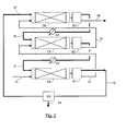
- the gas to be treated arriving via the conduit 1 flows successively into the co-current contactors C1, then C2, then C3.
- the gas and the liquid are introduced at the same end of the contactor, traverse the contactor in the same direction and in the same direction and are evacuated from the contactor by the same other end.
- the absorbent solution arriving via line 7 flows successively into contactors C3, then C2 and C1.
- the gas and the liquid circulate in co-current, that is to say that they cross the contactor, in the same direction and in the same direction.
- C1 contactors, C2 and C3 are arranged vertically and the gaseous and liquid phases pass through the contactors in the vertical direction from top to bottom.
- the absorbent solution may comprise amines in aqueous solution.
- Amines are chosen for their ability to absorb acidic compounds. It is possible to use an absorbent solution comprising, in general, between 10% and 80% by weight, preferably between 20% and 60% by weight, of amines.
- the absorbent solution may comprise between 20% and 90% by weight, preferably between 40% and 80% by weight of water.
- the absorbent solution may also contain an organic solvent which is not reactive with respect to acid gases, but which makes it possible to increase the physical solubility of an impurity, in order to improve its elimination (physical solvent).
- the amines can be chosen from monoamines such as MEA (monoethanolamine), DEA (diethanolamine), MDEA (methyldiethanolamine), DIPA (diisopropylamine), or DGA (diglycolamine), but also from multiamines such as piperazine , N- (2-hydroxyethyl) piperazine, N, N, N ', N'-tetramethylhexane-1,6-diamine, N, N, N', N'-tetraethyldiethylenetriamine, 1,2-bis ( 2-dimethylaminoethoxy) ethane, 1,2-bis (2-diethylaminoethoxy) ethane and 1,2-bis (2-pyrolidinoethoxy) ethane. These amines can be used alone, or in admixture.
- monoamines such as MEA (monoethanolamine), DEA (diethanolamine), MDEA (methyldiethanolamine), DIPA (diisopropylamine),
- the amines can also be mixed with solvents of a physical nature, for example methanol, sulpholane, polyethylene glycols which can be etherified, pyrrolydones or derivatives such as, for example, N-methylpyrrolidone, N-formyl morpholine or acetyl morpholine. , propylene carbonate.
- solvents of a physical nature for example methanol, sulpholane, polyethylene glycols which can be etherified, pyrrolydones or derivatives such as, for example, N-methylpyrrolidone, N-formyl morpholine or acetyl morpholine. , propylene carbonate.
- the absorbent solution comprises between 10% and 50% by weight of a solvent of a physical nature.
- the contactors used in the process according to the invention are provided with contacting elements, for example structured packings, for example sold under the trademark BX or Mellapak by the company.
- structured packings for example sold under the trademark BX or Mellapak by the company.
- Sulzer Chemtech or sold under the brand B1 by the company Montz or bulk packings for example marketed under the trademark IMTP by the company Koch-Glitsch, or packings described in the documents US 4,296,050 or USD379096, or static mixers for example marketed under the brand SMV by the company Sulzer Chemtech.
- packings which comprise a large geometric area, that is to say greater than 200 m 2 / m 3 , preferably greater than 300 m 2 / m 3 , or even greater than 400 m 2 / m 3 because the co-current contactors allow the use of these high specific surfaces at high flow, without risk of clogging.
- the gas to be treated arriving via line 1 is brought into contact with the liquid absorbent solution arriving via line 2 in contactor C1.
- the absorbent solution 2 comes from the contactor C2.
- the gas and the liquid circulate in C1 through a cocurrent contacting element and in the same downward vertical direction.
- the liquid absorbent solution captures the acidic compounds, in particular CO 2 and / or H 2 S contained in the gas.
- the gas is separated from the liquid, for example using gravity.
- the liquid solution loaded with acid compounds is removed from C1 by line 3.
- the gas depleted of acidic compounds is removed from C1 by line 4 to be introduced into C2.
- the gas arriving via line 4 is brought into contact with the liquid absorbent solution arriving via line 5 in contactor C2.
- the liquid absorbent solution 5 comes from the contactor C3.
- the gas and the liquid flow in C2 through a cocurrent contacting element and in the same downward vertical direction.
- the liquid absorbent solution captures the acidic compounds, in particular CO 2 and / or H 2 S contained in the gas.
- the gas is separated from the liquid, for example using gravity.
- the liquid solution loaded with acidic compounds is discharged from C2 via line 2 to be introduced into contactor C1.
- the gas depleted of acidic compounds is removed from C2 via line 6 to be introduced into C3.
- the gas arriving via line 6 is brought into contact with the liquid absorbent solution arriving via line 7 in contactor C3.
- the gas and the liquid flow through C3 through a cocurrent contacting element and a downward vertical direction.
- the liquid absorbent solution captures the acidic compounds, in particular CO 2 and / or H 2 S contained in the gas.
- the gas is separated from the liquid, for example using gravity.
- the liquid solution loaded with acidic compounds is removed from C3 via line 5 to be introduced into the contactor C2.
- the gas depleted of acidic compounds is removed from C3 via line 8.
- the absorbent solution discharged from C1 via line 3 is introduced into the regeneration section RE1 to be regenerated.
- the absorbent solution may be regenerated by being expanded and / or heated to release the acidic compounds in gaseous form.
- the acidic gaseous compounds are discharged through line 9.
- the regenerated absorbent solution is removed from RE1 via line 7 to be introduced into contactor C3.
- the process schematized by the figure 1 allows to successively contact the gas in the contactors C1, then C2 and then C3, with the absorbent solution less and less charged with acidic compounds therefore more and more efficient to absorb acidic compounds less and less concentrated. Therefore, the benefits of cocurrent flow are realized while achieving the absorption performance of the acidic compounds.
- the heat exchangers E1 and E2 disposed respectively on the ducts 2 and 5 or directly placed in the bottoms of the contactors C2 and C3, where there is a large cooling zone. contact possible to cool the absorbent solution to improve its absorption capacity. Indeed, on the one hand, the exothermicity of the absorption reaction of acidic compounds by the solution causes an increase in the temperature of the absorbent solution. On the other hand, the absorbent solution is more efficient at low temperatures.
- the process according to figure 1 to capture the CO 2 contained in fumes.
- it is adapted to the cases where one wishes to minimize the pressure drop because it makes it possible to ensure that the flow is of dripping film type, that is to say a film of liquid along the walls of the contactor with gas in the center.
- the implementation of the process according to figure 1 can be achieved by varying the number of contactors used, for example with two contactors or with three or four or more than four contactors.
- the gas to be treated arriving via the conduit 11 flows successively into the contactor C4, then C5, then C6.
- the absorbent solution arriving via line 17 flows successively into contactor C6, then C5 then C4.
- the gas and the liquid circulate in co-current, that is to say that they cross the contactor, in the same direction and in the same direction.
- the contactors C4, C5 and C6 are arranged horizontally and the gaseous and liquid phases pass through the contactors in the same horizontal direction.
- the contactors C4, C5 and C6 are provided with contacting elements, for example structured packings, for example structured packings marketed under the trademark BX or Mellapak produced by Sulzer Chemtech or marketed under the brand B1 produced by Montz. , and preferably static mixers which accept higher pressure losses, such as those mentioned in the document " Hydrodynamics and mass transfer in gas-liquid flow through static mixers, Heyouni et al., 2002, Eng Eng., Sci., 57, 3325-3333 .
- the gas to be treated arriving via line 11 is brought into contact with the liquid absorbent solution arriving via line 12 in contactor C4.
- the absorbent solution 12 comes from the contactor C5.
- the gas and the liquid circulate in C4 through a co-current contacting element and in the same horizontal direction.
- the liquid absorbent solution captures the acidic compounds, in particular CO 2 and / or H 2 S contained in the gas.
- the gas is separated from the liquid using the separator S1.
- S1 may be a separate device or included in C4.
- the liquid solution loaded with acidic compounds is removed from S1 via line 13.
- the gas depleted of acidic compounds is removed from S1 via line 14 to be introduced into C5.
- the gas arriving via line 14 is brought into contact with the liquid absorbent solution arriving via line 15 in contactor C5.
- the liquid absorbent solution 15 comes from the contactor C6.
- the gas and the liquid circulate in C5 through a co-current contacting element and in the same horizontal direction.
- the liquid absorbent solution picks up the acid compounds, in particular CO 2 and / or H 2 S contained in the gas.
- the gas is separated from the liquid using separator S2.
- S2 may be a separate device or included in C5.
- the liquid solution loaded with acidic compounds is removed from S2 via line 12 to be introduced into contactor C4.
- the gas depleted of acidic compounds is removed from S2 through line 16 to be introduced into C6.
- the gas arriving via line 16 is brought into contact with the liquid absorbent solution arriving via line 17 in contactor C6.
- the gas and the liquid circulate in C6 through a cocurrent contacting element and in the same horizontal direction.
- the liquid absorbent solution captures acidic compounds, in particular CO 2 and / or H 2 S contained in the gas.
- the gas is separated from the liquid using separator S3.
- S3 can be a separate device or included in C6.
- the liquid solution loaded with acidic compounds is removed from C6 through line 15 to be introduced into contactor C6.
- the gas depleted of acidic compounds is removed from C6 via line 18.
- the absorbent solution discharged from S1 through the conduit 13 is introduced into the regeneration section RE2 to be regenerated.
- the absorbent solution can be regenerated by being expanded and / or heated to release the acidic compounds in gaseous form.
- the acidic gaseous compounds are discharged through line 19.
- the regenerated absorbent solution is removed from RE2 via line 17 to be introduced into contactor C6.
- At least one of the heat exchangers E3 and E4 respectively disposed on the conduits 12 and 15 can be used to cool the absorbent solution or in the separation zones S1, S2, S3.
- the process according to figure 2 to capture CO 2 and / or H 2 S contained in a natural gas.
- the use of horizontal contactors operating at co-current makes it possible to circulate the gas and the liquid in hydrodynamic regimes very favorable to the transfer as in the case of a highly dispersed bubble flow, as shown in the document " Hydrodynamics and mass transfer in gas-liquid flow through static mixers, Heyouni et al., 2002, Eng Eng., Sci., 57, 3325-3333 .
- This mode of implementation generates more pressure drop and is therefore well suited to the problem of treating natural gas under pressure.
- it is less sensitive to movement than a film flow and can be interesting in the case of gas washing on platform at sea subjected to pitching and rolling.
- the implementation of the process according to figure 2 can be achieved by varying the number of contactors used, for example with two or three contactors, or with four or more contactors.
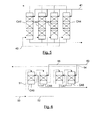
- the Figures 3 and 4 propose to recycle liquid and / or gas, from the output to the input of a contactor.
- the recycle can be implemented on one or more co-current contactors of the method according to the invention.
- recycles can be implemented in the case of vertical contactors described with reference to the figure 1 or in the case of horizontal contactors described with reference to the figure 2 .
- the absorbent solution 20 is contacted in the contactor C with the gas to be treated arriving via the conduit 21. After passing through the contactor C, the absorbent solution is discharged through the conduit 22 and the gas through the conduit 23.
- a portion of the liquid 22 may be circulated, or alternatively a portion of the gas 23 or alternatively a portion of the liquid 22 and a portion of the gas 23, from the outlet to the inlet of the contactor C.
- a portion of the liquid 22 is recycled into the contactor C.
- the liquid absorbent solution 22 is pumped by the pump P and then separated into two liquid fractions, for example by the valves V3 and V4.
- a liquid fraction is evacuated via line 26 either to supply another contactor or to supply the regenerator.
- the other liquid fraction is recycled via the conduit 27 to be introduced again at the inlet of the contactor C, for example by being mixed with the liquid flowing in the conduit 20.
- the gas 23 is divided into two gaseous fractions, for example by means of the valves V1 and V2.
- a gaseous fraction is discharged through the conduit 25.
- Another gaseous fraction is recycled via the conduit 24 to be introduced at the inlet of the contactor C, for example by being mixed with the gas flowing in the conduit 21.
- the gaseous fraction 24 can be compressed by the compressor K.
- the two recycle conduits 24 are used. 27.
- the absorbent solution 30 is contacted in the contactor C with the gas to be treated arriving via the conduit 31.
- the mixture of absorbent solution and gas is discharged through the conduit 32.
- the gas mixture and liquid 32 is divided into two fractions, for example by means of valves V5 and V6.
- a fraction of the mixture of gas and liquid is recycled via line 34 to be introduced at the inlet of contactor C.
- the fraction of the mixture of gas and liquid 34 is compressed. by the multiphase pump PP before being introduced into C.
- the other fraction of mixture of gas and liquid is introduced into the separator of gas and liquid S to produce a liquid absorbent solution discharged through line 36 and a gaseous fraction evacuated via line 35.
- the results presented in Table 1 below show the characteristics and sizing of various processes to decarbonate combustion fumes from a 630 MWe coal-fired power plant.
- the fumes to be treated have a flow rate of 1 750 000 Nm 3 / h with a composition of 13.2% volume of CO 2 .
- CO 2 capture processes with a capture rate of 90% of the CO 2 contained in the fumes are carried out thanks to the circulation of a flow rate of 8300 m 3 / h of absorbent solution composed of an aqueous solution of MEA at 30% by weight, having a respective input and output loading rate of 0.24 and 0.47.
- a case of implementation according to the prior art is compared with two cases of implementation according to the present invention. In all cases, the diameter of the columns is fixed constant and equal to 8 m.
- the stream of fumes to be treated 40 is divided into four to supply each of the four columns CA1, CA2, CA3 and CA4, inducing a gas velocity of 2.4 m / s in the columns.
- the columns are equipped with Mellapak 250.Y structured lining developing a geometric area of 250 m 2 / m 3 .
- the wetting efficiency is 80% which corresponds to an effective area, ae, of 200 m 2 / m 3 .
- the absorbent solution arriving via line 41 is split into four fractions, each supplying one of the columns CA1, CA2, CA3 and CA4.
- the required height for the contact zone in columns CA1 to CA4 is 18m, ie a total packing volume of nearly 3600 m 3 .
- This height is determined via the use of an absorber model integrating kinetics and thermodynamics models specific to a 30 wt% aqueous MEA solution and mass transfer models specific to the Mellapak 250.Y structured packing, which Thus, it is possible to calculate the reaction rates of CO 2 with the amine, the liquid-vapor equilibria and the reactive transfer.
- a first case of implementation of the method according to the invention is shown schematically by the figure 6 .
- a much more efficient packing is used which develops an effective area of 500 m 2 / m 3 while reducing the total passage section.
- the gas stream 50 is divided into two gas fractions 51 and 52 which are contacted cocurrently with an absorbent solution successively in two contactors.
- the absorbent solution arriving via line 53 is also divided into two liquid fractions 54 and 55 which are respectively contacted cocurrently with the gaseous fractions in two co-current contactors.
- the gaseous fraction 51, respectively 52 is contacted cocurrently in CA5 then CA6, respectively CA7 then CA8, with the liquid fraction 55, respectively 54.
- the height of the contactors required to achieve the same performance as those of case 1 according to the prior art is only 5.9 m, which induces a packing volume of nearly 1200 m 3 , or a reduction of almost 70% in the size of the installations.
- a second case of implementation of the method according to the invention is shown schematically by the figure 1 , in which three contactors operating at co-current and without division of the flue gas stream to be treated are used.
- contactors C1, C2 and C3 are equipped with contactors which develop an effective area, ae, of 650 m 2 / m 3 .
- This high value is obtained on the one hand because of the use of highly efficient static mixers and on the other hand by the high speeds of liquid and gas generating a large turbulence favorable to mass transfer and the creation of area interfacial.
- the gas circulation speed is increased to 9.7 m / s through the contactors C1, C2 and C3.
- the method according to the prior art requires that the flow of fumes to be treated is subdivided into several streams. , processed in parallel in dedicated columns. Operating in co-current mode according to our invention and thus to be able to pass more flow in a single column avoids or limits this subdivision.
- the scheme according to the invention makes it possible to reduce the capex (investment costs related to the number and size of the columns).
Landscapes
- Chemical & Material Sciences (AREA)
- Oil, Petroleum & Natural Gas (AREA)
- Chemical Kinetics & Catalysis (AREA)
- Engineering & Computer Science (AREA)
- General Chemical & Material Sciences (AREA)
- Organic Chemistry (AREA)
- Analytical Chemistry (AREA)
- Gas Separation By Absorption (AREA)
- Treating Waste Gases (AREA)
Abstract
Description
La présente invention concerne le domaine des procédés de désacidification d'un gaz avec une solution absorbante. L'invention porte sur la mise en contact du gaz avec la solution absorbante.The present invention relates to the field of deacidification processes of a gas with an absorbent solution. The invention relates to contacting the gas with the absorbent solution.
Dans les procédés de traitement de gaz par mise en contact du gaz avec un liquide, les procédés de distillation, de distillation réactive, de traitement ou de lavage de gaz, les transferts de masse et de chaleur entre une phase gaz et une phase liquide, sont réalisés au moyen de technologies, appelés contacteurs, qui favorisent ces transferts. Il existe trois grands types de contacteurs, les garnissages vrac, les garnissages structurés et les plateaux de colonnes. Quel que soit le choix de la technologie, le contact entre les deux phases gaz et liquide est généralement réalisé dans une colonne opérée à contre-courant, c'est-à-dire où le gaz suit un mouvement globalement vertical ascendant et le liquide suit un mouvement globalement vertical descendant. Ce mode de réalisation est imposé du fait de la volonté de mettre en contact la phase gaz de plus en plus épurée avec une solution de liquide de moins en moins chargée et ainsi de ne pas être limité par les contraintes d'équilibre thermodynamique. Dans le cas des procédés de distillation, le fractionnement de deux composants nécessite un grand nombre de plateaux théoriques d'équilibre (de l'ordre de la dizaine ou de quelques dizaines), ce qui se traduit par un nombre encore plus grand de plateaux réels dont l'efficacité est généralement proche mais généralement inférieure à 1. Dans le cas particulier du captage de CO2, ou de la désacidification d'un gaz naturel, le nombre de plateaux théoriques requis est très faible, de l'ordre de l'unité. Néanmoins il faut un grand nombre de plateaux réels du fait de la très faible efficacité des plateaux, proche de 0,1. Cette faible efficacité est due à la faible solubilité des espèces à traiter et aux fortes limitations au transfert de masse en phase gaz/vapeur et/ou en phase liquide.In gas treatment processes by contacting the gas with a liquid, distillation, reactive distillation, gas treatment or washing processes, mass and heat transfers between a gas phase and a liquid phase, are realized by means of technologies, called contactors, which favor these transfers. There are three main types of contactors, bulk packings, structured packings and column trays. Whatever the choice of the technology, the contact between the two gas and liquid phases is generally carried out in a column operated against the current, that is to say where the gas follows a globally vertical ascending movement and the liquid follows a globally vertical downward movement. This embodiment is imposed because of the desire to bring into contact the increasingly refined gas phase with a solution of less and less charged liquid and thus not to be limited by thermodynamic equilibrium stresses. In the case of distillation processes, the fractionation of two components requires a large number of theoretical equilibrium plates (of the order of ten or a few tens), which translates into an even greater number of real trays. whose efficiency is generally close but generally less than 1. In the particular case of CO 2 capture, or deacidification of a natural gas, the number of theoretical plates required is very small, of the order of unit. Nevertheless, a large number of actual trays are required because of the very low efficiency of the trays, close to 0.1. This low efficiency is due to the low solubility of the species to be treated and the strong limitations to mass transfer in the gas / vapor phase and / or in the liquid phase.
Les plateaux de colonne pour colonnes de distillation de lavage ou de traitement de gaz ont été développés depuis de nombreuses années et leur dimensionnement est bien établi pour ce qui relève de plateaux standards. Les plateaux sont essentiellement dimensionnés pour des applications de distillation et rarement pour des applications de traitement de gaz qui ne sont pas du tout limitées par les mêmes phénomènes. Dans le cas des applications de distillation, un grand nombre de plateaux théoriques, en général plusieurs dizaines, est généralement requis. Comme les équilibres thermodynamiques sont extrêmement limitant et les plateaux actuels obtiennent des efficacités proches de 100 % (cette efficacité étant le ratio entre la conversion obtenue avec le plateau réel et celle obtenue pour un plateau théorique parfaitement mélangé) il faut un grand nombre de plateaux réels, ou de grandes hauteurs de garnissages. Les phénomènes de transfert sont peu limitatifs, et le procédé est dimensionné par les aspects thermodynamiques ce qui implique une circulation des flux à contre-courant dans la colonne. Le liquide s'écoule selon un mouvement d'ensemble vertical descendant, le gaz ayant un mouvement d'ensemble ascendant vertical.Column trays for washing or gas treatment distillation columns have been developed for many years and their size is well established for standard trays. The Trays are essentially sized for distillation applications and rarely for gas processing applications that are not at all limited by the same phenomena. In the case of distillation applications, a large number of theoretical plates, generally several tens, are generally required. Since the thermodynamic equilibria are extremely limiting and the current plateaux obtain efficiencies close to 100% (this efficiency being the ratio between the conversion obtained with the real plateau and that obtained for a theoretically perfectly mixed plateau), it is necessary to have a large number of real plateaux. , or large packing heights. The transfer phenomena are not very limiting, and the process is dimensioned by the thermodynamic aspects, which implies a circulation of countercurrent flows in the column. The liquid flows in a descending vertical overall motion, the gas having a vertical upward movement.
Dans le cas du captage de CO2, et du traitement de gaz, il est courant de s'appuyer sur les bases technologiques développées pour la distillation et on retrouve donc les mêmes configurations, utilisation des mêmes technologies (plateaux, garnissages vrac, garnissages structurés..) avec une même mise en oeuvre (écoulement vertical, ascendant pour le gaz et descendant pour le liquide). Ainsi dans les ouvrages de référence traitant de la distillation et de l'absorption, seul le mode de mise en oeuvre à contre-courant est discuté. Or le nombre de plateaux théoriques requis pour des performances d'absorption sont très faibles de l'ordre de quelques unités, voire dans le cas du captage du CO2 un nombre qui peut être inférieur à 2. Il est donc intéressant de revoir les critères de dimensionnement des installations d'absorption. Ce en particulier dans le cas d'un captage de CO2 contenu dans des fumées en post-combustion par un lavage avec une solution absorbante d'amine (par exemple avec une solution aqueuse de MEA à 30 % poids), car les colonnes sont caractérisées par de très grandes dimensions, de l'ordre de 10 m de diamètre pour plus de 30 m de haut, et un coût très important. Le dimensionnement de ces colonnes est issu du respect de la meilleure efficacité possible pour un écoulement fixé à contre-courant et pour une perte de charge minimale, de l'ordre de 1 à 5 mbar/m. Les contraintes de l'écoulement des phases fixent un diamètre minimum de la colonne. Le diamètre une fois connu, il faut alors déterminer la hauteur de la colonne afin de respecter les performances recherchées. Ces performances sont en grande partie liées au coefficient de transfert de masse, kLa, variant typiquement sur une gamme d'environ 5.10-3 à 2.10-2 s-1. Ces faibles valeurs, ainsi que la faible solubilité du gaz acide dans la solution absorbante, entraînent des valeurs d'efficacité de contact entre le gaz et le liquide très faibles, variant entre 10 et 20% ce qui, malgré un faible nombre de plateaux théoriques requis, nécessite un grand nombre de plateaux réels, ou de façon équivalente, des grandes hauteurs de lits de garnissages.In the case of CO 2 capture and gas treatment, it is common practice to rely on the technological bases developed for distillation and thus find the same configurations, use of the same technologies (trays, bulk packings, structured packings ..) with the same implementation (vertical flow, ascending for the gas and descending for the liquid). Thus, in the reference works dealing with distillation and absorption, only the mode of implementation against the current is discussed. However, the number of theoretical plates required for absorption performances is very low, on the order of a few units, and even in the case of CO 2 capture, a number that may be less than 2. It is therefore interesting to review the criteria. sizing of absorption installations. This in particular in the case of a capture of CO 2 contained in post-combustion fumes by washing with an amine absorbent solution (for example with an aqueous MEA solution at 30% by weight), since the columns are characterized by very large dimensions, of the order of 10 m diameter for more than 30 m high, and a very important cost. The sizing of these columns is based on the respect of the best possible efficiency for a flow set against the current and for a minimal pressure drop, of the order of 1 to 5 mbar / m. The constraints of the flow of the phases fix a minimum diameter of the column. The diameter once known, it is then necessary to determine the height of the column to meet the desired performance. These performances are largely related to the mass transfer coefficient, k L a , typically varying over a range of about 5.10 -3 to 2.10 -2 s -1 . These low values, as well as the low solubility of the acid gas in the absorbing solution, lead to values of contact efficiency between the gas and the very low liquid, varying between 10 and 20% which, despite a small number of theoretical plates. required, requires a large number of actual trays, or equivalently, large packing bed heights.
Il faut enfin noter que la consommation énergétique requise à la mise en circulation du gaz au travers de ces colonnes peut représenter jusqu'à 10% du coût de fonctionnement de l'unité.Finally, it should be noted that the energy consumption required to put gas into circulation through these columns can represent up to 10% of the unit's operating cost.
Il est donc très intéressant de développer des mises en oeuvre et technologies associées afin de réduire les coûts d'investissement et de fonctionnement de ces procédés. C'est l'objet de la présente invention.It is therefore very interesting to develop implementations and associated technologies in order to reduce the investment and operating costs of these processes. This is the object of the present invention.
Il existe néanmoins des procédés de traitement de gaz qui fonctionnent en mode co-courant descendant, comme par exemple des unités de lavage à la soude ou le procédé RedOx d'épuration de gaz décrit dans le document
La présente invention propose une mise en oeuvre de mise en contact étagée en mode co-courant dans une succession de zone de contact qui peuvent être verticales ou horizontales avec une circulation des phases gaz et liquide en mode contre courant entre les zones de contact. Il s'agit donc de découper le procédé en plusieurs étapes, qui à l'échelle élémentaire relèvent d'une mise en contact à co-courant, et à l'échelle du procédé mettent les flux gaz et liquide en contact à contre-courant.The present invention proposes an implementation of staged contacting in co-current mode in a succession of contact zones which can be vertical or horizontal with a flow of the gas and liquid phases in counter-current mode between the contact zones. It is therefore a question of cutting the process into several stages, which on the basic scale are co-current contact, and at the process scale put the gas and liquid flows in countercurrent contact.
De manière générale, l'invention a pour objet un procédé de désacidification d'un gaz de charge comportant au moins l'un des composés acides CO2 et H2S, dans lequel on effectue les étapes suivantes :
- a) on met en contact ledit gaz de charge avec une solution absorbante liquide enrichie en composés acides produite à l'étape b) dans un premier contacteur à co-courant, le gaz de charge et la solution absorbante parcourant selon une même direction le premier contacteur depuis une entrée jusqu'à une sortie, pour produire un gaz appauvri en composés acides et une solution absorbante chargée en composés acides,
- b) on met en contact ledit gaz appauvri en composés acides avec une solution absorbante liquide dans un deuxième contacteur à co-courant, le gaz et la solution absorbante parcourant selon une même direction le deuxième contacteur depuis une entrée jusqu'à une sortie, pour produire un gaz pauvre en composés acides et ladite solution absorbante liquide enrichie en composés acides mise en oeuvre à l'étape a).
- a) said feed gas is brought into contact with an acid-enriched liquid absorbent solution produced in step b) in a first co-current contactor, the feed gas and the absorbent solution running in the same direction the first contactor from an inlet to an outlet, to produce a gas depleted of acidic compounds and an absorbent solution loaded with acidic compounds,
- b) said acid-depleted gas is brought into contact with a liquid absorbing solution in a second co-current contactor, the gas and the absorbing solution traveling in a same direction the second contactor from an input to an output, for producing a gas low in acidic compounds and said liquid absorbent solution enriched in acidic compounds implemented in step a).
Selon l'invention, on peut effectuer l'étape suivante :
- c) on met en contact ledit gaz pauvre en composés acides avec un liquide absorbant dans un troisième contacteur à co-courant, le gaz et le liquide parcourant selon une même direction le troisième contacteur depuis une entrée jusqu'à une sortie, pour produire un gaz traité et la solution absorbante liquide mise en oeuvre à l'étape b).
- c) said acid-poor gas is brought into contact with an absorbent liquid in a third co-current contactor, the gas and the liquid flowing in a same direction the third contactor from an inlet to an outlet, to produce a treated gas and the liquid absorbent solution implemented in step b).
Le gaz et le liquide peuvent parcourir les contacteurs à co-courant selon une direction verticale descendante. Alternativement, le gaz et le liquide peuvent parcourir les contacteurs à co-courant selon une direction horizontale.The gas and the liquid can travel the co-current contactors in a downward vertical direction. Alternatively, the gas and the liquid can travel the co-current contactors in a horizontal direction.
Les contacteurs peuvent comporter un garnissage qui développe une aire géométrique supérieure à 200 m2/m3 et de préférence supérieure à 400m2/m3.The contactors may comprise a lining which develops a geometric area greater than 200 m 2 / m 3 and preferably greater than 400 m 2 / m 3 .
On peut faire circuler le gaz dans les contacteurs à une vitesse supérieure à 1 m/s, de préférence supérieure à 2m/s, voire 4m/s.The gas can be circulated in the contactors at a speed greater than 1 m / s, preferably greater than 2 m / s or even 4 m / s.
On peut prélever une portion d'au moins un des deux flux choisis parmi le gaz et la solution absorbante liquide issus d'un des contacteurs, puis on peut introduire ladite portion à l'entrée dudit contacteur.A portion of at least one of the two streams chosen from the gas and the liquid absorbing solution originating from one of the contactors may be taken, and then said portion may be introduced at the inlet of said contactor.
On peut prélever une portion d'un mélange composé du gaz et de la solution absorbante issu de la sortie d'un des contacteurs, puis on peut introduire ladite portion à l'entrée dudit contacteur.A portion of a mixture composed of the gas and the absorbent solution from the outlet of one of the contactors can be taken, and then said portion can be introduced at the inlet of said contactor.
On peut augmenter la pression de ladite portion avant de l'introduire dans le contacteur.It is possible to increase the pressure of said portion before introducing it into the contactor.
Avant d'effectuer l'étape a), on peut refroidir ladite solution absorbante liquide enrichie en composés acides produite à l'étape b).Before performing step a), said acid-enriched liquid absorbent solution produced in step b) can be cooled.
On peut régénérer la solution absorbante chargée en composés acides produite à l'étape a) de manière à libérer des composés acides et produire ladite solution absorbante mise en oeuvre à l'étape b) ou ledit liquide absorbant mis en oeuvre à l'étape c).The absorbent solution loaded with acidic compounds produced in step a) can be regenerated so as to release acidic compounds and produce said absorbent solution used in step b) or said absorbent liquid used in step c. ).
La solution absorbante peut être composée d'une solution aqueuse comportant des amines.The absorbent solution may be composed of an aqueous solution comprising amines.
Le gaz de charge peut être choisi parmi l'un des gaz suivants : une fumée de combustion, un gaz naturel, un gaz obtenu en queue du procédé Claus, un gaz de synthèse, un gaz issu de la fermentation de biomasse, un effluent issu d'une cimenterie et un gaz issu d'une usine de sidérurgie.The feed gas may be chosen from one of the following gases: a combustion smoke, a natural gas, a gas obtained at the bottom of the Claus process, a synthesis gas, a gas resulting from the fermentation of biomass, an effluent resulting from a cement plant and a gas from a steel plant.
La mise en oeuvre du procédé selon l'invention est possible du fait, d'une part, de la faible limitation thermodynamique des procédés de lavage de gaz par des solutions absorbantes de type amines et, d'autre part, car, dans ces procédés, et contrairement aux cas de distillation faisant référence, on peut contrôler les débits de gaz et de liquide indépendamment (le débit de gaz est fixé par le procédé, un débit minimum de liquide y correspond mais celui-ci peut être significativement modifié si l'opérateur le souhaite). La mise en oeuvre en mode co-courant permet d'obtenir un écoulement induisant des coefficients de transfert de masse significativement supérieurs à ceux obtenus avec des plateaux ou des garnissages opérés en contre-courant. Ainsi la circulation en co-courant à l'échelle d'une colonne permet, d'une part, d'utiliser des systèmes de distribution de gaz et de liquide induisant un très bon mélange des phases sans coût énergétique sur la phase gaz et, d'autre part, d'utiliser des technologies de contact entre le gaz et le liquide très efficaces comme par exemple des mélangeurs statiques ou des garnissages à grande surface spécifique qui maintiennent une grande efficacité de contact entre les deux phases gaz et liquide. Un autre avantage majeur de la mise en circulation à co-courant est d'éviter les contraintes d'engorgement propres aux écoulements à contre-courant. En effet, dans le cas classique d'une mise en oeuvre à contre-courant, il faut faire en sorte que le diamètre de la colonne soit suffisamment grand pour limiter les vitesses des phases et assurer ainsi que le gaz ascendant ne freine le liquide descendant et inversement. Ce mode de mise en contact requiert des faibles vitesses et, donc, induit des diamètres de colonne de grandes dimensions. Afin de limiter la taille des installations fonctionnant à contre-courant, on utilise alors des garnissages assez capacitifs, c'est à dire permettant la circulation de débits importants au détriment de garnissages efficaces, qui s'engorgent plus facilement mais qui ont des efficacités de transfert de masse bien plus grandes. Dans le cas d'une mise en oeuvre à co-courant, ce problème de limitation par l'engorgement ne se pose plus et on peut utiliser des garnissages très efficaces. De plus les fortes vitesses de gaz et/ou de liquide engendrent des turbulences importantes favorables au transfert de matière.The implementation of the process according to the invention is possible because, on the one hand, of the low thermodynamic limitation of gas washing processes by amine-type absorbent solutions and, on the other hand, because in these processes and, unlike the distillation cases referred to, the flow rates of gas and liquid can be controlled independently (the gas flow rate is set by the process, a minimum flow rate of liquid corresponds to it, but this can be significantly modified if the operator wishes). The implementation in co-current mode makes it possible to obtain a flow inducing transfer coefficients mass significantly higher than those obtained with trays or packings operated against the current. Thus the co-current circulation at the scale of a column allows, on the one hand, to use gas and liquid distribution systems inducing a very good mixture of phases without energy cost on the gas phase and, on the other hand, to use very effective gas-liquid contact technologies such as static mixers or high surface area packings which maintain high contact efficiency between the two gas and liquid phases. Another major advantage of co-current circulation is to avoid bottleneck constraints specific to countercurrent flows. Indeed, in the conventional case of implementation against the current, it must be ensured that the diameter of the column is sufficiently large to limit the phase velocities and thus ensure that the ascending gas does not slow down the liquid down and vice versa. This mode of contacting requires low speeds and, therefore, induces large column diameters. In order to limit the size of the installations operating against the current, then capacitive packings are used, that is to say allowing the circulation of large flows at the expense of effective packings, which are more easily encrusted but which have efficiencies of mass transfer much bigger. In the case of a co-current implementation, this problem of limitation by waterlogging no longer arises and it is possible to use very efficient packings. In addition, the high velocities of gas and / or liquid cause significant turbulence favorable to the transfer of material.
L'invention permet ainsi une réduction importante du volume de garnissage requis au contact entre le gaz et le liquide ce qui induit un avantage économique important quant aux investissements. De plus, une mise en oeuvre en co-courant descendant (colonne verticale avec alimentation des deux phases en tête de colonne) peut permettre d'obtenir des valeurs de perte de charge bien plus faibles que celles obtenues dans le mode à contre-courant et ainsi de limiter les coûts énergétiques de mise en circulation des fluides ce qui pour certains procédés est critique.The invention thus allows a significant reduction in the volume of packing required in contact between the gas and the liquid which induces a significant economic advantage in terms of investments. In addition, a downward co-current implementation (vertical column with supply of the two phases at the top of the column) can make it possible to obtain much lower pressure drop values than those obtained in the countercurrent mode and and to limit the energy costs of circulation of fluids which for some processes is critical.
Par conséquent, la présente invention donne un avantage économique important, en particulier d'un point de vue de l'investissement.Therefore, the present invention provides a significant economic advantage, particularly from an investment point of view.
Par ailleurs, la mise en oeuvre du procédé selon l'invention permet une plus grande modularité qu'un fonctionnement traditionnel, ce qui permet d'avoir des bonnes efficacités même si les débits à traiter varient significativement.Furthermore, the implementation of the method according to the invention allows a greater modularity than a traditional operation, which allows to have good efficiencies even if the flow rates to be treated vary significantly.
En plus de son objectif de base, à savoir une réduction de volume grâce à une amélioration du contact gaz/liquide, la présente invention offre une grande souplesse d'utilisation et permet de réaliser de nombreuses possibilités à l'échelle du procédé :
- indépendance des débits de gaz et de liquide : dans le cas d'une augmentation du débit de gaz à traiter, on peut également augmenter le débit de liquide,
- possibilité de recycler du liquide : pour un débit gaz donné, on peut augmenter le débit liquide à l'échelle d'une colonne via la mise en place d'un recyclage afin notamment d'éviter des problèmes d'élévation de température ou de faciliter l'obtention d'un meilleur taux de charge,
- possibilité de mise en place d'échangeurs de chaleur classiques sur les lignes reliant deux colonnes successives ou directement en fond de colonne dans la zone assurant un temps de résidence au liquide avant entrée dans la ligne de sortie (par opposition à un cas de configuration classique qui nécessite des ajouts de moyens de collecte et de soutirage et des moyens de réinjection et de redistribution à l'intérieur des colonnes ce qui augmentent leurs hauteurs et leurs coûts).
- independence of the flow of gas and liquid: in the case of an increase of the flow of gas to be treated, one can also increase the flow of liquid,
- possibility of recycling liquid: for a given gas flow rate, it is possible to increase the liquid flow at the scale of a column via the introduction of recycling in order, in particular, to avoid problems of temperature rise or to facilitate obtaining a better charge rate,
- possibility of setting up conventional heat exchangers on the lines connecting two successive columns or directly at the bottom of the column in the zone providing a residence time for the liquid before entering the exit line (as opposed to a case of conventional configuration which requires additions of collection and withdrawal means and means of reinjection and redistribution inside the columns which increase their heights and their costs).
D'autres caractéristiques et avantages de l'invention seront mieux compris et apparaîtront clairement à la lecture de la description faite ci-après en se référant aux dessins parmi lesquels :
- la
figure 1 présente un mode de réalisation de l'invention avec trois colonnes verticales à co-courant, - la
figure 2 présente un mode de réalisation de l'invention avec trois colonnes horizontales à co-courant, - les
figures 3 schématisent le fonctionnement d'une colonne à co-courant avec recycle,et 4 - la
figure 6 représente un mode de réalisation de l'invention avec deux ensembles de deux colonnes à co-courant fonctionnant en parallèle.
- the
figure 1 presents an embodiment of the invention with three vertical co-current columns, - the
figure 2 presents an embodiment of the invention with three horizontal columns co-current, - the
Figures 3 and 4 schematize the operation of a co-current column with recycle, - the
figure 6 represents an embodiment of the invention with two sets of two co-current columns operating in parallel.
La
En référence à la
Le gaz peut être des fumées de combustion, un gaz naturel ou un gaz obtenu en queue du procédé Claus. Le gaz peut également être un gaz de synthèse, un gaz de conversion mis en oeuvre dans les centrales intégrées de combustion de charbon, de brut lourd, de bois ou de gaz naturel, un gaz issu de la fermentation de biomasse, un effluent issu d'une cimenterie ou d'une usine de sidérurgie. Le procédé selon l'invention permet de retirer les composés acides, par exemple le CO2 et/ou l'H2S, éventuellement d'autres composés acides tels que le COS, le CS2, les mercaptans. Le procédé est particulièrement bien adapté pour retirer du CO2 contenu dans des fumées de combustion.The gas may be combustion fumes, natural gas or tail gas from the Claus process. The gas may also be a synthesis gas, a conversion gas used in integrated combustion plants for coal, heavy crude, wood or natural gas, a gas resulting from the fermentation of biomass, an effluent from a cement plant or a steel plant. The process according to the invention makes it possible to remove the acidic compounds, for example CO 2 and / or H 2 S, optionally other acidic compounds such as COS, CS 2 or mercaptans. The process is particularly well suited for removing CO 2 contained in combustion fumes.
En référence à la
Selon l'invention, la solution absorbante peut comporter des amines en solution aqueuse. Les amines sont choisies pour leur capacité à absorber les composés acides. On peut mettre en oeuvre une solution absorbante comportant, en général entre 10% et 80% poids, de préférence entre 20% et 60% poids, en amines. La solution absorbante peut comporter entre 20% et 90% poids, de préférence entre 40% et 80% poids d'eau. La solution absorbante peut par ailleurs contenir un solvant organique, non réactif vis à vis des gaz acides, mais qui permet d'augmenter la solubilité physique d'une impureté, afin d'améliorer son élimination (solvant physique).According to the invention, the absorbent solution may comprise amines in aqueous solution. Amines are chosen for their ability to absorb acidic compounds. It is possible to use an absorbent solution comprising, in general, between 10% and 80% by weight, preferably between 20% and 60% by weight, of amines. The absorbent solution may comprise between 20% and 90% by weight, preferably between 40% and 80% by weight of water. The absorbent solution may also contain an organic solvent which is not reactive with respect to acid gases, but which makes it possible to increase the physical solubility of an impurity, in order to improve its elimination (physical solvent).
On peut choisir les amines parmi des monoamines telles que la MEA (monoéthanolamine), la DEA (diéthanolamine), la MDEA (méthyldiéthanolamine), la DIPA (diisopropylamine), ou la DGA (diglycolamine), mais aussi parmi des multiamines telles que la pipérazine, la N-(2-hydroxyéthyl)piperazine, la N,N,N',N'-Tétraméthylhexane-1,6-diamine, la N,N,N',N'-Tétraéthyldiéthylènetriamine, la 1,2-bis(2-diméthylaminoéthoxy)éthane, la 1,2-bis(2-diéthylaminoéthoxy)éthane et la 1,2-bis(2-pyrolidinoéthoxy)éthane. Ces amines peuvent être employées seules, ou en mélange.The amines can be chosen from monoamines such as MEA (monoethanolamine), DEA (diethanolamine), MDEA (methyldiethanolamine), DIPA (diisopropylamine), or DGA (diglycolamine), but also from multiamines such as piperazine , N- (2-hydroxyethyl) piperazine, N, N, N ', N'-tetramethylhexane-1,6-diamine, N, N, N', N'-tetraethyldiethylenetriamine, 1,2-bis ( 2-dimethylaminoethoxy) ethane, 1,2-bis (2-diethylaminoethoxy) ethane and 1,2-bis (2-pyrolidinoethoxy) ethane. These amines can be used alone, or in admixture.
Les amines peuvent également être mélangées à des solvants à caractère physique, par exemple le méthanol, le sulfolane, les polyéthylèneglycols qui peuvent être éthérifiés, les pyrrolydones ou dérivés comme par exemple la N-méthylpyrrolidone, la N-formyl morpholine, l'acétyl morpholine, le carbonate de propylène. Par exemple la solution absorbante comporte entre 10% et 50% poids d'un solvant à caractère physique.The amines can also be mixed with solvents of a physical nature, for example methanol, sulpholane, polyethylene glycols which can be etherified, pyrrolydones or derivatives such as, for example, N-methylpyrrolidone, N-formyl morpholine or acetyl morpholine. , propylene carbonate. For example, the absorbent solution comprises between 10% and 50% by weight of a solvent of a physical nature.
Les contacteurs mis en oeuvre dans le procédé selon l'invention, notamment les contacteurs C1, C2 et C3, sont munis d'éléments de mise en contact, par exemple des garnissages structurés, par exemple commercialisés sous la marque BX ou Mellapak par la société Sulzer Chemtech ou commercialisés sous la marque B1 par la société Montz, ou des garnissages vracs par exemple commercialisés sous la marque IMTP par la société Koch-Glitsch, ou des garnissages décrits dans les documents
Selon l'invention, on met de préférence en oeuvre des garnissages qui comportent une aire géométrique importante, c'est-à-dire supérieure à 200 m2/m3, de préférence supérieure à 300 m2/m3, voire supérieure à 400 m2/m3 car les contacteurs co-courant autorisent l'utilisation de ces surfaces spécifiques élevées à grand débit, sans risque d'engorgement.According to the invention, it is preferable to use packings which comprise a large geometric area, that is to say greater than 200 m 2 / m 3 , preferably greater than 300 m 2 / m 3 , or even greater than 400 m 2 / m 3 because the co-current contactors allow the use of these high specific surfaces at high flow, without risk of clogging.
Plus en détail, en référence à la
Le gaz arrivant par le conduit 4 est mis en contact avec la solution absorbante liquide arrivant par le conduit 5 dans le contacteur C2. La solution absorbante liquide 5 provient du contacteur C3. Le gaz et le liquide circulent dans C2 à travers un élément de mise en contact à co-courant et selon une même direction verticale descendante. Au cours de la mise en contact dans C2, la solution absorbante liquide capte les composés acides, notamment le CO2 et/ou l'H2S contenu dans le gaz. En fond de C2, on sépare le gaz du liquide, par exemple en utilisant la gravité. La solution liquide chargée en composés acides est évacuée de C2 par le conduit 2 pour être introduite dans le contacteur C1. Le gaz appauvri en composés acides est évacué de C2 par le conduit 6 pour être introduit dans C3.The gas arriving via
Le gaz arrivant par le conduit 6 est mis en contact avec la solution absorbante liquide arrivant par le conduit 7 dans le contacteur C3. Le gaz et le liquide circulent dans C3 à travers un élément de mise en contact à co-courant et selon une direction verticale descendante. Au cours de la mise en contact dans C3, la solution absorbante liquide capte les composés acides, notamment le CO2 et/ou l'H2S contenu dans le gaz. En fond de C3, on sépare le gaz du liquide, par exemple en utilisant la gravité. La solution liquide chargée en composés acides est évacuée de C3 par le conduit 5 pour être introduite dans le contacteur C2. Le gaz appauvri en composés acides est évacué de C3 par le conduit 8.The gas arriving via
La solution absorbante évacuée de C1 par le conduit 3 est introduite dans la section de régénération RE1 pour être régénérée. Dans RE1, la solution absorbante peut être régénérée en étant détendue et/ou en étant chauffée, pour libérer les composés acides sous forme gazeuse. Les composés acides gazeux sont évacués par le conduit 9. La solution absorbante régénérée est évacuée de RE1 par le conduit 7 pour être introduite dans le contacteur C3.The absorbent solution discharged from C1 via
Ainsi, le procédé schématisé par la
De plus, on peut mettre en oeuvre au moins un des échangeurs de chaleur E1 et E2 respectivement disposés sur les conduits 2 et 5 ou directement mis en place dans les fonds des contacteurs C2 et C3 où l'on dispose d'une importante zone de contact possible pour refroidir la solution absorbante afin d'en améliorer ses capacités d'absorption. En effet, d'une part, l'exothermicité de la réaction d'absorption de composés acides par la solution provoque une augmentation de la température de la solution absorbante. D'autre part, la solution absorbante est plus performante à basse température.In addition, it is possible to implement at least one of the heat exchangers E1 and E2 disposed respectively on the
De préférence, on utilise le procédé selon la
La mise en oeuvre du procédé selon la
En référence à la
Les contacteurs C4, C5 et C6 sont munis d'éléments de mise en contact par exemple des garnissages structurés, par exemple garnissages structurés commercialisés sous la marque BX ou Mellapak produits par la sociétés Sulzer Chemtech ou commercialisés sous la marque B1 produit par la société Montz, et de préférence des mélangeurs statiques qui acceptent de plus fortes pertes de charges, comme par exemple ceux mentionnés dans le document "
Plus en détail, le gaz à traiter arrivant par le conduit 11 est mis en contact avec la solution absorbante liquide arrivant par le conduit 12 dans le contacteur C4. La solution absorbante 12 provient du contacteur C5. Le gaz et le liquide circulent dans C4 à travers un élément de mise en contact à co-courant et selon la même direction horizontale. Au cours de la mise en contact dans C4, la solution absorbante liquide capte les composés acides, notamment le CO2 et/ou l'H2S contenu dans le gaz. Après avoir circulé à travers C4, on sépare le gaz du liquide en utilisant le séparateur S1. S1 peut être un dispositif distinct ou inclus dans C4. La solution liquide chargée en composés acides est évacuée de S1 par le conduit 13. Le gaz appauvri en composés acides est évacué de S1 par le conduit 14 pour être introduit dans C5.In more detail, the gas to be treated arriving via
Le gaz arrivant par le conduit 14 est mis en contact avec la solution absorbante liquide arrivant par le conduit 15 dans le contacteur C5. La solution absorbante liquide 15 provient du contacteur C6. Le gaz et le liquide circulent dans C5 à travers un élément de mise en contact à co-courant et selon la même direction horizontale. Au cours de la mise en contact dans C5, la solution absorbante liquide capte les composés acides, notamment le CO2 et/ou l'H2S contenu dans le gaz. Après avoir circulé à travers C5, on sépare le gaz du liquide en utilisant le séparateur S2. S2 peut être un dispositif distinct ou inclus dans C5. La solution liquide chargée en composés acides est évacuée de S2 par le conduit 12 pour être introduite dans le contacteur C4. Le gaz appauvri en composés acides est évacué de S2 par le conduit 16 pour être introduit dans C6.The gas arriving via
Le gaz arrivant par le conduit 16 est mis en contact avec la solution absorbante liquide arrivant par le conduit 17 dans le contacteur C6. Le gaz et le liquide circulent dans C6 à travers un élément de mise en contact à co-courant et selon une même direction horizontale. Au cours de la mise en contact dans C6, la solution absorbante liquide capte les composés acides, notamment le CO2 et/ou l'H2S contenu dans le gaz. Après avoir circulé à travers C6, on sépare le gaz du liquide en utilisant le séparateur S3. S3 peut être un dispositif distinct ou inclus dans C6. La solution liquide chargée en composés acides est évacuée de C6 par le conduit 15 pour être introduite dans le contacteur C6. Le gaz appauvri en composés acides est évacué de C6 par le conduit 18.The gas arriving via
La solution absorbante évacuée de S1 par le conduit 13 est introduite dans la section de régénération RE2 pour être régénérée. Dans RE2, la solution absorbante peut être régénérée en étant détendue et/ou en étant chauffée, pour libérer les composés acides sous forme gazeuse. Les composés acides gazeux sont évacués par le conduit 19. La solution absorbante régénérée est évacuée de RE2 par le conduit 17 pour être introduite dans le contacteur C6.The absorbent solution discharged from S1 through the
De plus, on peut mettre en oeuvre au moins l'un des échangeurs de chaleur E3 et E4 respectivement disposés sur les conduits 12 et 15 pour refroidir la solution absorbante ou dans les zones de séparation S1, S2, S3.In addition, at least one of the heat exchangers E3 and E4 respectively disposed on the
De préférence, on utilise le procédé selon la
La mise en oeuvre du procédé selon la
Les
En référence à la
En référence à la
Les exemples de fonctionnement présentés ci-après permettent de comparer et de montrer des avantages de l'invention par rapport à l'art antérieur.The examples of operation presented below make it possible to compare and show advantages of the invention with respect to the prior art.
Les résultats présentés dans le tableau 1 ci-dessous montrent les caractéristiques et le dimensionnement de différents procédés pour décarbonater des fumées de combustion issues d'une centrale électrique au charbon de 630 MWe. Les fumées à traiter ont un débit de 1 750 000 Nm3/h avec une composition de 13,2% volume de CO2. On met en oeuvre des procédés de captage de CO2 ayant un taux de captage de 90% du CO2 contenu dans les fumées grâce à la circulation d'un débit de 8300 m3/h de solution absorbante composée d'une solution aqueuse de MEA à 30%poids, ayant un taux de charge en entrée et en sortie respectif de 0,24 et de 0,47. On compare un cas de mise en oeuvre selon l'art antérieur avec deux cas de mise en oeuvre selon la présente invention. Dans tous les cas, le diamètre des colonnes est fixé constant et égal à 8 m.The results presented in Table 1 below show the characteristics and sizing of various processes to decarbonate combustion fumes from a 630 MWe coal-fired power plant. The fumes to be treated have a flow rate of 1 750 000 Nm 3 / h with a composition of 13.2% volume of CO 2 . CO 2 capture processes with a capture rate of 90% of the CO 2 contained in the fumes are carried out thanks to the circulation of a flow rate of 8300 m 3 / h of absorbent solution composed of an aqueous solution of MEA at 30% by weight, having a respective input and output loading rate of 0.24 and 0.47. A case of implementation according to the prior art is compared with two cases of implementation according to the present invention. In all cases, the diameter of the columns is fixed constant and equal to 8 m.
Le cas selon l'art antérieur est schématisé par la
Un premier cas de mise en oeuvre du procédé selon l'invention est schématisé par la
Un deuxième cas de mise en oeuvre du procédé selon l'invention est schématisé par la
Le tableau 1 donne les caractéristiques suivantes :
- ae : aire efficace des contacteurs en m2/m3
- N_col_Tot : nombre de colonnes mises en oeuvre dans le procédé
- H-col : hauteur du contacteur dans les colonnes en m
- Vol : volume total de contacteur installé dans les colonnes en m3
- Vsg : vitesse de circulation du gaz dans les contacteurs en m/s
- Vol. Red. : taux de réduction du contacteur par rapport au cas de l'art antérieur en %
- ae: Effective area of the contactors in m 2 / m 3
- N_col_Tot: number of columns used in the process
- H-col: height of the contactor in the columns in m
- Vol: total contactor volume installed in columns in m 3
- Vsg: speed of gas flow in the contactors in m / s
- Flight. Red. : Contactor reduction rate compared to the case of the prior art in%
Par conséquent, lorsque les quantités de gaz à traiter sont importantes, comme en particulier celui du captage de CO2 en post-combustion sur centrale thermique, le procédé selon l'art antérieur nécessite que le flux de fumées à traiter soit subdivisé en plusieurs flux, traités en parallèle dans des colonnes dédiées. Le fait de fonctionner en mode co-courant selon notre invention et donc de pouvoir passer plus de débit dans une seule colonne permet d'éviter ou de limiter cette subdivision. Par rapport au cas de mise en oeuvre selon l'art antérieur avec quatre colonnes en parallèles, on peut selon l'invention passer à trois colonnes en séries avec un fonctionnement à l'échelle de chacune des colonnes en mode co-courant, et avec un fonctionnement à l'échelle des trois colonnes en mode contre-courant. On peut également passer à une division en deux fractions en circulant dans deux colonnes en réduisant la hauteur des colonnes. En conclusion, l'exemple montre que le schéma selon l'invention permet de réduire les capex (coûts d'investissements liés aux nombre et taille des colonnes).Consequently, when the quantities of gas to be treated are large, as in particular that of CO 2 capture in post-combustion on thermal power plant, the method according to the prior art requires that the flow of fumes to be treated is subdivided into several streams. , processed in parallel in dedicated columns. Operating in co-current mode according to our invention and thus to be able to pass more flow in a single column avoids or limits this subdivision. Compared to the case of implementation according to the prior art with four columns in parallel, it is possible according to the invention to pass to three columns in series with operation at the scale of each of the columns in co-current mode, and with operation at the scale of the three columns in countercurrent mode. It can also be divided into two fractions by flowing in two columns reducing the height of the columns. In conclusion, the example shows that the scheme according to the invention makes it possible to reduce the capex (investment costs related to the number and size of the columns).
Claims (13)
Applications Claiming Priority (1)
| Application Number | Priority Date | Filing Date | Title |
|---|---|---|---|
| FR1102030A FR2977168B1 (en) | 2011-06-29 | 2011-06-29 | METHOD FOR DEACIDIFYING A GAS WITH MULTIPLE STAGES OF CONTACT WITH A CO-CURRENT WITH AN ABSORBENT SOLUTION |
Publications (1)
| Publication Number | Publication Date |
|---|---|
| EP2540376A1 true EP2540376A1 (en) | 2013-01-02 |
Family
ID=46298320
Family Applications (1)
| Application Number | Title | Priority Date | Filing Date |
|---|---|---|---|
| EP12290193A Withdrawn EP2540376A1 (en) | 2011-06-29 | 2012-06-08 | Method for deacidifying a gas with a plurality of steps of placing in co-current contact with an absorbent solution |
Country Status (2)
| Country | Link |
|---|---|
| EP (1) | EP2540376A1 (en) |
| FR (1) | FR2977168B1 (en) |
Cited By (3)
| Publication number | Priority date | Publication date | Assignee | Title |
|---|---|---|---|---|
| CN105056709A (en) * | 2015-07-30 | 2015-11-18 | 江苏金曼科技有限责任公司 | Tail gas processing method |
| US9334455B2 (en) | 2013-06-28 | 2016-05-10 | Uop Llc | Methods and apparatuses for enhanced absorption of acid gas components from sour feed gas |
| US11413571B2 (en) * | 2018-08-22 | 2022-08-16 | Exxonmobil Upstream Research Company | Removing impurities from a gas stream |
Citations (10)
| Publication number | Priority date | Publication date | Assignee | Title |
|---|---|---|---|---|
| FR1603140A (en) * | 1968-07-10 | 1971-03-22 | ||
| US4296050A (en) | 1977-05-12 | 1981-10-20 | Sulzer Brothers Ltd. | Packing element for an exchange column |
| EP0191985A2 (en) * | 1984-12-27 | 1986-08-27 | Imperial Chemical Industries Plc | Treatment of gas mixtures |
| US4741888A (en) | 1986-12-30 | 1988-05-03 | Shell Oil Company | H2 S removal from gas streams |
| EP0301623A1 (en) * | 1987-07-14 | 1989-02-01 | N.V. Nederlandse Gasunie | Process for the removal of gaseous components from a gas flow |
| US5439509A (en) * | 1991-01-22 | 1995-08-08 | Turbotak Inc. | Stripping method and apparatus |
| US6458188B1 (en) * | 2000-07-14 | 2002-10-01 | Timothy D. Mace | Method and means for air filtration |
| EP1294473B1 (en) * | 2000-06-29 | 2006-02-15 | Statoil ASA | Apparatus and method for mixing fluids |
| WO2006114502A1 (en) * | 2005-04-25 | 2006-11-02 | Verite | Large chemical and/or biological reactor for contacting two fluids and treatment facility comprising one such reactor |
| WO2010044956A1 (en) * | 2008-10-14 | 2010-04-22 | Exxonmobil Upstream Research Company | Removal of acid gases from a gas stream |
-
2011
- 2011-06-29 FR FR1102030A patent/FR2977168B1/en not_active Expired - Fee Related
-
2012
- 2012-06-08 EP EP12290193A patent/EP2540376A1/en not_active Withdrawn
Patent Citations (11)
| Publication number | Priority date | Publication date | Assignee | Title |
|---|---|---|---|---|
| FR1603140A (en) * | 1968-07-10 | 1971-03-22 | ||
| US4296050A (en) | 1977-05-12 | 1981-10-20 | Sulzer Brothers Ltd. | Packing element for an exchange column |
| US4296050B1 (en) | 1977-05-12 | 1996-04-23 | Sulzer Bros | Packing element for an exchange column |
| EP0191985A2 (en) * | 1984-12-27 | 1986-08-27 | Imperial Chemical Industries Plc | Treatment of gas mixtures |
| US4741888A (en) | 1986-12-30 | 1988-05-03 | Shell Oil Company | H2 S removal from gas streams |
| EP0301623A1 (en) * | 1987-07-14 | 1989-02-01 | N.V. Nederlandse Gasunie | Process for the removal of gaseous components from a gas flow |
| US5439509A (en) * | 1991-01-22 | 1995-08-08 | Turbotak Inc. | Stripping method and apparatus |
| EP1294473B1 (en) * | 2000-06-29 | 2006-02-15 | Statoil ASA | Apparatus and method for mixing fluids |
| US6458188B1 (en) * | 2000-07-14 | 2002-10-01 | Timothy D. Mace | Method and means for air filtration |
| WO2006114502A1 (en) * | 2005-04-25 | 2006-11-02 | Verite | Large chemical and/or biological reactor for contacting two fluids and treatment facility comprising one such reactor |
| WO2010044956A1 (en) * | 2008-10-14 | 2010-04-22 | Exxonmobil Upstream Research Company | Removal of acid gases from a gas stream |
Non-Patent Citations (1)
| Title |
|---|
| HEYOUNI ET AL.: "Hydrodynamics and mass transfer in gas-liquid flow through static mixers", CHEM. ENG. SCI., vol. 57, 2002, pages 3325 - 3333 |
Cited By (3)
| Publication number | Priority date | Publication date | Assignee | Title |
|---|---|---|---|---|
| US9334455B2 (en) | 2013-06-28 | 2016-05-10 | Uop Llc | Methods and apparatuses for enhanced absorption of acid gas components from sour feed gas |
| CN105056709A (en) * | 2015-07-30 | 2015-11-18 | 江苏金曼科技有限责任公司 | Tail gas processing method |
| US11413571B2 (en) * | 2018-08-22 | 2022-08-16 | Exxonmobil Upstream Research Company | Removing impurities from a gas stream |
Also Published As
| Publication number | Publication date |
|---|---|
| FR2977168A1 (en) | 2013-01-04 |
| FR2977168B1 (en) | 2015-07-24 |
Similar Documents
| Publication | Publication Date | Title |
|---|---|---|
| CA3001479C (en) | Compact subsea dehydration | |
| EP2445614B1 (en) | Process for the treatment of acid gases | |
| KR101847805B1 (en) | Contacting a gas stream with a liquid stream | |
| EP2193833B1 (en) | Method for deacidifying a gas by an absorbing solution with demixing during regeneration | |
| EP3017857B1 (en) | Method for deacidifying a gaseous effluent with an absorbent solution with steam injection in the regenerated absorbent solution and device for implementing same | |
| JP6952807B2 (en) | Small contact systems and methods for capturing sulfur-containing compounds | |
| FR2938454A1 (en) | Acid compound e.g. carbon dioxide, capturing method for gas to be treated, involves allowing gas enriched with acid compounds to be in contact in washing section, and recycling part of water enriched in amine | |
| EP2540376A1 (en) | Method for deacidifying a gas with a plurality of steps of placing in co-current contact with an absorbent solution | |
| WO2018114696A1 (en) | Column for the exchange of matter and/or heat between a gas and a liquid with means for recirculating the liquid and use of same | |
| FR2896509A1 (en) | Mercaptan e.g. methyl mercaptan, capturing method for use during deacidification of natural gas, involves circulating purge gas across molecular sieve to obtain gas that is contacted with solvent so that mercaptans are absorbed by solvent | |
| US20200061523A1 (en) | Removing Impurities From A Gas Stream | |
| EP2480315B1 (en) | Process of deacidification of a gas stream by an absorbing solution with elimination of cos by catalytic hydrolysis | |
| FR2961115A1 (en) | Method for capturing e.g. carbon dioxide compounds contained in natural gas to limit global warming phenomenon, involves making gas fractions to be in contact with absorbing solution fractions in absorbing sections arranged in same column | |
| WO2013064755A1 (en) | Method for deacidifying a gas using a plurality of steps for cross-flow contact with an absorbent solution | |
| FR2958180A1 (en) | Capturing acid compounds comprising carbon dioxide and hydrogen sulfide contained in e.g. natural gas, comprises contacting gas with absorbent solution, and regenerating fraction of absorbent solution enriched in acid compounds | |
| CA1339242C (en) | Process and means for eliminating low content h s present in a gas also containing an important quantity of water vapour | |
| US10315154B2 (en) | Method for the recovery of carbon dioxide from an absorbent with reduced supply of stripping steam | |
| FR2983737A1 (en) | Method for deacidification of gas load, involves arranging contact zone with monolith contactor with two juxtaposed channels, where channels are closed and are provided with openings at end of monolith contactor | |
| OA20253A (en) | Column for the exchange of material and/or heat between a gas and a liquid with means for recirculating the liquid and its use | |
| EP4267278A1 (en) | Method for capturing a molecule of interest and associated capture system | |
| RU2627847C2 (en) | Method and column of absorption purification of gases from unintended impurities | |
| FR2979550A1 (en) | Device for deacidification of e.g. flue gas with acid compounds, has liquid collection unit placed in absorption column, and pipe for establishing communication with liquid collection unit, where pipe plunges in tank | |
| FR3024047A1 (en) | INSTALLATION AND METHOD FOR DEACIDIFYING GAS BY AN ABSORBENT SOLUTION WITH OPTIMIZED WASHING SECTION |
Legal Events
| Date | Code | Title | Description |
|---|---|---|---|
| PUAI | Public reference made under article 153(3) epc to a published international application that has entered the european phase |
Free format text: ORIGINAL CODE: 0009012 |
|
| AK | Designated contracting states |
Kind code of ref document: A1 Designated state(s): AL AT BE BG CH CY CZ DE DK EE ES FI FR GB GR HR HU IE IS IT LI LT LU LV MC MK MT NL NO PL PT RO RS SE SI SK SM TR |
|
| AX | Request for extension of the european patent |
Extension state: BA ME |
|
| 17P | Request for examination filed |
Effective date: 20130702 |
|
| RBV | Designated contracting states (corrected) |
Designated state(s): AL AT BE BG CH CY CZ DE DK EE ES FI FR GB GR HR HU IE IS IT LI LT LU LV MC MK MT NL NO PL PT RO RS SE SI SK SM TR |
|
| 17Q | First examination report despatched |
Effective date: 20170818 |
|
| RAP1 | Party data changed (applicant data changed or rights of an application transferred) |
Owner name: IFP ENERGIES NOUVELLES |
|
| GRAP | Despatch of communication of intention to grant a patent |
Free format text: ORIGINAL CODE: EPIDOSNIGR1 |
|
| RIC1 | Information provided on ipc code assigned before grant |
Ipc: B01D 53/18 20060101ALI20190625BHEP Ipc: C10L 3/10 20060101ALI20190625BHEP Ipc: B01D 53/14 20060101AFI20190625BHEP |
|
| INTG | Intention to grant announced |
Effective date: 20190726 |
|
| STAA | Information on the status of an ep patent application or granted ep patent |
Free format text: STATUS: THE APPLICATION IS DEEMED TO BE WITHDRAWN |
|
| 18D | Application deemed to be withdrawn |
Effective date: 20191206 |