EP2540332A2 - Inhaler - Google Patents
Inhaler Download PDFInfo
- Publication number
- EP2540332A2 EP2540332A2 EP12186387A EP12186387A EP2540332A2 EP 2540332 A2 EP2540332 A2 EP 2540332A2 EP 12186387 A EP12186387 A EP 12186387A EP 12186387 A EP12186387 A EP 12186387A EP 2540332 A2 EP2540332 A2 EP 2540332A2
- Authority
- EP
- European Patent Office
- Prior art keywords
- blister
- airflow
- housing
- mouthpiece
- piercing
- Prior art date
- Legal status (The legal status is an assumption and is not a legal conclusion. Google has not performed a legal analysis and makes no representation as to the accuracy of the status listed.)
- Withdrawn
Links
Images


Classifications
-
- A—HUMAN NECESSITIES
- A61—MEDICAL OR VETERINARY SCIENCE; HYGIENE
- A61M—DEVICES FOR INTRODUCING MEDIA INTO, OR ONTO, THE BODY; DEVICES FOR TRANSDUCING BODY MEDIA OR FOR TAKING MEDIA FROM THE BODY; DEVICES FOR PRODUCING OR ENDING SLEEP OR STUPOR
- A61M15/00—Inhalators
-
- A—HUMAN NECESSITIES
- A61—MEDICAL OR VETERINARY SCIENCE; HYGIENE
- A61M—DEVICES FOR INTRODUCING MEDIA INTO, OR ONTO, THE BODY; DEVICES FOR TRANSDUCING BODY MEDIA OR FOR TAKING MEDIA FROM THE BODY; DEVICES FOR PRODUCING OR ENDING SLEEP OR STUPOR
- A61M15/00—Inhalators
- A61M15/0028—Inhalators using prepacked dosages, one for each application, e.g. capsules to be perforated or broken-up
- A61M15/0045—Inhalators using prepacked dosages, one for each application, e.g. capsules to be perforated or broken-up using multiple prepacked dosages on a same carrier, e.g. blisters
-
- A—HUMAN NECESSITIES
- A61—MEDICAL OR VETERINARY SCIENCE; HYGIENE
- A61M—DEVICES FOR INTRODUCING MEDIA INTO, OR ONTO, THE BODY; DEVICES FOR TRANSDUCING BODY MEDIA OR FOR TAKING MEDIA FROM THE BODY; DEVICES FOR PRODUCING OR ENDING SLEEP OR STUPOR
- A61M15/00—Inhalators
- A61M15/0001—Details of inhalators; Constructional features thereof
- A61M15/0021—Mouthpieces therefor
- A61M15/0025—Mouthpieces therefor with caps
-
- A—HUMAN NECESSITIES
- A61—MEDICAL OR VETERINARY SCIENCE; HYGIENE
- A61M—DEVICES FOR INTRODUCING MEDIA INTO, OR ONTO, THE BODY; DEVICES FOR TRANSDUCING BODY MEDIA OR FOR TAKING MEDIA FROM THE BODY; DEVICES FOR PRODUCING OR ENDING SLEEP OR STUPOR
- A61M15/00—Inhalators
- A61M15/0028—Inhalators using prepacked dosages, one for each application, e.g. capsules to be perforated or broken-up
- A61M15/003—Inhalators using prepacked dosages, one for each application, e.g. capsules to be perforated or broken-up using capsules, e.g. to be perforated or broken-up
- A61M15/0033—Details of the piercing or cutting means
- A61M15/0035—Piercing means
-
- A—HUMAN NECESSITIES
- A61—MEDICAL OR VETERINARY SCIENCE; HYGIENE
- A61M—DEVICES FOR INTRODUCING MEDIA INTO, OR ONTO, THE BODY; DEVICES FOR TRANSDUCING BODY MEDIA OR FOR TAKING MEDIA FROM THE BODY; DEVICES FOR PRODUCING OR ENDING SLEEP OR STUPOR
- A61M15/00—Inhalators
- A61M15/0028—Inhalators using prepacked dosages, one for each application, e.g. capsules to be perforated or broken-up
- A61M15/003—Inhalators using prepacked dosages, one for each application, e.g. capsules to be perforated or broken-up using capsules, e.g. to be perforated or broken-up
- A61M15/0033—Details of the piercing or cutting means
- A61M15/0041—Details of the piercing or cutting means with movable piercing or cutting means
-
- A—HUMAN NECESSITIES
- A61—MEDICAL OR VETERINARY SCIENCE; HYGIENE
- A61M—DEVICES FOR INTRODUCING MEDIA INTO, OR ONTO, THE BODY; DEVICES FOR TRANSDUCING BODY MEDIA OR FOR TAKING MEDIA FROM THE BODY; DEVICES FOR PRODUCING OR ENDING SLEEP OR STUPOR
- A61M15/00—Inhalators
- A61M15/0028—Inhalators using prepacked dosages, one for each application, e.g. capsules to be perforated or broken-up
- A61M15/0045—Inhalators using prepacked dosages, one for each application, e.g. capsules to be perforated or broken-up using multiple prepacked dosages on a same carrier, e.g. blisters
- A61M15/0046—Inhalators using prepacked dosages, one for each application, e.g. capsules to be perforated or broken-up using multiple prepacked dosages on a same carrier, e.g. blisters characterized by the type of carrier
- A61M15/0051—Inhalators using prepacked dosages, one for each application, e.g. capsules to be perforated or broken-up using multiple prepacked dosages on a same carrier, e.g. blisters characterized by the type of carrier the dosages being arranged on a tape, e.g. strips
-
- A—HUMAN NECESSITIES
- A61—MEDICAL OR VETERINARY SCIENCE; HYGIENE
- A61M—DEVICES FOR INTRODUCING MEDIA INTO, OR ONTO, THE BODY; DEVICES FOR TRANSDUCING BODY MEDIA OR FOR TAKING MEDIA FROM THE BODY; DEVICES FOR PRODUCING OR ENDING SLEEP OR STUPOR
- A61M15/00—Inhalators
- A61M15/0065—Inhalators with dosage or measuring devices
- A61M15/0068—Indicating or counting the number of dispensed doses or of remaining doses
- A61M15/007—Mechanical counters
- A61M15/0071—Mechanical counters having a display or indicator
- A61M15/0078—Mechanical counters having a display or indicator on a strip
-
- A—HUMAN NECESSITIES
- A61—MEDICAL OR VETERINARY SCIENCE; HYGIENE
- A61M—DEVICES FOR INTRODUCING MEDIA INTO, OR ONTO, THE BODY; DEVICES FOR TRANSDUCING BODY MEDIA OR FOR TAKING MEDIA FROM THE BODY; DEVICES FOR PRODUCING OR ENDING SLEEP OR STUPOR
- A61M15/00—Inhalators
- A61M15/0086—Inhalation chambers
-
- A—HUMAN NECESSITIES
- A61—MEDICAL OR VETERINARY SCIENCE; HYGIENE
- A61M—DEVICES FOR INTRODUCING MEDIA INTO, OR ONTO, THE BODY; DEVICES FOR TRANSDUCING BODY MEDIA OR FOR TAKING MEDIA FROM THE BODY; DEVICES FOR PRODUCING OR ENDING SLEEP OR STUPOR
- A61M15/00—Inhalators
- A61M15/0091—Inhalators mechanically breath-triggered
-
- A—HUMAN NECESSITIES
- A61—MEDICAL OR VETERINARY SCIENCE; HYGIENE
- A61M—DEVICES FOR INTRODUCING MEDIA INTO, OR ONTO, THE BODY; DEVICES FOR TRANSDUCING BODY MEDIA OR FOR TAKING MEDIA FROM THE BODY; DEVICES FOR PRODUCING OR ENDING SLEEP OR STUPOR
- A61M2202/00—Special media to be introduced, removed or treated
- A61M2202/06—Solids
- A61M2202/064—Powder
Definitions
- the present invention relates to an inhalation device for oral or nasal delivery of medicament in powdered form.
- the invention also relates to an inhaler containing a strip of blisters each having a puncturable lid and containing a dose of medicament for inhalation by a user of the device according to the invention and, to a method of using such a device.
- Oral or nasal delivery of a medicament using an inhalation device is a particularly attractive method of drug administration as these devices are relatively easy for a patient to use discreetly and in public.
- medicament to treat local diseases of the airway and other respiratory problems, they have more recently also been used to deliver drugs to the bloodstream via the lungs thereby avoiding the need for hypodermic injections.
- the powdered medicament is held in a reservoir within a dispensing device that is operable to measure out and dispense a predetermined amount of powder for each dose.
- a dispensing device that is operable to measure out and dispense a predetermined amount of powder for each dose.
- these devices suffer from poor dose metering capability especially when the size of the dose is relatively small as it is difficult to accurately measure out small amounts of dry powder in such a device. It is also difficult to protect the drug from the ingress of moisture and to seal it from the atmosphere until it is required for administration to a patient.
- a blister is generally cold formed from a ductile foil laminate or a plastics material and includes a puncturable lid which is permanently heat-sealed around the periphery of the blister during manufacture and after introduction of the dose into the blister.
- a foil blister is preferred over capsules as each dose is protected from the ingress of water and penetration of gases such as oxygen in addition to being shielded from light and UV radiation all of which can have a detrimental effect on the delivery characteristics of the inhaler if a dose becomes exposed to them. Therefore, a blister offers excellent environmental protection to each individual drug dose.
- Inhalation devices that receive a blister pack comprising a number of blisters each of which contain a pre-metered and individually packaged dose of the drug to be delivered are known. Actuation of the device causes a mechanism to open a blister so that when the patient inhales, air is drawn through the blister entraining the dose therein that is then carried out of the blister through the device and via the patient's airway down into the lungs.
- the inhaler it is advantageous for the inhaler to be capable of holding a number of doses to enable it to be used repeatedly over a period of time without the requirement to open and/or insert a blister into the device each time it is used. Therefore, many conventional devices include means for storing a number of blisters each containing an individual dose of medicament. When a dose is to be inhaled, an indexing mechanism moves a previously emptied blister away from the opening mechanism so that a fresh one is moved into a position ready to be opened for inhalation of its contents.
- a problem with conventional inhalation devices is that they are relatively large, heavy and difficult to operate. Despite their large size, many of them only have sufficient capacity to hold a relatively small number of doses before the device must be opened and a fresh set of blisters mounted therein. Although it may be possible to increase the number of blisters by making them smaller, this can only be achieved at the expense of reducing the dose payload or capacity of each blister. This is particularly disadvantageous when the device is to be used to deliver for example newer, less potent drugs where each blister must be able to hold a payload of somewhere in the region of 10-20mg of the drug.
- a conventional inhalation device of the type described above is known from US 4,811, 731 .
- This device is configured to receive a disc-shaped dose storage blister pack in which the doses are arranged in a generally circular pattern.
- a plunger is provided which moves in response to the actuation of a lever to puncture a blister disposed beneath it to enable the dose to be inhaled from the punctured blister.
- the device also includes a separate indexing device operable to rotate the disc so as to move a fresh blister to a puncturable position.
- a significant problem with this device is that the number of doses is severely limited. As can be seen from the device shown in the Figures, it is capable of receiving only eight doses at a time so frequent replacement of the disc is necessary.
- the disc can be made larger to accommodate a larger number of blisters, this would result in a significant increase in the overall size of the device making it very bulky. It is also notable that the piercing and indexing steps are controlled entirely independently of each other making the device significantly harder to use and increasing the number of components forming the device.
- US 6,032,666 Another known inhalation device is described in US 6,032,666 . Although this device receives a strip of blisters, it has a very complicated construction with numerous components making it hard to assemble and operate. It is limited by the fact that access to the dose contained in each blister is obtained by peeling the lid off it rather than by piercing it. Therefore, the device has a complicated mechanism for peeling the lid from the blister including a take-up spool for the peeled lid strip and a complex clutch arrangement to ensure that the same length of lid is peeled from the strip each time the device is used as more and more of the lid strip is wound around the take-up spool.
- this device can only be used with a strip of blisters in which the lid is peelably attached to the blister. Not only does this require a suitable adhesive, it also reduces the barrier to moisture and other environmental contaminants.
- the present invention seeks to provide an inhalation device that overcomes or substantially alleviates the problems with conventional inhalation devices of the type discussed above.
- the invention seeks to provide a device having a significantly simpler construction than known devices that is capable of storing a relatively large number of blisters that are also capable of containing a large payload without any significant increase in the overall size of the device.
- the inhalation device of the present invention should also be much easier to make, assemble and operate as well as being cheaper to manufacture.
- an inhaler comprising a housing to receive a plurality of blisters each having a puncturable lid and containing a dose of medicament for inhalation by a user, a mouthpiece through which a dose of medicament is inhaled by a user and, an actuator operable to sequentially move each blister into alignment with a blister piercing member, said actuator also being operable to cause the blister piercing member to puncture the lid of a blister such that, when a user inhales through the mouthpiece, an airflow through the blister is generated to entrain the dose contained therein and carry it out of the blister and via the mouthpiece into the user's airway.
- the actuator is pivotally mounted to the housing and may comprise an arm which may be pivotally mounted to the housing at one end.
- the blister piercing member may comprise a pair of piercing heads depending from one side of said arm positioned so as to extend through the aperture in the housing in a closed position, in which the arm lies substantially against the housing, to pierce the lid of a blister aligned with the aperture.
- Each piercing head may preferably comprise a primary cutting element and a pair of secondary cutting elements extending laterally across each end of the primary cutting element.
- the primary cutting element and the secondary cutting elements each have a pointed tip, the tip of the primary cutting element extending beyond the tips of each of the secondary cutting elements.
- the secondary cutting elements are parallel to each other and extend at right angles to the primary cutting element, although the secondary elements need not be parallel and could extend from the primary cutting element at any convenient angle.
- an opening is formed in the arm in the vicinity of each piercing head, at least one of said openings forming an airflow inlet into a blister and, at least one other of said openings forming an airflow outlet from a blister.
- the secondary cutting elements upstand from the edge or periphery of said opening in the arm and the primary cutting element extends across the opening and joins each of the secondary cutting elements together.
- the mouthpiece is on the arm and extends in a direction opposite to the direction in which the piercing heads extend, the openings in the arm being in communication with the inside of the mouthpiece.
- the mouthpiece, the arm and the piercing heads are integrally formed, although the piercing heads may also be formed on a separate piercing module that is removably mountable on the arm or is at least separately attachable to the arm during manufacture.
- the mouthpiece preferably includes a primary chamber having an outside air inlet in communication, via the primary chamber, with the or each airflow inlet opening in the arm and, a secondary chamber in communication with the or each airflow outlet opening in said arm such that, when a user inhales through the mouthpiece, air is drawn through the or each airflow inlet opening into the blister via the outside air inlet and the primary chamber to entrain the dose in the airflow, said entrained dose passing through the or each airflow outlet openings into the secondary chamber of the mouthpiece from where it is carried into the user's airway.
- a partitioning wall may separate the primary and secondary chambers within the mouthpiece and at least one air bypass aperture may extend through the partitioning wall to communicate the primary chamber with the secondary chamber.
- the or each bypass aperture may be configured such that the airflow from the primary chamber into the secondary chamber through the or each bypass aperture and the airflow from the or each airflow outlet openings meet substantially at right angles to each other. As the flows meet at an angle, the degree of turbulence is increased which assists in the deagglomeration of the dose and the creation of an inhalable aerosol.
- the inhaler includes an indexing mechanism including an indexing member that moves so as to move a blister into alignment with the blister piercing member.
- the indexing member is a wheel which rotates so as to move a blister into alignment with the blister piercing member.
- other arrangements are possible such as, for example, a mechanism that incorporates a sliding or reciprocating member.
- the inhaler is configured so that indexing of the blister strip occurs when the actuator is pivoted in one direction and piercing of a blister occurs when it is rotated in the opposite direction.
- the device can also be configured so that the indexing wheel rotates, to move a blister into alignment with said blister piercing member, in response to rotation of the actuator with respect to the housing in one direction, movement of the actuator in the same direction also being operable to puncture the lid of a blister aligned with the blister piercing member.
- the indexing wheel and the actuator include co-operating means thereon that engages when the actuator is rotated in one direction to cause rotation of the indexing wheel.
- the cooperating means comprise a set of ratchet teeth on the indexing wheel and a drive pawl on the actuator.
- means depend from the housing to substantially prevent rotation of the indexing wheel other than by movement of the actuator in said one direction.
- said means comprises a first resiliently deformable anti-rotation pawl on the housing that extends into one of said recesses in the indexing wheel, the actuator including means for deflecting the first anti-rotation pawl from the recess to permit rotation of the indexing wheel when the drive pawl engages with the ratchet teeth.
- the actuator may include a drive plate and the means on the actuator for deflecting the first anti-rotation pawl comprises a release pin upstanding from the drive plate that engages with and resiliently deflects the pawl out of the recess to allow rotation of the indexing wheel.
- the inhaler may also comprise a second resiliently deformable anti-rotation pawl on the housing and a cam member on the actuator, the cam member engaging with a cam surface on the second anti-rotation pawl when the first anti-rotation pawl is deflected out of a recess to prevent rotation of the indexing wheel through more than a predetermined angle.
- the inhaler may include a cap attached to the housing pivotable between a closed position in which it covers the actuator and mouthpiece and an open position in which the actuator and mouthpiece are revealed to enable a user to inhale through the mouthpiece.
- the indexing wheel rotates to move a blister into alignment with the blister piercing member in response to rotation of the cap with respect to the housing from the open to the closed position.
- the cap and the actuator include co-operating means to couple the actuator to the cap such that the actuator rotates relative to the housing in response to rotation of the cap between the open and closed positions.
- the cooperating means may comprise a cam guide slot on the cap and a cam follower on the actuator slideably located within the cam guide slot.
- the cam guide slot is shaped such that when the cap is rotated from its closed to its open position, the cam follower travels along the cam guide slot to rotate the actuator and cause the blister piercing member to pierce a blister aligned therewith the aperture and, when the cap is rotated from its open to its closed position, the cam travels back along the cam guide slot to cause the actuator to rotate in the opposite direction and withdraw the piercing member from the blister.
- the cam guide slot may be configured so that the actuator does not rotate until towards the end of the movement of the cap from its closed to its open position and rotates at the beginning of the movement of the cap from its open to its closed position.
- the indexing wheel and the cap each include a toothed gear member mounted thereon engaged such that rotation of the cap between the open and closed positions causes rotation of the gear member on the indexing wheel.
- a clutch member preferably couples the gear member on the indexing wheel to the indexing wheel such that the indexing wheel rotates together with the gear member coupled thereto when the cap is rotated from the open to the closed position to move a subsequent blister into alignment with the blister piercing member.
- the housing advantageously includes a chamber to receive used blisters.
- the chamber may be covered by a lid attached to the housing which is openable to facilitate removal of a portion of used blisters from the blisters remaining in the device.
- a separating element is mounted on the housing, which is operable to enable detachment of said portion of used blisters.
- the separating element preferably includes a resilient blister grip that is operable to press a blister strip against the housing to facilitate separation of said portion from said remaining blisters.
- the inhaler according to the invention may also incorporate a coiled strip of blisters, each having a puncturable lid and containing a dose of medicament for inhalation by a user, located in the housing.
- a method of using an inhaler including the step of rotating the actuator to move a blister into alignment with a blister piercing member in the housing and to puncture the lid of a blister aligned with the blister piercing member and, inhaling through the mouthpiece to generate an airflow through the blister to entrain the dose contained therein and carry it through the aperture and via the mouthpiece into the user's airway.
- the step of rotating the actuator may include the step of rotating it in a first direction to puncture the lid of a blister aligned with the blister piercing member and, once the inhalation step is complete, rotating it in a second direction to move a subsequent blister into alignment with the blister piercing member in the housing. Additionally, the step of rotating the actuator may comprise the step of rotating a cap coupled to the actuator.
- an inhaler comprising a housing to receive a blister having a puncturable lid and containing a dose of medicament for inhalation by a user, the device comprising a piercing head for puncturing the lid of a blister so that the dose contained therein can be inhaled by the user from the blister through the device, wherein the piercing head comprises a primary cutting element which is configured to cut, as the piercing head enters the blister, a first linear slit in the lid and, secondary cutting elements extending laterally from the primary cutting element which are configured to cut, as the piercing head continues to enter the blister, second linear slits that extend across each end of the first linear slit formed by the primary cutting element, the primary and secondary cutting elements together forming a pair of flaps in the lid which are folded aside by the piercing head upon further entry of the piercing head into the blister.
- the inhaler may be capable of receiving just a single blister. However, in a preferred embodiment, it receives a strip of blisters each containing a dose of medicament.
- the inhaler may include a blister strip indexing mechanism, such as those described with reference to other embodiments of the invention, which is operable to cause the blister strip to sequentially index the blisters into a position in which each blister will be pierced by the piercing head.
- the piercing head comprises a pair of secondary cutting elements.
- the secondary cutting elements may be spaced from each other and the primary cutting element is mounted on and extends between said pair of secondary cutting elements.
- the primary cutting element is formed from a blade, the plane of the blade lying substantially at right angles to a plane occupied by the lid of a blister, which is located in the inhaler in a position ready for piercing.
- the primary cutting element advantageously has a sharpened edge for cutting the first linear slit in the lid of the blister.
- the edge may taper towards a pointed tip which may be located midway between the secondary cutting elements.
- the secondary piercing elements are positioned so that they each extend laterally across either end of the primary piercing element.
- Each of the secondary piercing elements may be formed from a blade, the plane of the blade lying substantially at right angles to the plane of the blade forming the primary piercing element and at right angles to the lid of a blister located in a piercing position. As with the primary piercing element, each of the secondary piercing elements may have a sharpened edge to cut the second linear slits in the lid of a blister.
- each of the secondary piercing elements taper to a pointed tip.
- the pointed tip of each of the secondary piercing elements lie in the plane occupied by the primary piercing element.
- the pointed tip of each of the secondary piercing elements lie at the same height as the primary piercing element at the point at which the primary piercing element and secondary piercing element meet each other.
- the primary cutting element divides each secondary cutting element into first and second cutting members that extend laterally from opposite sides of the primary cutting element.
- the first and second cutting members converge towards each other at an angle and the primary cutting element upstands from the top of the secondary cutting members from a point on each secondary cutting element at which the first and second cutting members meet.
- the secondary cutting elements may be angled inwardly towards each other to assist in the formation and folding of the flaps in the lid of the blister as the piercing head enters the blister.
- the inhaler preferably comprises a pair of piercing heads upstanding from a piercing member.
- the primary and secondary cutting elements are integrally moulded in one piece.
- the secondary cutting elements extend laterally from the primary cutting element at an angle of 90 degrees to the primary cutting element.
- the secondary cutting elements may extend laterally from the primary cutting element at an angle of less than, or more than, 90 degrees.
- the primary cutting element preferably divides each of the secondary cutting elements into secondary cutting members that extend laterally from the primary cutting element by different distances so that the flap cut in the lid of a blister by the secondary cutting members extending laterally from one side of the primary cutting element is of a different size to the flap cut in the blister by the secondary cutting members that extend laterally from the other side of the primary cutting member.
- the piercing member may comprise a discrete piercing module which is moulded separately and then subsequently attached to the actuator either permanently during assembly or so that it may be removed from the actuator by the user for replacement, if necessary.
- the piercing module conveniently comprises a main body portion with first and second piercing heads upstanding therefrom.
- an air inlet and an air outlet aperture extends through the main body portion of the piercing module, one of the piercing heads depending from the periphery of the air inlet and extending over the air inlet and the other piercing head depending from the periphery of the air outlet and extending over the air outlet.
- the main body portion may include a recessed region around the air inlet, the piercing head depending from the periphery of the air inlet from the recessed region.
- the air outlet aperture is preferably in communication with an air outlet tube extending from the main body in an opposite direction to the piercing head extending from the periphery of the air outlet aperture.
- the air outlet tube comprises axially extending ridges formed on its outer surface, which locate the piercing head within a walled recess in the mouthpiece.
- a space formed between the ridges and the walled recess advantageously comprises a bypass air conduit for the direct flow of air into the mouthpiece from outside when a patient inhales through the mouthpiece.
- the indexing mechanism comprises a blister strip locator chassis defining a path for the strip of blisters past the aperture in the housing.
- a resiliently deformable arm extends from the blister strip locator chassis and the indexing mechanism comprises an indexing wheel rotatably mounted to the free end of the resiliently deformable arm over which a strip of blisters is passed.
- the indexing wheel may comprise a set of spokes and the actuator includes a drive tooth engageable with a first spoke when the actuator is pivoted relative to the housing into an open position to cause the indexing wheel to rotate together with the actuator to index the blister strip.
- the inhaler includes an anti-rotation ramp on the housing which is engaged by another spoke of the indexing wheel when the indexing wheel rotates thereby causing the arm to deform to allow said spoke to clear the anti-rotation ramp, the arm returning to its undeformed state once the spoke has cleared the ramp, thereby preventing rotation of the indexing wheel in the opposite direction.
- the drive tooth on the actuator is shaped so that, when the actuator is rotated in the opposite direction from its open into its closed position, the drive tooth slides over the top of the preceding spoke of the indexing wheel.
- each spoke is shaped to allow the drive tooth to pass over it when the actuator is pivoted from its open into its closed position.
- a location ramp may be positioned adjacent to but spaced from the anti-rotation ramp.
- the drive tooth may be operable to cause the arm to resiliently deform as the drive tooth slides over the top of the spoke to cause another spoke of the indexing wheel to extend into the space between the anti-rotation and location ramps and prevent rotation of the indexing wheel in either direction.
- an inhaler comprising a housing to receive a single blister having a puncturable lid and containing a dose of medicament for inhalation by a user, a mouthpiece through which a dose of medicament is inhaled by a user, a blister piercing member and, an actuator pivotally mounted to the housing and operable to cause the blister piercing member to puncture the lid of a blister received in the housing such that, when a user inhales through the mouthpiece, an airflow through the blister is generated to entrain the dose contained therein and carry it out of the blister and via the mouthpiece into the user's airway.
- the blister piercing member comprises at least two discrete piercing heads operable to pierce a corresponding number of holes in a blister received in the housing, the actuator comprising an arm pivotally mounted to the housing at one end and an opening being formed in the arm in the vicinity of each piercing head, at least one of said openings forming an airflow inlet into a blister and, at least one other of said openings forming an airflow outlet from a blister, the mouthpiece including a primary chamber having an outside air inlet in communication, via the primary chamber, with the or each airflow inlet opening and, a secondary chamber in communication with the or each airflow outlet opening such that, when a user inhales through the mouthpiece, air is drawn through the or each airflow inlet opening into the blister via the outside air inlet and the primary chamber to entrain the dose in the airflow, said entrained dose passing through the or each airflow outlet opening into the secondary chamber of the mouthpiece from where it is carried into the user's airway.
- a partitioning wall may separate the primary and secondary chambers within the mouthpiece. If so, at least one air bypass aperture may extend through the partitioning wall to communicate the primary chamber with the secondary chamber.
- the or each bypass aperture can be configured such that the airflow from the primary chamber into the secondary chamber through the or each bypass aperture and the airflow from the or each airflow outlet openings meet substantially at right angles to each other.
- an inhaler comprising a housing to receive a plurality of blisters each having a puncturable lid and containing a dose of medicament for inhalation by a user, a mouthpiece through which a dose of medicament is inhaled by a user, a blister piercing member comprising at least two discrete piercing heads operable to pierce a corresponding number of holes in a blister aligned with the blister piercing member and, an actuator comprising an arm pivotally mounted to the housing at one end, an opening being formed in the vicinity of each piercing head, at least one of said openings forming an airflow inlet into a blister and, at least one other of said openings forming an airflow outlet from a blister, the mouthpiece including a primary chamber having an outside air inlet in communication, via the primary chamber, with the or each airflow inlet opening and, a secondary chamber in communication with the or each airflow outlet opening such that, when a user inhales through the mouthpiece
- a partitioning wall may separate the primary and secondary chambers within the mouthpiece.
- At least one air bypass aperture may extend through the partitioning wall to communicate the primary chamber with the secondary chamber.
- the or each bypass aperture may be configured such that the airflow from the primary chamber into the secondary chamber through the or each bypass aperture and the airflow from the or each airflow outlet openings meet substantially at right angles to each other.
- the airflow from the primary chamber into the secondary chamber through the or each bypass aperture and the airflow from the or each airflow outlet openings meet at a tangent to each other.
- FIG. 1 A first embodiment of the inhaler according to the invention will be described with reference to Figures 1 to 10 .
- This embodiment provides a simple, easy to use inhalation device that indexes and pierces a blister using the same actuator. Furthermore, the actuator both indexes and pierces a blister during the same stroke or direction of rotation of the actuator.
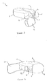
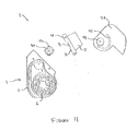
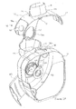
- an inhaler 1 according to a first embodiment of the invention comprising a housing 2 to which is pivotally mounted an actuator 3.
- a cap 4 is integrally hinged to the top edge of the housing 2 and is pivotable between a closed position, as shown in Figure 1 , to an open position, as shown in Figure 2 , to gain access to a mouthpiece 5 integrally formed with and upstanding from the actuator 3.
- the cap 4 completely covers and protects the mouthpiece 5 when closed and prevents contamination thereof or the possible ingress of dirt into the housing 2 which could otherwise be inhaled when the device is used.
- the inhaler 1 is intended for use with a strip 6 of moisture proof blisters (see Figure 13 ) each containing a pre-measured dose of powdered medicament for inhalation.
- Each blister 6a in the strip 6 comprises a generally hemispherically shaped pocket 6b and a flat puncturable lid 6c permanently heat sealed to the pocket 6b to hermetically seal the dose therein.
- the strip 6 is preferably manufactured from foil laminate or a combination of foil laminate, such as aluminium, and plastics material.
- the blisters consist of a base and a lid.
- the base material is a laminate comprising a polymer layer in contact with the drug, a soft tempered aluminium layer and an external polymer layer.
- the aluminium provides the moisture and oxygen barrier, whilst the polymer provides a relatively inert layer in contact with the drug.
- Soft tempered aluminium is ductile so that it can be "cold formed” into a blister shape. It is typically 45 ⁇ m thick.
- the outer polymer layer provides additional toughness to the laminate.
- the lid material is a piercable laminate comprising a heat seal lacquer, a hard rolled aluminium layer (typically 20-30 ⁇ m thick) and an external lacquer layer.
- the heat seal lacquer bonds to the polymer layer of the base foil laminate during heat sealing.
- Materials for the polymer layer in contact with the drug include poly vinyl chloride (PVC), polypropylene (PP) and polyethylene (PE).
- PVC poly vinyl chloride
- PP polypropylene
- PE polyethylene
- the heat seal lacquer on the foil lid is replaced with a further layer of PE.
- the two layers of PE melt and weld to each other.
- the external polymer layer on the base foil is typically oriented polyamide (oPA).
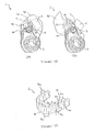
- the actuator 3 comprises a lever arm 7 having one end pivotally mounted to the housing 2 to enable it to rotate from a closed position shown in Figures 1, 2 and 4 into an open position shown in Figure 3 .
- the housing 2 has an aperture 8 therein to receive a piercing member comprising a pair of piercing heads 9 that extend from the lever arm 7 when the actuator 3 is in a closed position and penetrate the lid 6c of a blister located within the housing 2 immediately behind the aperture 8.
- Each piercing head 9 comprises a generally "H" shaped element having a flat blade-like central tooth or primary cutting element 10 and a pair of flat blade-like end teeth or secondary cutting elements 11 extending laterally across each end of the primary piercing element 10.
- Each of the primary and secondary cutting elements 10,11 taper to a pointed tip.
- the pointed tip 10a of the primary cutting element 10 may be located in its centre i.e. midway between the secondary cutting elements 11. However, it may be advantageous to form the primary cutting element 10 so that its pointed tip 10a is closer to one of the secondary piercing elements 11 than the other secondary cutting element 11, for example in order to facilitate correct piercing when the angle of approach of the piercing heads 9 is not normal to the foil.
- the height of each of the secondary cutting elements 11 is such that the pointed tips 11a of the secondary cutting elements 11 are at the same height as the edges of the primary cutting element 10 where the primary and secondary cutting elements 10,11 meet each other.
- the pointed tip 10a of the primary cutting element 10a is therefore above the pointed tip 11a of each of the secondary cutting elements 11 so that the primary cutting element 10 slits, or has at least initiated, the first linear slit in the blister before either of the secondary cutting elements 11 begin to cut the second linear slits in the blister.
- the top edges of each primary and secondary cutting elements10,11 are sharpened to enable them to easily penetrate and cut the lid 6c of a blister 6a.
- the secondary cutting elements 11 of each piercing head 9 upstand from opposite edges of an aperture 12 in the lever arm 7 to enable the flow of air through the arm 7 into and out of the blister 6b via the holes made in the lid 6c of the blister 6b with the piercing members 9.
- the primary cutting element 10 is attached to, and is supported between, each of the secondary cutting elements 11 and the primary cutting element extends across the aperture 12 and so is not attached directly to the lever arm 7.
- Figure 8B illustrates a short section of a strip 6 of blisters 6a to show the shape and size of the openings that each of the piercing elements 9 described with reference to Figure 8A cut in the lid 6c of a blister 6b.
- the primary cutting elements 10 penetrate the lid 6c first (point A in Figure 8B ) and, as they enter the blister 6a, two linear cuts or slits are made by each of them, as indicated by arrows "B".
- the secondary cutting elements 11 penetrate the blister 6a and further linear cuts are made at each end of the linear cuts perpendicular to the first linear cut formed by the primary piercing element 10, as indicated by arrows "C".
- These cuts have the effect of creating flaps 12a that are folded back into the blister 6a as the piercing head 9 enters further into the blister.
- These piercing heads 9 are capable of forming openings that extend to over 30 to 50% of the surface area of a lid 6c of a blister 6a.
- the blister lid area is 67mm 2 and the piercers open an area of 29mm 2 which is equivalent to 43% of the surface area of the lid.
- a cover 13 is pivotally attached to the side of the housing 2 and encloses a space to receive used blisters 6d that are fed into said space through a slot 14 in the wall of the housing 2.
- the space within the cover 13 is large enough to accommodate only a few used blisters 6d therein and so a resiliently flexible blister grip 15 extends from the housing 2 and facilitates removal of some of the used blisters 6d from the blisters 6 that remain in the housing 2.
- the blister grip 15 is pressed against the strip 6 to sandwich it between the blister grip 15 and the sidewall of the housing 2.
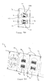
- FIGS 10A to 10C show three front cross-sectional views through the inhaler 1.
- Figure 10A there are no empty blisters 6d protruding through the slot 14.
- Figure 10B the device has been activated twice more and so two empty blisters 6d have now passed through the slot 14.
- Figure 10C the blister grip 15 has been pressed against the housing 2 in the direction of arrow "A" to enable the two empty blisters 6d to be detached by pulling them in the direction of arrow "B".
- a cover 13 is not essential and the used blisters 6d may be removed as soon as they emerge from the aperture 14 in the wall of the housing 2.
- the inhaler 1 may be provided with a cutting implement (not shown) such as a blade or serrations against which the section of used blisters 6d to be removed may be pressed to facilitate their detachment.
- a blade may be mounted to and extend from the blister grip 15 so that when it is pressed against the housing 2 it cuts the strip 6d located between the blister grip 15 and the housing 2.
- the inhaler 1 may incorporate a larger chamber possibly with a take-up spool around which the used blister strip 6d may be wound so that it can be removed as a whole from the device and so avoid the need to detach sections of the strip 6d as each short section of blisters 6a are used up.
- a take-up spool around which the used blister strip 6d may be wound so that it can be removed as a whole from the device and so avoid the need to detach sections of the strip 6d as each short section of blisters 6a are used up.
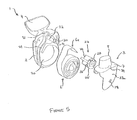
- the housing 2 comprises a generally cylindrically shaped chamber 20 to receive a coiled or wound strip of blisters 6 each containing a pre-measured dose of medicament to be delivered using the inhaler 1.
- the leading end 6e of the strip 6 is received in a blister feed inlet path 21 which opens up into a generally cylindrical cavity 22 adjacent to and in communication with the aperture 8 in the housing 2 and in which is rotatably received an indexing wheel 23.
- a used blister feed outlet path 30 extends from the cylindrical cavity 22 and leads to the aperture 14 in the wall of the housing 2.
- the chamber 20 has a cover (not shown in Figure 5 ) that forms part of the housing 2.
- the cover is removably attached to the remainder of the housing 2 to enable access to the inside of the inhaler 1 to be obtained to enable a fresh strip 6 of blisters to be inserted therein.
- the device could form a disposable unit in which case a strip of blisters 6 could be mounted in the device during assembly and the cover permanently attached so that once the strip has been exhausted, the whole device is thrown away.
- the simplicity of the construction of the device and the relatively few separate components make the device very cheap to manufacture and so a disposable unit is a viable proposition.
- the indexing wheel 23 is a generally cylindrically shaped member with a set of blister receiving grooves or recesses 24 extending longitudinally along its outer surface parallel to its axis of rotation. Each groove 24 is shaped so as to receive a blister 6a therein as the indexing wheel 23 rotates, as will be explained in more detail below.
- the recesses 24 are spaced at a pitch which is equal to the distance "d" between the centre lines of a pair of blisters, as indicated in Figure 13 , so that as the indexing wheel 23 rotates, a strip 6 extending through the blister feed path 21 and over the indexing wheel 23 is pulled so that a blister 6a locates in the recess 24 of the indexing wheel 23 situated immediately opposite the aperture 8, as will be explained in more detail below.
- ratchet teeth 25 are formed on one end face thereof for cooperation with the actuator 3 as will shortly be explained, each tooth 25 comprising an arcuately shaped ramp section 26 and a shoulder 27.
- the indexing wheel 23 is a close fit in the cylindrical cavity 22 so that the strip 6 is securely held by the indexing wheel 23 and each blister 6a is snugly received and held in the recess 24 opposite the aperture 8 whilst allowing for rotation of the indexing wheel 16 to feed the strip of blisters 6 through the device.
- the used blisters 6d are fed out of the cavity 22 down the used blister feed path 30 and through the slot 14 out of the housing 2.
- a drive plate 27a depends from a longitudinal edge of the lever arm 7 and carries a drive pawl 28 thereon for cooperation with the ratchet teeth 25 on the indexing wheel 23 during rotation of the actuator 3 from the open to the closed position.
- the drive pawl 28 is integrally formed in the drive plate 27a by cutting a U-shaped slot therein to form a resiliently deformable tab 29 from which the drive pawl 28 upstands.
- the mouthpiece 5 is integrally formed with the lever arm 7 of the actuator 3 and upstands from one side thereof opposite to the side from which the piercing heads 9 extend.
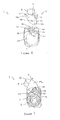
- the interior of the mouthpiece 5 can be seen from the cross-sectional view of Figure 9 and is divided into a primary and a secondary chamber 31,32 by a partitioning wall 33.
- An outside air inlet orifice 34 in the sidewall of the mouthpiece 5 close to where it joins or becomes the lever arm 7 is in communication with the primary chamber 31.
- the primary chamber 31 is also in communication with one of the apertures 31a in the lever arm 7 that is formed in the vicinity of a piercing head 9.
- the secondary chamber 32 makes up the main internal volume of the mouthpiece 5 and is in communication with the other aperture 11b in the lever arm 7.
- a bypass aperture 35 extends through the partitioning wall 33 to communicate the primary chamber 31 with the secondary chamber 32 for reasons that will become apparent.
- the housing 2 is provided with an integrally formed resiliently flexible arm 36 carrying an anti-rotation pawl 37 that normally locates in one of the recesses of the indexing wheel 23 which is not occupied by a blister 6a, as shown in Figure 6 .
- a release pin 38 upstands from the drive plate 27a which engages the arm 37 to push the pawl 37 out of the recess to allow rotation of the indexing wheel 23 when the actuator 3 approaches its fully open position.
- a second resiliently deformable anti-rotation pawl 39 is provided on the housing 2.
- the second anti-rotation pawl 39 has a cam surface 40 thereon which is engaged by a cam member 41 on the actuator 3 when the first anti-rotation pawl 37 is pushed out of the recess 24 of the indexing wheel 23.
- the second anti-rotation pawl 39 is therefore locked into position and protrudes into another recess 24 of the indexing wheel 23. This prevents the indexing wheel 23 from rotating by more than approximately 45 degrees and so the strip 6 can only be pulled through the device by about half a blister width.
- the inhalation device has a very simple construction with relatively few components. If the cap 4 is integrally formed with the housing 2 in a single moulding and the actuator 3 is formed together with the mouthpiece 5, the piercing heads 9, the drive plate 27a and the drive pawl 28 in another moulding, the device can be formed from as few as 4, 5 or 6 moulded plastic parts.
- the cap 4 and the lever arm 7 are both in a closed position in which the cap 4 covers the mouthpiece 5 and the lever arm 7 lies generally against the side of the housing 2 with the piercing heads 9 extending through the aperture 8 in the housing 2 and into a previously exhausted blister 6d lying immediately below the aperture 8 and constrained in the uppermost recess 24 of the indexing wheel 23 adjacent to the aperture 8.
- the first and second anti-rotation pawls 37,39 prevent rotation of the indexing wheel 23 in either direction and so locate the blister in position.
- the lever arm 7 When the cap 4 is opened, the lever arm 7 can be pivoted into the position shown in Figure 3 . As the lever arm 7 pivots, the drive pawl 28 on the drive plate 27a rides up the ramp section 26 forming one of the ratchet teeth on the end of the indexing wheel 23 and so no rotation of the indexing wheel 23 occurs. Once a fully open position has been reached, as shown in Figure 3 , the drive pawl 28 has reached the end of the ramp section 26 and drops down against the face of a corresponding shoulder 27 so that as the actuator 3 is rotated back in the opposite direction from the open to the closed position, engagement between the drive pawl 28 and the shoulder 27 causes the indexing wheel 23 to rotate. It will be appreciated that if the lever arm 7 is not opened to its fullest extent before being returned to its closed position, the indexing wheel 23 will not rotate because the drive pawl 28 will not have dropped down to engage a shoulder 27 at the top of the ramp section 26.
- the release pin 38 on the drive plate 27a engages with the arm 36 from which the first anti-rotation pawl 37 extends and deflects it so that the anti-rotation pawl 37 moves out of the recess 24 in the indexing wheel 23 so that the indexing wheel 23 can rotate and the strip 6 can be indexed when the lever arm 7 is rotated in the opposite direction.
- the cam member 41 engages with the cam surface 40 of the second anti-rotation pawl 39 and locks it into position to ensure that the strip 6 cannot be pulled from the inhaler 1 by more than approximately half the width of a blister 6b.
- the indexing wheel 23 is rotated through 90 degrees as a result of engagement between the drive pawl 28 and the shoulder 27 on the indexing wheel 23. Whilst the lever arm 7 is rotated back into its closed position, the anti-rotation pawls 37,39 have returned to their original positions locking the indexing wheel 23 in place. This rotation of the indexing wheel 23 brings the next blister 6b into position immediately below the aperture 8 in the housing 2.
- the piercing heads 9 pass through the aperture 8 in the housing 2 and penetrate the lid 6c of the blister 6a that has just been moved into position by the indexing wheel 23.
- the dose is now ready for inhalation, as will now be described.
- the turbulent airflow generated through the aperture 31b in the lever arm 7 around the piercing element 9 helps to deagglomerate the dose and create a respirable aerosol.
- the air bypass orifice 35 in the partitioning wall 33 between the primary and secondary chambers 31,32 reduces the overall pressure drop across the device and so makes it easier for the patient to inhale. It also increases turbulence in the secondary chamber 32.
- the bypass orifice 35 is situated so that the airflow therethrough, indicated by arrow "Y" in Figure 9 , meets the airflow entering the secondary chamber 32 from the blister at a tangent or right angle so as to create a cyclonic effect or increase the airflow turbulence to assist deagglomeration.
- the side cover 13 may be opened and the visible section 6d of used blisters may be detached from those that remain within the device as has already been explained.
- the actuator is coupled to the cap covering the mouthpiece so that a blister is pierced when the cap is opened and indexed to move the next unused blister into position beneath the aperture in the housing when the cap is closed.
- the inhaler 1 is similar to the device described with reference to the first embodiment except that the ratchet teeth on the indexing wheel 23 have been replaced with a toothed gearwheel 40a which is attached to the indexing wheel via a one-way or clutch mechanism (not shown) so that the indexing wheel 23 will rotate together with the gearwheel 40a in only one direction of rotation, the gearwheel being free to rotate in the opposite direction relative to the indexing wheel 23.
- the actuator has a similar construction to the actuator 3 of the first embodiment and comprises a lever arm 7 with the mouthpiece 5 and piercing heads 9 upstanding from opposite sides thereof.
- a cam pin 41a protrudes from the side of the lever arm 7 adjacent to the remote end opposite the end pivotally mounted to the housing 2.
- the cam pin 41 is located in a cam track or groove 42 formed on the inside surface of a cap 43 pivotally attached to the side of the housing 2 at the same end but spaced from the location at which the actuator 3 is pivotally attached to the housing 2.
- the cap 43 also carries a toothed gearwheel 44 attached thereto for rotation together with the cap 43, which lies in meshing engagement with the gearwheel 40a on the indexing wheel 23.
- the inhalation device according to the second embodiment also has a very simple construction with relatively few components.
- the gearwheel 44 is integrally formed together with the cap and the actuator 3 is formed together with the mouthpiece 5 and the piercing heads 9, the whole device can be formed from as few as 4, 5 or 6 moulded plastic parts.
- the devices of the present invention will have a capacity to hold between 1 and more than 100 doses although preferably it will be capable of holding between 1 and 60 doses and most preferably between 30 and 60 doses.
- the payload of each blister may be between 1 ⁇ g and 100mg. However, preferably, the payload is in the region of 1mg to 50mg and most preferably between 10mg and 20mg.
- the device may be disposable once all the blisters contained therein have been used up. In this case, the housing may be formed as a permanently sealed enclosure to prevent tampering.
- FIG. 12A when the cap 43 is closed, the piercing heads 9 on the actuator 3 are held clear from the aperture 8 in the housing 2 by means of the cam pin 41a located in the cam track 42 in the cap 43.
- the cam track 42 is preferably shaped so that the cap 43 can be initially pivoted relative to the housing 2 by at least 90 degrees without any movement of the actuator 3 occurring thereby allowing inspection or cleaning of the mouthpiece 5 without piercing of a blister 6a.
- the cam pin 41a is guided by the track 42 causing the actuator 3 to pivot into a position shown in Figure 12B in which the piercing elements 9 extend through the aperture 8 in the housing 2 and penetrate a blister 6b situated immediately behind the aperture 8 within the housing 2.
- the dose may be inhaled through the mouthpiece 5.
- the indexing wheel 23 does not rotate as the cap 43 is opened and the gearwheel 40a is rotated in this first direction.
- drive of the gearwheel 40a is transferred to the indexing wheel 23 so that it rotates and moves the next blister 6a into alignment with the aperture 8.
- an opening or window could be provided in the housing 2 and a dose number printed on each blister 6a readable through the opening or window so that the user can monitor the number of doses that have been used or that remain in the device. This avoids the need for a complicated dose counting mechanism often found in conventional devices.
- the housing 2 could be wholly or partially formed from a transparent material so that the number of blisters 6 remaining in the device can clearly be seen through the walls of the housing 2.
- the blister strip 6 provided for use with the inhaler 1 of the invention may be provided with serrations, cut-lines 50 or other frangible features to facilitate the separation of the blisters 6a from each other.
- the edge of the blister strip 6 may be provided with notches 51 between each blister 6a to make the strip easier to tear.
- This version of the device has the particular benefit of being small in size relative to the number of blisters that it may contain.
- the indexing wheel is formed integrally with the hinge, which pivotally connects the actuating lever to the housing. This frees up more space within the housing for blister storage.
- the device is able to contain a coil of at least 60 blisters.
- the inhaler 50a is similar to the inhaler 1 of the first embodiment and comprises a housing 51a having an actuator 52 in the form of a lever arm 53 pivotally mounted to the housing 51a at one end.
- a piercing member comprises a pair of piercing heads 54 that extend from the lever arm 53 and locate in an aperture 55 in the housing when the actuator 52 is in a closed position with the lever arm 53 lying substantially against the housing 51a, as shown in Figure 14A .
- a cap 56 is pivotally attached to the housing 51a and is operable to cover the mouthpiece 57 when the inhaler is not in use.
- the mouthpiece 57 is integral with the lever arm 53 although it has a triangular or semicircular section against which the lips can be placed, as opposed to a tubular section which is placed in the mouth.
- the shape of the mouthpiece and the airway construction within it is illustrated in the cross-sectional view of Figure 17 . It will be appreciated that the airway construction is very similar to the construction of the airway described with reference to the first and second embodiments and so no further description of it will be made here. However, it will be appreciated that because the indexing wheel is now located away from the region where the blister is pierced, the blister to be pierced is now supported in a blister support block 58 (see Figure 17 ).
- the device 50a includes an indexing wheel (not shown) incorporating a ratchet mechanism as has already been described with reference to the first and second embodiments, except that in this embodiment the indexing wheel has been made integral with the hinge about which the lever arm 53 pivots so that it rotates about the same axis as the lever arm 53.
- the device may incorporate a chamber to receive used blisters.
- a cutting edge 59 may extend from the aperture against which used blisters may be torn off by pulling them against the edge in the direction indicated by the arrow in the drawing.
- the cutting edge may be serrated to facilitate detachment. It will be noted that the strip is prevented from being pulled out of the device by the piercing heads, which are located in a blister, and secures it in position.
- piercing member may be used including solid or hollow pins as well as piercing blades.
- piercing head 60 which may be employed with any embodiment of the invention and which allows a freer flow of air into the blister will now be described with reference to Figures 18 and 19 .
- the piercing member 60 is preferably integral with the lever arm that has a pair of apertures 61 therein for the flow of air into the blister and the flow of air together with the dose out of the blister.
- the piercing member 60 comprises a pair of piercing heads each of which comprises a pair of secondary cutting elements 62 spaced from each other and extending in a lateral direction from a pointed primary cutting element 63 which is mounted on and extends between the secondary cutting elements 62.
- the primary and secondary cutting elements 63,62 extend over one of the apertures 61 in the lever arm 53..
- Each of the secondary cutting elements 62 divided into first and second cutting members 62a, 62b that extend laterally from opposite sides of the primary cutting element 63.
- the first and second cutting members 62a, 62b are upwardly angled away from the lever arm and the primary cutting element upstands from the secondary cutting member 62 at the point where the first and second cutting members 62a,62b of each secondary cutting element 62 meet.
- the secondary cutting elements 62 incline inwardly toward each other so that the central piercing member 63 has diamond shape in side profile. As shown in Figure 19B , this open construction allows more air to flow around the sides of the blister in comparison with the piercing member arrangement of Figure 8A , as the side teeth restrict airflow into the blister (as shown in Figure 19A ).
- piercer of the present invention can be chosen to suit different sizes and shapes of blisters.
- number and arrangement of piercers can be varied within the scope of the invention.
- a large blister may have a pair of larger piercers, or multiple pairs of smaller piercers, for example two piercers for the air inlet and two for the air outlet.
- the use of the piercer of this invention is not limited to the inhalers described in the embodiments and may be used with any inhaler comprising a puncturable blister.
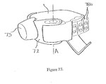
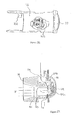
- the inhaler 70 comprises a housing 71 having an actuator 72 pivotally mounted thereto for rotation relative to the housing 71 about an axis indicated by the line marked "A" in Figures 20 to 22 .
- a cap 73 is pivotally attached to the housing 71 and may be moved between an open position, as shown in Figure 20 , and a closed position in which the cap 73 covers a mouthpiece 74 to protect it and to prevent the ingress of dirt into the housing 71 through the mouthpiece 74.
- the actuator 72 has been pivoted about axis "A" from its closed position shown in Figure 20 into its fully open position to reveal a piercing member, comprising a pair of piercing heads 75, upstanding from the actuator 72 and an aperture 76 in the housing 71 through which the piercing heads 75 extends when the actuator 72 is in its closed position.
- a finger grip 77 is integrally moulded into the front lip of the actuator 72 to facilitate movement of the actuator 72 by the user between its open and closed positions.
- the housing 71 contains a coiled strip of blisters 78 (see Figure 23 ) and one such blister 78a (see figure 21 ) is located in a piercing position in which it is visible through the aperture 76. It will be noted that each of the blisters in the strip 78 are numbered and the number of the blister located in a piercing position is also visible through the aperture 76. One edge of the aperture 76 is provided with a cutout 79 (see Figure 21 ) to enable the number of this blister 78a to be seen by the user when the actuator 72 is in its open position.
- a cover 80 is pivotally attached to the housing 71 and encloses a space to receive used blisters 78b that are fed into this space through a slot 81 (see Figure 24 ) formed in the wall of the housing 71. It will be appreciated that the space enclosed by the cover 80 is sufficiently large enough to accommodate only a few used blisters 78b at a time and so a section of used blisters 78b must periodically be removed from those unused blisters 78 that remain in the housing 71.
- the cover 80 is pivotally hinged to the housing 71 for rotation about an axis which is substantially parallel to the direction of movement of used blisters 78b out of the housing 71.
- the housing 71 is preferably formed in two halves which, as with all the embodiments, may be formed from a translucent plastic such as polypropylene and which are held together using suitably positioned and integrally moulded clip-in mounting pins (not shown) that cooperate with corresponding mounting posts 83.
- a translucent plastic such as polypropylene
- clip-in mounting pins not shown
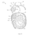
- FIG. 23 In the side view of the device shown in Figure 23 , one half of the housing 71 has been removed so that the location and path of a coiled strip of blisters 78 through the housing 71 is clearly visible, as are the internal components of the device.
- the mouthpiece cap 73 and the cover 80 have been omitted from Figure 23 for the purposes of clarity.
- the two casing halves may be separable by the user to enable them to refill the housing with a fresh strip of blisters
- the inhaler could be of the "single use" type in which a strip of blisters is located in the housing during assembly, which is then subsequently sealed. Once that strip of blisters has been exhausted, the whole device is simply thrown away.
- the simplicity of the preferred embodiments of the device and the fact that they are made from a relatively small number of components (no more than nine), all of which are made from a plastics material means that it is very cheap to manufacture and so rendering it disposable after a single strip of blisters has been exhausted is a viable proposition. Sealing the housing during manufacture also renders the device tamperproof.
- the blister strip 78 passes over a blister strip locator chassis 84 received in the housing 71 and mounted adjacent to the aperture 76.
- the chassis 84 comprises two arcuately shaped parallel wall members 84a, 84b joined to and spaced from each other by a width which is only slightly greater than the width of the blister strip 78 so that the strip 78 (only a short section of which is shown in Figure 25 ) passes between the wall members 84a, 84b and is guided and supported by them and by the upper wall of the housing 71 as the strip 78 passes therethrough.
- Each wall member 84a, 84b is provided with integrally moulded lugs 85 that locate between corresponding lugs 86 integrally moulded into the housing 71.
- each wall member 84a, 84b has slots 87 which mate with corresponding locating features 85 on the housing 71 to firmly mount the strip locator chassis 84 in position.
- the strip locator chassis 84 includes a resiliently deformable arm 88 depending from between the wall members 84a, 84b.
- the arm 88 is preferably integrally moulded together with the strip locator chassis 84 from a plastic material such as acetal.
- the free end of the arm 88 is divided into two forks 89 between which an indexing wheel 90 is rotatably mounted.
- the indexing wheel 90 has four spokes 91 arranged in an "X" shape and it is positioned substantially coaxial with the axis "A" about which the actuator 72 rotates with respect to the housing 71.
- the housing 71 is also provided with indexing wheel anti-rotation and location ramps 92,93 which the indexing wheel 90 interacts with to selectively prevent and permit rotation of the indexing wheel 90, as will be explained in more detail later.
- the actuator 72 includes a pair of flanges 94a,94b (see Figures 24 and 25 ).
- One flange 94a has a shaped opening 95 that locates directly on a correspondingly shaped spigot 96 integrally formed on one-half of the housing 71.
- the other flange 94b is provided with a larger opening 97 that is shaped to receive a coupling plate 98 therein.
- the flange 94b is provided with a recess 99 in the edge of the opening 97 in which is received a locating tab 100 protruding from the coupling plate 98.
- the coupling plate 98 has a shaped opening 98a that locates on a correspondingly shaped spigot 101 on the other half of the housing 71.
- An arcuately shaped opening 104 in the housing 71 surrounds the spigot 101 through which extends an angularly shaped drive tooth 102, which protrudes inwardly from the coupling plate 98.
- the drive tooth 102 extends into a space between two spokes 91 of the indexing wheel 90 and its function will now be described with reference to Figure 26 .
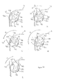
- Figure 26 illustrates a series of drawings to show how the indexing mechanism works when the actuator 72 is rotated between its closed and open position and back to its closed position once again.
- the blister strip 78 has been omitted from Figure 26 for clarity although it will be apparent that, as the indexing wheel 90 rotates, a blister will be located between a pair of spokes 91 and pulled through the housing 71.
- the actuator 72 is in its closed position and the arm 88, with the indexing wheel mounted thereto, lies in an unstressed or relaxed state in which no external forces are applied to it.
- the drive tooth 102 can be seen positioned between two of the spokes 91a, 91b and spoke 91d is positioned between the anti-rotation and location ramps 92,93.
- the anti-rotation ramp 92 prevents any rotation of the indexing wheel 90 in a clockwise direction as viewed in the drawing.
- the actuator 72 is now rotated back into its closed position, in the direction of arrow "C" in Figure 26E .
- the drive tooth 102 is shaped so that, on the return stroke of the actuator 72, it slides over the top of the preceding spoke 91a and does not rotate the indexing wheel 90 in a clockwise direction.
- engagement of the drive tooth 102 with the indexing wheel 90 actually causes the arm 88 and the indexing wheel 90 to deflect downwardly in the direction of arrow marked "D" in Figure 26E .
- spoke 91c is pushed down in between the anti-rotation and location ramps 92,93 thereby preventing any rotation of the indexing wheel 90 in either direction.
- the piercing heads 75 pierce a previously unused blister that has just been indexed into place and is visible through the aperture 76 in the housing 71.
- the piercing heads 75 may be integrally formed together with the actuator 72, it is also envisaged that the piercing member may be formed as a separately moulded component 105, as shown in Figures 27 , 27A and 27B , which locates in a walled recess 103 in the actuator 72, as shown in Figure 28 . The piercing heads then extend from this separately moulded component. This will now be described in more detail.
- the piercing member 105 may be used with any of the embodiments of the inhalation device described herein and, as shown in Figure 27 , 27A and 27B , comprises a main body portion 106 having an upper surface 107 which lies flush against the upper surface of a lid of a pierced blister 119 when the piercer has fully entered the blister 119.
- the piercing heads comprise one piercing tooth 108 upstanding from the upper surface 107 and another piercing tooth 109 upstanding from a relieved or recessed region 107a of the upper surface 107.
- the geometry of teeth 108,109 is similar to the geometry of the teeth already described with reference to Figures 18 and 19 .
- Apertures 110,111 are formed in the upper surface 107 and recessed region 107a beneath teeth 108,109 respectively.
- angles of the piercer are chosen to facilitate effective and clean cutting of the foil without tearing the foil in an uncontrolled manner.
- the preferred ranges and values for these angles are given in the table below: Angle Preferred range Value of embodiment of Figures 27 , 27A, 27B a 15° - 45° 33° b 15° - 45° 34° c 5° - 30° 15° d 5° - 30° 16°
- each secondary cutting element 62 may be formed so that it is positioned asymmetrically with respect to the secondary cutting elements 62.
- the first and second cutting members 62a,62b of each secondary cutting element 62 each extend laterally from the primary piercing element by different distances such that the two flaps formed by a piercing head are not the same size, as can be seen in Figure 27A .
- the piercing heads 108,109 are arranged so that smaller flaps are formed towards the ends of the blister's major axis where the depth of the blister is shallower, and longer flaps are formed towards the centre of the blister where the blister is deeper.
- the relative length of the first and second cutting members 62a,62b is defined by the ratio k:j in Figure 27A .
- this ratio is between 1 and 2.
- the ratio is 1.2.
- a short tubular section 112 depends from the other side of the main body portion 106 in the opposite direction to the tooth 108 and is in communication with the aperture 110.
- the outer surface of the tubular section 112 has axially extending spacer ridges 113 for reasons that will become apparent.
- a mounting pin 114 also depends from the main body portion 106 to facilitate attachment of the piercing member105 to the actuator 72.
- Tooth 109 upstands from a recessed region of the main body portion 106 so that a gap is created between the blister lid 119a and the surface of the recessed region 107a to allow free and unrestricted flow of air into the blister 119 through the aperture 109.
- the drug 119c contained in the blister 119 is entrained in the airflow entering the blister 119 formed by tooth 109 and is carried out of the blister 119 through the opening cut by tooth 108 through the aperture 110 and tubular section 112 into the mouthpiece 74 from where it passes into the patient's airway.
- the upper surface 107, around tooth 108 is shaped to fit closely against the blister lid when the teeth 108,109 have entered the blister 119 to their fullest extent so that leakage of air into the exit airflow between the upper surface 107 and the blister lid 119a is minimised.
- bypass conduit 118 to reduce the overall pressure drop across the device and make it easier for the patient to inhale a dose, outside air is introduced into the exit airflow through a bypass conduit 118.
- the piercing head 105 is mounted to the actuator 72 via the tubular section 112 that locates within the walled recess 103.
- the ridges 113 form an interference fit with the walled recess 103 but gaps or spaces between the ridges 113 form a bypass conduit 118 through which bypass air is drawn into the mouthpiece 74 together with the airflow passing through the blister 119. It will be appreciated that the bypass air does not pass through the blister 119 but enters the mouthpiece 74 separately.
- a mesh 115 may also be moulded into the mouthpiece 74 through which all the inspired air passes so as to provide additional dispersion.
- Holes 116 are provided in a region where the mouthpiece 74 joins the actuator 72 through which air is fed via the aperture 111 into the blister 119 and, via the bypass conduit 118 formed by the spaces between ridges 113, into the mouthpiece 74.
- FIG. 29 The airflow through a pierced blister 119 and into the mouthpiece 74 is illustrated schematically in Figure 29 .
- air is drawn from outside through the holes 116 between the mouthpiece 74 and the actuator 72 from where it flows into the blister 119 through the aperture 111, as indicated by arrow marked "F".
- air is also drawn into the blister 119 through the space between the lid 119a of the blister 119 and the recessed surface 107a, as indicated by arrow marked "G”.
- This embodiment as described has nine moulded components. While this is significantly fewer than other devices with a similar number of doses it is possible to reduce the component count still further.
- the case halves can, for example, be moulded as a single moulding connected by a moulded-in hinge at the base of the components. In assembly the two halves would be folded together to form the housing. Similarly, the cap and blister door can be integrally moulded.
- the piercing element can be moulded as part of the actuator. In this way the number of moulded components can be reduced to five or six.
- a take-up spool is required onto which the used blister strip is wound.
- the obvious disadvantage of a take-up spool is that at all times during use of the device there is an empty space within it. When the device is first used, the take-up spool is empty, and at the end of its life, the feed spool is empty. Accordingly, the device must be made larger to accommodate the blister strip both before and after use.
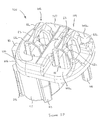
- the inhalation device retains used blisters in a more compact arrangement in which there is no unused space. This is achieved by forming the blister strip into an endless loop and mounting the loop in the housing in a state in which it has been wrapped around itself, as shown in Figure 30 .
- the housing 120 contains two spaced parallel walls 121, 122to define a pair of parallel spiral channels 123,124 therebetween.
- the inner end of the channels 123,124 open out into a central chamber region 125 in which is rotatably mounted a feed spool 126 and a feed sprocket 127.
- the blister strip 130 passes from one channel 123 to the other channel 124 through the chamber region 125 and extends around the feed spool 126 and the feed sprocket 127 in an "S" shaped configuration.
- the blister strip 130 also passes out of one channel 124 and is wrapped around an indexing wheel (shown generally by reference numeral 128 in Figure 30 ) before passing back into the other channel 123.
- the connections at both ends in effect create a single endless channel for the blister strip 130.
- the blister strip 130 may be conventionally formed before its ends are subsequently joined together. If the length of the strip 130 matches the combined length of the two channels 123,124, the strip 130 can be loaded into the channels 123,124 and located around the teeth (not shown) of the indexing wheel 128 and the inner sprocket 127, as well as being guided around the spool 126.
- the indexing wheel 128 indexes the strip 130 via a mouthpiece/actuator arrangement, as has already been described above with reference to Figures 20 to 26 , although other indexing mechanisms may also be used.
- the inner spool 126 and sprocket 127 need not be driven other than by the strip 130 itself.
- the spool 126 and sprocket 127 may be connected to the indexing wheel 128 by a simple drive train, belt or similar mechanism (not shown).
- the strip 130 is endless, with regularly spaced blisters, then the user will be able to index the strip 130 indefinitely. Including a blank section 129 in the strip 130 that has no blisters can provide a clear indication that all blisters have been used. This could conveniently be provided at the point where the ends of the strip 130 are joined together. When this blank section 129 of the strip reaches the indexing wheel 128, the strip 78 will no longer be indexed as the indexing wheel 128 rotates, clearly indicating that the strip 130 has been exhausted. In the drawing, the strip 130 is shown with the blank section 129 located just after the indexing wheel 128. This is the position it will be in before the device has been used for the first time.
Abstract
Description
- The present invention relates to an inhalation device for oral or nasal delivery of medicament in powdered form. The invention also relates to an inhaler containing a strip of blisters each having a puncturable lid and containing a dose of medicament for inhalation by a user of the device according to the invention and, to a method of using such a device.
- Oral or nasal delivery of a medicament using an inhalation device is a particularly attractive method of drug administration as these devices are relatively easy for a patient to use discreetly and in public. As well as delivering medicament to treat local diseases of the airway and other respiratory problems, they have more recently also been used to deliver drugs to the bloodstream via the lungs thereby avoiding the need for hypodermic injections.
- In one type of conventional metered dose inhalation device, the powdered medicament is held in a reservoir within a dispensing device that is operable to measure out and dispense a predetermined amount of powder for each dose. However, these devices suffer from poor dose metering capability especially when the size of the dose is relatively small as it is difficult to accurately measure out small amounts of dry powder in such a device. It is also difficult to protect the drug from the ingress of moisture and to seal it from the atmosphere until it is required for administration to a patient.
- It is common for dry powder formulations to be pre-packaged in individual doses, usually in the form of capsules or blisters which each contain a single dose of the powder which has been accurately and consistently measured. A blister is generally cold formed from a ductile foil laminate or a plastics material and includes a puncturable lid which is permanently heat-sealed around the periphery of the blister during manufacture and after introduction of the dose into the blister. A foil blister is preferred over capsules as each dose is protected from the ingress of water and penetration of gases such as oxygen in addition to being shielded from light and UV radiation all of which can have a detrimental effect on the delivery characteristics of the inhaler if a dose becomes exposed to them. Therefore, a blister offers excellent environmental protection to each individual drug dose.
- Inhalation devices that receive a blister pack comprising a number of blisters each of which contain a pre-metered and individually packaged dose of the drug to be delivered are known. Actuation of the device causes a mechanism to open a blister so that when the patient inhales, air is drawn through the blister entraining the dose therein that is then carried out of the blister through the device and via the patient's airway down into the lungs.
- It is advantageous for the inhaler to be capable of holding a number of doses to enable it to be used repeatedly over a period of time without the requirement to open and/or insert a blister into the device each time it is used. Therefore, many conventional devices include means for storing a number of blisters each containing an individual dose of medicament. When a dose is to be inhaled, an indexing mechanism moves a previously emptied blister away from the opening mechanism so that a fresh one is moved into a position ready to be opened for inhalation of its contents.
- A problem with conventional inhalation devices is that they are relatively large, heavy and difficult to operate. Despite their large size, many of them only have sufficient capacity to hold a relatively small number of doses before the device must be opened and a fresh set of blisters mounted therein. Although it may be possible to increase the number of blisters by making them smaller, this can only be achieved at the expense of reducing the dose payload or capacity of each blister. This is particularly disadvantageous when the device is to be used to deliver for example newer, less potent drugs where each blister must be able to hold a payload of somewhere in the region of 10-20mg of the drug.
- Due to their nature and method of operation, conventional inhalation devices have a relatively complicated construction and consist of many separate components making them difficult and time consuming to assemble as well as being expensive to manufacture and purchase.
- A conventional inhalation device of the type described above is known from
US 4,811, 731 . This device is configured to receive a disc-shaped dose storage blister pack in which the doses are arranged in a generally circular pattern. A plunger is provided which moves in response to the actuation of a lever to puncture a blister disposed beneath it to enable the dose to be inhaled from the punctured blister. The device also includes a separate indexing device operable to rotate the disc so as to move a fresh blister to a puncturable position. A significant problem with this device is that the number of doses is severely limited. As can be seen from the device shown in the Figures, it is capable of receiving only eight doses at a time so frequent replacement of the disc is necessary. Although it will be appreciated that the disc can be made larger to accommodate a larger number of blisters, this would result in a significant increase in the overall size of the device making it very bulky. It is also notable that the piercing and indexing steps are controlled entirely independently of each other making the device significantly harder to use and increasing the number of components forming the device. - Another known inhalation device is described in
US 6,032,666 . Although this device receives a strip of blisters, it has a very complicated construction with numerous components making it hard to assemble and operate. It is limited by the fact that access to the dose contained in each blister is obtained by peeling the lid off it rather than by piercing it. Therefore, the device has a complicated mechanism for peeling the lid from the blister including a take-up spool for the peeled lid strip and a complex clutch arrangement to ensure that the same length of lid is peeled from the strip each time the device is used as more and more of the lid strip is wound around the take-up spool. These components, together with the requirement to store the peeled lid within the device, increases its complexity and overall size as well as making it harder to re-fill with a fresh strip of blisters. It will also be appreciated that this device can only be used with a strip of blisters in which the lid is peelably attached to the blister. Not only does this require a suitable adhesive, it also reduces the barrier to moisture and other environmental contaminants. - The present invention seeks to provide an inhalation device that overcomes or substantially alleviates the problems with conventional inhalation devices of the type discussed above. In particular, the invention seeks to provide a device having a significantly simpler construction than known devices that is capable of storing a relatively large number of blisters that are also capable of containing a large payload without any significant increase in the overall size of the device. The inhalation device of the present invention should also be much easier to make, assemble and operate as well as being cheaper to manufacture.
- According to the invention, there is provided an inhaler comprising a housing to receive a plurality of blisters each having a puncturable lid and containing a dose of medicament for inhalation by a user, a mouthpiece through which a dose of medicament is inhaled by a user and, an actuator operable to sequentially move each blister into alignment with a blister piercing member, said actuator also being operable to cause the blister piercing member to puncture the lid of a blister such that, when a user inhales through the mouthpiece, an airflow through the blister is generated to entrain the dose contained therein and carry it out of the blister and via the mouthpiece into the user's airway.
- In a preferred embodiment, the actuator is pivotally mounted to the housing and may comprise an arm which may be pivotally mounted to the housing at one end.
The blister piercing member may comprise a pair of piercing heads depending from one side of said arm positioned so as to extend through the aperture in the housing in a closed position, in which the arm lies substantially against the housing, to pierce the lid of a blister aligned with the aperture. - Each piercing head may preferably comprise a primary cutting element and a pair of secondary cutting elements extending laterally across each end of the primary cutting element. Conveniently, the primary cutting element and the secondary cutting elements each have a pointed tip, the tip of the primary cutting element extending beyond the tips of each of the secondary cutting elements. Ideally, the secondary cutting elements are parallel to each other and extend at right angles to the primary cutting element, although the secondary elements need not be parallel and could extend from the primary cutting element at any convenient angle.
- In a preferred embodiment, an opening is formed in the arm in the vicinity of each piercing head, at least one of said openings forming an airflow inlet into a blister and, at least one other of said openings forming an airflow outlet from a blister. Conveniently, the secondary cutting elements upstand from the edge or periphery of said opening in the arm and the primary cutting element extends across the opening and joins each of the secondary cutting elements together.
- Advantageously, the mouthpiece is on the arm and extends in a direction opposite to the direction in which the piercing heads extend, the openings in the arm being in communication with the inside of the mouthpiece. In one embodiment, the mouthpiece, the arm and the piercing heads are integrally formed, although the piercing heads may also be formed on a separate piercing module that is removably mountable on the arm or is at least separately attachable to the arm during manufacture.
- The mouthpiece preferably includes a primary chamber having an outside air inlet in communication, via the primary chamber, with the or each airflow inlet opening in the arm and, a secondary chamber in communication with the or each airflow outlet opening in said arm such that, when a user inhales through the mouthpiece, air is drawn through the or each airflow inlet opening into the blister via the outside air inlet and the primary chamber to entrain the dose in the airflow, said entrained dose passing through the or each airflow outlet openings into the secondary chamber of the mouthpiece from where it is carried into the user's airway.
- A partitioning wall may separate the primary and secondary chambers within the mouthpiece and at least one air bypass aperture may extend through the partitioning wall to communicate the primary chamber with the secondary chamber. As air can pass directly from the primary to the secondary chambers when a user inhales, in addition to passing through the blister, the effort required to inhale through the mouthpiece is reduced.
- The or each bypass aperture may be configured such that the airflow from the primary chamber into the secondary chamber through the or each bypass aperture and the airflow from the or each airflow outlet openings meet substantially at right angles to each other. As the flows meet at an angle, the degree of turbulence is increased which assists in the deagglomeration of the dose and the creation of an inhalable aerosol.
- In a preferred embodiment the inhaler includes an indexing mechanism including an indexing member that moves so as to move a blister into alignment with the blister piercing member. Most preferably, the indexing member is a wheel which rotates so as to move a blister into alignment with the blister piercing member. However, it is also envisaged that other arrangements are possible such as, for example, a mechanism that incorporates a sliding or reciprocating member.
- In a preferred embodiment, the inhaler is configured so that indexing of the blister strip occurs when the actuator is pivoted in one direction and piercing of a blister occurs when it is rotated in the opposite direction. However, the device can also be configured so that the indexing wheel rotates, to move a blister into alignment with said blister piercing member, in response to rotation of the actuator with respect to the housing in one direction, movement of the actuator in the same direction also being operable to puncture the lid of a blister aligned with the blister piercing member.
- Preferably the indexing wheel and the actuator include co-operating means thereon that engages when the actuator is rotated in one direction to cause rotation of the indexing wheel.
- In one embodiment, the cooperating means comprise a set of ratchet teeth on the indexing wheel and a drive pawl on the actuator.
- Advantageously, means depend from the housing to substantially prevent rotation of the indexing wheel other than by movement of the actuator in said one direction. In one embodiment said means comprises a first resiliently deformable anti-rotation pawl on the housing that extends into one of said recesses in the indexing wheel, the actuator including means for deflecting the first anti-rotation pawl from the recess to permit rotation of the indexing wheel when the drive pawl engages with the ratchet teeth.
- The actuator may include a drive plate and the means on the actuator for deflecting the first anti-rotation pawl comprises a release pin upstanding from the drive plate that engages with and resiliently deflects the pawl out of the recess to allow rotation of the indexing wheel.
- The inhaler may also comprise a second resiliently deformable anti-rotation pawl on the housing and a cam member on the actuator, the cam member engaging with a cam surface on the second anti-rotation pawl when the first anti-rotation pawl is deflected out of a recess to prevent rotation of the indexing wheel through more than a predetermined angle.
- The inhaler may include a cap attached to the housing pivotable between a closed position in which it covers the actuator and mouthpiece and an open position in which the actuator and mouthpiece are revealed to enable a user to inhale through the mouthpiece.
- In another embodiment of the invention, the indexing wheel rotates to move a blister into alignment with the blister piercing member in response to rotation of the cap with respect to the housing from the open to the closed position. This embodiment simplifies the operation of the device even further by providing that the piercing and indexing steps are performed in response to opening and closing of the cap that locates over the mouthpiece.
- Preferably, the cap and the actuator include co-operating means to couple the actuator to the cap such that the actuator rotates relative to the housing in response to rotation of the cap between the open and closed positions.
- The cooperating means may comprise a cam guide slot on the cap and a cam follower on the actuator slideably located within the cam guide slot. Ideally, the cam guide slot is shaped such that when the cap is rotated from its closed to its open position, the cam follower travels along the cam guide slot to rotate the actuator and cause the blister piercing member to pierce a blister aligned therewith the aperture and, when the cap is rotated from its open to its closed position, the cam travels back along the cam guide slot to cause the actuator to rotate in the opposite direction and withdraw the piercing member from the blister. Furthermore, the cam guide slot may be configured so that the actuator does not rotate until towards the end of the movement of the cap from its closed to its open position and rotates at the beginning of the movement of the cap from its open to its closed position.
- In a preferred arrangement, the indexing wheel and the cap each include a toothed gear member mounted thereon engaged such that rotation of the cap between the open and closed positions causes rotation of the gear member on the indexing wheel.
- A clutch member preferably couples the gear member on the indexing wheel to the indexing wheel such that the indexing wheel rotates together with the gear member coupled thereto when the cap is rotated from the open to the closed position to move a subsequent blister into alignment with the blister piercing member.
- The housing advantageously includes a chamber to receive used blisters. The chamber may be covered by a lid attached to the housing which is openable to facilitate removal of a portion of used blisters from the blisters remaining in the device.
- In one embodiment, a separating element is mounted on the housing, which is operable to enable detachment of said portion of used blisters. The separating element preferably includes a resilient blister grip that is operable to press a blister strip against the housing to facilitate separation of said portion from said remaining blisters.
- The inhaler according to the invention may also incorporate a coiled strip of blisters, each having a puncturable lid and containing a dose of medicament for inhalation by a user, located in the housing.
- According to the invention, there is also provided a method of using an inhaler according to the invention including the step of rotating the actuator to move a blister into alignment with a blister piercing member in the housing and to puncture the lid of a blister aligned with the blister piercing member and, inhaling through the mouthpiece to generate an airflow through the blister to entrain the dose contained therein and carry it through the aperture and via the mouthpiece into the user's airway.
- The step of rotating the actuator may include the step of rotating it in a first direction to puncture the lid of a blister aligned with the blister piercing member and, once the inhalation step is complete, rotating it in a second direction to move a subsequent blister into alignment with the blister piercing member in the housing. Additionally, the step of rotating the actuator may comprise the step of rotating a cap coupled to the actuator.
- According to another aspect of the invention, there is provided an inhaler comprising a housing to receive a blister having a puncturable lid and containing a dose of medicament for inhalation by a user, the device comprising a piercing head for puncturing the lid of a blister so that the dose contained therein can be inhaled by the user from the blister through the device, wherein the piercing head comprises a primary cutting element which is configured to cut, as the piercing head enters the blister, a first linear slit in the lid and, secondary cutting elements extending laterally from the primary cutting element which are configured to cut, as the piercing head continues to enter the blister, second linear slits that extend across each end of the first linear slit formed by the primary cutting element, the primary and secondary cutting elements together forming a pair of flaps in the lid which are folded aside by the piercing head upon further entry of the piercing head into the blister.
- The inhaler may be capable of receiving just a single blister. However, in a preferred embodiment, it receives a strip of blisters each containing a dose of medicament. In this case, the inhaler may include a blister strip indexing mechanism, such as those described with reference to other embodiments of the invention, which is operable to cause the blister strip to sequentially index the blisters into a position in which each blister will be pierced by the piercing head.
- In a preferred embodiment, the piercing head comprises a pair of secondary cutting elements. The secondary cutting elements may be spaced from each other and the primary cutting element is mounted on and extends between said pair of secondary cutting elements.
- Preferably, the primary cutting element is formed from a blade, the plane of the blade lying substantially at right angles to a plane occupied by the lid of a blister, which is located in the inhaler in a position ready for piercing.
- The primary cutting element advantageously has a sharpened edge for cutting the first linear slit in the lid of the blister. The edge may taper towards a pointed tip which may be located midway between the secondary cutting elements.
- The secondary piercing elements are positioned so that they each extend laterally across either end of the primary piercing element.
- Each of the secondary piercing elements may be formed from a blade, the plane of the blade lying substantially at right angles to the plane of the blade forming the primary piercing element and at right angles to the lid of a blister located in a piercing position. As with the primary piercing element, each of the secondary piercing elements may have a sharpened edge to cut the second linear slits in the lid of a blister.
- The edge of each of the secondary piercing elements taper to a pointed tip.
- In a preferred embodiment, the pointed tip of each of the secondary piercing elements lie in the plane occupied by the primary piercing element.
- Conveniently, the pointed tip of each of the secondary piercing elements lie at the same height as the primary piercing element at the point at which the primary piercing element and secondary piercing element meet each other.
- In another embodiment, the primary cutting element divides each secondary cutting element into first and second cutting members that extend laterally from opposite sides of the primary cutting element.
- Preferably, the first and second cutting members converge towards each other at an angle and the primary cutting element upstands from the top of the secondary cutting members from a point on each secondary cutting element at which the first and second cutting members meet.
- The secondary cutting elements may be angled inwardly towards each other to assist in the formation and folding of the flaps in the lid of the blister as the piercing head enters the blister.
- The inhaler preferably comprises a pair of piercing heads upstanding from a piercing member.
- Preferably, the primary and secondary cutting elements are integrally moulded in one piece.
- In a preferred embodiment, the secondary cutting elements extend laterally from the primary cutting element at an angle of 90 degrees to the primary cutting element. However, it is also envisaged that the secondary cutting elements may extend laterally from the primary cutting element at an angle of less than, or more than, 90 degrees.
- The primary cutting element preferably divides each of the secondary cutting elements into secondary cutting members that extend laterally from the primary cutting element by different distances so that the flap cut in the lid of a blister by the secondary cutting members extending laterally from one side of the primary cutting element is of a different size to the flap cut in the blister by the secondary cutting members that extend laterally from the other side of the primary cutting member.
- According to any of the embodiments of the invention, the piercing member may comprise a discrete piercing module which is moulded separately and then subsequently attached to the actuator either permanently during assembly or so that it may be removed from the actuator by the user for replacement, if necessary. The piercing module conveniently comprises a main body portion with first and second piercing heads upstanding therefrom.
- Preferably, an air inlet and an air outlet aperture extends through the main body portion of the piercing module, one of the piercing heads depending from the periphery of the air inlet and extending over the air inlet and the other piercing head depending from the periphery of the air outlet and extending over the air outlet.
- The main body portion may include a recessed region around the air inlet, the piercing head depending from the periphery of the air inlet from the recessed region.
- The air outlet aperture is preferably in communication with an air outlet tube extending from the main body in an opposite direction to the piercing head extending from the periphery of the air outlet aperture.
- In a preferred embodiment, the air outlet tube comprises axially extending ridges formed on its outer surface, which locate the piercing head within a walled recess in the mouthpiece.
- A space formed between the ridges and the walled recess advantageously comprises a bypass air conduit for the direct flow of air into the mouthpiece from outside when a patient inhales through the mouthpiece.
- In a preferred embodiment, the indexing mechanism comprises a blister strip locator chassis defining a path for the strip of blisters past the aperture in the housing.
- Preferably, a resiliently deformable arm extends from the blister strip locator chassis and the indexing mechanism comprises an indexing wheel rotatably mounted to the free end of the resiliently deformable arm over which a strip of blisters is passed.
- The indexing wheel may comprise a set of spokes and the actuator includes a drive tooth engageable with a first spoke when the actuator is pivoted relative to the housing into an open position to cause the indexing wheel to rotate together with the actuator to index the blister strip.
- Preferably the inhaler includes an anti-rotation ramp on the housing which is engaged by another spoke of the indexing wheel when the indexing wheel rotates thereby causing the arm to deform to allow said spoke to clear the anti-rotation ramp, the arm returning to its undeformed state once the spoke has cleared the ramp, thereby preventing rotation of the indexing wheel in the opposite direction.
- Preferably, the drive tooth on the actuator is shaped so that, when the actuator is rotated in the opposite direction from its open into its closed position, the drive tooth slides over the top of the preceding spoke of the indexing wheel.
- Conveniently, the edge of each spoke is shaped to allow the drive tooth to pass over it when the actuator is pivoted from its open into its closed position.
- In one embodiment, a location ramp may be positioned adjacent to but spaced from the anti-rotation ramp. In this case, the drive tooth may be operable to cause the arm to resiliently deform as the drive tooth slides over the top of the spoke to cause another spoke of the indexing wheel to extend into the space between the anti-rotation and location ramps and prevent rotation of the indexing wheel in either direction.
- According to another aspect of the invention, there is provided an inhaler comprising a housing to receive a single blister having a puncturable lid and containing a dose of medicament for inhalation by a user, a mouthpiece through which a dose of medicament is inhaled by a user, a blister piercing member and, an actuator pivotally mounted to the housing and operable to cause the blister piercing member to puncture the lid of a blister received in the housing such that, when a user inhales through the mouthpiece, an airflow through the blister is generated to entrain the dose contained therein and carry it out of the blister and via the mouthpiece into the user's airway.
- In one embodiment, the blister piercing member comprises at least two discrete piercing heads operable to pierce a corresponding number of holes in a blister received in the housing, the actuator comprising an arm pivotally mounted to the housing at one end and an opening being formed in the arm in the vicinity of each piercing head, at least one of said openings forming an airflow inlet into a blister and, at least one other of said openings forming an airflow outlet from a blister, the mouthpiece including a primary chamber having an outside air inlet in communication, via the primary chamber, with the or each airflow inlet opening and, a secondary chamber in communication with the or each airflow outlet opening such that, when a user inhales through the mouthpiece, air is drawn through the or each airflow inlet opening into the blister via the outside air inlet and the primary chamber to entrain the dose in the airflow, said entrained dose passing through the or each airflow outlet opening into the secondary chamber of the mouthpiece from where it is carried into the user's airway.
- A partitioning wall may separate the primary and secondary chambers within the mouthpiece. If so, at least one air bypass aperture may extend through the partitioning wall to communicate the primary chamber with the secondary chamber.
- The or each bypass aperture can be configured such that the airflow from the primary chamber into the secondary chamber through the or each bypass aperture and the airflow from the or each airflow outlet openings meet substantially at right angles to each other.
- According to another aspect of the invention, there is provided an inhaler comprising a housing to receive a plurality of blisters each having a puncturable lid and containing a dose of medicament for inhalation by a user, a mouthpiece through which a dose of medicament is inhaled by a user, a blister piercing member comprising at least two discrete piercing heads operable to pierce a corresponding number of holes in a blister aligned with the blister piercing member and, an actuator comprising an arm pivotally mounted to the housing at one end, an opening being formed in the vicinity of each piercing head, at least one of said openings forming an airflow inlet into a blister and, at least one other of said openings forming an airflow outlet from a blister, the mouthpiece including a primary chamber having an outside air inlet in communication, via the primary chamber, with the or each airflow inlet opening and, a secondary chamber in communication with the or each airflow outlet opening such that, when a user inhales through the mouthpiece, air is drawn through the or each airflow inlet opening into the blister via the outside air inlet and the primary chamber to entrain the dose in the airflow, said entrained dose passing through the or each airflow outlet opening into the secondary chamber of the mouthpiece from where it is carried into the user's airway.
- A partitioning wall may separate the primary and secondary chambers within the mouthpiece.
- At least one air bypass aperture may extend through the partitioning wall to communicate the primary chamber with the secondary chamber.
- The or each bypass aperture may be configured such that the airflow from the primary chamber into the secondary chamber through the or each bypass aperture and the airflow from the or each airflow outlet openings meet substantially at right angles to each other.
- In one embodiment the airflow from the primary chamber into the secondary chamber through the or each bypass aperture and the airflow from the or each airflow outlet openings meet at a tangent to each other.
- Embodiments of the invention will now be described, by way of example only, with reference to the accompanying drawings, in which:-
-
FIGURE 1 is a perspective view of an inhaler according to an embodiment of the invention; -
FIGURE 2 is a perspective view of the inhaler illustrated inFigure 1 with the cap open to reveal the mouthpiece and the actuator in a closed position; -
FIGURE 3 is a perspective view of the inhaler illustrated inFigure 2 with the actuator in an open position; -
FIGURE 4 is a perspective view of the inhaler shown inFigure 1 with a used blister chamber cover open; -
FIGURE 5 is an exploded perspective view of the inhaler illustrated inFigures 1 to 4 also showing a coiled strip of blisters used with the device according to the invention; -
FIGURE 6 is a rear cross-sectional view of the inhaler illustrated inFigures 1 to 5 with the actuator shown separately; -
FIGURE 7 is a front cross-sectional view of the inhaler illustrated inFigure 6 in which the actuator is pivotally mounted to the housing; -
FIGURE 8A and 8B shows the configuration of the piercing elements on the actuator and a small portion of a strip of blisters to illustrate the type of cut made therein by the piercing elements, respectively; -
FIGURE 9 is a side sectional view of the mouthpiece and actuator during inhalation from a blister; -
FIGURE 10A to 10C show a series of front cross-sectional views of the inhaler according to the invention with a blister strip located therein to show the path of used blisters from the housing; -
FIGURE 11 is an exploded side cross-sectional view of an inhaler according to another embodiment of the invention; -
FIGURE 12A and 12B are side cross-sectional views of the inhaler according to the second embodiment with the cap in the closed and open positions respectively; -
FIGURE 13 shows a short portion of a strip of blisters for use in the inhaler according to any embodiment of the invention; -
FIGURE 14A and 14B are perspective views of another embodiment of inhaler according to the present invention; -
FIGURE 15A and 15B show a side cross-sectional view of the inhaler illustrated inFigure 14A and 14B with the actuator in a closed and open position respectively. -
FIGURE 16 is another side cross-sectional view of the inhaler shown inFigure 14A and 14B ; -
FIGURE 17 is a side sectional view of the mouthpiece and actuator during inhalation from a blister; -
FIGURE 18 shows an alternative configuration of piercing elements on the actuator according to any embodiment of the invention, and -
FIGURE 19A shows the airflow into the blister using the piercing elements ofFigure 8A andFigure 19B shows the airflow into the blister using the piercing element ofFigure 18 . -
FIGURE 20 illustrates a perspective view of another embodiment of inhaler according to the present invention with the cap open and the actuator in the closed position in which it lies against the housing of the inhaler; -
FIGURE 21 illustrates a perspective view of the inhaler shown inFigure 20 but after the actuator has been pivoted with respect to the body into an open position; -
FIGURE 22 illustrates another perspective view of the inhaler shown inFigures 20 and 21 with a strip of used blisters protruding from the housing and a used blister door in an open position; -
FIGURE 23 illustrates a side view of the inhaler shown inFigures 20 to 22 with one half of the housing omitted so that the internal components are visible together with a coiled strip of blisters located in the housing, the actuator is shown detached from the housing and the used blister cover is omitted altogether for clarity; -
FIGURE 24 illustrates a partially exploded perspective view of the inhaler shown inFigures 20 to 23 ; -
FIGURE 25 illustrates a fully exploded perspective view of the inhaler shown inFigure 24 ; -
FIGURE 26A to 26E each illustrate an enlarged portion of the inhaler shown inFigure 23 and show the various positions of the indexing wheel during operation of the device; -
FIGURE 27 illustrates a perspective view of a piercing head module primarily intended for use with the embodiment described with reference toFigures 20 to 27 but which may also be used with any of the previously illustrated embodiments; -
FIGURE 27A illustrates a side view of the piercing head module shown inFigure 27 ; -
FIGURE 27B illustrates an end view of the piercing head module shown inFigure 27 and27A ; -
FIGURE 28 illustrates a perspective view of the actuator used with the embodiment shown inFigures 20 to 26 with the piercing head module ofFigure 27 mounted thereto; -
FIGURE 29 is a side sectional view to show the passage of air through the piercing head module ofFigure 27 , and -
FIGURE 30 is a side view of an inhaler having an endless loop drive according to another embodiment of the invention with one half of the housing removed to reveal the internal components. - A first embodiment of the inhaler according to the invention will be described with reference to
Figures 1 to 10 . This embodiment provides a simple, easy to use inhalation device that indexes and pierces a blister using the same actuator. Furthermore, the actuator both indexes and pierces a blister during the same stroke or direction of rotation of the actuator. - Referring now to the drawings, there is shown in
Figure 1 aninhaler 1 according to a first embodiment of the invention comprising ahousing 2 to which is pivotally mounted anactuator 3. A cap 4 is integrally hinged to the top edge of thehousing 2 and is pivotable between a closed position, as shown inFigure 1 , to an open position, as shown inFigure 2 , to gain access to amouthpiece 5 integrally formed with and upstanding from theactuator 3. The cap 4 completely covers and protects themouthpiece 5 when closed and prevents contamination thereof or the possible ingress of dirt into thehousing 2 which could otherwise be inhaled when the device is used. - The
inhaler 1 is intended for use with astrip 6 of moisture proof blisters (seeFigure 13 ) each containing a pre-measured dose of powdered medicament for inhalation. Each blister 6a in thestrip 6 comprises a generally hemispherically shaped pocket 6b and a flatpuncturable lid 6c permanently heat sealed to the pocket 6b to hermetically seal the dose therein. Thestrip 6 is preferably manufactured from foil laminate or a combination of foil laminate, such as aluminium, and plastics material. - In a preferred embodiment the blisters consist of a base and a lid. The base material is a laminate comprising a polymer layer in contact with the drug, a soft tempered aluminium layer and an external polymer layer. The aluminium provides the moisture and oxygen barrier, whilst the polymer provides a relatively inert layer in contact with the drug. Soft tempered aluminium is ductile so that it can be "cold formed" into a blister shape. It is typically 45µm thick. The outer polymer layer provides additional toughness to the laminate. The lid material is a piercable laminate comprising a heat seal lacquer, a hard rolled aluminium layer (typically 20-30µm thick) and an external lacquer layer. The heat seal lacquer bonds to the polymer layer of the base foil laminate during heat sealing. Materials for the polymer layer in contact with the drug include poly vinyl chloride (PVC), polypropylene (PP) and polyethylene (PE). In the case of PE, the heat seal lacquer on the foil lid is replaced with a further layer of PE. On heat-sealing, the two layers of PE melt and weld to each other. The external polymer layer on the base foil is typically oriented polyamide (oPA).
- The
actuator 3 comprises alever arm 7 having one end pivotally mounted to thehousing 2 to enable it to rotate from a closed position shown inFigures 1, 2 and4 into an open position shown inFigure 3 . As can be seen fromFigure 3 , thehousing 2 has anaperture 8 therein to receive a piercing member comprising a pair of piercingheads 9 that extend from thelever arm 7 when theactuator 3 is in a closed position and penetrate thelid 6c of a blister located within thehousing 2 immediately behind theaperture 8. - The shape of the piercing
heads 9 will now be described with reference toFigure 8A . This is important because the openings that are made in thelid 6c of a blister 6a must be of a sufficient cross-sectional area and shape to promote the free-flow of air through the blister 6a and to ensure that all of the internal volume of the blister 6a is swept by the airflow and consequently that all, or substantially all, of the dose is entrained and carried out of the blister 6a. Each piercinghead 9 comprises a generally "H" shaped element having a flat blade-like central tooth orprimary cutting element 10 and a pair of flat blade-like end teeth orsecondary cutting elements 11 extending laterally across each end of the primary piercingelement 10. Each of the primary andsecondary cutting elements primary cutting element 10 may be located in its centre i.e. midway between thesecondary cutting elements 11. However, it may be advantageous to form theprimary cutting element 10 so that its pointed tip 10a is closer to one of the secondary piercingelements 11 than the othersecondary cutting element 11, for example in order to facilitate correct piercing when the angle of approach of the piercing heads 9 is not normal to the foil. The height of each of thesecondary cutting elements 11 is such that the pointed tips 11a of thesecondary cutting elements 11 are at the same height as the edges of theprimary cutting element 10 where the primary andsecondary cutting elements secondary cutting elements 11 so that theprimary cutting element 10 slits, or has at least initiated, the first linear slit in the blister before either of thesecondary cutting elements 11 begin to cut the second linear slits in the blister. The top edges of each primary and secondary cutting elements10,11 are sharpened to enable them to easily penetrate and cut thelid 6c of a blister 6a. - As can be seen in
Figure 8A , thesecondary cutting elements 11 of each piercinghead 9 upstand from opposite edges of anaperture 12 in thelever arm 7 to enable the flow of air through thearm 7 into and out of the blister 6b via the holes made in thelid 6c of the blister 6b with the piercingmembers 9. Theprimary cutting element 10 is attached to, and is supported between, each of thesecondary cutting elements 11 and the primary cutting element extends across theaperture 12 and so is not attached directly to thelever arm 7. -
Figure 8B illustrates a short section of astrip 6 of blisters 6a to show the shape and size of the openings that each of the piercingelements 9 described with reference toFigure 8A cut in thelid 6c of a blister 6b. Theprimary cutting elements 10 penetrate thelid 6c first (point A inFigure 8B ) and, as they enter the blister 6a, two linear cuts or slits are made by each of them, as indicated by arrows "B". As the piercing head further enters the blister, thesecondary cutting elements 11 penetrate the blister 6a and further linear cuts are made at each end of the linear cuts perpendicular to the first linear cut formed by the primary piercingelement 10, as indicated by arrows "C". These cuts have the effect of creating flaps 12a that are folded back into the blister 6a as the piercinghead 9 enters further into the blister. These piercingheads 9 are capable of forming openings that extend to over 30 to 50% of the surface area of alid 6c of a blister 6a. For example, in the embodiment ofFigure 27 , the blister lid area is 67mm2 and the piercers open an area of 29mm2 which is equivalent to 43% of the surface area of the lid. - As shown in
Figure 4 , acover 13 is pivotally attached to the side of thehousing 2 and encloses a space to receive usedblisters 6d that are fed into said space through aslot 14 in the wall of thehousing 2. The space within thecover 13 is large enough to accommodate only a few usedblisters 6d therein and so a resilientlyflexible blister grip 15 extends from thehousing 2 and facilitates removal of some of the usedblisters 6d from theblisters 6 that remain in thehousing 2. To remove a section of usedblisters 6d, theblister grip 15 is pressed against thestrip 6 to sandwich it between theblister grip 15 and the sidewall of thehousing 2. The visible section of usedblisters 6d can then be grasped in the hand, torn off and discarded without inadvertently placing undue force on the remaining part of theblister strip 6 that would tend to pull it out of thehousing 2.Figures 10A to 10C show three front cross-sectional views through theinhaler 1. InFigure 10A , there are noempty blisters 6d protruding through theslot 14. InFigure 10B , the device has been activated twice more and so twoempty blisters 6d have now passed through theslot 14. InFigure 10C , theblister grip 15 has been pressed against thehousing 2 in the direction of arrow "A" to enable the twoempty blisters 6d to be detached by pulling them in the direction of arrow "B". - It will be appreciated that a
cover 13 is not essential and the usedblisters 6d may be removed as soon as they emerge from theaperture 14 in the wall of thehousing 2. In another embodiment, theinhaler 1 may be provided with a cutting implement (not shown) such as a blade or serrations against which the section of usedblisters 6d to be removed may be pressed to facilitate their detachment. In a preferred arrangement, a blade may be mounted to and extend from theblister grip 15 so that when it is pressed against thehousing 2 it cuts thestrip 6d located between theblister grip 15 and thehousing 2. In yet another embodiment, theinhaler 1 may incorporate a larger chamber possibly with a take-up spool around which the usedblister strip 6d may be wound so that it can be removed as a whole from the device and so avoid the need to detach sections of thestrip 6d as each short section of blisters 6a are used up. However, in order to keep the device as small as possible, it is preferable to provide an arrangement in which at least some of the usedblisters 6d can easily be removed from the device whilst unused blisters remain in it. - Referring now to
Figure 5 , thehousing 2 comprises a generally cylindrically shapedchamber 20 to receive a coiled or wound strip ofblisters 6 each containing a pre-measured dose of medicament to be delivered using theinhaler 1. The leading end 6e of thestrip 6 is received in a blisterfeed inlet path 21 which opens up into a generallycylindrical cavity 22 adjacent to and in communication with theaperture 8 in thehousing 2 and in which is rotatably received anindexing wheel 23. A used blisterfeed outlet path 30 extends from thecylindrical cavity 22 and leads to theaperture 14 in the wall of thehousing 2. - The
chamber 20 has a cover (not shown inFigure 5 ) that forms part of thehousing 2. Preferably, the cover is removably attached to the remainder of thehousing 2 to enable access to the inside of theinhaler 1 to be obtained to enable afresh strip 6 of blisters to be inserted therein. However, it is envisaged that the device could form a disposable unit in which case a strip ofblisters 6 could be mounted in the device during assembly and the cover permanently attached so that once the strip has been exhausted, the whole device is thrown away. The simplicity of the construction of the device and the relatively few separate components make the device very cheap to manufacture and so a disposable unit is a viable proposition. Theindexing wheel 23 is a generally cylindrically shaped member with a set of blister receiving grooves or recesses 24 extending longitudinally along its outer surface parallel to its axis of rotation. Eachgroove 24 is shaped so as to receive a blister 6a therein as theindexing wheel 23 rotates, as will be explained in more detail below. Therecesses 24 are spaced at a pitch which is equal to the distance "d" between the centre lines of a pair of blisters, as indicated inFigure 13 , so that as theindexing wheel 23 rotates, astrip 6 extending through theblister feed path 21 and over theindexing wheel 23 is pulled so that a blister 6a locates in therecess 24 of theindexing wheel 23 situated immediately opposite theaperture 8, as will be explained in more detail below. To enable theindexing wheel 23 to rotate in response to rotation of theactuator 3 in one direction, ratchetteeth 25 are formed on one end face thereof for cooperation with theactuator 3 as will shortly be explained, eachtooth 25 comprising an arcuately shapedramp section 26 and ashoulder 27. Theindexing wheel 23 is a close fit in thecylindrical cavity 22 so that thestrip 6 is securely held by theindexing wheel 23 and each blister 6a is snugly received and held in therecess 24 opposite theaperture 8 whilst allowing for rotation of the indexing wheel 16 to feed the strip ofblisters 6 through the device. As the indexing wheel 16 rotates, the usedblisters 6d are fed out of thecavity 22 down the usedblister feed path 30 and through theslot 14 out of thehousing 2. - A
drive plate 27a depends from a longitudinal edge of thelever arm 7 and carries adrive pawl 28 thereon for cooperation with theratchet teeth 25 on theindexing wheel 23 during rotation of theactuator 3 from the open to the closed position. Thedrive pawl 28 is integrally formed in thedrive plate 27a by cutting a U-shaped slot therein to form a resilientlydeformable tab 29 from which thedrive pawl 28 upstands. - The
mouthpiece 5 is integrally formed with thelever arm 7 of theactuator 3 and upstands from one side thereof opposite to the side from which the piercing heads 9 extend. The interior of themouthpiece 5 can be seen from the cross-sectional view ofFigure 9 and is divided into a primary and asecondary chamber partitioning wall 33. An outsideair inlet orifice 34 in the sidewall of themouthpiece 5 close to where it joins or becomes thelever arm 7 is in communication with theprimary chamber 31. Theprimary chamber 31 is also in communication with one of the apertures 31a in thelever arm 7 that is formed in the vicinity of a piercinghead 9. Thesecondary chamber 32 makes up the main internal volume of themouthpiece 5 and is in communication with the other aperture 11b in thelever arm 7. A bypass aperture 35 extends through thepartitioning wall 33 to communicate theprimary chamber 31 with thesecondary chamber 32 for reasons that will become apparent. - The path of the
blister strip 6 through the device and the way in which it is disposed within thechamber 20 can be most clearly seen inFigure 7 . It will be appreciated that the coils of theblister strip 6 are loosely wound in thechamber 20 so that theblister strip 6 will unwind in response to a pulling force applied to the leading edge 6e of the strip by theindexing wheel 23 as theindexing wheel 23 rotates. - To prevent rotation of the
indexing wheel 23, other than due to rotation of the actuatingmember 3, thehousing 2 is provided with an integrally formed resilientlyflexible arm 36 carrying ananti-rotation pawl 37 that normally locates in one of the recesses of theindexing wheel 23 which is not occupied by a blister 6a, as shown inFigure 6 . Engagement of thepawl 37 with theindexing wheel 23 prevents theindexing wheel 23 from rotating. Arelease pin 38 upstands from thedrive plate 27a which engages thearm 37 to push thepawl 37 out of the recess to allow rotation of theindexing wheel 23 when theactuator 3 approaches its fully open position. - When the
pawl 37 is deflected from therecess 24, theblister strip 6 could be pulled from thehousing 2. To prevent this, a second resilientlydeformable anti-rotation pawl 39 is provided on thehousing 2. Thesecond anti-rotation pawl 39 has a cam surface 40 thereon which is engaged by acam member 41 on theactuator 3 when thefirst anti-rotation pawl 37 is pushed out of therecess 24 of theindexing wheel 23. Thesecond anti-rotation pawl 39 is therefore locked into position and protrudes into anotherrecess 24 of theindexing wheel 23. This prevents theindexing wheel 23 from rotating by more than approximately 45 degrees and so thestrip 6 can only be pulled through the device by about half a blister width. - It will be appreciated from the foregoing that the inhalation device according to this embodiment of the invention has a very simple construction with relatively few components. If the cap 4 is integrally formed with the
housing 2 in a single moulding and theactuator 3 is formed together with themouthpiece 5, the piercingheads 9, thedrive plate 27a and thedrive pawl 28 in another moulding, the device can be formed from as few as 4, 5 or 6 moulded plastic parts. - Operation of the
inhaler 1 will now be described. When theinhaler 1 is not in use, the cap 4 and thelever arm 7 are both in a closed position in which the cap 4 covers themouthpiece 5 and thelever arm 7 lies generally against the side of thehousing 2 with the piercingheads 9 extending through theaperture 8 in thehousing 2 and into a previously exhaustedblister 6d lying immediately below theaperture 8 and constrained in theuppermost recess 24 of theindexing wheel 23 adjacent to theaperture 8. The first and secondanti-rotation pawls indexing wheel 23 in either direction and so locate the blister in position. - When the cap 4 is opened, the
lever arm 7 can be pivoted into the position shown inFigure 3 . As thelever arm 7 pivots, thedrive pawl 28 on thedrive plate 27a rides up theramp section 26 forming one of the ratchet teeth on the end of theindexing wheel 23 and so no rotation of theindexing wheel 23 occurs. Once a fully open position has been reached, as shown inFigure 3 , thedrive pawl 28 has reached the end of theramp section 26 and drops down against the face of acorresponding shoulder 27 so that as theactuator 3 is rotated back in the opposite direction from the open to the closed position, engagement between thedrive pawl 28 and theshoulder 27 causes theindexing wheel 23 to rotate. It will be appreciated that if thelever arm 7 is not opened to its fullest extent before being returned to its closed position, theindexing wheel 23 will not rotate because thedrive pawl 28 will not have dropped down to engage ashoulder 27 at the top of theramp section 26. - Just before the
lever arm 7 reaches its fully open position, therelease pin 38 on thedrive plate 27a engages with thearm 36 from which thefirst anti-rotation pawl 37 extends and deflects it so that theanti-rotation pawl 37 moves out of therecess 24 in theindexing wheel 23 so that theindexing wheel 23 can rotate and thestrip 6 can be indexed when thelever arm 7 is rotated in the opposite direction. At the same time, thecam member 41 engages with the cam surface 40 of thesecond anti-rotation pawl 39 and locks it into position to ensure that thestrip 6 cannot be pulled from theinhaler 1 by more than approximately half the width of a blister 6b. - As the
lever arm 7 is pivoted back into its closed position, theindexing wheel 23 is rotated through 90 degrees as a result of engagement between thedrive pawl 28 and theshoulder 27 on theindexing wheel 23. Whilst thelever arm 7 is rotated back into its closed position, theanti-rotation pawls indexing wheel 23 in place. This rotation of theindexing wheel 23 brings the next blister 6b into position immediately below theaperture 8 in thehousing 2. - In the final stage of the return stroke of the
lever arm 7 back to its closed position, the piercingheads 9 pass through theaperture 8 in thehousing 2 and penetrate thelid 6c of the blister 6a that has just been moved into position by theindexing wheel 23. The dose is now ready for inhalation, as will now be described. - When a user inhales through the
mouthpiece 5, a low pressure region is created in thesecondary chamber 32 causes air to be drawn through the blister 6a from theoutside air inlet 34 via theprimary chamber 31 and the airflow opening 31a in thelever arm 7, as indicated by arrows marked "X" inFigure 9 . This airflow through the blister 6b entrains the dose contained therein, which is carried into thesecondary chamber 32 and from there into the patient's airway. - The turbulent airflow generated through the aperture 31b in the
lever arm 7 around the piercingelement 9 helps to deagglomerate the dose and create a respirable aerosol. The air bypass orifice 35 in thepartitioning wall 33 between the primary andsecondary chambers secondary chamber 32. In a particularly preferred arrangement, the bypass orifice 35 is situated so that the airflow therethrough, indicated by arrow "Y" inFigure 9 , meets the airflow entering thesecondary chamber 32 from the blister at a tangent or right angle so as to create a cyclonic effect or increase the airflow turbulence to assist deagglomeration. - Once the device has been used a number of times, the
side cover 13 may be opened and thevisible section 6d of used blisters may be detached from those that remain within the device as has already been explained. - A second embodiment of the inhaler according to the invention will now be described with particular reference to
Figures 11 and12 . In this embodiment, the actuator is coupled to the cap covering the mouthpiece so that a blister is pierced when the cap is opened and indexed to move the next unused blister into position beneath the aperture in the housing when the cap is closed. This provides a device that is very simple to operate, as the user does not have to open the cap before pivoting the actuator to index and pierce a blister. - Referring to the exploded view of
Figure 11 , theinhaler 1 is similar to the device described with reference to the first embodiment except that the ratchet teeth on theindexing wheel 23 have been replaced with a toothed gearwheel 40a which is attached to the indexing wheel via a one-way or clutch mechanism (not shown) so that theindexing wheel 23 will rotate together with the gearwheel 40a in only one direction of rotation, the gearwheel being free to rotate in the opposite direction relative to theindexing wheel 23. - The actuator has a similar construction to the
actuator 3 of the first embodiment and comprises alever arm 7 with themouthpiece 5 and piercingheads 9 upstanding from opposite sides thereof. However, in this embodiment, the user does not directly pivot theactuator 3. Instead, a cam pin 41a protrudes from the side of thelever arm 7 adjacent to the remote end opposite the end pivotally mounted to thehousing 2. Thecam pin 41 is located in a cam track or groove 42 formed on the inside surface of acap 43 pivotally attached to the side of thehousing 2 at the same end but spaced from the location at which theactuator 3 is pivotally attached to thehousing 2. Thecap 43 also carries atoothed gearwheel 44 attached thereto for rotation together with thecap 43, which lies in meshing engagement with the gearwheel 40a on theindexing wheel 23. - As has already been mentioned with reference to the first embodiment, the inhalation device according to the second embodiment also has a very simple construction with relatively few components. For example, if the
gearwheel 44 is integrally formed together with the cap and theactuator 3 is formed together with themouthpiece 5 and the piercing heads 9, the whole device can be formed from as few as 4, 5 or 6 moulded plastic parts. - Due to the small number of parts and simplicity of the device, there is more storage room within the device for blisters thereby reducing the frequency that it must be re-filled or replaced. It is intended that the devices of the present invention will have a capacity to hold between 1 and more than 100 doses although preferably it will be capable of holding between 1 and 60 doses and most preferably between 30 and 60 doses. The payload of each blister may be between 1µg and 100mg. However, preferably, the payload is in the region of 1mg to 50mg and most preferably between 10mg and 20mg. It will also be apparent that due to its simplicity, the device may be disposable once all the blisters contained therein have been used up. In this case, the housing may be formed as a permanently sealed enclosure to prevent tampering.
- Operation of the inhaler according to the second embodiment will now be described with particular reference to
Figures 12A and 12B . As can be seen inFigure 12A , when thecap 43 is closed, the piercingheads 9 on theactuator 3 are held clear from theaperture 8 in thehousing 2 by means of the cam pin 41a located in thecam track 42 in thecap 43. Thecam track 42 is preferably shaped so that thecap 43 can be initially pivoted relative to thehousing 2 by at least 90 degrees without any movement of theactuator 3 occurring thereby allowing inspection or cleaning of themouthpiece 5 without piercing of a blister 6a. However, when thecap 43 is rotated relative to thehousing 2 beyond 90 degrees, the cam pin 41a is guided by thetrack 42 causing theactuator 3 to pivot into a position shown inFigure 12B in which the piercingelements 9 extend through theaperture 8 in thehousing 2 and penetrate a blister 6b situated immediately behind theaperture 8 within thehousing 2. At this stage, the dose may be inhaled through themouthpiece 5. - As the
cap 43 opens the gearwheel 40a rotates due to engagement with thegearwheel 44 on thecap 43. However, because of the one-way clutch mechanism, theindexing wheel 23 does not rotate as thecap 43 is opened and the gearwheel 40a is rotated in this first direction. However, once thecap 43 is rotated in the opposite direction, i.e. from the open to the closed position following inhalation, drive of the gearwheel 40a is transferred to theindexing wheel 23 so that it rotates and moves the next blister 6a into alignment with theaperture 8. It will be appreciated that during initial movement of thecap 43 from its open to its closed position, theactuator 3 will first be pivoted, due to the engagement of the cam pin 41a in thecam track 42, so that the piercingelements 9 are lifted out of theaperture 8 and back into the position shown inFigure 12A . - It is envisaged that, in either embodiment, an opening or window could be provided in the
housing 2 and a dose number printed on each blister 6a readable through the opening or window so that the user can monitor the number of doses that have been used or that remain in the device. This avoids the need for a complicated dose counting mechanism often found in conventional devices. Alternatively, thehousing 2 could be wholly or partially formed from a transparent material so that the number ofblisters 6 remaining in the device can clearly be seen through the walls of thehousing 2. - As shown in the
Figure 13 , theblister strip 6 provided for use with theinhaler 1 of the invention may be provided with serrations, cut-lines 50 or other frangible features to facilitate the separation of the blisters 6a from each other. Alternatively, or in addition to the frangible features, the edge of theblister strip 6 may be provided withnotches 51 between each blister 6a to make the strip easier to tear. - Another embodiment of the device will now be described with reference to
Figure 14A to19 . This version of the device has the particular benefit of being small in size relative to the number of blisters that it may contain. Instead of placing the indexing wheel in its own cavity adjacent to the aperture in the housing through which the piercing heads extend, the indexing wheel is formed integrally with the hinge, which pivotally connects the actuating lever to the housing. This frees up more space within the housing for blister storage. As can be seen from the drawings, the device is able to contain a coil of at least 60 blisters. - Referring first to
Figure 14A and 14B , there is shown two perspective views of the inhaler according to this embodiment. The inhaler 50a is similar to theinhaler 1 of the first embodiment and comprises a housing 51a having an actuator 52 in the form of alever arm 53 pivotally mounted to the housing 51a at one end. A piercing member comprises a pair of piercingheads 54 that extend from thelever arm 53 and locate in an aperture 55 in the housing when theactuator 52 is in a closed position with thelever arm 53 lying substantially against the housing 51a, as shown inFigure 14A . Acap 56 is pivotally attached to the housing 51a and is operable to cover themouthpiece 57 when the inhaler is not in use. - As with the first and second embodiments, the
mouthpiece 57 is integral with thelever arm 53 although it has a triangular or semicircular section against which the lips can be placed, as opposed to a tubular section which is placed in the mouth. The shape of the mouthpiece and the airway construction within it is illustrated in the cross-sectional view ofFigure 17 . It will be appreciated that the airway construction is very similar to the construction of the airway described with reference to the first and second embodiments and so no further description of it will be made here. However, it will be appreciated that because the indexing wheel is now located away from the region where the blister is pierced, the blister to be pierced is now supported in a blister support block 58 (seeFigure 17 ). - The device 50a includes an indexing wheel (not shown) incorporating a ratchet mechanism as has already been described with reference to the first and second embodiments, except that in this embodiment the indexing wheel has been made integral with the hinge about which the
lever arm 53 pivots so that it rotates about the same axis as thelever arm 53. - When the
cap 56 has been opened and the lever is pivoted from its closed position (as shown inFigure 14A ) into its open position (as shown inFigure 14B ), the indexing wheel rotates together with the lever due to engagement between a ratchet mechanism between the indexing wheel and thelever 53 and so draws a blister into alignment with the aperture 55 and locates in theblister support block 58. However, when the lever is returned to its closed position, the indexing wheel does not rotate due to the ratchet mechanism so the blister strip remains stationary. A second ratchet connection between the indexing wheel and the housing prevents backwards rotation the indexing wheel. During the final part of the return stroke, the piercingelements 54 extend through the aperture 55 and pierce the lid of the aligned blister. The dose is now ready for inhalation through themouthpiece 57. - As described with reference to the previous embodiments, the device may incorporate a chamber to receive used blisters. However, this is not essential and the used blisters may simply be fed out of the device. A cutting edge 59 (see
Figure 16 ) may extend from the aperture against which used blisters may be torn off by pulling them against the edge in the direction indicated by the arrow in the drawing. The cutting edge may be serrated to facilitate detachment. It will be noted that the strip is prevented from being pulled out of the device by the piercing heads, which are located in a blister, and secures it in position. - It will be appreciated that any configuration of piercing member may be used including solid or hollow pins as well as piercing blades. However, it is desirable to include features that enhance the flow of air into the blister to aid entrainment and deagglomeration by, for example, introducing a swirling airflow into the blister. One particular arrangement of piercing
head 60 which may be employed with any embodiment of the invention and which allows a freer flow of air into the blister will now be described with reference toFigures 18 and 19 . - As can be seen from
Figure 18 , the piercingmember 60 is preferably integral with the lever arm that has a pair ofapertures 61 therein for the flow of air into the blister and the flow of air together with the dose out of the blister. The piercingmember 60 comprises a pair of piercing heads each of which comprises a pair ofsecondary cutting elements 62 spaced from each other and extending in a lateral direction from a pointedprimary cutting element 63 which is mounted on and extends between thesecondary cutting elements 62. The primary andsecondary cutting elements apertures 61 in thelever arm 53.. Each of thesecondary cutting elements 62 divided into first andsecond cutting members primary cutting element 63. The first andsecond cutting members secondary cutting member 62 at the point where the first andsecond cutting members secondary cutting element 62 meet. Thesecondary cutting elements 62 incline inwardly toward each other so that the central piercingmember 63 has diamond shape in side profile. As shown inFigure 19B , this open construction allows more air to flow around the sides of the blister in comparison with the piercing member arrangement ofFigure 8A , as the side teeth restrict airflow into the blister (as shown inFigure 19A ). - It will be appreciated that the dimensions of the piercer of the present invention can be chosen to suit different sizes and shapes of blisters. Furthermore the number and arrangement of piercers can be varied within the scope of the invention. For example, a large blister may have a pair of larger piercers, or multiple pairs of smaller piercers, for example two piercers for the air inlet and two for the air outlet.
- It will be further appreciated that the use of the piercer of this invention is not limited to the inhalers described in the embodiments and may be used with any inhaler comprising a puncturable blister.
- Referring to
Figures 20 to 26 , there is shown another embodiment of the invention that will now be described in detail. - The
inhaler 70, according to this embodiment, comprises ahousing 71 having an actuator 72 pivotally mounted thereto for rotation relative to thehousing 71 about an axis indicated by the line marked "A" inFigures 20 to 22 . Acap 73 is pivotally attached to thehousing 71 and may be moved between an open position, as shown inFigure 20 , and a closed position in which thecap 73 covers amouthpiece 74 to protect it and to prevent the ingress of dirt into thehousing 71 through themouthpiece 74. - In
Figure 21 , theactuator 72 has been pivoted about axis "A" from its closed position shown inFigure 20 into its fully open position to reveal a piercing member, comprising a pair of piercingheads 75, upstanding from theactuator 72 and anaperture 76 in thehousing 71 through which the piercing heads 75 extends when theactuator 72 is in its closed position. Afinger grip 77 is integrally moulded into the front lip of theactuator 72 to facilitate movement of theactuator 72 by the user between its open and closed positions. - As with the previous embodiments, the
housing 71 contains a coiled strip of blisters 78 (seeFigure 23 ) and one such blister 78a (seefigure 21 ) is located in a piercing position in which it is visible through theaperture 76. It will be noted that each of the blisters in thestrip 78 are numbered and the number of the blister located in a piercing position is also visible through theaperture 76. One edge of theaperture 76 is provided with a cutout 79 (seeFigure 21 ) to enable the number of this blister 78a to be seen by the user when theactuator 72 is in its open position. - As has already been described with reference to the embodiment of
Figure 4 , acover 80 is pivotally attached to thehousing 71 and encloses a space to receive used blisters 78b that are fed into this space through a slot 81 (seeFigure 24 ) formed in the wall of thehousing 71. It will be appreciated that the space enclosed by thecover 80 is sufficiently large enough to accommodate only a few used blisters 78b at a time and so a section of used blisters 78b must periodically be removed from thoseunused blisters 78 that remain in thehousing 71. In this embodiment, as shown inFigure 22 , thecover 80 is pivotally hinged to thehousing 71 for rotation about an axis which is substantially parallel to the direction of movement of used blisters 78b out of thehousing 71. Even when thecover 80 is closed, there is a gap (not shown) between thecover 80 and thehousing 71 so that, if a user does not remove a strip of used blisters 78b when the space is full, the used blisters 78b will pass through this gap and protrude out of thehousing 71. - As can be seen from Figure and 25, the
housing 71 is preferably formed in two halves which, as with all the embodiments, may be formed from a translucent plastic such as polypropylene and which are held together using suitably positioned and integrally moulded clip-in mounting pins (not shown) that cooperate with corresponding mounting posts 83. In the side view of the device shown inFigure 23 , one half of thehousing 71 has been removed so that the location and path of a coiled strip ofblisters 78 through thehousing 71 is clearly visible, as are the internal components of the device. Themouthpiece cap 73 and thecover 80 have been omitted fromFigure 23 for the purposes of clarity. - Although the two casing halves may be separable by the user to enable them to refill the housing with a fresh strip of blisters, it is also envisaged that the inhaler could be of the "single use" type in which a strip of blisters is located in the housing during assembly, which is then subsequently sealed. Once that strip of blisters has been exhausted, the whole device is simply thrown away. It will be appreciated that the simplicity of the preferred embodiments of the device and the fact that they are made from a relatively small number of components (no more than nine), all of which are made from a plastics material, means that it is very cheap to manufacture and so rendering it disposable after a single strip of blisters has been exhausted is a viable proposition. Sealing the housing during manufacture also renders the device tamperproof.
- The
blister strip 78 passes over a blisterstrip locator chassis 84 received in thehousing 71 and mounted adjacent to theaperture 76. As can be most clearly seen from the exploded view ofFigure 25 , thechassis 84 comprises two arcuately shapedparallel wall members 84a, 84b joined to and spaced from each other by a width which is only slightly greater than the width of theblister strip 78 so that the strip 78 (only a short section of which is shown inFigure 25 ) passes between thewall members 84a, 84b and is guided and supported by them and by the upper wall of thehousing 71 as thestrip 78 passes therethrough. Eachwall member 84a, 84b is provided with integrally moulded lugs 85 that locate betweencorresponding lugs 86 integrally moulded into thehousing 71. Similarly, eachwall member 84a, 84b hasslots 87 which mate with corresponding locating features 85 on thehousing 71 to firmly mount thestrip locator chassis 84 in position. - The
strip locator chassis 84 includes a resilientlydeformable arm 88 depending from between thewall members 84a, 84b. Thearm 88 is preferably integrally moulded together with thestrip locator chassis 84 from a plastic material such as acetal. The free end of thearm 88 is divided into twoforks 89 between which anindexing wheel 90 is rotatably mounted. - Referring now to
Figure 26 , theindexing wheel 90 has fourspokes 91 arranged in an "X" shape and it is positioned substantially coaxial with the axis "A" about which theactuator 72 rotates with respect to thehousing 71. Thehousing 71 is also provided with indexing wheel anti-rotation and location ramps 92,93 which theindexing wheel 90 interacts with to selectively prevent and permit rotation of theindexing wheel 90, as will be explained in more detail later. - The
actuator 72 includes a pair of flanges 94a,94b (seeFigures 24 and25 ). One flange 94a has a shapedopening 95 that locates directly on a correspondingly shapedspigot 96 integrally formed on one-half of thehousing 71. The other flange 94b is provided with alarger opening 97 that is shaped to receive acoupling plate 98 therein. The flange 94b is provided with a recess 99 in the edge of theopening 97 in which is received alocating tab 100 protruding from thecoupling plate 98. Thecoupling plate 98 has a shaped opening 98a that locates on a correspondingly shapedspigot 101 on the other half of thehousing 71. An arcuately shaped opening 104 in thehousing 71 surrounds thespigot 101 through which extends an angularly shapeddrive tooth 102, which protrudes inwardly from thecoupling plate 98. Thedrive tooth 102 extends into a space between twospokes 91 of theindexing wheel 90 and its function will now be described with reference toFigure 26 . -
Figure 26 illustrates a series of drawings to show how the indexing mechanism works when theactuator 72 is rotated between its closed and open position and back to its closed position once again. Theblister strip 78 has been omitted fromFigure 26 for clarity although it will be apparent that, as theindexing wheel 90 rotates, a blister will be located between a pair ofspokes 91 and pulled through thehousing 71. - Referring to
Figure 26A , theactuator 72 is in its closed position and thearm 88, with the indexing wheel mounted thereto, lies in an unstressed or relaxed state in which no external forces are applied to it. Thedrive tooth 102 can be seen positioned between two of thespokes anti-rotation ramp 92 prevents any rotation of theindexing wheel 90 in a clockwise direction as viewed in the drawing. - When the
actuator 72 is rotated towards its open position, in the direction of arrow "A" inFigure 26B , thedrive tooth 102 contacts spoke 91b. Further rotation of theactuator 72, as shown inFigure 26C , causes theindexing wheel 90 to rotate, in an anti-clockwise direction as viewed in the drawing, due to the engagement between thedrive tooth 102 and thespoke 91b, thereby indexing theblister strip 78. - As the
indexing wheel 90 rotates, spoke 91c comes into contact with theanti-rotation ramp 92. When theanti-rotation ramp 92 and the spoke 91c engage, further rotation of theactuator 72 in the direction of arrow marked "A" causes thearm 88 to resiliently deform and deflect in an upward direction (in the direction of the arrow marked "B" inFigure 26C ) so that the spoke 91c can clear theanti-rotation ramp 92. When theactuator 72 has been rotated into its fully open position, theindexing wheel 90 has rotated through a full 90 degrees and spoke 91c clears theanti-rotation ramp 92 thereby allowing theindexing wheel 90 to drop back down and thearm 88 to return to its original undeformed state. - The
actuator 72 is now rotated back into its closed position, in the direction of arrow "C" inFigure 26E . Thedrive tooth 102 is shaped so that, on the return stroke of theactuator 72, it slides over the top of the precedingspoke 91a and does not rotate theindexing wheel 90 in a clockwise direction. As shown inFigure 26E , engagement of thedrive tooth 102 with theindexing wheel 90 actually causes thearm 88 and theindexing wheel 90 to deflect downwardly in the direction of arrow marked "D" inFigure 26E . In this position, spoke 91c is pushed down in between the anti-rotation and location ramps 92,93 thereby preventing any rotation of theindexing wheel 90 in either direction. - At the completion of the return stroke, the piercing heads 75 pierce a previously unused blister that has just been indexed into place and is visible through the
aperture 76 in thehousing 71. - It will be appreciated that, if the
actuator 72 is returned to is closed position before the full stroke is completed, thetooth 102 will engage thespoke 91a and cause theindexing wheel 90 to rotate in a clockwise direction back into its original position. This ensures that a partial index cannot take place and so the piercing heads 75 will always enter a blister. - Although the piercing heads 75 may be integrally formed together with the
actuator 72, it is also envisaged that the piercing member may be formed as a separately mouldedcomponent 105, as shown inFigures 27 ,27A and 27B , which locates in awalled recess 103 in theactuator 72, as shown inFigure 28 . The piercing heads then extend from this separately moulded component. This will now be described in more detail. - The piercing
member 105 may be used with any of the embodiments of the inhalation device described herein and, as shown inFigure 27 ,27A and 27B , comprises amain body portion 106 having anupper surface 107 which lies flush against the upper surface of a lid of apierced blister 119 when the piercer has fully entered theblister 119. The piercing heads comprise one piercingtooth 108 upstanding from theupper surface 107 and another piercingtooth 109 upstanding from a relieved or recessed region 107a of theupper surface 107. The geometry of teeth 108,109 is similar to the geometry of the teeth already described with reference toFigures 18 and 19 . Apertures 110,111 are formed in theupper surface 107 and recessed region 107a beneath teeth 108,109 respectively. - As can be seen in
Figure 27A and 27B , the angles of the piercer are chosen to facilitate effective and clean cutting of the foil without tearing the foil in an uncontrolled manner. The preferred ranges and values for these angles are given in the table below:Angle Preferred range Value of embodiment of Figures 27 ,27A, 27B a 15° - 45° 33° b 15° - 45° 34° c 5° - 30° 15° d 5° - 30° 16° - It may be advantageous to form the
primary cutting element 63 so that it is positioned asymmetrically with respect to thesecondary cutting elements 62. The first andsecond cutting members secondary cutting element 62 each extend laterally from the primary piercing element by different distances such that the two flaps formed by a piercing head are not the same size, as can be seen inFigure 27A . As shown in the drawing the piercing heads 108,109 are arranged so that smaller flaps are formed towards the ends of the blister's major axis where the depth of the blister is shallower, and longer flaps are formed towards the centre of the blister where the blister is deeper. The relative length of the first andsecond cutting members Figure 27A . Preferably this ratio is between 1 and 2. In the embodiment ofFigures 27 ,27A and 27B the ratio is 1.2. By making the flaps unequal sizes, agglomerates of medicament are less likely to get trapped within the blister. - A
short tubular section 112 depends from the other side of themain body portion 106 in the opposite direction to thetooth 108 and is in communication with the aperture 110. The outer surface of thetubular section 112 has axially extendingspacer ridges 113 for reasons that will become apparent. A mountingpin 114 also depends from themain body portion 106 to facilitate attachment of the piercing member105 to theactuator 72. - When a user inhales through the
mouthpiece 74, air is sucked through aperture 111 and into theblister 119 via an opening in the lid 119a of theblister 119 created bytooth 109.Tooth 109 upstands from a recessed region of themain body portion 106 so that a gap is created between the blister lid 119a and the surface of the recessed region 107a to allow free and unrestricted flow of air into theblister 119 through theaperture 109. The drug 119c contained in theblister 119 is entrained in the airflow entering theblister 119 formed bytooth 109 and is carried out of theblister 119 through the opening cut bytooth 108 through the aperture 110 andtubular section 112 into themouthpiece 74 from where it passes into the patient's airway. Theupper surface 107, aroundtooth 108 is shaped to fit closely against the blister lid when the teeth 108,109 have entered theblister 119 to their fullest extent so that leakage of air into the exit airflow between theupper surface 107 and the blister lid 119a is minimised. - As already described with reference to
Figure 9 , to reduce the overall pressure drop across the device and make it easier for the patient to inhale a dose, outside air is introduced into the exit airflow through abypass conduit 118. In this embodiment, the piercinghead 105 is mounted to theactuator 72 via thetubular section 112 that locates within thewalled recess 103. Theridges 113 form an interference fit with thewalled recess 103 but gaps or spaces between theridges 113 form abypass conduit 118 through which bypass air is drawn into themouthpiece 74 together with the airflow passing through theblister 119. It will be appreciated that the bypass air does not pass through theblister 119 but enters themouthpiece 74 separately. This reduces the overall resistance to inspiratory flow, making the device easier to use. As has been described with reference to the embodiment ofFigure 9 , mixing of bypass air with air that has passed through theblister 119 also enables more efficient dispersion of drug in the inspired air. A mesh 115 (seeFigure 29 ) may also be moulded into themouthpiece 74 through which all the inspired air passes so as to provide additional dispersion. -
Holes 116 are provided in a region where themouthpiece 74 joins theactuator 72 through which air is fed via the aperture 111 into theblister 119 and, via thebypass conduit 118 formed by the spaces betweenridges 113, into themouthpiece 74. - The airflow through a
pierced blister 119 and into themouthpiece 74 is illustrated schematically inFigure 29 . When a patient inhales through themouthpiece 74, air is drawn from outside through theholes 116 between themouthpiece 74 and the actuator 72 from where it flows into theblister 119 through the aperture 111, as indicated by arrow marked "F". In addition to inlet airflow through the aperture 111, air is also drawn into theblister 119 through the space between the lid 119a of theblister 119 and the recessed surface 107a, as indicated by arrow marked "G". In addition to airflow into theblister 119, air is also drawn through the bypass conduit 118 (in the direction of the arrow marked "H") formed by the spaces between theridges 113 of thetubular section 112 of the piercinghead 105 and joins the exit airflow leaving theblister 119 through the aperture 110 in the piercingmember 105, in the direction of arrow marked "I". The dose is entrained in the exit airflow and this airflow from theblister 119 together with the air that has flowed into themouthpiece 74 via thebypass conduit 118 passes through themesh 115 and out of the device into the patient's airway, in the direction of arrows marked "J". - This embodiment as described has nine moulded components. While this is significantly fewer than other devices with a similar number of doses it is possible to reduce the component count still further. The case halves can, for example, be moulded as a single moulding connected by a moulded-in hinge at the base of the components. In assembly the two halves would be folded together to form the housing. Similarly, the cap and blister door can be integrally moulded.
- In addition, as has been described the piercing element can be moulded as part of the actuator. In this way the number of moulded components can be reduced to five or six.
- A final embodiment of an inhaler according to the invention will now be described with reference to
Figure 30 . - It will be appreciated that it is advantageous for used blisters to be ejected from the device as this results in a smaller and simpler construction. If the device is to retain used blisters, then a take-up spool is required onto which the used blister strip is wound. The obvious disadvantage of a take-up spool is that at all times during use of the device there is an empty space within it. When the device is first used, the take-up spool is empty, and at the end of its life, the feed spool is empty. Accordingly, the device must be made larger to accommodate the blister strip both before and after use.
- In an alternative embodiment of the present invention, the inhalation device retains used blisters in a more compact arrangement in which there is no unused space. This is achieved by forming the blister strip into an endless loop and mounting the loop in the housing in a state in which it has been wrapped around itself, as shown in
Figure 30 . - Referring to
Figure 30 , it can be seen that thehousing 120 contains two spacedparallel walls 121, 122to define a pair of parallel spiral channels 123,124 therebetween. The inner end of the channels 123,124 open out into acentral chamber region 125 in which is rotatably mounted afeed spool 126 and afeed sprocket 127. Theblister strip 130 passes from onechannel 123 to theother channel 124 through thechamber region 125 and extends around thefeed spool 126 and thefeed sprocket 127 in an "S" shaped configuration. Theblister strip 130 also passes out of onechannel 124 and is wrapped around an indexing wheel (shown generally by reference numeral 128 inFigure 30 ) before passing back into theother channel 123. The connections at both ends in effect create a single endless channel for theblister strip 130. - The
blister strip 130 may be conventionally formed before its ends are subsequently joined together. If the length of thestrip 130 matches the combined length of the two channels 123,124, thestrip 130 can be loaded into the channels 123,124 and located around the teeth (not shown) of the indexing wheel 128 and theinner sprocket 127, as well as being guided around thespool 126. - The indexing wheel 128 indexes the
strip 130 via a mouthpiece/actuator arrangement, as has already been described above with reference toFigures 20 to 26 , although other indexing mechanisms may also be used. - If suitable low friction materials are used, the
inner spool 126 andsprocket 127 need not be driven other than by thestrip 130 itself. For along strip 130, or to ensure reliable operation, thespool 126 andsprocket 127 may be connected to the indexing wheel 128 by a simple drive train, belt or similar mechanism (not shown). - As the
strip 130 is endless, with regularly spaced blisters, then the user will be able to index thestrip 130 indefinitely. Including ablank section 129 in thestrip 130 that has no blisters can provide a clear indication that all blisters have been used. This could conveniently be provided at the point where the ends of thestrip 130 are joined together. When thisblank section 129 of the strip reaches the indexing wheel 128, thestrip 78 will no longer be indexed as the indexing wheel 128 rotates, clearly indicating that thestrip 130 has been exhausted. In the drawing, thestrip 130 is shown with theblank section 129 located just after the indexing wheel 128. This is the position it will be in before the device has been used for the first time. - Many modifications and variations of the invention falling within the terms of the following claims will be apparent to those skilled in the art and the foregoing description should be regarded as a description of the preferred embodiments of the invention only.
Claims (10)
- An inhaler comprising a housing to receive a blister having a puncturable lid and containing a dose of medicament for inhalation by a user, a mouthpiece through which a dose of medicament is inhaled by a user, a blister piercing member comprising at least two discrete piercing heads operable to pierce a corresponding number of holes in said blister, an actuator comprising an arm pivotally mounted to the housing at one end, and an opening formed in the vicinity of each piercing head, at least one of said openings forming an airflow inlet into said blister and, at least one other of said openings forming an airflow outlet from said blister, the mouthpiece including a primary chamber having an outside air inlet in communication, via the primary chamber, with the or each airflow inlet opening and, a secondary chamber in communication with the or each airflow outlet opening such that, when a user inhales through the mouthpiece, air is drawn through the or each airflow inlet opening into the blister via the outside air inlet and the primary chamber to entrain the dose in the airflow, said entrained dose passing through the or each airflow outlet opening into the secondary chamber of the mouthpiece from where it is carried into the user's airway.
- An inhaler according to claim 1, wherein a partitioning wall separates the primary and secondary chambers within the mouthpiece.
- An inhaler according to claim 2, wherein at least one air bypass aperture extends through the partitioning wall to communicate the primary chamber with the secondary chamber.
- An inhaler according to claim 3, wherein the or each bypass aperture is configured such that the airflow from the primary chamber into the secondary chamber through the or each bypass aperture and the airflow from the or each airflow outlet openings meet substantially at right angles to each other.
- An inhaler according to any preceding claim, wherein the housing is configured to receive a plurality of blisters, each blister having a puncturable lid and containing a dose of medicament for inhalation by a user, the inhaler comprising an indexing mechanism including an indexing member that moves a blister into alignment with the blister piercing member such that the blister piercing member pierces a corresponding number of holes in a blister aligned with said blister piercing member.
- An inhaler comprising a housing to receive a single blister having a puncturable lid and containing a dose of medicament for inhalation by a user, a mouthpiece through which a dose of medicament is inhaled by a user, a blister piercing member and, an actuator pivotally mounted to the housing and operable to cause the blister piercing member to puncture the lid of a blister received in the housing such that, when a user inhales through the mouthpiece, an airflow through the blister is generated to entrain the dose contained therein and carry it out of the blister and via the mouthpiece into the user's airway.
- An inhaler according to claim 6, wherein the blister piercing member comprises at least two discrete piercing heads operable to pierce a corresponding number of holes in a blister received in the housing, the actuator comprising an arm pivotally mounted to the housing at one end and an opening being formed in the arm in the vicinity of each piercing head, at least one of said openings forming an airflow inlet into a blister and, at least one other of said openings forming an airflow outlet from a blister, the mouthpiece including a primary chamber having an outside air inlet in communication, via the primary chamber, with the or each airflow inlet opening and, a secondary chamber in communication with the or each airflow outlet opening such that, when a user inhales through the mouthpiece, air is drawn through the or each airflow inlet opening into the blister via the outside air inlet and the primary chamber to entrain the dose in the airflow, said entrained dose passing through the or each airflow outlet opening into the secondary chamber of the mouthpiece from where it is carried into the user's airway.
- An inhaler according to claim 7, wherein a partitioning wall separates the primary and secondary chambers within the mouthpiece.
- An inhaler according to claim 8, wherein at least one air bypass aperture extends through the partitioning wall to communicate the primary chamber with the secondary chamber.
- An inhaler according to claim 9, wherein the or each bypass aperture is configured such that the airflow from the primary chamber into the secondary chamber through the or each bypass aperture and the airflow from the or each airflow outlet openings meet substantially at right angles to each other.
Applications Claiming Priority (3)
| Application Number | Priority Date | Filing Date | Title |
|---|---|---|---|
| GB0324358A GB2407042B (en) | 2003-10-17 | 2003-10-17 | Inhaler |
| EP11173841A EP2377566B1 (en) | 2003-10-17 | 2004-10-18 | Inhaler |
| EP04768942A EP1684834B1 (en) | 2003-10-17 | 2004-10-18 | Inhaler |
Related Parent Applications (2)
| Application Number | Title | Priority Date | Filing Date |
|---|---|---|---|
| EP04768942.7 Division | 2004-10-18 | ||
| EP11173841.5 Division | 2011-07-13 |
Publications (2)
| Publication Number | Publication Date |
|---|---|
| EP2540332A2 true EP2540332A2 (en) | 2013-01-02 |
| EP2540332A3 EP2540332A3 (en) | 2013-03-27 |
Family
ID=29559493
Family Applications (4)
| Application Number | Title | Priority Date | Filing Date |
|---|---|---|---|
| EP12186387A Withdrawn EP2540332A3 (en) | 2003-10-17 | 2004-10-18 | Inhaler |
| EP12186370.8A Active EP2540331B1 (en) | 2003-10-17 | 2004-10-18 | Inhaler |
| EP11173841A Active EP2377566B1 (en) | 2003-10-17 | 2004-10-18 | Inhaler |
| EP04768942A Active EP1684834B1 (en) | 2003-10-17 | 2004-10-18 | Inhaler |
Family Applications After (3)
| Application Number | Title | Priority Date | Filing Date |
|---|---|---|---|
| EP12186370.8A Active EP2540331B1 (en) | 2003-10-17 | 2004-10-18 | Inhaler |
| EP11173841A Active EP2377566B1 (en) | 2003-10-17 | 2004-10-18 | Inhaler |
| EP04768942A Active EP1684834B1 (en) | 2003-10-17 | 2004-10-18 | Inhaler |
Country Status (30)
| Country | Link |
|---|---|
| US (4) | US7950389B2 (en) |
| EP (4) | EP2540332A3 (en) |
| JP (5) | JP4908221B2 (en) |
| KR (3) | KR101244233B1 (en) |
| CN (3) | CN102886096B (en) |
| AT (1) | ATE516836T1 (en) |
| AU (2) | AU2004281580B2 (en) |
| BR (3) | BR122015009398B8 (en) |
| CA (3) | CA2542473C (en) |
| CY (2) | CY1111942T1 (en) |
| DK (2) | DK1684834T3 (en) |
| EA (1) | EA008792B1 (en) |
| EC (1) | ECSP066510A (en) |
| EG (1) | EG24839A (en) |
| ES (3) | ES2512490T3 (en) |
| GB (1) | GB2407042B (en) |
| HK (1) | HK1087362A1 (en) |
| HR (1) | HRP20110725T1 (en) |
| IL (3) | IL174809A (en) |
| MX (3) | MX347405B (en) |
| NO (1) | NO337519B1 (en) |
| NZ (3) | NZ592675A (en) |
| PH (1) | PH12015500133A1 (en) |
| PL (2) | PL2540331T3 (en) |
| PT (2) | PT2540331E (en) |
| SG (1) | SG149023A1 (en) |
| SI (2) | SI2540331T1 (en) |
| UA (1) | UA93481C2 (en) |
| WO (1) | WO2005037353A1 (en) |
| ZA (1) | ZA200603900B (en) |
Families Citing this family (180)
| Publication number | Priority date | Publication date | Assignee | Title |
|---|---|---|---|---|
| US7080644B2 (en) * | 2000-06-28 | 2006-07-25 | Microdose Technologies, Inc. | Packaging and delivery of pharmaceuticals and drugs |
| JP2005506855A (en) * | 2001-05-10 | 2005-03-10 | ベクトゥラ デリバリー デバイシーズ リミテッド | Inhaler |
| GB0317374D0 (en) | 2003-07-24 | 2003-08-27 | Glaxo Group Ltd | Medicament dispenser |
| GB2407042B (en) * | 2003-10-17 | 2007-10-24 | Vectura Ltd | Inhaler |
| JP2007523700A (en) | 2004-02-24 | 2007-08-23 | マイクロドース・テクノロジーズ・インコーポレーテッド | Flow direction detection inhaler |
| GB0418278D0 (en) | 2004-08-16 | 2004-09-15 | Glaxo Group Ltd | Medicament dispenser |
| GB0427028D0 (en) | 2004-12-09 | 2005-01-12 | Cambridge Consultants | Dry powder inhalers |
| GB0427853D0 (en) * | 2004-12-20 | 2005-01-19 | Glaxo Group Ltd | Manifold for use in medicament dispenser |
| GB0427856D0 (en) | 2004-12-20 | 2005-01-19 | Glaxo Group Ltd | Maniflod for use in medicament dispenser |
| GB0427858D0 (en) | 2004-12-20 | 2005-01-19 | Glaxo Group Ltd | Manifold for use in medicament dispenser |
| FR2881117B1 (en) * | 2005-01-25 | 2010-07-30 | Valois Sas | DEVICE FOR DISPENSING FLUID PRODUCT. |
| GB0507711D0 (en) * | 2005-04-15 | 2005-05-25 | Vectura Group Plc | Improved blister piercing |
| GB2425115A (en) | 2005-04-15 | 2006-10-18 | Vectura Group Plc | Blister pack |
| EP1879579A1 (en) * | 2005-05-04 | 2008-01-23 | Boehringer Ingelheim International GmbH | Inhalation device containing plural doses of a pharmaceutical composition |
| US8763605B2 (en) | 2005-07-20 | 2014-07-01 | Manta Devices, Llc | Inhalation device |
| GB0515584D0 (en) | 2005-07-28 | 2005-09-07 | Glaxo Group Ltd | Medicament dispenser |
| GB0518400D0 (en) * | 2005-09-09 | 2005-10-19 | Clinical Designs Ltd | Dispenser |
| US20090032427A1 (en) * | 2005-09-29 | 2009-02-05 | Nektar Therapeutics | Receptacles and Kits, Such as for Dry Powder Packaging |
| AR058290A1 (en) * | 2005-12-12 | 2008-01-30 | Glaxo Group Ltd | MEDICINAL DISPENSER |
| AR058289A1 (en) * | 2005-12-12 | 2008-01-30 | Glaxo Group Ltd | COLLECTOR TO BE USED IN MEDICINAL DISPENSER |
| MX2008009325A (en) * | 2006-02-20 | 2008-12-18 | Boehringer Ingelheim Int | Inhaler. |
| EP1844805A1 (en) * | 2006-04-13 | 2007-10-17 | Boehringer Ingelheim Pharma GmbH & Co.KG | Inhaler |
| EP1844807A1 (en) * | 2006-04-13 | 2007-10-17 | BOEHRINGER INGELHEIM PHARMA GMBH & CO. KG | Medicament loader, device and method for opening it; Multi-dose powder inhaler |
| GR1005668B (en) * | 2006-05-09 | 2007-10-02 | Dry powder inhaler for the simultaneous administration of combined pharmaceutical substances | |
| GR1005620B (en) * | 2006-05-09 | 2007-09-03 | Improved dry powder inhaler | |
| DE102006023662A1 (en) * | 2006-05-18 | 2007-11-22 | Boehringer Ingelheim Pharma Gmbh & Co. Kg | inhaler |
| DE102006043637A1 (en) | 2006-05-18 | 2007-11-22 | Boehringer Ingelheim Pharma Gmbh & Co. Kg | atomizer |
| US9457161B2 (en) | 2006-05-18 | 2016-10-04 | Boehringer Ingelheim International Gmbh | Inhaler |
| US8522775B2 (en) * | 2006-06-16 | 2013-09-03 | Cipla Limited | Dry powder inhaler |
| GB0622827D0 (en) | 2006-11-15 | 2006-12-27 | Glaxo Group Ltd | Sheet driver for use in a drug dispenser |
| FR2909641B1 (en) * | 2006-12-11 | 2011-03-04 | Valois Sas | DEVICE FOR DISPENSING FLUID PRODUCT |
| FR2909644B1 (en) * | 2006-12-11 | 2011-03-04 | Valois Sas | DEVICE FOR DISPENSING FLUID PRODUCT |
| GB0704928D0 (en) * | 2007-03-14 | 2007-04-25 | Cambridge Consultants | Dry powder inhalers |
| US9119777B2 (en) | 2008-05-30 | 2015-09-01 | Microdose Therapeutx, Inc. | Methods and compositions for administration of oxybutynin |
| US8415390B2 (en) | 2008-05-30 | 2013-04-09 | Microdose Therapeutx, Inc. | Methods and compositions for administration of oxybutynin |
| FR2918352B1 (en) * | 2007-07-03 | 2009-10-09 | Valois Sas | TANK OPENING DEVICE FOR FLUID PRODUCT DISPENSING DEVICE |
| FR2918354B1 (en) * | 2007-07-03 | 2009-10-09 | Valois Sas | DEVICE FOR DISPENSING FLUID PRODUCT |
| US20090151722A1 (en) * | 2007-07-06 | 2009-06-18 | Vectura Delivery Devices Limited | Inhaler |
| EP2011537A1 (en) * | 2007-07-06 | 2009-01-07 | Vectura Delivery Devices Limited | Inhaler |
| JP5528336B2 (en) | 2007-07-06 | 2014-06-25 | マンタ デバイシス,エルエルシー | Delivery device and related method |
| US11224704B2 (en) | 2007-07-06 | 2022-01-18 | Manta Devices, Llc | Dose delivery device for inhalation |
| EP2011535A1 (en) | 2007-07-06 | 2009-01-07 | Boehringer Ingelheim Pharma GmbH & Co. KG | Inhaler |
| EP2011538B1 (en) * | 2007-07-06 | 2016-02-17 | Vectura Delivery Devices Limited | Inhaler |
| EP2011536A1 (en) | 2007-07-06 | 2009-01-07 | Boehringer Ingelheim Pharma GmbH & Co. KG | Inhaler |
| JP2010532241A (en) * | 2007-07-06 | 2010-10-07 | ベーリンガー インゲルハイム インターナショナル ゲゼルシャフト ミット ベシュレンクテル ハフツング | Inhaler |
| EP2020249A1 (en) | 2007-08-01 | 2009-02-04 | Boehringer Ingelheim Pharma GmbH & Co. KG | Inhalator |
| JP5081552B2 (en) * | 2007-09-20 | 2012-11-28 | 日立オートモティブシステムズ株式会社 | Inhaler |
| US8439033B2 (en) * | 2007-10-09 | 2013-05-14 | Microdose Therapeutx, Inc. | Inhalation device |
| EP2212323B1 (en) | 2007-10-17 | 2012-08-15 | Novartis AG | Imidazo [1,2-a] pyridine derivatives useful as alk inhibitors |
| FR2924353B1 (en) * | 2007-12-03 | 2010-12-17 | Valois Sas | DEVICE FOR DISPENSING FLUID PRODUCT. |
| NZ586106A (en) | 2007-12-20 | 2012-09-28 | Astrazeneca Ab | Device, typically for medicament powder, for deaggregating powder by passing air stream along flat region with recess of brick shape where eddy is generated |
| AU2009203693B2 (en) | 2008-01-11 | 2012-06-07 | Novartis Ag | Pyrimidines as kinase inhibitors |
| EP2082759A1 (en) | 2008-01-24 | 2009-07-29 | Boehringer Ingelheim International GmbH | Inhaler |
| EP2082760A1 (en) | 2008-01-24 | 2009-07-29 | Boehringer Ingelheim International Gmbh | Inhaler |
| EP2082761A1 (en) | 2008-01-24 | 2009-07-29 | Boehringer Ingelheim International GmbH | Inhaler |
| EP2082770A1 (en) * | 2008-01-24 | 2009-07-29 | Vectura Delivery Devices Limited | Inhaler |
| EP2082771A1 (en) | 2008-01-24 | 2009-07-29 | Vectura Delivery Devices Limited | Inhaler |
| EP2082772A1 (en) | 2008-01-24 | 2009-07-29 | Vectura Delivery Devices Limited | Inhaler |
| EP2082764A1 (en) * | 2008-01-24 | 2009-07-29 | Boehringer Ingelheim International GmbH | Inhaler |
| EP2082763A1 (en) | 2008-01-24 | 2009-07-29 | Boehringer Ingelheim International Gmbh | Inhaler |
| EP2082765A1 (en) | 2008-01-24 | 2009-07-29 | Boehringer Ingelheim International GmbH | Inhaler |
| EP2082762A1 (en) | 2008-01-24 | 2009-07-29 | Boehringer Ingelheim International Gmbh | Inhaler |
| DK2082769T3 (en) * | 2008-01-24 | 2015-08-31 | Vectura Delivery Devices Ltd | inhaler |
| EP2082766A1 (en) | 2008-01-24 | 2009-07-29 | Vectura Delivery Devices Limited | Blister Strip Coil Forming |
| EP2082768A1 (en) | 2008-01-24 | 2009-07-29 | Vectura Delivery Devices Limited | Inhaler |
| EP2082767A1 (en) * | 2008-01-24 | 2009-07-29 | Vectura Delivery Devices Limited | Inhaler |
| EP2082758A1 (en) | 2008-01-24 | 2009-07-29 | Boehringer Ingelheim International GmbH | Inhaler |
| WO2009103711A1 (en) * | 2008-02-18 | 2009-08-27 | Glaxo Group Limited | Actuation counter |
| US8371294B2 (en) * | 2008-02-29 | 2013-02-12 | Microdose Therapeutx, Inc. | Method and apparatus for driving a transducer of an inhalation device |
| FR2930163B1 (en) * | 2008-04-16 | 2010-05-21 | Valois Sas | DEVICE FOR DISPENSING FLUID PRODUCT. |
| TR200803522A1 (en) * | 2008-05-16 | 2009-12-21 | Bi̇lgi̇ç Mahmut | Easy to use inhalation device. |
| TR200803523A1 (en) * | 2008-05-16 | 2009-12-21 | Bi̇lgi̇ç Mahmut | Assembly with ribbon packaging |
| CA2732842C (en) | 2008-09-26 | 2018-01-09 | Oriel Therapeutics, Inc. | Inhalers with airway disks having discrete airway channels and related disks and methods |
| MX2011003232A (en) | 2008-09-26 | 2011-04-21 | Oriel Therapeutics Inc | Inhaler mechanisms with radially biased piercers and related methods. |
| MX2011003233A (en) | 2008-09-26 | 2011-04-28 | Oriel Therapeutics Inc | Dry powder inhalers with dual piercing members and related devices and methods. |
| WO2010039200A2 (en) * | 2008-09-30 | 2010-04-08 | Oriel Therapeutics, Inc. | Dry powder inhalers with endless strips and cooperating piercers and related methods |
| WO2010039201A2 (en) | 2008-09-30 | 2010-04-08 | Oriel Therapeutics, Inc. | Dry powder inhalers with multi-facet surface deagglomeration chambers and related devices and methods |
| WO2010039202A2 (en) * | 2008-10-01 | 2010-04-08 | Oriel Therapeutics, Inc. | Dry powder inhalers with rotating piercing mechanisms and related devices and methods |
| AU2009302958B2 (en) * | 2008-10-08 | 2012-07-12 | Astrazeneca Ab | Inhaler with indexing linked to movement of cover |
| US8763608B2 (en) | 2008-10-09 | 2014-07-01 | Vectura Delivery Devices Limited | Inhaler |
| GB201020130D0 (en) * | 2010-11-26 | 2011-01-12 | Vectura Delivery Devices Ltd | Inhaler |
| GB0818476D0 (en) * | 2008-10-09 | 2008-11-12 | Vectura Delivery Device Ltd | Inhaler |
| MX2011004814A (en) * | 2008-11-06 | 2012-09-20 | Medispray Lab Pvt Ltd | Inhaler device. |
| EP2210638B1 (en) | 2009-01-26 | 2013-03-27 | Boehringer Ingelheim International GmbH | Inhaler |
| GB0901520D0 (en) * | 2009-01-30 | 2009-03-11 | Vectura Delivery Devices Ltd | Inhaler |
| BRPI1009072B1 (en) * | 2009-05-18 | 2021-06-22 | Adamis Pharmaceuticals Corporation | DEVICE FOR DRY POWDER INHALATION AND DEVICE FOR DRY POWDER STORAGE |
| NZ596564A (en) * | 2009-05-21 | 2012-11-30 | Microdose Therapeutx Inx | Rotary cassette system for dry powder inhaler with blister packs, a vibrating element and a piercing element |
| US8985101B2 (en) | 2009-05-21 | 2015-03-24 | Microdose Therapeutx, Inc. | Method and device for clamping a blister within a dry powder inhaler |
| US20110000481A1 (en) * | 2009-07-01 | 2011-01-06 | Anand Gumaste | Nebulizer for infants and respiratory compromised patients |
| RU2536826C2 (en) | 2009-07-01 | 2014-12-27 | Астразенека Аб | Delivery device and method for increasing powder supply into air flow |
| WO2011129790A1 (en) * | 2010-04-13 | 2011-10-20 | Mahmut Bilgic | Inhaler which creates turbulance |
| TR200907917A2 (en) | 2009-10-20 | 2011-05-23 | Bi̇lgi̇ç Mahmut | Dry powder inhaler. |
| US9345848B2 (en) | 2009-10-20 | 2016-05-24 | Sima Patent Ve Lisanslama Hizmetleri Ltd. Sti. | Dry powder inhaler |
| CN104338219B (en) | 2010-01-05 | 2017-10-24 | 微剂量治疗技术公司 | inhalation device and method |
| USD635246S1 (en) | 2010-03-26 | 2011-03-29 | Oriel Therapeutics, Inc. | Dose disk for dry powder inhalers |
| USD641076S1 (en) | 2010-03-26 | 2011-07-05 | Oriel Therapeutics, Inc. | Dry powder inhaler |
| DE102010029384A1 (en) | 2010-05-27 | 2011-12-01 | Continental Teves Ag & Co. Ohg | Method for controlling the pressure in a hydraulic system, in particular in an electronically controlled brake system for a motor vehicle |
| WO2011149436A1 (en) * | 2010-05-28 | 2011-12-01 | Mahmut Bilgic | Advanced dry powder inhaler |
| WO2012010877A2 (en) * | 2010-07-21 | 2012-01-26 | Astrazeneca Ab | New device |
| US8372845B2 (en) | 2010-09-17 | 2013-02-12 | Novartis Ag | Pyrazine derivatives as enac blockers |
| EP2646093B1 (en) * | 2010-11-29 | 2014-12-17 | Sanofi-Aventis Deutschland GmbH | Medicated module for an inhaler |
| GB201020638D0 (en) * | 2010-12-06 | 2011-01-19 | Liconsa Laboratorios Sa | Inhalator |
| US20120145585A1 (en) * | 2010-12-08 | 2012-06-14 | Id-Con, Llc | Packaging systems and methods |
| JOP20120023B1 (en) | 2011-02-04 | 2022-03-14 | Novartis Ag | Dry powder formulations of particles that contain two or more active ingredients for treating obstructive or inflammatory airways diseases |
| EP2522378A1 (en) * | 2011-05-11 | 2012-11-14 | Sanofi-Aventis Deutschland GmbH | Needle assembly storage device |
| JP5992151B2 (en) * | 2011-07-29 | 2016-09-14 | 株式会社吉野工業所 | Suction dispenser |
| UY34305A (en) | 2011-09-01 | 2013-04-30 | Novartis Ag | DERIVATIVES OF BICYCLIC HETEROCICLES FOR THE TREATMENT OF PULMONARY ARTERIAL HYPERTENSION |
| PT105961B (en) * | 2011-10-24 | 2013-09-20 | Neutroplast Ind De Embalagens Plasticas S A | INHALER |
| GB201119521D0 (en) | 2011-11-11 | 2011-12-21 | Axis Shield Asa | Assay cartridge |
| JP6284884B2 (en) * | 2011-11-25 | 2018-02-28 | ビルギチ,マフムト | Inhaler |
| EP2802584B1 (en) | 2012-01-13 | 2015-11-18 | Novartis AG | Salts of an ip receptor agonist |
| US9603907B2 (en) | 2012-02-01 | 2017-03-28 | Protalix Ltd. | Dry powder formulations of dNase I |
| US8809340B2 (en) | 2012-03-19 | 2014-08-19 | Novartis Ag | Crystalline form |
| GB2502350A (en) * | 2012-05-25 | 2013-11-27 | Vectura Delivery Devices Ltd | Inhaler having means to control the force applied to an actuating lever |
| GB2502348A (en) * | 2012-05-25 | 2013-11-27 | Vectura Delivery Devices Ltd | Inhaler with blister piercing mechanism |
| FR2991184B1 (en) * | 2012-05-31 | 2014-07-04 | Valois Sas | DEVICE FOR DISPENSING FLUID PRODUCT. |
| PE20151067A1 (en) | 2012-12-19 | 2015-08-05 | Novartis Ag | AUTOTAXIN INHIBITORS |
| WO2014106727A1 (en) | 2013-01-03 | 2014-07-10 | Vectura Limited | Inhaler and formulation |
| GB201301192D0 (en) | 2013-01-23 | 2013-03-06 | Vectura Delivery Devices Ltd | A blister piercing element for a dry powder inhaler |
| US9073921B2 (en) | 2013-03-01 | 2015-07-07 | Novartis Ag | Salt forms of bicyclic heterocyclic derivatives |
| KR102074543B1 (en) | 2013-03-14 | 2020-02-06 | 노파르티스 아게 | Deamorphization of spray-dried formulations via spray-blending |
| US9452139B2 (en) | 2013-03-14 | 2016-09-27 | Novartis Ag | Respirable agglomerates of porous carrier particles and micronized drug |
| EP3345643B1 (en) | 2013-03-15 | 2021-01-06 | Chris V. Ciancone | Inhaler spacer and storage apparatus |
| US9884157B2 (en) | 2013-03-15 | 2018-02-06 | Microdose Therapeutx, Inc. | Inhalation device, control method and computer program |
| GB201305825D0 (en) | 2013-03-28 | 2013-05-15 | Vectura Ltd | New use |
| AU353850S (en) | 2013-04-11 | 2014-02-25 | Glaxo Group Ltd | Inhaler |
| RU2529696C1 (en) * | 2013-06-11 | 2014-09-27 | Открытое Акционерное Общество "Фармацевтическая Фабрика Санкт-Петербурга" | Powder inhaler |
| EP3022201A1 (en) | 2013-07-18 | 2016-05-25 | Novartis AG | Autotaxin inhibitors |
| AU2014291711B2 (en) | 2013-07-18 | 2017-02-02 | Novartis Ag | Autotaxin inhibitors comprising a heteroaromatic ring-benzyl-amide-cycle core |
| PT3052169T (en) | 2013-10-01 | 2018-10-25 | Novartis Ag | Blister track inhaler device having a separate end path |
| USD744087S1 (en) | 2013-10-01 | 2015-11-24 | Mahmut Bilgic | Dry powder inhaler |
| USD769438S1 (en) * | 2014-01-08 | 2016-10-18 | Glaxo Group Limited | Inhaler device |
| MX2016013812A (en) | 2014-04-24 | 2017-03-09 | Novartis Ag | Amino pyrazine derivatives as phosphatidylinositol 3-kinase inhibitors. |
| US20170037030A1 (en) | 2014-04-24 | 2017-02-09 | Novartis Ag | Autotaxin inhibitors |
| KR20160145780A (en) | 2014-04-24 | 2016-12-20 | 노파르티스 아게 | Amino pyridine derivatives as phosphatidylinositol 3-kinase inhibitors |
| ES2667424T3 (en) | 2014-04-24 | 2018-05-10 | Novartis Ag | Pyrazine derivatives as phosphatidyl-inositol-3-kinase inhibitors |
| US11147936B2 (en) | 2014-05-02 | 2021-10-19 | Manta Devices, Llc | Dose delivery device with cover connected to dose chamber seal |
| WO2015173659A2 (en) | 2014-05-14 | 2015-11-19 | Novartis Ag | Carboxamide derivatives |
| WO2015173656A1 (en) | 2014-05-14 | 2015-11-19 | Novartis Ag | Carboxamide derivatives |
| US20170304459A1 (en) | 2014-10-10 | 2017-10-26 | Alnylam Pharmaceuticals, Inc. | Methods and compositions for inhalation delivery of conjugated oligonucleotide |
| DE102014116694A1 (en) | 2014-11-14 | 2016-05-19 | Bluestone Technology GmbH | Method and device for the controlled release of particles |
| CA2966377C (en) * | 2014-11-26 | 2018-12-04 | Vectura Delivery Devices Limited | Dry powder inhaler |
| TWI693079B (en) | 2015-01-08 | 2020-05-11 | 美商凸性科學有限責任公司 | Nebulizer device |
| AU2016295025B2 (en) | 2015-07-20 | 2018-08-02 | Vectura Delivery Devices Limited | Dry powder inhaler |
| CN104984449B (en) * | 2015-07-30 | 2018-06-01 | 中山市美捷时包装制品有限公司 | A kind of capsule powder inhaler of turnable opening |
| TN2018000076A1 (en) | 2015-09-09 | 2019-07-08 | Novartis Ag | Thymic stromal lymphopoietin (tslp)-binding molecules and methods of using the molecules |
| EP3347377B1 (en) | 2015-09-09 | 2021-02-17 | Novartis AG | Thymic stromal lymphopoietin (tslp)-binding antibodies and methods of using the antibodies |
| KR20180103064A (en) * | 2016-01-19 | 2018-09-18 | 노파르티스 아게 | Multi-dose Inhaler |
| CA169756S (en) | 2016-02-08 | 2017-09-01 | Nicoventures Holdings Ltd | Electronic cigarette |
| US10506829B2 (en) | 2016-02-26 | 2019-12-17 | Freelander Innovations USA, LLC | System and method for a vaporizer |
| GB201605102D0 (en) | 2016-03-24 | 2016-05-11 | Nicoventures Holdings Ltd | Mechanical connector for electronic vapour provision system |
| GB201605101D0 (en) | 2016-03-24 | 2016-05-11 | Nicoventures Holdings Ltd | Electronic vapour provision system |
| GB201605105D0 (en) | 2016-03-24 | 2016-05-11 | Nicoventures Holdings Ltd | Vapour provision apparatus |
| GB201605100D0 (en) | 2016-03-24 | 2016-05-11 | Nicoventures Holdings Ltd | Vapour provision system |
| AR108513A1 (en) * | 2016-05-25 | 2018-08-29 | Vectura Delivery Devices Ltd | DRY POWDER INHALER WITH BLISTER RUPTURE DEVICE |
| DE102016119789A1 (en) * | 2016-07-04 | 2018-01-04 | Alfred Von Schuckmann | Device for dispensing a substance that can be expelled by air |
| WO2018015712A1 (en) | 2016-07-22 | 2018-01-25 | Nicoventures Holdings Limited | Case for a vapour provision device |
| DE202017102334U1 (en) * | 2016-08-25 | 2017-11-29 | Alfred Von Schuckmann | Device for inhaling powdery substances |
| CN109045428B (en) * | 2016-10-03 | 2021-06-29 | 捷普科技(上海)有限公司 | Medicament dispenser |
| WO2018071425A1 (en) | 2016-10-11 | 2018-04-19 | Microdose Therapeutx, Inc. | Inhaler and methods of use thereof |
| CN108261595A (en) * | 2016-12-30 | 2018-07-10 | 丁要武 | Medicine band and the starch absorbing device for including the medicine band |
| EP3612260B1 (en) * | 2017-04-20 | 2024-03-27 | Syqe Medical Ltd. | Replaceable flow tract for an inhaler |
| US10441511B2 (en) * | 2017-07-10 | 2019-10-15 | Joseph Hamilton | Systems, devices, and/or methods for managing medicament dispenser |
| GB201713899D0 (en) * | 2017-08-30 | 2017-10-11 | Indosys Ltd | Multi-dose medicament delivery device |
| CN107961432A (en) * | 2017-11-16 | 2018-04-27 | 惠水县凡趣创意科技有限公司 | A kind of capsule medicine delivery device |
| GB201812671D0 (en) * | 2018-08-03 | 2018-09-19 | Coalesce Product Dev Ltd | An inhaler device |
| GB2576789B (en) * | 2018-09-03 | 2020-11-18 | Ttp Plc | Medicament delivery device with medicament strip release mechanism |
| EP3622990A1 (en) | 2018-09-17 | 2020-03-18 | Vectura Delivery Devices Limited | Dry powder inhaler |
| EP3852849B1 (en) * | 2018-09-17 | 2022-06-29 | Vectura Delivery Devices Limited | Dry powder inhaler |
| US20210369989A1 (en) | 2018-09-25 | 2021-12-02 | Vectura Delivery Devices Limited | Inhaler |
| DE102020100551A1 (en) * | 2019-01-14 | 2020-07-16 | Alfred Von Schuckmann | Device for inhaling powdery substances |
| CN109758653A (en) * | 2019-02-27 | 2019-05-17 | 浙江百安医疗科技有限公司 | It is a kind of for puncturing the needle and its drug delivery device of inhalation powder spray capsule |
| CN111821653B (en) * | 2019-04-15 | 2023-01-20 | 正大天晴药业集团股份有限公司 | Inhale training whistle of dosing |
| CN114072136A (en) | 2019-04-29 | 2022-02-18 | 英斯梅德股份有限公司 | Dry powder compositions of treprostinil prodrugs and methods of use thereof |
| EP4096700A1 (en) | 2020-01-31 | 2022-12-07 | AdVita Lifescience GmbH | Human anti-inflammatory peptides for the inhalatory treatment of inflammatory pulmonary diseases |
| WO2021175983A1 (en) | 2020-03-06 | 2021-09-10 | Vectura Delivery Devices Limited | Process for manufacturing a blister strip for a dry powder inhaler |
| EP4204048A1 (en) | 2020-08-25 | 2023-07-05 | Vectura Delivery Devices Limited | Unit dose dry powder inhaler |
| WO2022234065A1 (en) | 2021-05-07 | 2022-11-10 | Vectura Delivery Devices Limited | Unit dose dry powder inhaler |
| AU2022354108A1 (en) | 2021-09-29 | 2024-03-28 | Norton (Waterford) Limited | Dry powder medicament inhaler |
| WO2023150747A1 (en) | 2022-02-07 | 2023-08-10 | Insmed Incorporated | Dry powder compositions of bedaquiline and salts and methods of use thereof |
Citations (2)
| Publication number | Priority date | Publication date | Assignee | Title |
|---|---|---|---|---|
| US4811731A (en) | 1985-07-30 | 1989-03-14 | Glaxo Group Limited | Devices for administering medicaments to patients |
| US6032666A (en) | 1990-03-02 | 2000-03-07 | Glaxo Group Limited | Inhalation device |
Family Cites Families (40)
| Publication number | Priority date | Publication date | Assignee | Title |
|---|---|---|---|---|
| FR2516387A1 (en) * | 1981-11-16 | 1983-05-20 | Fabre Sa Pierre | Medical nasal inhaler for volatile constituents in microcapsules - which are in dose batches evenly spaced along flexible backing strip |
| GB2122903B (en) * | 1982-06-22 | 1986-11-05 | Masayuki Takamori | Vaporizers for vaporisable substances and support media for substances usable therewith |
| GB8314308D0 (en) * | 1983-05-24 | 1983-06-29 | Matburn Holdings Ltd | Medical administration devices |
| US4824517A (en) * | 1987-08-20 | 1989-04-25 | Dennison Manufacturing Company | Multipurpose dispenser |
| GB8909891D0 (en) * | 1989-04-28 | 1989-06-14 | Riker Laboratories Inc | Device |
| DE3927170A1 (en) * | 1989-08-17 | 1991-02-21 | Boehringer Ingelheim Kg | INHALATOR |
| DE4004904A1 (en) | 1990-02-16 | 1990-09-13 | Gerhard Brendel | DRUM APPLICATOR |
| SK280967B6 (en) * | 1990-03-02 | 2000-10-09 | Glaxo Group Limited | Inhalation device |
| IT1243344B (en) | 1990-07-16 | 1994-06-10 | Promo Pack Sa | MULTI-DOSE INHALER FOR POWDER MEDICATIONS |
| GB9016789D0 (en) * | 1990-07-31 | 1990-09-12 | Lilly Industries Ltd | Medicament administering devices |
| EP0659095B1 (en) * | 1992-09-11 | 1998-04-29 | Glaxo Group Limited | Inhalation device |
| FR2701653B1 (en) | 1993-02-18 | 1995-04-07 | Valois | Dosing device for the inhalation of dry powder. |
| US5533502A (en) * | 1993-05-28 | 1996-07-09 | Vortran Medical Technology, Inc. | Powder inhaler with aerosolization occurring within each individual powder receptacle |
| ES2148477T3 (en) * | 1993-12-18 | 2000-10-16 | Merck Patent Gmbh | POWDER INHALER. |
| GB9409852D0 (en) | 1994-05-17 | 1994-07-06 | Cambridge Consultants | Device for administering single doses of a medicament |
| US5921237A (en) | 1995-04-24 | 1999-07-13 | Dura Pharmaceuticals, Inc. | Dry powder inhaler |
| SE9700424D0 (en) | 1997-02-07 | 1997-02-07 | Astra Ab | Powder inhales |
| JP3011898B2 (en) * | 1997-02-20 | 2000-02-21 | フォルテ グロウ メディカル株式会社 | Aspirator |
| US6116238A (en) * | 1997-12-02 | 2000-09-12 | Dura Pharmaceuticals, Inc. | Dry powder inhaler |
| SE9800897D0 (en) * | 1998-03-17 | 1998-03-17 | Astra Ab | Inhalation device |
| EE04455B1 (en) * | 1998-06-22 | 2005-04-15 | Astrazeneca Ab | Device for emptying cavities containing powder |
| GB2340758A (en) | 1998-08-21 | 2000-03-01 | Bespak Plc | Drug dispensing system |
| US6606992B1 (en) * | 1999-06-30 | 2003-08-19 | Nektar Therapeutics | Systems and methods for aerosolizing pharmaceutical formulations |
| EP1220698B1 (en) | 1999-10-12 | 2004-07-21 | SHL Medical AB | Inhaler |
| SE9904706D0 (en) * | 1999-12-21 | 1999-12-21 | Astra Ab | An inhalation device |
| US7069929B2 (en) * | 2000-02-01 | 2006-07-04 | Quadrant Technologies Limited | Dry powder inhaler |
| DE10011120A1 (en) * | 2000-03-09 | 2001-09-13 | Pfeiffer Erich Gmbh & Co Kg | Media Donor |
| GB0015034D0 (en) * | 2000-06-21 | 2000-08-09 | Glaxo Group Ltd | Inhalation device |
| GB2364919A (en) * | 2000-07-21 | 2002-02-13 | Cambridge Consultants | Inhalers |
| WO2002053216A2 (en) * | 2001-01-08 | 2002-07-11 | Cipla Limited | An improved device for metered administration of medicament by inhalation |
| JP2005506855A (en) * | 2001-05-10 | 2005-03-10 | ベクトゥラ デリバリー デバイシーズ リミテッド | Inhaler |
| SE0101825D0 (en) * | 2001-05-22 | 2001-05-22 | Astrazeneca Ab | An inhalation device |
| US20020189615A1 (en) * | 2001-06-13 | 2002-12-19 | Henry Adam S. | Inhaler with dose control |
| GB0120018D0 (en) * | 2001-08-16 | 2001-10-10 | Meridica Ltd | Pack containing medicament and dispensing device |
| US6889690B2 (en) * | 2002-05-10 | 2005-05-10 | Oriel Therapeutics, Inc. | Dry powder inhalers, related blister devices, and associated methods of dispensing dry powder substances and fabricating blister packages |
| WO2003095010A2 (en) | 2002-05-10 | 2003-11-20 | Oriel Therapeutics, Inc. | Dry powder inhalers for use with piezoelectric polymer-driven delivery means, and associated blister package comprising a piezoelectric polymer material |
| EP1535349B1 (en) | 2002-06-27 | 2014-06-25 | Oriel Therapeutics, Inc. | Apparatus, systems and related methods for processing, dispensing and/or evaluating non-pharmaceutical dry powders |
| GB2405798A (en) * | 2003-09-15 | 2005-03-16 | Vectura Ltd | Dry powder inhaler with primary and secondary piercing elements and a medicament pack for use with an inhalation device. |
| GB2405799A (en) * | 2003-09-15 | 2005-03-16 | Vectura Ltd | Dry powder inhaler incorporating a valve which is opened and closed by pressurized gas |
| GB2407042B (en) | 2003-10-17 | 2007-10-24 | Vectura Ltd | Inhaler |
-
2003
- 2003-10-17 GB GB0324358A patent/GB2407042B/en not_active Expired - Fee Related
-
2004
- 2004-10-18 AT AT04768942T patent/ATE516836T1/en active
- 2004-10-18 NZ NZ592675A patent/NZ592675A/en unknown
- 2004-10-18 KR KR1020117016927A patent/KR101244233B1/en not_active IP Right Cessation
- 2004-10-18 MX MX2015006764A patent/MX347405B/en unknown
- 2004-10-18 PL PL12186370T patent/PL2540331T3/en unknown
- 2004-10-18 CA CA2542473A patent/CA2542473C/en active Active
- 2004-10-18 EA EA200600785A patent/EA008792B1/en unknown
- 2004-10-18 ES ES12186370.8T patent/ES2512490T3/en active Active
- 2004-10-18 BR BR122015009398A patent/BR122015009398B8/en active IP Right Grant
- 2004-10-18 ES ES11173841T patent/ES2400021T3/en active Active
- 2004-10-18 MX MX2015006766A patent/MX347406B/en unknown
- 2004-10-18 PT PT121863708T patent/PT2540331E/en unknown
- 2004-10-18 SI SI200432189T patent/SI2540331T1/en unknown
- 2004-10-18 SG SG200809220-7A patent/SG149023A1/en unknown
- 2004-10-18 KR KR1020067009455A patent/KR101179156B1/en active IP Right Grant
- 2004-10-18 CN CN201210381055.2A patent/CN102886096B/en active Active
- 2004-10-18 MX MX2015006765A patent/MX348017B/en unknown
- 2004-10-18 NZ NZ546433A patent/NZ546433A/en unknown
- 2004-10-18 DK DK04768942.7T patent/DK1684834T3/en active
- 2004-10-18 UA UAA200605419A patent/UA93481C2/en unknown
- 2004-10-18 WO PCT/GB2004/004416 patent/WO2005037353A1/en active Application Filing
- 2004-10-18 EP EP12186387A patent/EP2540332A3/en not_active Withdrawn
- 2004-10-18 JP JP2006534833A patent/JP4908221B2/en active Active
- 2004-10-18 CA CA2873780A patent/CA2873780A1/en not_active Abandoned
- 2004-10-18 EP EP12186370.8A patent/EP2540331B1/en active Active
- 2004-10-18 NZ NZ581084A patent/NZ581084A/en not_active IP Right Cessation
- 2004-10-18 CN CN2009101470183A patent/CN101564569B/en active Active
- 2004-10-18 US US10/575,615 patent/US7950389B2/en active Active
- 2004-10-18 SI SI200431755T patent/SI1684834T1/en unknown
- 2004-10-18 KR KR1020097021499A patent/KR101187422B1/en active IP Right Grant
- 2004-10-18 PT PT04768942T patent/PT1684834E/en unknown
- 2004-10-18 AU AU2004281580A patent/AU2004281580B2/en active Active
- 2004-10-18 ES ES04768942T patent/ES2369995T3/en active Active
- 2004-10-18 PL PL04768942T patent/PL1684834T3/en unknown
- 2004-10-18 CA CA2814284A patent/CA2814284C/en active Active
- 2004-10-18 EP EP11173841A patent/EP2377566B1/en active Active
- 2004-10-18 BR BRPI0415528A patent/BRPI0415528B8/en active IP Right Grant
- 2004-10-18 DK DK12186370.8T patent/DK2540331T3/en active
- 2004-10-18 BR BR122015009396A patent/BR122015009396B8/en active IP Right Grant
- 2004-10-18 EP EP04768942A patent/EP1684834B1/en active Active
- 2004-10-18 CN CNB2004800304139A patent/CN100518845C/en not_active Expired - Fee Related
-
2006
- 2006-04-05 IL IL174809A patent/IL174809A/en active IP Right Grant
- 2006-04-05 IL IL226185A patent/IL226185A0/en unknown
- 2006-04-17 EG EGNA2006000357 patent/EG24839A/en active
- 2006-04-17 EC EC2006006510A patent/ECSP066510A/en unknown
- 2006-05-16 NO NO20062221A patent/NO337519B1/en unknown
- 2006-05-16 ZA ZA200603900A patent/ZA200603900B/en unknown
- 2006-08-18 HK HK06109167.2A patent/HK1087362A1/en unknown
-
2010
- 2010-10-20 JP JP2010235470A patent/JP2011050752A/en active Pending
-
2011
- 2011-01-06 US US12/985,976 patent/US8443798B2/en active Active
- 2011-03-22 AU AU2011201294A patent/AU2011201294B2/en active Active
- 2011-10-06 HR HR20110725T patent/HRP20110725T1/en unknown
- 2011-10-18 CY CY20111100987T patent/CY1111942T1/en unknown
-
2012
- 2012-12-03 JP JP2012264621A patent/JP5701847B2/en active Active
-
2013
- 2013-03-29 US US13/853,710 patent/US20130312747A1/en not_active Abandoned
- 2013-03-29 US US13/853,777 patent/US8997737B2/en active Active
- 2013-05-30 IL IL226649A patent/IL226649A0/en unknown
-
2014
- 2014-04-10 JP JP2014080996A patent/JP5876522B2/en active Active
- 2014-10-15 CY CY20141100843T patent/CY1115773T1/en unknown
- 2014-11-19 JP JP2014234838A patent/JP2015051310A/en active Pending
-
2015
- 2015-01-22 PH PH12015500133A patent/PH12015500133A1/en unknown
Patent Citations (2)
| Publication number | Priority date | Publication date | Assignee | Title |
|---|---|---|---|---|
| US4811731A (en) | 1985-07-30 | 1989-03-14 | Glaxo Group Limited | Devices for administering medicaments to patients |
| US6032666A (en) | 1990-03-02 | 2000-03-07 | Glaxo Group Limited | Inhalation device |
Also Published As
Similar Documents
| Publication | Publication Date | Title |
|---|---|---|
| EP1684834B1 (en) | Inhaler | |
| EP2082770A1 (en) | Inhaler | |
| AU2013206353B2 (en) | Inhaler | |
| MXPA06004218A (en) | Inhaler |
Legal Events
| Date | Code | Title | Description |
|---|---|---|---|
| PUAI | Public reference made under article 153(3) epc to a published international application that has entered the european phase |
Free format text: ORIGINAL CODE: 0009012 |
|
| 17P | Request for examination filed |
Effective date: 20120927 |
|
| AC | Divisional application: reference to earlier application |
Ref document number: 2377566 Country of ref document: EP Kind code of ref document: P Ref document number: 1684834 Country of ref document: EP Kind code of ref document: P |
|
| AK | Designated contracting states |
Kind code of ref document: A2 Designated state(s): AT BE BG CH CY CZ DE DK EE ES FI FR GB GR HU IE IT LI LU MC NL PL PT RO SE SI SK TR |
|
| PUAL | Search report despatched |
Free format text: ORIGINAL CODE: 0009013 |
|
| AK | Designated contracting states |
Kind code of ref document: A3 Designated state(s): AT BE BG CH CY CZ DE DK EE ES FI FR GB GR HU IE IT LI LU MC NL PL PT RO SE SI SK TR |
|
| RIC1 | Information provided on ipc code assigned before grant |
Ipc: A61M 15/00 20060101AFI20130215BHEP |
|
| REG | Reference to a national code |
Ref country code: HK Ref legal event code: DE Ref document number: 1180254 Country of ref document: HK |
|
| STAA | Information on the status of an ep patent application or granted ep patent |
Free format text: STATUS: THE APPLICATION HAS BEEN WITHDRAWN |
|
| 18W | Application withdrawn |
Effective date: 20160215 |
|
| REG | Reference to a national code |
Ref country code: HK Ref legal event code: WD Ref document number: 1180254 Country of ref document: HK |