EP2540327A1 - Medical device and hollow fiber membrane medical device - Google Patents
Medical device and hollow fiber membrane medical device Download PDFInfo
- Publication number
- EP2540327A1 EP2540327A1 EP11744704A EP11744704A EP2540327A1 EP 2540327 A1 EP2540327 A1 EP 2540327A1 EP 11744704 A EP11744704 A EP 11744704A EP 11744704 A EP11744704 A EP 11744704A EP 2540327 A1 EP2540327 A1 EP 2540327A1
- Authority
- EP
- European Patent Office
- Prior art keywords
- hollow fiber
- fiber membrane
- medical device
- based medical
- volume resistivity
- Prior art date
- Legal status (The legal status is an assumption and is not a legal conclusion. Google has not performed a legal analysis and makes no representation as to the accuracy of the status listed.)
- Withdrawn
Links
- 239000012510 hollow fiber Substances 0.000 title claims abstract description 209
- 239000012528 membrane Substances 0.000 title claims description 213
- 238000010894 electron beam technology Methods 0.000 claims abstract description 49
- 239000002861 polymer material Substances 0.000 claims abstract description 46
- 239000012530 fluid Substances 0.000 claims abstract description 22
- 239000011810 insulating material Substances 0.000 claims abstract description 11
- 229920005989 resin Polymers 0.000 claims description 61
- 239000011347 resin Substances 0.000 claims description 61
- 238000004382 potting Methods 0.000 claims description 12
- 230000001954 sterilising effect Effects 0.000 abstract description 48
- 238000004659 sterilization and disinfection Methods 0.000 abstract description 48
- 230000015556 catabolic process Effects 0.000 abstract description 40
- 230000004941 influx Effects 0.000 abstract description 3
- 239000000463 material Substances 0.000 description 41
- -1 polyethylene Polymers 0.000 description 36
- 229920000642 polymer Polymers 0.000 description 32
- 239000004698 Polyethylene Substances 0.000 description 24
- 229920000573 polyethylene Polymers 0.000 description 24
- 238000000034 method Methods 0.000 description 22
- 239000000126 substance Substances 0.000 description 21
- XLYOFNOQVPJJNP-UHFFFAOYSA-N water Substances O XLYOFNOQVPJJNP-UHFFFAOYSA-N 0.000 description 17
- 238000013459 approach Methods 0.000 description 15
- 238000010586 diagram Methods 0.000 description 15
- PEDCQBHIVMGVHV-UHFFFAOYSA-N Glycerine Chemical compound OCC(O)CO PEDCQBHIVMGVHV-UHFFFAOYSA-N 0.000 description 14
- 230000000052 comparative effect Effects 0.000 description 13
- 210000002381 plasma Anatomy 0.000 description 13
- 239000000243 solution Substances 0.000 description 13
- 239000004743 Polypropylene Substances 0.000 description 11
- 239000002216 antistatic agent Substances 0.000 description 11
- 229920001155 polypropylene Polymers 0.000 description 11
- 238000011282 treatment Methods 0.000 description 11
- 210000004369 blood Anatomy 0.000 description 10
- 239000008280 blood Substances 0.000 description 10
- 229920003048 styrene butadiene rubber Polymers 0.000 description 10
- 239000004721 Polyphenylene oxide Substances 0.000 description 9
- 230000006866 deterioration Effects 0.000 description 9
- 229920002492 poly(sulfone) Polymers 0.000 description 9
- 229920000570 polyether Polymers 0.000 description 9
- 239000000470 constituent Substances 0.000 description 8
- 238000001631 haemodialysis Methods 0.000 description 8
- 230000000322 hemodialysis Effects 0.000 description 8
- 239000002609 medium Substances 0.000 description 8
- 229920013716 polyethylene resin Polymers 0.000 description 8
- 229920005990 polystyrene resin Polymers 0.000 description 8
- 229920000036 polyvinylpyrrolidone Polymers 0.000 description 8
- 239000001267 polyvinylpyrrolidone Substances 0.000 description 8
- 235000013855 polyvinylpyrrolidone Nutrition 0.000 description 8
- 239000002904 solvent Substances 0.000 description 8
- 239000007864 aqueous solution Substances 0.000 description 7
- 235000011187 glycerol Nutrition 0.000 description 7
- 229920001477 hydrophilic polymer Polymers 0.000 description 7
- 238000001746 injection moulding Methods 0.000 description 7
- 238000002156 mixing Methods 0.000 description 7
- 238000012360 testing method Methods 0.000 description 7
- 239000004677 Nylon Substances 0.000 description 6
- MHABMANUFPZXEB-UHFFFAOYSA-N O-demethyl-aloesaponarin I Natural products O=C1C2=CC=CC(O)=C2C(=O)C2=C1C=C(O)C(C(O)=O)=C2C MHABMANUFPZXEB-UHFFFAOYSA-N 0.000 description 6
- DNIAPMSPPWPWGF-UHFFFAOYSA-N Propylene glycol Chemical compound CC(O)CO DNIAPMSPPWPWGF-UHFFFAOYSA-N 0.000 description 6
- 231100000987 absorbed dose Toxicity 0.000 description 6
- 238000009825 accumulation Methods 0.000 description 6
- 238000005345 coagulation Methods 0.000 description 6
- 230000015271 coagulation Effects 0.000 description 6
- 230000000694 effects Effects 0.000 description 6
- 229920001778 nylon Polymers 0.000 description 6
- 229920005668 polycarbonate resin Polymers 0.000 description 6
- 239000004431 polycarbonate resin Substances 0.000 description 6
- XUIMIQQOPSSXEZ-UHFFFAOYSA-N Silicon Chemical compound [Si] XUIMIQQOPSSXEZ-UHFFFAOYSA-N 0.000 description 5
- 238000001914 filtration Methods 0.000 description 5
- 239000010703 silicon Substances 0.000 description 5
- 229910052710 silicon Inorganic materials 0.000 description 5
- 229930182556 Polyacetal Natural products 0.000 description 4
- 239000000654 additive Substances 0.000 description 4
- 239000000872 buffer Substances 0.000 description 4
- 238000009826 distribution Methods 0.000 description 4
- 229920006350 polyacrylonitrile resin Polymers 0.000 description 4
- 229920006122 polyamide resin Polymers 0.000 description 4
- 229920001223 polyethylene glycol Polymers 0.000 description 4
- 229920005672 polyolefin resin Polymers 0.000 description 4
- 229920006324 polyoxymethylene Polymers 0.000 description 4
- 238000005406 washing Methods 0.000 description 4
- OKTJSMMVPCPJKN-UHFFFAOYSA-N Carbon Chemical compound [C] OKTJSMMVPCPJKN-UHFFFAOYSA-N 0.000 description 3
- LFQSCWFLJHTTHZ-UHFFFAOYSA-N Ethanol Chemical compound CCO LFQSCWFLJHTTHZ-UHFFFAOYSA-N 0.000 description 3
- LYCAIKOWRPUZTN-UHFFFAOYSA-N Ethylene glycol Chemical compound OCCO LYCAIKOWRPUZTN-UHFFFAOYSA-N 0.000 description 3
- OKKJLVBELUTLKV-UHFFFAOYSA-N Methanol Chemical compound OC OKKJLVBELUTLKV-UHFFFAOYSA-N 0.000 description 3
- FXHOOIRPVKKKFG-UHFFFAOYSA-N N,N-Dimethylacetamide Chemical compound CN(C)C(C)=O FXHOOIRPVKKKFG-UHFFFAOYSA-N 0.000 description 3
- ZMXDDKWLCZADIW-UHFFFAOYSA-N N,N-Dimethylformamide Chemical compound CN(C)C=O ZMXDDKWLCZADIW-UHFFFAOYSA-N 0.000 description 3
- 239000002202 Polyethylene glycol Substances 0.000 description 3
- 239000004372 Polyvinyl alcohol Substances 0.000 description 3
- 241000700605 Viruses Species 0.000 description 3
- 229920000122 acrylonitrile butadiene styrene Polymers 0.000 description 3
- 230000000996 additive effect Effects 0.000 description 3
- 239000003963 antioxidant agent Substances 0.000 description 3
- 230000003078 antioxidant effect Effects 0.000 description 3
- 239000012736 aqueous medium Substances 0.000 description 3
- 210000003567 ascitic fluid Anatomy 0.000 description 3
- 210000001124 body fluid Anatomy 0.000 description 3
- 239000010839 body fluid Substances 0.000 description 3
- 229910052799 carbon Inorganic materials 0.000 description 3
- 229920001940 conductive polymer Polymers 0.000 description 3
- 238000007796 conventional method Methods 0.000 description 3
- MTHSVFCYNBDYFN-UHFFFAOYSA-N diethylene glycol Chemical compound OCCOCCO MTHSVFCYNBDYFN-UHFFFAOYSA-N 0.000 description 3
- 239000003906 humectant Substances 0.000 description 3
- 230000001678 irradiating effect Effects 0.000 description 3
- 238000004519 manufacturing process Methods 0.000 description 3
- 238000000465 moulding Methods 0.000 description 3
- 125000006353 oxyethylene group Chemical group 0.000 description 3
- 229920003229 poly(methyl methacrylate) Polymers 0.000 description 3
- 229920002451 polyvinyl alcohol Polymers 0.000 description 3
- 238000007789 sealing Methods 0.000 description 3
- 238000001179 sorption measurement Methods 0.000 description 3
- 238000002560 therapeutic procedure Methods 0.000 description 3
- IAZDPXIOMUYVGZ-UHFFFAOYSA-N Dimethylsulphoxide Chemical compound CS(C)=O IAZDPXIOMUYVGZ-UHFFFAOYSA-N 0.000 description 2
- KFZMGEQAYNKOFK-UHFFFAOYSA-N Isopropanol Chemical compound CC(C)O KFZMGEQAYNKOFK-UHFFFAOYSA-N 0.000 description 2
- SECXISVLQFMRJM-UHFFFAOYSA-N N-Methylpyrrolidone Chemical compound CN1CCCC1=O SECXISVLQFMRJM-UHFFFAOYSA-N 0.000 description 2
- 229920002292 Nylon 6 Polymers 0.000 description 2
- 229920001328 Polyvinylidene chloride Polymers 0.000 description 2
- XAGFODPZIPBFFR-UHFFFAOYSA-N aluminium Chemical compound [Al] XAGFODPZIPBFFR-UHFFFAOYSA-N 0.000 description 2
- 229910052782 aluminium Inorganic materials 0.000 description 2
- 230000000903 blocking effect Effects 0.000 description 2
- 239000003795 chemical substances by application Substances 0.000 description 2
- 238000009563 continuous hemofiltration Methods 0.000 description 2
- 238000001035 drying Methods 0.000 description 2
- 238000004388 gamma ray sterilization Methods 0.000 description 2
- 229920001600 hydrophobic polymer Polymers 0.000 description 2
- 230000036512 infertility Effects 0.000 description 2
- 238000005259 measurement Methods 0.000 description 2
- 229920000728 polyester Polymers 0.000 description 2
- 239000005020 polyethylene terephthalate Substances 0.000 description 2
- 229920000139 polyethylene terephthalate Polymers 0.000 description 2
- 239000004926 polymethyl methacrylate Substances 0.000 description 2
- 239000005033 polyvinylidene chloride Substances 0.000 description 2
- 239000011148 porous material Substances 0.000 description 2
- 239000000047 product Substances 0.000 description 2
- 238000000746 purification Methods 0.000 description 2
- 150000005846 sugar alcohols Polymers 0.000 description 2
- 229920002803 thermoplastic polyurethane Polymers 0.000 description 2
- 230000000007 visual effect Effects 0.000 description 2
- RYHBNJHYFVUHQT-UHFFFAOYSA-N 1,4-Dioxane Chemical compound C1COCCO1 RYHBNJHYFVUHQT-UHFFFAOYSA-N 0.000 description 1
- 102000009027 Albumins Human genes 0.000 description 1
- 108010088751 Albumins Proteins 0.000 description 1
- BTBUEUYNUDRHOZ-UHFFFAOYSA-N Borate Chemical compound [O-]B([O-])[O-] BTBUEUYNUDRHOZ-UHFFFAOYSA-N 0.000 description 1
- FBPFZTCFMRRESA-KVTDHHQDSA-N D-Mannitol Chemical compound OC[C@@H](O)[C@@H](O)[C@H](O)[C@H](O)CO FBPFZTCFMRRESA-KVTDHHQDSA-N 0.000 description 1
- 229920000219 Ethylene vinyl alcohol Polymers 0.000 description 1
- 206010073306 Exposure to radiation Diseases 0.000 description 1
- 229930195725 Mannitol Natural products 0.000 description 1
- 239000004952 Polyamide Substances 0.000 description 1
- 230000005856 abnormality Effects 0.000 description 1
- 239000008351 acetate buffer Substances 0.000 description 1
- 229940045942 acetone sodium bisulfite Drugs 0.000 description 1
- 150000001491 aromatic compounds Chemical class 0.000 description 1
- 229960005070 ascorbic acid Drugs 0.000 description 1
- 239000011668 ascorbic acid Substances 0.000 description 1
- 239000006229 carbon black Substances 0.000 description 1
- 239000001913 cellulose Substances 0.000 description 1
- 229920002678 cellulose Polymers 0.000 description 1
- 230000008859 change Effects 0.000 description 1
- 239000013043 chemical agent Substances 0.000 description 1
- 208000020832 chronic kidney disease Diseases 0.000 description 1
- 208000022831 chronic renal failure syndrome Diseases 0.000 description 1
- 239000007979 citrate buffer Substances 0.000 description 1
- 239000011248 coating agent Substances 0.000 description 1
- 238000000576 coating method Methods 0.000 description 1
- 239000011231 conductive filler Substances 0.000 description 1
- 229920001577 copolymer Polymers 0.000 description 1
- 238000005520 cutting process Methods 0.000 description 1
- 238000000502 dialysis Methods 0.000 description 1
- 238000000578 dry spinning Methods 0.000 description 1
- 239000003822 epoxy resin Substances 0.000 description 1
- 239000011888 foil Substances 0.000 description 1
- 238000005194 fractionation Methods 0.000 description 1
- 239000004023 fresh frozen plasma Substances 0.000 description 1
- 150000002334 glycols Chemical class 0.000 description 1
- LNEPOXFFQSENCJ-UHFFFAOYSA-N haloperidol Chemical compound C1CC(O)(C=2C=CC(Cl)=CC=2)CCN1CCCC(=O)C1=CC=C(F)C=C1 LNEPOXFFQSENCJ-UHFFFAOYSA-N 0.000 description 1
- 238000002615 hemofiltration Methods 0.000 description 1
- 230000001771 impaired effect Effects 0.000 description 1
- 230000003993 interaction Effects 0.000 description 1
- 210000003734 kidney Anatomy 0.000 description 1
- 238000004898 kneading Methods 0.000 description 1
- 238000003475 lamination Methods 0.000 description 1
- 239000003446 ligand Substances 0.000 description 1
- 210000004072 lung Anatomy 0.000 description 1
- 239000000594 mannitol Substances 0.000 description 1
- 235000010355 mannitol Nutrition 0.000 description 1
- 238000000691 measurement method Methods 0.000 description 1
- 239000011259 mixed solution Substances 0.000 description 1
- 239000012046 mixed solvent Substances 0.000 description 1
- 239000000203 mixture Substances 0.000 description 1
- 239000003607 modifier Substances 0.000 description 1
- 230000035699 permeability Effects 0.000 description 1
- 239000012466 permeate Substances 0.000 description 1
- 239000008363 phosphate buffer Substances 0.000 description 1
- 229920002239 polyacrylonitrile Polymers 0.000 description 1
- 229920002647 polyamide Polymers 0.000 description 1
- 229920000647 polyepoxide Polymers 0.000 description 1
- 229920000151 polyglycol Polymers 0.000 description 1
- 239000010695 polyglycol Substances 0.000 description 1
- 229920000098 polyolefin Polymers 0.000 description 1
- 229920001451 polypropylene glycol Polymers 0.000 description 1
- 229920005749 polyurethane resin Polymers 0.000 description 1
- 230000002265 prevention Effects 0.000 description 1
- 230000005855 radiation Effects 0.000 description 1
- 239000000941 radioactive substance Substances 0.000 description 1
- XWGJFPHUCFXLBL-UHFFFAOYSA-M rongalite Chemical compound [Na+].OCS([O-])=O XWGJFPHUCFXLBL-UHFFFAOYSA-M 0.000 description 1
- 238000000926 separation method Methods 0.000 description 1
- HRZFUMHJMZEROT-UHFFFAOYSA-L sodium disulfite Chemical compound [Na+].[Na+].[O-]S(=O)S([O-])(=O)=O HRZFUMHJMZEROT-UHFFFAOYSA-L 0.000 description 1
- JVBXVOWTABLYPX-UHFFFAOYSA-L sodium dithionite Chemical compound [Na+].[Na+].[O-]S(=O)S([O-])=O JVBXVOWTABLYPX-UHFFFAOYSA-L 0.000 description 1
- 235000010262 sodium metabisulphite Nutrition 0.000 description 1
- YNJORDSKPXMABC-UHFFFAOYSA-N sodium;2-hydroxypropane-2-sulfonic acid Chemical compound [Na+].CC(C)(O)S(O)(=O)=O YNJORDSKPXMABC-UHFFFAOYSA-N 0.000 description 1
- 238000010186 staining Methods 0.000 description 1
- HXJUTPCZVOIRIF-UHFFFAOYSA-N sulfolane Chemical compound O=S1(=O)CCCC1 HXJUTPCZVOIRIF-UHFFFAOYSA-N 0.000 description 1
- 239000004094 surface-active agent Substances 0.000 description 1
- UWHCKJMYHZGTIT-UHFFFAOYSA-N tetraethylene glycol Chemical compound OCCOCCOCCOCCO UWHCKJMYHZGTIT-UHFFFAOYSA-N 0.000 description 1
- 229920005992 thermoplastic resin Polymers 0.000 description 1
- LENZDBCJOHFCAS-UHFFFAOYSA-N tris Chemical compound OCC(N)(CO)CO LENZDBCJOHFCAS-UHFFFAOYSA-N 0.000 description 1
- 229920002554 vinyl polymer Polymers 0.000 description 1
- 238000002166 wet spinning Methods 0.000 description 1
- 238000004804 winding Methods 0.000 description 1
Images


Classifications
-
- B—PERFORMING OPERATIONS; TRANSPORTING
- B01—PHYSICAL OR CHEMICAL PROCESSES OR APPARATUS IN GENERAL
- B01D—SEPARATION
- B01D65/00—Accessories or auxiliary operations, in general, for separation processes or apparatus using semi-permeable membranes
- B01D65/02—Membrane cleaning or sterilisation ; Membrane regeneration
- B01D65/022—Membrane sterilisation
-
- A—HUMAN NECESSITIES
- A61—MEDICAL OR VETERINARY SCIENCE; HYGIENE
- A61L—METHODS OR APPARATUS FOR STERILISING MATERIALS OR OBJECTS IN GENERAL; DISINFECTION, STERILISATION OR DEODORISATION OF AIR; CHEMICAL ASPECTS OF BANDAGES, DRESSINGS, ABSORBENT PADS OR SURGICAL ARTICLES; MATERIALS FOR BANDAGES, DRESSINGS, ABSORBENT PADS OR SURGICAL ARTICLES
- A61L2/00—Methods or apparatus for disinfecting or sterilising materials or objects other than foodstuffs or contact lenses; Accessories therefor
- A61L2/02—Methods or apparatus for disinfecting or sterilising materials or objects other than foodstuffs or contact lenses; Accessories therefor using physical phenomena
- A61L2/08—Radiation
- A61L2/087—Particle radiation, e.g. electron-beam, alpha or beta radiation
-
- A—HUMAN NECESSITIES
- A61—MEDICAL OR VETERINARY SCIENCE; HYGIENE
- A61M—DEVICES FOR INTRODUCING MEDIA INTO, OR ONTO, THE BODY; DEVICES FOR TRANSDUCING BODY MEDIA OR FOR TAKING MEDIA FROM THE BODY; DEVICES FOR PRODUCING OR ENDING SLEEP OR STUPOR
- A61M1/00—Suction or pumping devices for medical purposes; Devices for carrying-off, for treatment of, or for carrying-over, body-liquids; Drainage systems
- A61M1/14—Dialysis systems; Artificial kidneys; Blood oxygenators ; Reciprocating systems for treatment of body fluids, e.g. single needle systems for hemofiltration or pheresis
- A61M1/16—Dialysis systems; Artificial kidneys; Blood oxygenators ; Reciprocating systems for treatment of body fluids, e.g. single needle systems for hemofiltration or pheresis with membranes
- A61M1/168—Sterilisation or cleaning before or after use
-
- B—PERFORMING OPERATIONS; TRANSPORTING
- B01—PHYSICAL OR CHEMICAL PROCESSES OR APPARATUS IN GENERAL
- B01D—SEPARATION
- B01D63/00—Apparatus in general for separation processes using semi-permeable membranes
- B01D63/02—Hollow fibre modules
- B01D63/021—Manufacturing thereof
- B01D63/022—Encapsulating hollow fibres
- B01D63/0223—Encapsulating hollow fibres by fixing the hollow fibres prior to encapsulation
-
- B—PERFORMING OPERATIONS; TRANSPORTING
- B01—PHYSICAL OR CHEMICAL PROCESSES OR APPARATUS IN GENERAL
- B01D—SEPARATION
- B01D69/00—Semi-permeable membranes for separation processes or apparatus characterised by their form, structure or properties; Manufacturing processes specially adapted therefor
- B01D69/08—Hollow fibre membranes
-
- A—HUMAN NECESSITIES
- A61—MEDICAL OR VETERINARY SCIENCE; HYGIENE
- A61M—DEVICES FOR INTRODUCING MEDIA INTO, OR ONTO, THE BODY; DEVICES FOR TRANSDUCING BODY MEDIA OR FOR TAKING MEDIA FROM THE BODY; DEVICES FOR PRODUCING OR ENDING SLEEP OR STUPOR
- A61M1/00—Suction or pumping devices for medical purposes; Devices for carrying-off, for treatment of, or for carrying-over, body-liquids; Drainage systems
- A61M1/14—Dialysis systems; Artificial kidneys; Blood oxygenators ; Reciprocating systems for treatment of body fluids, e.g. single needle systems for hemofiltration or pheresis
- A61M1/16—Dialysis systems; Artificial kidneys; Blood oxygenators ; Reciprocating systems for treatment of body fluids, e.g. single needle systems for hemofiltration or pheresis with membranes
-
- A—HUMAN NECESSITIES
- A61—MEDICAL OR VETERINARY SCIENCE; HYGIENE
- A61M—DEVICES FOR INTRODUCING MEDIA INTO, OR ONTO, THE BODY; DEVICES FOR TRANSDUCING BODY MEDIA OR FOR TAKING MEDIA FROM THE BODY; DEVICES FOR PRODUCING OR ENDING SLEEP OR STUPOR
- A61M2209/00—Ancillary equipment
- A61M2209/06—Packaging for specific medical equipment
-
- B—PERFORMING OPERATIONS; TRANSPORTING
- B01—PHYSICAL OR CHEMICAL PROCESSES OR APPARATUS IN GENERAL
- B01D—SEPARATION
- B01D2313/00—Details relating to membrane modules or apparatus
- B01D2313/04—Specific sealing means
- B01D2313/042—Adhesives or glues
-
- B—PERFORMING OPERATIONS; TRANSPORTING
- B01—PHYSICAL OR CHEMICAL PROCESSES OR APPARATUS IN GENERAL
- B01D—SEPARATION
- B01D2313/00—Details relating to membrane modules or apparatus
- B01D2313/21—Specific headers, end caps
-
- B—PERFORMING OPERATIONS; TRANSPORTING
- B01—PHYSICAL OR CHEMICAL PROCESSES OR APPARATUS IN GENERAL
- B01D—SEPARATION
- B01D2321/00—Details relating to membrane cleaning, regeneration, sterilization or to the prevention of fouling
- B01D2321/34—Details relating to membrane cleaning, regeneration, sterilization or to the prevention of fouling by radiation
Definitions
- the present invention relates to a medical device and a hollow fiber membrane-based medical device.
- hollow fiber membranes among medical devices comprising a predetermined filter medium in the inner space.
- Such hollow fiber membrane-based medical devices are frequently used in, for example, artificial kidneys for use in the hemodialysis therapy of chronic renal failure patients, plasma separators for use in plasma exchange therapy involving discarding a patient's plasma and infusing instead fresh frozen plasma or an albumin solution, and plasma fractionators for use in double filtration plasma exchange therapy involving removing high-molecular-weight substances in the patient's plasma.
- the hollow fiber membrane-based medical devices come into contact with the patient's body fluid, such as blood, and thus, must be sterilized for use.
- sterilization methods may include heat sterilization, chemical sterilization, and irradiation sterilization. These sterilization methods are appropriately selected in consideration of the thermal and chemical properties of the hollow fiber membrane-based medical devices.
- electron beam sterilization one approach of the irradiation sterilization, is known to be highly useful, because this sterilization method is free from exposure to high temperature as in heat sterilization, chemical agents remaining in medical devices as in chemical sterilization, or the need for storing radioactive substances in large amounts as in ⁇ ray sterilization, another approach of the irradiation sterilization (see e.g., Patent Document 1).
- Electron beams are less permeable to objects than ⁇ rays, and the distance penetrated thereby depends on the density of a substance to be irradiated.
- conventional targets for electron beam sterilization are mainly those having a relatively uniform shape and composed of a single member, such as surgical gloves or surgical gowns.
- the hollow fiber membrane-based medical device which is thick and has a high-density portion, is subjected to electron beam irradiation, this irradiation might insufficiently permeate some portions and cause a large dose distribution (ratio between the maximum dose and the minimum dose) among sites, resulting in the manifestation of problems such as material deterioration or eluted materials.
- irradiation on the basis of the maximum dose causes insufficient sterilization at a position of the minimum dose.
- reliable sterilization by irradiation on the basis of a site of the minimum dose may cause excessive irradiation at a position of the maximum dose, resulting in material deterioration or staining.
- a hydrophilic polymer used as a constituent material in the hollow fiber membrane becomes deteriorated, its hydrophilicity is impaired.
- the resulting device has reduced blood compatibility.
- the electron beam sterilization is accompanied by problems based on nonuniform irradiation.
- Patent Document 1 discloses a technique of achieving a uniform irradiation dose as a whole by irradiating a hollow fiber membrane-based module having the particular product of density and thickness with an electron beam in 3 or more directions.
- an approach involves housing a stack structure in an electron beam-permeable case, followed by irradiation sterilization with an electron beam, the stack structure comprising: a gap layer with a particular density containing no hollow fiber membrane-based medical device; and body fluid treatment device layers with a particular density comprising tubular hollow fiber membrane-based medical devices arranged in parallel.
- a technique of thereby protecting the materials for the hollow fiber membrane-based medical devices themselves, while achieving a uniform absorbed dose see e.g., Patent Literature 6).
- an insulating polymer material such as polyolefin resin is generally used as a constituent material in the hollow fiber membrane-based medical devices.
- electric charge accumulates in such an insulating polymer material.
- the accumulation of electric charge above a certain level causes undesired dielectric breakdown (see e.g., Patent Documents 7 and 8).
- Nonuniform irradiation during the electron beam irradiation of medical devices having a complicated shape and largely different densities among sites has previously been tackled by means of a devised package form, increased accelerating voltage, or multidirectional irradiation as strategies for solving this problem, as described above.
- Some of these strategies might promote the accumulation of electric charge in a portion or the whole of an object to be irradiated containing an insulating constituent member.
- the present inventors have conducted diligent studies on the electron beam irradiation sterilization of medical devices. For example, when a hollow fiber membrane-based medical device is sterilized by electron beam irradiation, its irradiation dose is determined in consideration of the deterioration of members and sterility and is generally approximately 15 to 20 kGy for dry or semidry type and approximately 25 kGy even for wet type.
- each dialyzer was prepared using a bundle of the hollow fiber membrane containing an aqueous glycerin solution in the hollow fiber membrane obtained by a dry/wet spinning method using a dope containing polysulfone and polyvinylpyrrolidone. Nozzles and ports were separately capped with a plug made of polyethylene.
- the dialyzer was packaged in a sterilization bag having a polyethylene/nylon bilayer structure and then irradiated with 35 kGy electron beams. After the irradiation, each dialyzer was examined for the presence or absence of abnormalities resulting from electron beam irradiation itself or secondarily resulting from temporary electric charge accumulation. As a result, in some dialyzers, dielectric breakdown signs were found in the central portion of the top of the plug attached to the port on the side of the tubular container.
- an object of the present invention is to provide a medical device, particularly, a hollow fiber membrane-based medical device, which can effectively prevent the occurrence of dielectric breakdown even when sterilized by electron beam irradiation at a high dose.
- the present invention is as follows:
- the present invention can provide a highly reliable medical device, particularly, hollow fiber membrane-based medical device, which can effectively prevent the occurrence of dielectric breakdown in an electron beam irradiation sterilization step.
- the medical device of the present embodiment comprises: a container having an inner space molded with an insulating material; a filter medium loaded in the inner space; an inlet provided on a container wall surface which defines the inner space and flowing a fluid into the container; and an outlet provided on a container wall surface which defines the inner space and effusing a fluid from the container.
- the inlet and/or the outlet each have a predetermined plug as a portion formed of a polymer material having a volume resistivity of 5 ⁇ 10 13 ⁇ cm or smaller.
- the medical device of the present embodiment is sterilized by electron beam irradiation.
- Examples of typical embodiments of the medical device of the present embodiment may include a hollow fiber membrane-based medical device comprising: a tubular container; a bundle of a hollow fiber membrane loaded along a longitudinal direction of the tubular container and having both ends fixed to both ends of the tubular container, respectively; a potting resin embedding both ends of the bundle of the hollow fiber membrane, respectively, so that the ends are fixed to both ends of the tubular container, respectively; a header facing both end faces of the hollow fiber membrane and provided at both ends of the tubular container, respectively, the header having a nozzle serving as a fluid inlet and/or outlet; a port provided on a side of the tubular container and serving as a fluid inlet and/or outlet; a nozzle plug removably attached to the respective nozzles; and a port plug removably attached to the port, wherein the port plug has a portion formed of a polymer material having a volume resistivity of 5 ⁇ 10 13 ⁇ cm or smaller, and the hollow fiber membrane-based medical device is steriliz
- the container having the inner space molded with the insulating material corresponds to the tubular container, and the filter medium corresponds to the bundle of the hollow fiber membrane.
- the inlet and/or the outlet correspond to a port with a port plug, preferably, a nozzle with nozzle plug in addition to the port with the port plug.
- a portion or the whole of these plugs corresponds to the " portion formed of a polymer material having a volume resistivity of 5 ⁇ 10 13 ⁇ cm or smaller".
- the medical device of the present embodiment i.e., a hollow fiber membrane-based medical device comprising a bundle of the hollow fiber membrane loaded along the longitudinal direction in the tubular container
- the medical device of the present embodiment is not intended to be limited to the example below and needs only to be a medical device comprising a predetermined filter medium loaded in the container having the inner space molded with the insulating material and the predetermined inlet and outlet on the container wall surface.
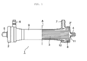
- Figure 1 illustrates a partially sectional diagram schematically showing one example of a hollow fiber membrane-based medical device of the present embodiment.
- Figure 1 shows a schematic sectional view of the hollow fiber membrane-based medical device on the right side of the alternate long and short dash line A shown at the center and shows a schematic perspective view of the hollow fiber membrane-based medical device on the left side of the alternate long and short dash line A.
- bundle 3 of a hollow fiber membrane is loaded along the longitudinal direction of tubular container 9. Both ends of the bundle of the hollow fiber membrane 3 are embedded in potting resins 8, respectively, so that the internal side of the hollow fiber membrane 3 is isolated from the external side thereof and that the hollow fiber membrane 3 is fixed at both ends of the tubular container 9.
- Headers 2 and 2' having a nozzle 4 or 5 serving as a fluid inlet and/or outlet are provided on the end faces of the potting resins 8, respectively, where the internal side of the hollow fiber membrane 3 is open. At least one of ports 6 and 7 serving as a fluid inlet and/or outlet is provided on the side of the tubular container 9. Nozzle plugs and port plugs described later can be attached to the nozzles 4 and 5 and the ports 6 and 7, respectively.
- a first space 11 is provided between the internal side of the hollow fiber membrane and the inner surface of each header, while a second space 12 is provided between the external side of the hollow fiber membrane 3 and the inner surface of the tubular container.
- the tubular container 9 which is a container having the inner space molded with the insulating material, is used for accommodating the hollow fiber membrane described later in the hollow fiber membrane-based medical device of the present embodiment.
- the tubular container 9 is not particularly limited by shape, dimension, etc., and any of those conventionally known in the art can be applied to the present invention.
- the insulating material refers to a material having a volume resistivity larger than 5 ⁇ 10 13 ⁇ cm.
- Examples of the insulating material for the tubular container 9 may include polypropylene resins, polystyrene resins, polymethyl methacrylate resins, polyethylene terephthalate resins, nylon 6 resins, polysulfone resins, polyacrylonitrile resins, polycarbonate resins, ABS resins, and styrene-butadiene copolymer resins.
- the polypropylene resins, the polystyrene resins, the polyacrylonitrile resins, and the styrene-butadiene copolymer resins are preferable because these resins require only low cost, are highly versatile in the field of medical members, and have proven high safety.
- the styrene-butadiene copolymer resins are particularly preferable, though the insulating material according to the present invention is not limited to them.
- the hollow fiber membrane 3 which is an embodiment of the filter medium constituting the hollow fiber membrane-based medical device of the present embodiment, performs the component separation (filtration, adsorption, etc.) of a solution to be treated in the hollow fiber membrane-based medical device of the present embodiment.
- the hollow fiber membrane 3 is not particularly limited by shape, dimension, fractionation characteristics, etc. and can be selected appropriately according to the use purpose.
- a material for the hollow fiber membrane 3 is selected from materials sterilizable with an electron beam. Examples thereof may include, but not limited to, cellulose polymers, polysulfone polymers, polyacrylonitrile polymers, polymethyl methacrylate polymers, polyvinyl polymers (including ethylene vinyl alcohol copolymers), polyamide polymers, polyester polymers, and polyolefin polymers.
- polysulfone polymers which are aromatic compounds, are preferable because these polymers are particularly excellent in radiation resistance, also very resistant to heat or chemical treatment, and also excellent in safety.
- the hollow fiber membrane 3 can be produced by a technique conventionally known in the art. A resin material is dissolved in a predetermined solvent to prepare a dope, which can then be spun to prepare the hollow fiber membrane 3. When a hydrophobic polymer is used as a base material for the hollow fiber membrane 3, a hydrophilic polymer is further used. In general, these polymers are blended using a common solvent therefor to prepare a dope, with which the hollow fiber membrane 3 is formed so that hydrophilicity is imparted thereto.
- the hydrophilic polymer may include polyvinylpyrrolidone (PVP), polyethylene glycol, polyvinyl alcohol, and polypropylene glycol.
- polyvinylpyrrolidone is preferable in terms of hydrophilicity-imparting effect or safety, though the hydrophilic polymer according to the present invention is not particularly limited to them.
- the hydrophilic polymer is PVP
- examples of the common solvent may include solvents such as dimethylacetamide (hereinafter, referred to as DMAC), dimethyl sulfoxide, N-methyl-2-pyrrolidone, dimethylformamide, sulfolane, and dioxane, and a mixed solvent of two or more of these solvents.
- the dope may be supplemented with a predetermined additive such as water to control the pore size of the hollow fiber membrane 3 of interest.
- the hollow fiber membrane 3 is formed using a tube-in-orifice-type spinneret.
- the dope and an inner solution for the dope are simultaneously discharged into air from an orifice of the spinneret and from a tube, respectively.
- Water or an inner solution composed mainly of water can be used as the inner solution. Its composition or the like can be determined according to the permeability of the hollow fiber membrane of interest.
- a mixed solution of water with the solvent used in the dope is preferably used.
- an aqueous solution containing 0 to 65% by mass of DMAC is used.
- the dope thus discharged from the spinneret together with the inner solution is traveled in an air gap portion and introduced and dipped in a coagulation bath (composed mainly of water) placed below the spinneret to complete coagulation.
- a coagulation bath composed mainly of water placed below the spinneret to complete coagulation.
- the hollow fiber membrane in a wet state is wound up using a winding machine to obtain a bundle of the hollow fiber membrane, which is then dried.
- the hollow fiber membrane may be dried in a dryer to obtain a bundle of the hollow fiber membrane.
- the bundle of the hollow fiber membrane 3 is loaded along the longitudinal direction of the tubular container 9 and fixed at both ends of the tubular container 9.
- the bundle of the hollow fiber membrane 3 is inserted in the tubular container 9 having a fluid inlet and/or outlet.
- the potting resins 8 are injected to both ends of the bundle of the hollow fiber membrane 3.
- the resulting tubular container 9 is centrifuged around the central axis in the longitudinal direction so that layers of the potting resins 8 are formed at both ends of the bundle of the hollow fiber membrane 3 to fix these ends to both ends of the tubular container, respectively, by sealing.
- the potting resins 8 have the function of sealing both ends of the bundle of the hollow fiber membrane 3.
- Examples of materials for the potting resins 8 may include, but not limited to, polyurethane resins, epoxy resins, and silicon resins.
- the headers 2 and 2' face both end faces of the hollow fiber membrane 3 and are provided at both ends of the tubular container 9, respectively.
- materials for the headers 2 and 2' may include polypropylene resins, polystyrene resins, polymethyl methacrylate resins, polyethylene terephthalate resins, nylon 6 resins, polysulfone resins, polyacrylonitrile resins, polycarbonate resins, ABS resins, and styrene-butadiene copolymer resins.
- the polypropylene resins, the polystyrene resins, the polyacrylonitrile resins, and the styrene-butadiene copolymer resins are preferable because these resins require only low cost, are highly versatile in the field of medical members, and have proven high safety.
- the styrene-butadiene copolymer resins are particularly preferable, though the material according to the present invention is not limited to them.
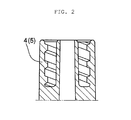
- the nozzles 4 and 5 of the headers 2 and 2' each constitute an inlet and/or an outlet for flowing a fluid into the tubular container and/or effusing a fluid from the container, together with nozzle plugs described later.
- Figure 2 illustrates a schematic sectional diagram of the nozzles 4 and 5 of the headers 2 and 2'.
- structures described in 4.4.3 connected parts on the blood side of hemodialyzers, hemodialysis filters, and hemofilters
- JIS T 3250:2005 hemodialyzers, hemodialysis filters, hemofilters, and blood concentrators
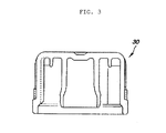
- Figure 3 illustrates a schematic sectional diagram of each nozzle plug 30.
- the nozzle plugs 30 have the function of blocking the openings of the nozzles 4 and 5 from the outside and may each have, on the internal side of its top portion, a cylindrical projection to be interlocked with the lateral surface of each of the nozzles 4 and 5 and a cylindrical projection to be interlocked with the hollow portion of each nozzle.
- the nozzle plugs 30 can be sterilized, in a state attached to the nozzles 4 and 5, by electron beam irradiation described later to thereby maintain the sterilized state of the first space 11 shown in Figure 1 .
- the inlet and/or the outlet have a portion formed of a polymer material having a volume resistivity of 5 ⁇ 10 13 ⁇ cm or smaller.
- the portion having a volume resistivity of 5 ⁇ 10 13 ⁇ cm or smaller may be a portion or the whole of each nozzle plug 30.
- Specific examples of materials for the nozzle plugs 30 may include, but not limited to, polyethylene resins, polypropylene resins, polycarbonate resins, polystyrene resins, polyamide resins, polyacetal resins, and silicon resins.
- the polyethylene resins and the polypropylene resins are preferable because these resins have adhesion properties or plugging properties based on moderate hardness and are already versatile as wrapping-type plugs (described later) or squeezed-type plugs (described later).
- the ports 6 and 7 each constitute an inlet and/or an outlet for flowing the fluid into the tubular container and/or for effusing the fluid from the container, together with port plugs described later.
- Figure 4 illustrates a schematic perspective diagram of the ports 6 and 7 provided on the side of the tubular container 9 constituting the hollow fiber membrane-based medical device of the present embodiment.
- structures described in 4.4.4 connected parts on the dialysate side of hemodialyzers and hemodialysis filters) of JIS T 3250:2005 (hemodialyzers, hemodialysis filters, hemofilters, and blood concentrators) can be applied to the structures of the ports 6 and 7.
- the ports 6 and 7, as shown in the broken lines in Figure 4 are in a tubular form having an internal hollow portion communicated with the inside of the tubular container 9 and can be opened and closed by the attachment and removal of their respective port plugs described later.
- FIG. 5(A) illustrates a schematic sectional diagram of each port plug 20.
- Figure 5(B) illustrates a schematic sectional diagram of the port plug 20 in a state attached to the port 6 or 7.
- the port plugs 20, as shown in Figure 5(A) each have a top portion 20a having the function of blocking the opening of each of the ports 6 and 7 from the outside and may each have a cylindrical projection 20b to be interlocked with the lateral surface of each of the ports 6 and 7 and a cylindrical projection 20c to be interlocked with the hollow portion of each of the ports 6 and 7.
- the port plugs 20 are attached to the ports 6 and 7 such that the ports 6 and 7 are covered to their bases as shown in Figure 5(B) .
- the port plugs can be subjected to sterilization described later to thereby maintain the sterilized states of the second space 12 and the lateral surfaces of the ports 6 and 7 until immediately before use of the hollow fiber membrane-based medical device.
- the port plugs 20 are not particularly limited by shape. Specific examples thereof may include: as shown in Figure 5(A) , wrapping-type plugs having a shape to wrap the whole port 6 or 7; and as shown as a plug 200 in Figures 6(A) and 6(B) , squeezed-type plugs having a shape to produce hermeticity by contacting the partial surface of the port plug 200 with the inner wall surface in the internal space (second space 12) of the port 6 or 7. As shown in Figure 5(A) , the wrapping-type plugs having the shape to wrap the whole port 6 or 7 are superior in the function of maintaining the sterilized state.
- each plug attached to the ports 6 and 7 and the nozzles 4 and 5 of the headers 2 and 2' may be of any type, and plugs of the other types may be used.
- the inlet and/or the outlet have a portion formed of a polymer material having a volume resistivity of 5 ⁇ 10 13 ⁇ cm or smaller, i.e., their respective predetermined plugs.
- the portion having the volume resistivity of 5 ⁇ 10 13 ⁇ cm or smaller may be a portion or the whole of each port plug 30.
- Examples of materials for the port plugs 20, 200 include, but not limited to, polyethylene resins, polypropylene resins, polycarbonate resins, polystyrene resins, polyamide resins, polyacetal resins, and silicon resins.
- the polyethylene resins and thepolypropylene resins are preferable because these resins have adhesion properties or plugging properties based on moderate hardness and are already versatile as wrapping-type plugs or squeezed-type plugs. These resins may be used alone or in combination as long as the polymer material having the volume resistivity of 5 ⁇ 10 13 ⁇ cm or smaller can be obtained.
- these resins can be combined with an antistatic agent or a conductive polymer material to thereby more conveniently obtain materials for the plugs suitable for the purpose of the present invention.
- the hollow fiber membrane-based medical device is basically used in contact with a body fluid, a method involving blending predetermined resins with antistatic agents and molding this into a predetermined component is more preferable than a method involving coating the surface of a constituent component with the antistatic agents, from a safety standpoint.
- the antistatic agents to be blended with thermoplastic resin may include polymer-based antistatic agents such as antistatic agents having a polyoxyalkylene chain (e.g., Japanese Patent Laid-Open Nos.
- antistatic agents comprising a copolymer of polyether having an oxyethylene group and polyether having no oxyethylene group, wherein the oxyethylene group moiety has a degree of crystallinity in a particular range
- antistatic agents commercially available comprising block polymer having polyether as a hydrophilic segment, surfactant-based antistatic agents, conductive fillers (carbon black, etc.), and conductive ABS resins.
- the portion formed of a polymer material having thye volume resistivity of 5 ⁇ 10 13 ⁇ cm or smaller, which constitutes each port plug 20 or 200, will be described with reference to specific examples shown in Figures 7(A) to 7(T) .
- the portions represented by reference numerals 21 and 210 each depict a portion formed of a polymer material having the volume resistivity of 5 ⁇ 10 13 ⁇ cm or smaller, while the portions represented by reference numerals 22 and 220 depict a portion formed of a polymer material having the volume resistivity larger than 5 ⁇ 10 13 ⁇ cm.
- Each of these portions may be composed of one component or a combination of a plurality of components.
- the portion having the volume resistivity of 5 ⁇ 10 13 ⁇ cm or smaller should be provided in contact with the second space 12 constituting the hollow fiber membrane-based medical device and also with the external space of the main body of the hollow fiber membrane-based medical device in a seamless way.
- electric charge accumulated in the main body of the hollow fiber membrane-based medical device can be passed through only the portion having the volume resistivity of 5 ⁇ 10 13 ⁇ cm or smaller and dissipated to the external space of the main body of the hollow fiber membrane-based medical device. Even if the portion having the volume resistivity of 5 ⁇ 10 13 ⁇ cm or smaller is not brought into contacted with the second space 12 in the hollow fiber membrane-based medical device or the external space of the main body, or both, this portion provided in a portion of the plug can sufficiently facilitate the dissipation, from the main body, of electric charge accumulated in the main body of the hollow fiber membrane-based medical device and contributes to the effective prevention of dielectric breakdown in the hollow fiber membrane-based medical device.
- the constituent members other than the port plugs and the nozzle plugs may also be formed of a material having the volume resistivity of 5 ⁇ 10 13 ⁇ cm or smaller.
- this material can be combined, if necessary, with the commercially available antistatic agent or conductive polymer material to thereby relatively easily achieve the volume resistivity of 5 ⁇ 10 13 ⁇ cm or smaller.
- the volume resistivity also called volume resistivity value
- the volume resistivity can be measured specifically at 22°C in a humidity environment of 60% RH using a test piece of 100 ⁇ 100 mm and a predetermined measurement apparatus, for example, ULTRA HIGH RESISTANCE METER R8340A, TEST FIXTURE R12702A manufactured by Advantest Corp. according to JIS K6911. If the volume resistivity exceeds 5 ⁇ 10 13 ⁇ cm, electric charge accumulated in the main body of the hollow fiber membrane-based medical device due to electron beam irradiation performed for sterilization treatment cannot sufficiently be dissipated. The resulting accumulated electric charge easily causes dielectric breakdown in the hollow fiber membrane-based medical device.
- each plug constituting the hollow fiber membrane-based medical device of the present embodiment should have a portion formed of a polymer material having small volume resistivity.
- typical polymer materials having sufficiently small volume resistivity may present problems such as high production cost, small mechanical strength, and difficult attachment to each port. It is thus preferred to select a material according to the purpose.
- each plug constituting the inlet and/or the outlet in the hollow fiber membrane-based medical device has the volume resistivity of 5 ⁇ 10 13 ⁇ cm or smaller, preferably 1 ⁇ 10 -2 to 5 ⁇ 10 13 ⁇ cm, more preferably 5 ⁇ 10 4 to 5 ⁇ 10 13 ⁇ cm.
- the hollow fiber membrane-based medical device of the present embodiment is preferably constituted such that the port plug 20 or 200 has the portion formed of a polymer material having the volume resistivity of 5 ⁇ 10 13 ⁇ cm or smaller, at least in a partial top portion thereof (the top portions of the port plugs 20 and 200 are represented by 20a in Figures 5(A) and 5(B) and 200a in Figures 6(A) and 6(B) , respectively).
- the phrase "at least in a partial top portion thereof” may be a portion or the whole of the top portion of the plug and also means only the top portion or the top portion plus the other portion.
- the port plug 20 or 200 has the portion having the volume resistivity of 5 ⁇ 10 13 ⁇ cm or smaller, at least in a partial top portion thereof (in 20a or 200a), it is further preferred that this portion should be brought into contact on the outer surface side of the port plug 20 or 200 with the external space of the hollow fiber membrane-based medical device and on the inner surface side of the port plug with the second space 12 in a seamless way.
- Examples of materials for the portion constituting at least the partial top portion (in 20a or 200a) and having the volume resistivity of 5 ⁇ 10 13 ⁇ cm or smaller may include, but not limited to, polyethylene resins, polypropylene resins, polycarbonate resins, polystyrene resins, polyamide resins, polyacetal resins, and silicon resins, as in the plugs.
- polyethylene resins and polypropylene resins are preferable because these resins have adhesion properties or plugging properties based on moderate hardness and are already versatile as wrapping-type plugs or squeezed-type plugs. These resins may be used alone or in combination as long as the polymer material having volume resistivity of 5 ⁇ 10 13 ⁇ cm or smaller can be obtained.
- these resins can be combined with an antistatic agent or a conductive polymer material to thereby more conveniently obtain materials suitable for the purpose of the present invention.
- materials for the portion (member) other than the portion constituting at least the partial top portion (in 20a or 200a) and having the volume resistivity of 5 ⁇ 10 13 ⁇ cm or smaller may include polyethylene resins, polypropylene resins, polycarbonate resins, polystyrene resins, polyamide resins, polyacetal resins, and silicon resins. In terms of strength, it is preferred that this portion (member) should be formed of a polymer material having the volume resistivity larger than 5 ⁇ 10 13 ⁇ cm.
- polyethylene resins and polypropylene resins are preferable because these resins have adhesion properties or plugging properties based on moderate hardness and are already versatile as wrapping-type plugs or squeezed-type plugs.
- plugs constituted such that the port plug 20 or 200 has, at least in a partial top portion thereof, the portion having the volume resistivity of 5 ⁇ 10 13 ⁇ cm or smaller correspond to those shown in Figures 7(A), 7(C), 7(D), and 7(F) to 7(T) .
- the low-volume resistivity portion constituting each port plug and formed of a polymer material having vthe olume resistivity of 5 ⁇ 10 13 ⁇ cm or smaller is provided in contact with the second space 12 constituting the hollow fiber membrane-based medical device and also with the external space of the main body of the hollow fiber membrane-based medical device in a seamless way.
- This constitution can produce the effect of more efficiently and reliably preventing dielectric breakdown.
- electric charge accumulated in the main body of the hollow fiber membrane-based medical device can be passed through only the low-volume resistivity portion formed of a polymer material having volume resistivity of 5 ⁇ 10 13 ⁇ cm or smaller and dissipated to the external space of the main body of the hollow fiber membrane-based medical device.
- the resulting hollow fiber membrane-based medical device can maintain practically sufficient strength as a whole, can prevent increase in eluted materials, and can overcome the problems associated with dielectric breakdown, which have been tackled by the conventional techniques.
- the low-volume resistivity portion constituting each port plug and formed of a polymer material having the volume resistivity of 5 ⁇ 10 13 ⁇ cm or smaller should be limited only to the top (represented by 20a in Figures 5(A) and 5(B) or 200a in Figures 6(A) and (B) ) portion of the port plug.
- the size of the low-volume resistivity portion formed of a polymer material having the volume resistivity of 5 ⁇ 10 13 ⁇ cm or smaller For effectively preventing the occurrence of dielectric breakdown attributed to electron beam irradiation, it is preferred to increase the size of the low-volume resistivity portion formed of a polymer material having the volume resistivity of 5 ⁇ 10 13 ⁇ cm or smaller.
- typical polymer materials having the volume resistivity of 5 ⁇ 10 13 ⁇ cm or smaller may present problems such as high production cost, small mechanical strength derived from increase in occupied volume in the port plug, and difficult attachment to each port.
- Moderate hardness leading to plugging properties or moderate adhesion properties can be obtained by controlling as described above the low-volume resistivity portion formed of a polymer material having volume resistivity of 5 ⁇ 10 13 ⁇ cm or smaller. From the viewpoint of also obtaining sufficient strength, it is preferred that only the whole or a portion of the top portion 20a or 200a should have such low volume resistivity and that the portion other than the top portion of the port plug should be formed of a polymer material having the volume resistivity larger than 5 ⁇ 10 13 ⁇ cm.
- the port plug 20 or 200 can be prepared by a molding method conventionally known in the art, for example, an injection molding method.
- the port plug 20 or 200 as described above, has the low-volume resistivity portion having the volume resistivity of 5 ⁇ 10 13 ⁇ cm or smaller, at least in a partial top portion thereof (in 20a or 200a)
- the port plug can be prepared, for example, by a two-color molding method so that the port plug has in combination portions differing in volume resistivity.
- the low-volume resistivity portion constituting at least the partial top portion (in 20a or 200a) and the other portion may be injection-molded separately to prepare their respective components, which are combined in downstream operation to prepare the port plug.
- hollow fiber membrane-based medical devices are broadly classified into two types: wet type in which the hollow inside of the hollow fiber membrane or the gap between the hollow fiber membrane and a container is filled with an aqueous medium; and non-wet type in which such space is not filled with an aqueous medium.
- the hollow fiber membrane-based medical devices of the latter type may be categorized as dry type having a hollow fiber membrane with a low water content, i.e., a small percent of water, and semidry type (also called half-wet type) having a membrane wetted to some extent with water, a humectant, or the like.
- semidry type also called half-wet type
- the hollow fiber membrane-based medical device of the present embodiment can be prepared as any type of hollow fiber membrane-based medical device according to the purpose.
- an antioxidant or buffer mixed with pure water or a solvent can be generally used as an aqueous medium.
- the antioxidant may include, but not particularly limited to, sodium pyrosulfite, acetone sodium bisulfite, sodium formaldehyde sulfoxylate, sodium hydrosulfite, and 1-ascorbic acid.
- the buffer may include, but not particularly limited to, phosphate buffers, trishydroxymethylaminomethane buffers, acetate buffers, citrate buffers, and borate buffers.
- the solvent may include, but not particularly limited to, methanol, ethanol, glycerin, propylene glycol, and isopropanol.
- a humectant can be used preferably, which has the function of protecting a hydrophilic polymer from deterioration, and which is easily carried on a membrane surface by virtue of moderate viscosity, and simultaneously satisfies the requirements that: it does not form a strong chemical bond with a hydrophobic polymer or a hydrophilic polymer; and it is easily washed off with a physiological aqueous solution.
- Examples thereof may include polyhydric alcohols such as glycerin, mannitol, glycols (e.g., ethylene glycol, diethylene glycol, propylene glycol, and tetraethylene glycol), and polyglycols (e.g., polyethylene glycol).
- polyhydric alcohols such as glycerin, mannitol, glycols (e.g., ethylene glycol, diethylene glycol, propylene glycol, and tetraethylene glycol), and polyglycols (e.g., polyethylene glycol).
- glycols e.g., ethylene glycol, diethylene glycol, propylene glycol, and tetraethylene glycol
- polyglycols e.g., polyethylene glycol
- an aqueous solution of glycerin or polyethylene glycol is more preferable in terms of its actual achievements as pore size-retaining agents or surface modifiers for hollow fiber membranes for blood purification.
- the hollow fiber membrane-based medical device of the present embodiment is sterilized by electron beam irradiation.
- the irradiation dose of the electron beams is preferably 5 to 60 kGy (kilogray), more preferably 15 to 50 kGy, further preferably 15 to 45 kGy.
- the feature of the hollow fiber membrane-based medical device of the present embodiment is that the sterilization treatment is performed in a state where the port plugs 20 and the nozzle plugs 30 are attached to the ports 6 and 7 on the side of the tubular container 9 and the nozzles 4 and 5 of the headers 2 and 2', respectively. It is also preferred to perform the sterilization treatment by electron beam irradiation in a state where the hollow fiber membrane-based medical device is packaged in a sterilization bag.
- the sterilization treatment may be performed in a state where the hollow fiber membrane-based medical device is not packaged in a sterilization bag or in a state where the hollow fiber membrane-based medical device without the plugs attached thereto is packaged in a sterilization bag. From the viewpoint of maintaining the sterilized state of the hollow fiber membrane-based medical device until immediately before its use or for immediately using the hollow fiber membrane-based medical device in medical practice, it is preferred to perform the sterilization treatment in a state where the hollow fiber membrane-based medical device with the plugs attached thereto is packaged in a sterilization bag.
- Examples of materials for the sterilization bag for use as a package in the sterilization treatment may include polyvinylidene chloride films, polyvinyl alcohol films, biaxial stretched polyvinyl alcohol films, polyvinylidene chloride-coated biaxial stretched polyalcohol films, polyester/aluminum/polyethylene laminate sheets, aluminum foils, and films having a polyethylene/nylon bilayer structure.
- a method for sealing a film having a polyethylene/nylon bilayer structure by lamination is preferable from the viewpoint of bag productivity or cost, though the sterilization bag according to the present invention is not particularly limited to them.
- the medical device of the present embodiment can be used in a wide range of applications. Examples thereof may include hemodialyzers, hemodialysis filters, hemofilters, continuous hemodialysis filters, continuous hemofilters, plasma separators, plasma fractionators, plasma component adsorbers, virus removers, virus adsorbers, blood concentrators, plasma concentrators, ascitic fluid filters, and ascitic fluid concentrators.
- the medical device of the present embodiment can be applied to various medical devices utilizing filtration characteristics or selective adsorption characteristics (involving hollow fiber membranes on which ligands that exhibit interaction with substances to be adsorbed are immobilized) possessed by the hollow fiber membrane.
- Each hollow fiber membrane-based medical device was completely immersed in water.
- a pressure of 150 kPa was applied to the hollow fiber membrane-based medical device by air supply to the inside thereof, while the hollow fiber membrane-based medical device was kept for 30 seconds.
- the occurrence of air bubbles from a dielectric breakdown spot was observed to confirm the presence or absence of dielectric breakdown.
- This in-water positive pressure test was conducted for each of the first and second spaces in the hollow fiber membrane-based medical device. When the occurrence of dielectric breakdown was confirmed by either of the methods described in (Visual observation) and (In-water positive pressure test) above, the hollow fiber membrane-based medical device was determined to have dielectric breakdown.
- the ratio of the number of hollow fiber membrane-based medical devices having dielectric breakdown to the total number of prepared hollow fiber membrane-based medical devices was indicated by percentage.
- test piece Materials constituting port plugs of Examples 1 to 3 and Comparative Examples 1 to 2 described later and portions having predetermined low volume resistivity or materials constituting port plugs of Examples 4 to 7 and Comparative Examples 3 to 5 were separately processed into a test piece of 100 ⁇ 100 mm.
- the test piece was assayed at 22°C in a humidity environment of 60% RH using "ULTRA HIGH RESISTANCE METER R8340A, TESTFIXTURE R12702A" manufactured by Advantest Corp. according to JIS K6911.
- a semidry-type hollow fiber membrane-based medical device was obtained under the same conditions as in Example 1 except that a port on the main body was capped with a port plug formed of one component molded from polyolefin resin mixed with conductive carbon. Table 1 below shows the incidence of dielectric breakdown in this hollow fiber membrane-based medical device and the volume resistivity of the port plug attached to the port on the main body.
- a semidry-type hollow fiber membrane-based medical device was obtained under the same conditions as in Example 1 except that:
- a semidry-type hollow fiber membrane-based medical device was obtained under the same conditions as in Example 1 except that a port on the main body was capped with a port plug formed of one component made of polyethylene (manufactured by Prime Polymer Co., Ltd., registered trademark: HI-ZEX). Table 1 below shows the incidence of dielectric breakdown in this hollow fiber membrane-based medical device and the volume resistivity of the port plug attached to the port on the main body.
- a semidry-type hollow fiber membrane-based medical device was obtained under the same conditions as in Example 1 except that a port on the main body was capped with a port plug formed of one component molded from a polyethylene (manufactured by Prime Polymer Co., Ltd., registered trademark: HI-ZEX) chip and a polyethylene-b-polyether block polymer (manufactured by Sanyo Kasei Industries, Ltd., Pelestat) chip added at a mixing ratio of 92%:8% to an injection molding machine.
- Table 1 below shows the incidence of dielectric breakdown in this hollow fiber membrane-based medical device and the volume resistivity of the port plug attached to the port on the main body.
- Example 1 Irradiation dose Incidence of dielectric breakdown Volume resistivity ( ⁇ cm)
- Example 1 35kGy 0% 3.4 ⁇ 10 13
- Example 2 35kGy 0% 8.2 ⁇ 10 4
- Example 3 57kGy 0% 9.0 ⁇ 10 12
- Comparative Example 1 35kGy 73% 4.5 ⁇ 10 17
- Comparative Example 2 35kGy 40% 4.0 ⁇ 10 14
- the hollow fiber membrane-based medical devices of Examples 1 to 3 having the plug formed of a polymer material having volume resistivity of 5 ⁇ 10 13 ⁇ cm or smaller were all able to effectively prevent the occurrence of dielectric breakdown.
- a semidry-type hollow fiber membrane-based medical device was obtained under the same conditions as in Example 4 except that ports 6 and 7 on the main body were capped with port plugs having a shape shown in [ Figure 7(G) ], wherein the portion represented by reference numeral 21, which was a partial top portion of the port plug in [ Figure 7(G) ], was formed of one component molded from polyolefin resin mixed with conductive carbon, and the portion represented by reference numeral 22 was formed of one component made of polyethylene (manufactured by Prime Polymer Co., Ltd., registered trademark: HI-ZEX). Table 2 below shows the incidence of dielectric breakdown in this hollow fiber membrane-based medical device and the volume resistivity of the portion represented by reference numeral 21 in the port plugs attached to the ports on the main body.
- a semidry-type hollow fiber membrane-based medical device was obtained under the same conditions as in Example 4 except that the irradiation dose of electron beams was changed to 57 kGy.
- Table 2 below shows the incidence of dielectric breakdown in this hollow fiber membrane-based medical device and the volume resistivity of the portion represented by reference numeral 21 in the port plugs attached to the ports on the main body.
- a semidry-type hollow fiber membrane-based medical device was obtained under the same conditions as in Example 4 except that:
- a semidry-type hollow fiber membrane-based medical device was obtained under the same conditions as in Example 4 except that ports 6 and 7 on the main body were capped with port plugs having a shape shown in [ Figure 7(G) ], wherein the portion represented by reference numeral 21, which was a partial top portion of the port plug in [ Figure 7(G) ], was formed of one component molded from a polyethylene (manufactured by Prime Polymer Co., Ltd., registered trademark: HI-ZEX) chip and a polyethylene-b-polyether block polymer (manufactured by Sanyo Kasei Industries, Ltd., Pelestat) chip added at a mixing ratio of 92%:8% by mass to an injection molding machine, and the portion represented by reference numeral 22 was formed of one component made of polyethylene (manufactured by Prime Polymer Co., Ltd., registered trademark: HI-ZEX).
- Table 2 below shows the incidence of dielectric breakdown in this hollow fiber membrane-based medical device and the volume resistivity of the portion represented by reference numeral
- a semidry-type hollow fiber membrane-based medical device was obtained under the same conditions as in Example 4 except that ports 6 and 7 on the main body were capped with port plugs having a shape shown in [ Figure 7(C) ], wherein the portion represented by reference numeral 21, which was the top portion of the port plug in [ Figure 7(C) ], was formed of one component molded from a polyethylene (manufactured by Prime Polymer Co., Ltd., registered trademark: HI-ZEX) chip and a polyethylene-b-polyether block polymer (manufactured by Sanyo Kasei Industries, Ltd., Pelestat) chip added at a mixing ratio of 92%:8% by mass to an injection molding machine, and the portion represented by reference numeral 22 was formed of one component made of polyethylene (manufactured by Prime Polymer Co., Ltd., registered trademark: HI-ZEX).
- Table 2 below shows the incidence of dielectric breakdown in this hollow fiber membrane-based medical device and the volume resistivity of the portion represented by reference numeral 21 in
- a semidry-type hollow fiber membrane-based medical device was obtained under the same conditions as in Example 4 except that ports 6 and 7 on the main body were capped with port plugs each formed of one component made of polyethylene (manufactured by Prime Polymer Co., Ltd., registered trademark: HI-ZEX), wherein the shape of each port plug was the same as in [ Figure 7(C) or 7(G) ], while the whole port plug was made of polyethylene only.
- Table 2 below shows the incidence of dielectric breakdown in this hollow fiber membrane-based medical device and the volume resistivity of the port plugs attached to the ports on the main body.
- a medical device of the present invention has industrial applicability as various medical devices for hemodialysis, hemodiafiltration, hemofiltration, continuous hemodiafiltration, continuous hemofiltration, plasma exchange, double filtration plasma exchange, virus removal, blood concentration, ascitic fluid filtration/concentration, adsorption, etc., in medical practice.
Landscapes
- Health & Medical Sciences (AREA)
- Chemical & Material Sciences (AREA)
- Chemical Kinetics & Catalysis (AREA)
- Engineering & Computer Science (AREA)
- Heart & Thoracic Surgery (AREA)
- Urology & Nephrology (AREA)
- Public Health (AREA)
- Veterinary Medicine (AREA)
- Manufacturing & Machinery (AREA)
- General Health & Medical Sciences (AREA)
- Animal Behavior & Ethology (AREA)
- Life Sciences & Earth Sciences (AREA)
- Hematology (AREA)
- Biomedical Technology (AREA)
- Anesthesiology (AREA)
- Vascular Medicine (AREA)
- Emergency Medicine (AREA)
- Epidemiology (AREA)
- External Artificial Organs (AREA)
- Separation Using Semi-Permeable Membranes (AREA)
Abstract
Description
- The present invention relates to a medical device and a hollow fiber membrane-based medical device.
- In recent years, there has been an advance in the medical application of techniques of, particularly, hollow fiber membranes, among medical devices comprising a predetermined filter medium in the inner space. Such hollow fiber membrane-based medical devices are frequently used in, for example, artificial kidneys for use in the hemodialysis therapy of chronic renal failure patients, plasma separators for use in plasma exchange therapy involving discarding a patient's plasma and infusing instead fresh frozen plasma or an albumin solution, and plasma fractionators for use in double filtration plasma exchange therapy involving removing high-molecular-weight substances in the patient's plasma.
- The hollow fiber membrane-based medical devices come into contact with the patient's body fluid, such as blood, and thus, must be sterilized for use.
Examples of sterilization methods may include heat sterilization, chemical sterilization, and irradiation sterilization. These sterilization methods are appropriately selected in consideration of the thermal and chemical properties of the hollow fiber membrane-based medical devices.
Particularly, electron beam sterilization, one approach of the irradiation sterilization, is known to be highly useful, because this sterilization method is free from exposure to high temperature as in heat sterilization, chemical agents remaining in medical devices as in chemical sterilization, or the need for storing radioactive substances in large amounts as in γ ray sterilization, another approach of the irradiation sterilization (see e.g., Patent Document 1). - Electron beams, however, are less permeable to objects than γ rays, and the distance penetrated thereby depends on the density of a substance to be irradiated. For this reason, conventional targets for electron beam sterilization are mainly those having a relatively uniform shape and composed of a single member, such as surgical gloves or surgical gowns. When the hollow fiber membrane-based medical device, which is thick and has a high-density portion, is subjected to electron beam irradiation, this irradiation might insufficiently permeate some portions and cause a large dose distribution (ratio between the maximum dose and the minimum dose) among sites, resulting in the manifestation of problems such as material deterioration or eluted materials.
Specifically, irradiation on the basis of the maximum dose causes insufficient sterilization at a position of the minimum dose. On the contrary, reliable sterilization by irradiation on the basis of a site of the minimum dose may cause excessive irradiation at a position of the maximum dose, resulting in material deterioration or staining.
Particularly, if a hydrophilic polymer used as a constituent material in the hollow fiber membrane becomes deteriorated, its hydrophilicity is impaired. The resulting device has reduced blood compatibility.
As described above, it is not easy to uniformly irradiate objects having a complicated shape and different densities among sites, as in the hollow fiber membrane-based medical devices, with an electron beam. Thus, the electron beam sterilization is accompanied by problems based on nonuniform irradiation. - Thus, as measures for uniformly irradiating objects having a complicated shape and different densities among sites, as in the hollow fiber membrane-based medical devices, with an electron beam, studies have been made mainly from two viewpoints: a materials chemical approach and an approach based on a sterilization step.
First, for the materials chemical approach, a large number of techniques involving kneading an additive such as a radical-trapping agent or an antioxidant into a resin material or allowing such an additive to coexist in the vicinity of resin are known and have been studied extensively as methods for suppressing deterioration during exposure to radiation including electron beams. These materials chemical approaches have such advantages that they eliminate the need for drastically renovating irradiation facilities and achieve efficient production without prolonging irradiation cycle time.
Meanwhile, the problems of the materials chemical approach are that: many additives cannot be adopted for extracorporeal circulation-based blood purification apparatuses from a safety standpoint; and approaches for the hollow fiber membrane-based medical devices have mostly been made concrete as improvements dedicated to material deterioration during γ ray sterilization and are thus utilized in a limited range (see e.g.,Patent Documents 2 and 3). - Next, a method involving raising an accelerating voltage has received attention as the approach based on a sterilization step.
For example, there are disclosed a technique of performing irradiation at high accelerating voltage for the electron beam sterilization of hollow fiber membrane-based dialysis apparatuses or artificial lungs, while reducing dose distribution using a shielding material (see e.g., Patent Document 4) and an irradiation method combining an entire irradiation step and a partial shielding step (see e.g., Patent Document 5).
Also, Patent Document 1 discloses a technique of achieving a uniform irradiation dose as a whole by irradiating a hollow fiber membrane-based module having the particular product of density and thickness with an electron beam in 3 or more directions.
These approaches based on a sterilization step can overcome the challenge of reducing dose distribution. However, all of them disadvantageously have poor workability and poor efficiency in the practice of sterilization methods for mass products. - Furthermore, studies have been made in terms of both the materials chemical approach and the approach based on a sterilization step to prevent material deterioration and achieve a uniform absorbed dose of electron beams.
However, the effect of improving (reducing) the adsorbed dose distribution of electron beams becomes insufficient with the firm commitment to material protection from a materials chemical standpoint. On the contrary, the effect of efficiently treating objects to be irradiated becomes insufficient with the firm commitment to methods for individually irradiating objects to be irradiated or facilities therefor from the viewpoint of a uniform absorbed dose. - Aside from the materials chemical approach or the approach based on a sterilization step, focusing on the package form of the hollow fiber membrane-based medical device, an approach involves housing a stack structure in an electron beam-permeable case, followed by irradiation sterilization with an electron beam, the stack structure comprising: a gap layer with a particular density containing no hollow fiber membrane-based medical device; and body fluid treatment device layers with a particular density comprising tubular hollow fiber membrane-based medical devices arranged in parallel. There is disclosed a technique of thereby protecting the materials for the hollow fiber membrane-based medical devices themselves, while achieving a uniform absorbed dose (see e.g., Patent Literature 6).
- As described above, the problems associated with a nonuniform absorbed dose in the electron beam irradiation of objects to be irradiated having a complicated shape and largely different densities among sites, as in the hollow fiber membrane-based medical devices, and with material deterioration have previously been tackled by means of a devised package form, increased accelerating voltage, or multidirectional irradiation.
- Meanwhile, aside from these problems associated with material deterioration or a nonuniform absorbed dose in the electron beam sterilization step as described above, a new challenge to the electron beam sterilization step has arisen in recent years. Specifically, an insulating polymer material such as polyolefin resin is generally used as a constituent material in the hollow fiber membrane-based medical devices. Upon electron beam irradiation, electric charge accumulates in such an insulating polymer material. The accumulation of electric charge above a certain level causes undesired dielectric breakdown (see e.g.,
Patent Documents 7 and 8). -
- Patent Document 1: Japanese Patent Laid-Open No.
2000-325434 - Patent Document 2: Japanese Patent No.
3076080 - Patent Document 3: Japanese Patent No.
3432240 - Patent Document 4: Japanese Patent Laid-Open No.
8-275991 - Patent Document 5: Japanese Patent Laid-Open No.
2000-334028 - Patent Document 6: International Publication No.
2009/017227 - Patent Document 7: Japanese Patent Laid-Open No.
2000-001561 - Patent Document 8: Japanese Patent Laid-Open No.
2001-324656 - Only in a few cases, medical devices having a complicated shape such as medical devices having a predetermined filter medium in the inner space, particularly, hollow fiber membrane-based medical devices, are actually irradiated with an electron beam. Issues such as the accumulation of electric charge in objects to be irradiated and dissipation thereof have not yet been studied sufficiently.
- Nonuniform irradiation during the electron beam irradiation of medical devices having a complicated shape and largely different densities among sites has previously been tackled by means of a devised package form, increased accelerating voltage, or multidirectional irradiation as strategies for solving this problem, as described above. Some of these strategies might promote the accumulation of electric charge in a portion or the whole of an object to be irradiated containing an insulating constituent member.
- The occurrence of dielectric breakdown in a portion of a medical device, as described above, might not only cancel the sterility of the medical device but also significantly jeopardize persons receiving treatment with the medical device. For electron beam irradiation sterilization, it is thus required to overcome the challenge of achieving a uniform absorbed dose as well as to study the issues associated with the accumulation and dissipation of electric charge.
- The present inventors have conducted diligent studies on the electron beam irradiation sterilization of medical devices.
For example, when a hollow fiber membrane-based medical device is sterilized by electron beam irradiation, its irradiation dose is determined in consideration of the deterioration of members and sterility and is generally approximately 15 to 20 kGy for dry or semidry type and approximately 25 kGy even for wet type. - In order to study the problems associated with the accumulation of electric charge, the present inventors have prepared, on trial, a semidry-type hollow fiber membrane-based medical device irradiated with 35 kGy electron beams, which are an alleged excessive dose in conventional techniques, and have visually observed it. As a result, the present inventors have found dielectric breakdown signs in a portion of the hollow fiber membrane-based medical device thus sterilized.
Specifically, each dialyzer was prepared using a bundle of the hollow fiber membrane containing an aqueous glycerin solution in the hollow fiber membrane obtained by a dry/wet spinning method using a dope containing polysulfone and polyvinylpyrrolidone. Nozzles and ports were separately capped with a plug made of polyethylene. The dialyzer was packaged in a sterilization bag having a polyethylene/nylon bilayer structure and then irradiated with 35 kGy electron beams.
After the irradiation, each dialyzer was examined for the presence or absence of abnormalities resulting from electron beam irradiation itself or secondarily resulting from temporary electric charge accumulation. As a result, in some dialyzers, dielectric breakdown signs were found in the central portion of the top of the plug attached to the port on the side of the tubular container. - Thus, in light of these problems of the conventional techniques, an object of the present invention is to provide a medical device, particularly, a hollow fiber membrane-based medical device, which can effectively prevent the occurrence of dielectric breakdown even when sterilized by electron beam irradiation at a high dose.
- As a result of conducting diligent studies to attain the object, the present inventors have found that the occurrence of dielectric breakdown can be prevented by specifying at least the partial volume resistivity of components, particularly, plugs, constituting a medical device, particularly, a hollow fiber membrane-based medical device. Based on these findings, the present invention has been completed.
Specifically, the present invention is as follows: -
- [1] A hollow fiber membrane-based medical device comprising:
- a tubular container;
- a bundle of a hollow fiber membrane loaded along a longitudinal direction of the tubular container and having both ends fixed to both ends of the tubular container, respectively;
- a potting resin embedding both ends of the bundle of the hollow fiber membrane, respectively, so that the ends are fixed to the both ends of the tubular container, respectively;
- a header facing both end faces of the hollow fiber membrane and provided at the both ends of the tubular container, respectively, the header having a nozzle serving as a fluid inlet and/or outlet;
- a port provided on a side of the tubular container and serving as a fluid inlet and/or outlet;
- a nozzle plug removably attached to the respective nozzles; and
- a port plug removably attached to the port,
wherein the port plug has a portion formed of a polymer material having a volume resistivity of 5 × 10¹³ Ω·cm or smaller, and - the hollow fiber membrane-based medical device is irradiated with an electron beam.
- [2] The hollow fiber membrane-based medical device according to above [1], wherein the port plug is formed of a polymer material having a volume resistivity of 5 × 10¹³ Ω·cm or smaller.
- [3] The hollow fiber membrane-based medical device according to above [1] or [2], wherein the nozzle plug have a portion formed of a polymer material having a volume resistivity of 5 × 10¹³ Ω·cm or smaller.
- [4] The hollow fiber membrane-based medical device according to any one of above [1] to [3], wherein the nozzle plug is formed of a polymer material having a volume resistivity of 5 × 10¹³ Ω·cm or smaller.
- [5] The hollow fiber membrane-based medical device according to any one of above [1] to [4], wherein the port plug has, at least in a partial top portion thereof, the portion formed of a polymer material having a volume resistivity of 5 × 10¹³ Ω·cm or smaller.
- [6] The hollow fiber membrane-based medical device according to any one of above [1] to [5], further comprising
a first space between an internal side of the hollow fiber membrane and an inner surface of the header, and
a second space between an external side of the hollow fiber membrane and an inner surface of the tubular container,
wherein the port plug has, at least in a partial top portion thereof, the portion formed of a polymer material having a volume resistivity of 5 × 10¹³ Ω·cm or smaller, wherein the portion is brought into contact on an outer surface side of the port plug with an external space of the hollow fiber membrane-based medical device and on an inner surface side of the port plug with the second space in a seamless way. - [7] The hollow fiber membrane-based medical device according to any one of above [1] to [6], wherein the port plug has, only in a top portion thereof, the portion formed of a polymer material having a volume resistivity of 5 × 10¹³ Ω·cm or smaller.
- [8] A medical device comprising:
- a container having an inner space molded with an insulating material;
- a filter medium loaded in the inner space;
- an inlet provided on a container wall surface which defines the inner space and flowing a fluid into the container;
- an outlet provided on a container wall surface which defines the inner space and effusing a fluid from the container,
- wherein the inlet and/or the outlet have a portion formed of a polymer material having a volume resistivity of 5 × 10¹³ Ω·cm or smaller, and
- the medical device is irradiated with an electron beam.
- The present invention can provide a highly reliable medical device, particularly, hollow fiber membrane-based medical device, which can effectively prevent the occurrence of dielectric breakdown in an electron beam irradiation sterilization step.
-
- [
Figure 1] Figure 1 illustrates a partially sectional diagram schematically showing one example of a hollow fiber membrane-based medical device of the present embodiment. - [
Figure 2] Figure 2 illustrates a schematic sectional diagram of a nozzle constituting the hollow fiber membrane-based medical device of the present embodiment. - [
Figure 3] Figure 3 illustrates a schematic sectional diagram of one example of a nozzle plug. - [
Figure 4] Figure 4 illustrates a schematic diagram showing the constitution of a port constituting the hollow fiber membrane-based medical device of the present embodiment. - [
Figure 5] Figure 5(A) illustrates a schematic sectional diagram of one example of a port plug.Figure 5(B) illustrates a schematic sectional diagram of the port plug in a state attached to the port. - [
Figure 6] Figure 6(A) illustrates a schematic sectional diagram of another example of a port plug.Figure 6(B) illustrates a schematic sectional diagram of the port plug of another example in a state attached to the port. - [
Figure 7] Figures 7(A) to 7(T) illustrate schematic sectional diagrams of specific examples of port plugs. - Hereinafter, the mode for carrying out the present invention (hereinafter, referred to as the "present embodiment") will be described with reference to the drawings.
It is to be understood that the present invention is not intended to be limited to the descriptions below, and various changes may be made therein without departing from the spirit of the present invention.
In the drawings, the same reference numerals will be used to designate the same components, so that overlapping descriptions will be omitted. Positional relationships indicated by the terms "upper", "lower", "right", "left", and the like are based on those shown in the drawings, unless otherwise specified. In addition, the dimensional ratios of the drawings are not intended to be limited to those shown in the drawings. - The medical device of the present embodiment comprises: a container having an inner space molded with an insulating material; a filter medium loaded in the inner space; an inlet provided on a container wall surface which defines the inner space and flowing a fluid into the container; and an outlet provided on a container wall surface which defines the inner space and effusing a fluid from the container. The inlet and/or the outlet each have a predetermined plug as a portion formed of a polymer material having a volume resistivity of 5 × 10¹³ Ω·cm or smaller. In addition, the medical device of the present embodiment is sterilized by electron beam irradiation.
- Examples of typical embodiments of the medical device of the present embodiment may include a hollow fiber membrane-based medical device comprising: a tubular container; a bundle of a hollow fiber membrane loaded along a longitudinal direction of the tubular container and having both ends fixed to both ends of the tubular container, respectively; a potting resin embedding both ends of the bundle of the hollow fiber membrane, respectively, so that the ends are fixed to both ends of the tubular container, respectively; a header facing both end faces of the hollow fiber membrane and provided at both ends of the tubular container, respectively, the header having a nozzle serving as a fluid inlet and/or outlet; a port provided on a side of the tubular container and serving as a fluid inlet and/or outlet; a nozzle plug removably attached to the respective nozzles; and a port plug removably attached to the port, wherein the port plug has a portion formed of a polymer material having a volume resistivity of 5 × 10¹³ Ω·cm or smaller, and the hollow fiber membrane-based medical device is sterilized by electron beam irradiation.
In this constitution, the container having the inner space molded with the insulating material corresponds to the tubular container, and the filter medium corresponds to the bundle of the hollow fiber membrane.
Also, the inlet and/or the outlet correspond to a port with a port plug, preferably, a nozzle with nozzle plug in addition to the port with the port plug. A portion or the whole of these plugs corresponds to the " portion formed of a polymer material having a volume resistivity of 5 × 10¹³ Ω·cm or smaller". - In the description below, a preferable example of the medical device of the present embodiment, i.e., a hollow fiber membrane-based medical device comprising a bundle of the hollow fiber membrane loaded along the longitudinal direction in the tubular container will be described with reference to the drawings. However, the medical device of the present embodiment is not intended to be limited to the example below and needs only to be a medical device comprising a predetermined filter medium loaded in the container having the inner space molded with the insulating material and the predetermined inlet and outlet on the container wall surface.
-
Figure 1 illustrates a partially sectional diagram schematically showing one example of a hollow fiber membrane-based medical device of the present embodiment.
Figure 1 shows a schematic sectional view of the hollow fiber membrane-based medical device on the right side of the alternate long and short dash line A shown at the center and shows a schematic perspective view of the hollow fiber membrane-based medical device on the left side of the alternate long and short dash line A.
In the hollow fiber membrane-based medical device 1,bundle 3 of a hollow fiber membrane is loaded along the longitudinal direction oftubular container 9.
Both ends of the bundle of thehollow fiber membrane 3 are embedded inpotting resins 8, respectively, so that the internal side of thehollow fiber membrane 3 is isolated from the external side thereof and that thehollow fiber membrane 3 is fixed at both ends of thetubular container 9.
Headers 2 and 2' having anozzle hollow fiber membrane 3 is open.
At least one ofports tubular container 9.
Nozzle plugs and port plugs described later can be attached to thenozzles ports first space 11 is provided between the internal side of the hollow fiber membrane and the inner surface of each header, while asecond space 12 is provided between the external side of thehollow fiber membrane 3 and the inner surface of the tubular container. - The
tubular container 9, which is a container having the inner space molded with the insulating material, is used for accommodating the hollow fiber membrane described later in the hollow fiber membrane-based medical device of the present embodiment. Thetubular container 9 is not particularly limited by shape, dimension, etc., and any of those conventionally known in the art can be applied to the present invention.
The insulating material refers to a material having a volume resistivity larger than 5 × 10¹³ Ω·cm.
Examples of the insulating material for thetubular container 9 may include polypropylene resins, polystyrene resins, polymethyl methacrylate resins, polyethylene terephthalate resins,nylon 6 resins, polysulfone resins, polyacrylonitrile resins, polycarbonate resins, ABS resins, and styrene-butadiene copolymer resins.
Particularly, the polypropylene resins, the polystyrene resins, the polyacrylonitrile resins, and the styrene-butadiene copolymer resins are preferable because these resins require only low cost, are highly versatile in the field of medical members, and have proven high safety. The styrene-butadiene copolymer resins are particularly preferable, though the insulating material according to the present invention is not limited to them. - The
hollow fiber membrane 3, which is an embodiment of the filter medium constituting the hollow fiber membrane-based medical device of the present embodiment, performs the component separation (filtration, adsorption, etc.) of a solution to be treated in the hollow fiber membrane-based medical device of the present embodiment.
Thehollow fiber membrane 3 is not particularly limited by shape, dimension, fractionation characteristics, etc. and can be selected appropriately according to the use purpose.
A material for thehollow fiber membrane 3 is selected from materials sterilizable with an electron beam. Examples thereof may include, but not limited to, cellulose polymers, polysulfone polymers, polyacrylonitrile polymers, polymethyl methacrylate polymers, polyvinyl polymers (including ethylene vinyl alcohol copolymers), polyamide polymers, polyester polymers, and polyolefin polymers.
Particularly, polysulfone polymers, which are aromatic compounds, are preferable because these polymers are particularly excellent in radiation resistance, also very resistant to heat or chemical treatment, and also excellent in safety. - The
hollow fiber membrane 3 can be produced by a technique conventionally known in the art. A resin material is dissolved in a predetermined solvent to prepare a dope, which can then be spun to prepare thehollow fiber membrane 3.
When a hydrophobic polymer is used as a base material for thehollow fiber membrane 3, a hydrophilic polymer is further used. In general, these polymers are blended using a common solvent therefor to prepare a dope, with which thehollow fiber membrane 3 is formed so that hydrophilicity is imparted thereto.
Examples of the hydrophilic polymer may include polyvinylpyrrolidone (PVP), polyethylene glycol, polyvinyl alcohol, and polypropylene glycol.
Particularly, polyvinylpyrrolidone is preferable in terms of hydrophilicity-imparting effect or safety, though the hydrophilic polymer according to the present invention is not particularly limited to them.
When the hydrophilic polymer is PVP, examples of the common solvent may include solvents such as dimethylacetamide (hereinafter, referred to as DMAC), dimethyl sulfoxide, N-methyl-2-pyrrolidone, dimethylformamide, sulfolane, and dioxane, and a mixed solvent of two or more of these solvents.
The dope may be supplemented with a predetermined additive such as water to control the pore size of thehollow fiber membrane 3 of interest. - The
hollow fiber membrane 3 is formed using a tube-in-orifice-type spinneret. The dope and an inner solution for the dope are simultaneously discharged into air from an orifice of the spinneret and from a tube, respectively.
Water or an inner solution composed mainly of water can be used as the inner solution. Its composition or the like can be determined according to the permeability of the hollow fiber membrane of interest. In general, a mixed solution of water with the solvent used in the dope is preferably used. For example, an aqueous solution containing 0 to 65% by mass of DMAC is used.
The dope thus discharged from the spinneret together with the inner solution is traveled in an air gap portion and introduced and dipped in a coagulation bath (composed mainly of water) placed below the spinneret to complete coagulation.
After a washing step, etc., the hollow fiber membrane in a wet state is wound up using a winding machine to obtain a bundle of the hollow fiber membrane, which is then dried. Alternatively, after the washing step, the hollow fiber membrane may be dried in a dryer to obtain a bundle of the hollow fiber membrane. - Referring to
Figure 1 , the bundle of thehollow fiber membrane 3 is loaded along the longitudinal direction of thetubular container 9 and fixed at both ends of thetubular container 9.
For example, the bundle of thehollow fiber membrane 3 is inserted in thetubular container 9 having a fluid inlet and/or outlet. The potting resins 8 are injected to both ends of the bundle of thehollow fiber membrane 3. The resultingtubular container 9 is centrifuged around the central axis in the longitudinal direction so that layers of thepotting resins 8 are formed at both ends of the bundle of thehollow fiber membrane 3 to fix these ends to both ends of the tubular container, respectively, by sealing.
After the fixation of the bundle of thehollow fiber membrane 3, redundant potting resins are removed by cutting so that the hollow portion of thehollow fiber membrane 3 is open at both ends. Theheaders 2 and 2' having a fluid inlet/outlet are attached thereto to thereby load the bundle of thehollow fiber membrane 3 in thetubular container 9. As a result, thefirst space 11 is formed between the internal side of thehollow fiber membrane 3 and the inner surface of each header, while thesecond space 12 is formed between the external side of thehollow fiber membrane 3 and the inner surface of thetubular container 9. - The potting resins 8 have the function of sealing both ends of the bundle of the
hollow fiber membrane 3.
Examples of materials for thepotting resins 8 may include, but not limited to, polyurethane resins, epoxy resins, and silicon resins. - The
headers 2 and 2' face both end faces of thehollow fiber membrane 3 and are provided at both ends of thetubular container 9, respectively.
Examples of materials for theheaders 2 and 2' may include polypropylene resins, polystyrene resins, polymethyl methacrylate resins, polyethylene terephthalate resins,nylon 6 resins, polysulfone resins, polyacrylonitrile resins, polycarbonate resins, ABS resins, and styrene-butadiene copolymer resins.
Particularly, the polypropylene resins, the polystyrene resins, the polyacrylonitrile resins, and the styrene-butadiene copolymer resins are preferable because these resins require only low cost, are highly versatile in the field of medical members, and have proven high safety. The styrene-butadiene copolymer resins are particularly preferable, though the material according to the present invention is not limited to them. - The
nozzles headers 2 and 2' each constitute an inlet and/or an outlet for flowing a fluid into the tubular container and/or effusing a fluid from the container, together with nozzle plugs described later.
Figure 2 illustrates a schematic sectional diagram of thenozzles headers 2 and 2'.
For example, structures described in 4.4.3 (connected parts on the blood side of hemodialyzers, hemodialysis filters, and hemofilters) of JIS T 3250:2005 (hemodialyzers, hemodialysis filters, hemofilters, and blood concentrators) can be applied to the structures of thenozzles -
Figure 3 illustrates a schematic sectional diagram of eachnozzle plug 30.
The nozzle plugs 30 have the function of blocking the openings of thenozzles nozzles
The nozzle plugs 30 can be sterilized, in a state attached to thenozzles first space 11 shown inFigure 1 .
In the hollow fiber membrane-based medical device of the present embodiment, the inlet and/or the outlet have a portion formed of a polymer material having a volume resistivity of 5 × 10¹³ Ω·cm or smaller. The portion having a volume resistivity of 5 × 10¹³ Ω·cm or smaller may be a portion or the whole of eachnozzle plug 30.
Specific examples of materials for the nozzle plugs 30 may include, but not limited to, polyethylene resins, polypropylene resins, polycarbonate resins, polystyrene resins, polyamide resins, polyacetal resins, and silicon resins.
Particularly, the polyethylene resins and the polypropylene resins are preferable because these resins have adhesion properties or plugging properties based on moderate hardness and are already versatile as wrapping-type plugs (described later) or squeezed-type plugs (described later). - The
ports
Figure 4 illustrates a schematic perspective diagram of theports tubular container 9 constituting the hollow fiber membrane-based medical device of the present embodiment.
For example, structures described in 4.4.4 (connected parts on the dialysate side of hemodialyzers and hemodialysis filters) of JIS T 3250:2005 (hemodialyzers, hemodialysis filters, hemofilters, and blood concentrators) can be applied to the structures of theports
Theports Figure 4 , are in a tubular form having an internal hollow portion communicated with the inside of thetubular container 9 and can be opened and closed by the attachment and removal of their respective port plugs described later. - The port plugs open and close the
ports
Figure 5(A) illustrates a schematic sectional diagram of eachport plug 20.Figure 5(B) illustrates a schematic sectional diagram of theport plug 20 in a state attached to theport
The port plugs 20, as shown inFigure 5(A) , each have atop portion 20a having the function of blocking the opening of each of theports cylindrical projection 20b to be interlocked with the lateral surface of each of theports cylindrical projection 20c to be interlocked with the hollow portion of each of theports
The port plugs 20 are attached to theports ports Figure 5(B) .
In this state, the port plugs can be subjected to sterilization described later to thereby maintain the sterilized states of thesecond space 12 and the lateral surfaces of theports - The port plugs 20 are not particularly limited by shape.
Specific examples thereof may include: as shown inFigure 5(A) , wrapping-type plugs having a shape to wrap thewhole port plug 200 inFigures 6(A) and 6(B) , squeezed-type plugs having a shape to produce hermeticity by contacting the partial surface of theport plug 200 with the inner wall surface in the internal space (second space 12) of theport
As shown inFigure 5(A) , the wrapping-type plugs having the shape to wrap thewhole port ports nozzles headers 2 and 2' may be of any type, and plugs of the other types may be used. - In the hollow fiber membrane-based medical device of the present embodiment, the inlet and/or the outlet have a portion formed of a polymer material having a volume resistivity of 5 × 10¹³ Ω·cm or smaller, i.e., their respective predetermined plugs. The portion having the volume resistivity of 5 × 10¹³ Ω·cm or smaller may be a portion or the whole of each
port plug 30. - Examples of materials for the port plugs 20, 200 include, but not limited to, polyethylene resins, polypropylene resins, polycarbonate resins, polystyrene resins, polyamide resins, polyacetal resins, and silicon resins. Particularly, the polyethylene resins and thepolypropylene resins are preferable because these resins have adhesion properties or plugging properties based on moderate hardness and are already versatile as wrapping-type plugs or squeezed-type plugs.
These resins may be used alone or in combination as long as the polymer material having the volume resistivity of 5 × 10¹³ Ω·cm or smaller can be obtained. Alternatively, these resins can be combined with an antistatic agent or a conductive polymer material to thereby more conveniently obtain materials for the plugs suitable for the purpose of the present invention.
Since the hollow fiber membrane-based medical device is basically used in contact with a body fluid, a method involving blending predetermined resins with antistatic agents and molding this into a predetermined component is more preferable than a method involving coating the surface of a constituent component with the antistatic agents, from a safety standpoint.
Examples of the antistatic agents to be blended with thermoplastic resin may include polymer-based antistatic agents such as antistatic agents having a polyoxyalkylene chain (e.g., Japanese Patent Laid-Open Nos.03-255161 03-258850 2009-108259 - The portion formed of a polymer material having thye volume resistivity of 5 × 10¹³ Ω·cm or smaller, which constitutes each port plug 20 or 200, will be described with reference to specific examples shown in
Figures 7(A) to 7(T) .
InFigures 7(A) to 7(T) , the portions represented byreference numerals reference numerals
Each of these portions may be composed of one component or a combination of a plurality of components. - In the hollow fiber membrane-based medical device of the present embodiment, electric charge accumulated in the main body due to electron beam irradiation during sterilization treatment described later is dissipated from the main body to thereby effectively prevent dielectric breakdown in the hollow fiber membrane-based medical device.
It is thus preferred that, in the constituent portion of each port plug, the portion having the volume resistivity of 5 × 10¹³ Ω·cm or smaller should be provided in contact with thesecond space 12 constituting the hollow fiber membrane-based medical device and also with the external space of the main body of the hollow fiber membrane-based medical device in a seamless way.
As a result, electric charge accumulated in the main body of the hollow fiber membrane-based medical device can be passed through only the portion having the volume resistivity of 5 × 10¹³ Ω·cm or smaller and dissipated to the external space of the main body of the hollow fiber membrane-based medical device.
Even if the portion having the volume resistivity of 5 ×10¹³ Ω·cm or smaller is not brought into contacted with thesecond space 12 in the hollow fiber membrane-based medical device or the external space of the main body, or both, this portion provided in a portion of the plug can sufficiently facilitate the dissipation, from the main body, of electric charge accumulated in the main body of the hollow fiber membrane-based medical device and contributes to the effective prevention of dielectric breakdown in the hollow fiber membrane-based medical device. - In the hollow fiber membrane-based medical device of the present embodiment, the constituent members other than the port plugs and the nozzle plugs may also be formed of a material having the volume resistivity of 5 × 10¹³ Ω·cm or smaller.
In this case, this material can be combined, if necessary, with the commercially available antistatic agent or conductive polymer material to thereby relatively easily achieve the volume resistivity of 5 × 10¹³ Ω·cm or smaller. - The volume resistivity, also called volume resistivity value, can be measured specifically at 22°C in a humidity environment of 60% RH using a test piece of 100 × 100 mm and a predetermined measurement apparatus, for example, ULTRA HIGH RESISTANCE METER R8340A, TEST FIXTURE R12702A manufactured by Advantest Corp. according to JIS K6911.
If the volume resistivity exceeds 5 × 10¹³ Ω·cm, electric charge accumulated in the main body of the hollow fiber membrane-based medical device due to electron beam irradiation performed for sterilization treatment cannot sufficiently be dissipated. The resulting accumulated electric charge easily causes dielectric breakdown in the hollow fiber membrane-based medical device.
The smaller the volume resistivity is, the more easily the electric charge accumulated in the main body of the hollow fiber membrane-based medical device can be dissipated, i.e., the more easily the effect of preventing dielectric breakdown can be obtained. It is thus preferred that at least a portion of each plug constituting the hollow fiber membrane-based medical device of the present embodiment should have a portion formed of a polymer material having small volume resistivity.
In this context, typical polymer materials having sufficiently small volume resistivity may present problems such as high production cost, small mechanical strength, and difficult attachment to each port. It is thus preferred to select a material according to the purpose.
For preventing dielectric breakdown without causing these problems, at least a portion of each plug constituting the inlet and/or the outlet in the hollow fiber membrane-based medical device has the volume resistivity of 5 × 10¹³ Ω·cm or smaller, preferably 1 × 10⁻² to 5 × 10¹³ Ω·cm, more preferably 5 × 10⁴ to 5 × 10¹³ Ω·cm. - The hollow fiber membrane-based medical device of the present embodiment is preferably constituted such that the
port plug Figures 5(A) and 5(B) and 200a inFigures 6(A) and 6(B) , respectively).
In this context, the phrase "at least in a partial top portion thereof" may be a portion or the whole of the top portion of the plug and also means only the top portion or the top portion plus the other portion. - When the
port plug port plug second space 12 in a seamless way.
Examples of materials for the portion constituting at least the partial top portion (in 20a or 200a) and having the volume resistivity of 5 × 10¹³ Ω·cm or smaller may include, but not limited to, polyethylene resins, polypropylene resins, polycarbonate resins, polystyrene resins, polyamide resins, polyacetal resins, and silicon resins, as in the plugs. Particularly, polyethylene resins and polypropylene resins are preferable because these resins have adhesion properties or plugging properties based on moderate hardness and are already versatile as wrapping-type plugs or squeezed-type plugs.
These resins may be used alone or in combination as long as the polymer material having volume resistivity of 5 × 10¹³ Ω·cm or smaller can be obtained. Alternatively, these resins can be combined with an antistatic agent or a conductive polymer material to thereby more conveniently obtain materials suitable for the purpose of the present invention.
Examples of materials for the portion (member) other than the portion constituting at least the partial top portion (in 20a or 200a) and having the volume resistivity of 5 × 10¹³ Ω·cm or smaller may include polyethylene resins, polypropylene resins, polycarbonate resins, polystyrene resins, polyamide resins, polyacetal resins, and silicon resins. In terms of strength, it is preferred that this portion (member) should be formed of a polymer material having the volume resistivity larger than 5 × 10¹³ Ω·cm.
Particularly, polyethylene resins and polypropylene resins are preferable because these resins have adhesion properties or plugging properties based on moderate hardness and are already versatile as wrapping-type plugs or squeezed-type plugs. - In the examples shown in
Figures 7(A) to 7(T) , plugs constituted such that theport plug Figures 7(A), 7(C), 7(D), and 7(F) to 7(T) . - As described above, the low-volume resistivity portion constituting each port plug and formed of a polymer material having vthe olume resistivity of 5 × 10¹³ Ω·cm or smaller is provided in contact with the
second space 12 constituting the hollow fiber membrane-based medical device and also with the external space of the main body of the hollow fiber membrane-based medical device in a seamless way. This constitution can produce the effect of more efficiently and reliably preventing dielectric breakdown.
Specifically, electric charge accumulated in the main body of the hollow fiber membrane-based medical device can be passed through only the low-volume resistivity portion formed of a polymer material having volume resistivity of 5 × 10¹³ Ω·cm or smaller and dissipated to the external space of the main body of the hollow fiber membrane-based medical device.
As a result, dielectric breakdown can be prevented. In addition, change only in the volume resistivity of the port plug portion suffices without the need for reducing the whole volume resistivity of the components of the hollow fiber membrane-based medical device. The resulting hollow fiber membrane-based medical device can maintain practically sufficient strength as a whole, can prevent increase in eluted materials, and can overcome the problems associated with dielectric breakdown, which have been tackled by the conventional techniques. - For the hollow fiber membrane-based medical device of the present embodiment, it is preferred that the low-volume resistivity portion constituting each port plug and formed of a polymer material having the volume resistivity of 5 × 10¹³ Ω·cm or smaller should be limited only to the top (represented by 20a in
Figures 5(A) and 5(B) or 200a inFigures 6(A) and (B) ) portion of the port plug.
For effectively preventing the occurrence of dielectric breakdown attributed to electron beam irradiation, it is preferred to increase the size of the low-volume resistivity portion formed of a polymer material having the volume resistivity of 5 × 10¹³ Ω·cm or smaller. However, typical polymer materials having the volume resistivity of 5 × 10¹³ Ω·cm or smaller may present problems such as high production cost, small mechanical strength derived from increase in occupied volume in the port plug, and difficult attachment to each port.
Moderate hardness leading to plugging properties or moderate adhesion properties can be obtained by controlling as described above the low-volume resistivity portion formed of a polymer material having volume resistivity of 5 × 10¹³ Ω·cm or smaller.
From the viewpoint of also obtaining sufficient strength, it is preferred that only the whole or a portion of thetop portion - The port plug 20 or 200 can be prepared by a molding method conventionally known in the art, for example, an injection molding method.
When theport plug - In general, hollow fiber membrane-based medical devices are broadly classified into two types: wet type in which the hollow inside of the hollow fiber membrane or the gap between the hollow fiber membrane and a container is filled with an aqueous medium; and non-wet type in which such space is not filled with an aqueous medium.
The hollow fiber membrane-based medical devices of the latter type may be categorized as dry type having a hollow fiber membrane with a low water content, i.e., a small percent of water, and semidry type (also called half-wet type) having a membrane wetted to some extent with water, a humectant, or the like.
The hollow fiber membrane-based medical device of the present embodiment can be prepared as any type of hollow fiber membrane-based medical device according to the purpose. - When the hollow fiber membrane-based medical device of the present embodiment is of wet type, an antioxidant or buffer mixed with pure water or a solvent can be generally used as an aqueous medium.
Examples of the antioxidant may include, but not particularly limited to, sodium pyrosulfite, acetone sodium bisulfite, sodium formaldehyde sulfoxylate, sodium hydrosulfite, and 1-ascorbic acid. Examples of the buffer may include, but not particularly limited to, phosphate buffers, trishydroxymethylaminomethane buffers, acetate buffers, citrate buffers, and borate buffers.
Examples of the solvent may include, but not particularly limited to, methanol, ethanol, glycerin, propylene glycol, and isopropanol.
When the hollow fiber membrane-based medical device of the present embodiment is of semidry type, a humectant can be used preferably, which has the function of protecting a hydrophilic polymer from deterioration, and which is easily carried on a membrane surface by virtue of moderate viscosity, and simultaneously satisfies the requirements that: it does not form a strong chemical bond with a hydrophobic polymer or a hydrophilic polymer; and it is easily washed off with a physiological aqueous solution.
Examples thereof may include polyhydric alcohols such as glycerin, mannitol, glycols (e.g., ethylene glycol, diethylene glycol, propylene glycol, and tetraethylene glycol), and polyglycols (e.g., polyethylene glycol).
Particularly, an aqueous solution of glycerin or polyethylene glycol is more preferable in terms of its actual achievements as pore size-retaining agents or surface modifiers for hollow fiber membranes for blood purification. An aqueous glycerin solution is particularly preferable, though the humectant according to the present invention is not particularly limited to them. - The hollow fiber membrane-based medical device of the present embodiment is sterilized by electron beam irradiation.
The irradiation dose of the electron beams is preferably 5 to 60 kGy (kilogray), more preferably 15 to 50 kGy, further preferably 15 to 45 kGy.
The feature of the hollow fiber membrane-based medical device of the present embodiment is that the sterilization treatment is performed in a state where the port plugs 20 and the nozzle plugs 30 are attached to theports tubular container 9 and thenozzles headers 2 and 2', respectively.
It is also preferred to perform the sterilization treatment by electron beam irradiation in a state where the hollow fiber membrane-based medical device is packaged in a sterilization bag.
The sterilization treatment may be performed in a state where the hollow fiber membrane-based medical device is not packaged in a sterilization bag or in a state where the hollow fiber membrane-based medical device without the plugs attached thereto is packaged in a sterilization bag. From the viewpoint of maintaining the sterilized state of the hollow fiber membrane-based medical device until immediately before its use or for immediately using the hollow fiber membrane-based medical device in medical practice, it is preferred to perform the sterilization treatment in a state where the hollow fiber membrane-based medical device with the plugs attached thereto is packaged in a sterilization bag. - Examples of materials for the sterilization bag for use as a package in the sterilization treatment may include polyvinylidene chloride films, polyvinyl alcohol films, biaxial stretched polyvinyl alcohol films, polyvinylidene chloride-coated biaxial stretched polyalcohol films, polyester/aluminum/polyethylene laminate sheets, aluminum foils, and films having a polyethylene/nylon bilayer structure.
Particularly, a method for sealing a film having a polyethylene/nylon bilayer structure by lamination is preferable from the viewpoint of bag productivity or cost, though the sterilization bag according to the present invention is not particularly limited to them. - The medical device of the present embodiment can be used in a wide range of applications.
Examples thereof may include hemodialyzers, hemodialysis filters, hemofilters, continuous hemodialysis filters, continuous hemofilters, plasma separators, plasma fractionators, plasma component adsorbers, virus removers, virus adsorbers, blood concentrators, plasma concentrators, ascitic fluid filters, and ascitic fluid concentrators. The medical device of the present embodiment can be applied to various medical devices utilizing filtration characteristics or selective adsorption characteristics (involving hollow fiber membranes on which ligands that exhibit interaction with substances to be adsorbed are immobilized) possessed by the hollow fiber membrane. - Hereinafter, the present invention will be described with reference to specific Examples and Comparative Examples thereto. However, the present invention is not intended to be limited to Examples below.
First, various measurement methods used in Examples will be described. - The presence or absence of a black burnt deposit was visually confirmed as to a spot at which dielectric breakdown occurred in each hollow fiber membrane-based medical device due to electron beam irradiation.
- Each hollow fiber membrane-based medical device was completely immersed in water. A pressure of 150 kPa was applied to the hollow fiber membrane-based medical device by air supply to the inside thereof, while the hollow fiber membrane-based medical device was kept for 30 seconds. The occurrence of air bubbles from a dielectric breakdown spot was observed to confirm the presence or absence of dielectric breakdown.
This in-water positive pressure test was conducted for each of the first and second spaces in the hollow fiber membrane-based medical device.
When the occurrence of dielectric breakdown was confirmed by either of the methods described in (Visual observation) and (In-water positive pressure test) above, the hollow fiber membrane-based medical device was determined to have dielectric breakdown. The ratio of the number of hollow fiber membrane-based medical devices having dielectric breakdown to the total number of prepared hollow fiber membrane-based medical devices was indicated by percentage. - Materials constituting port plugs of Examples 1 to 3 and Comparative Examples 1 to 2 described later and portions having predetermined low volume resistivity or materials constituting port plugs of Examples 4 to 7 and Comparative Examples 3 to 5 were separately processed into a test piece of 100 × 100 mm. The test piece was assayed at 22°C in a humidity environment of 60% RH using "ULTRA HIGH RESISTANCE METER R8340A, TESTFIXTURE R12702A" manufactured by Advantest Corp. according to JIS K6911.
-
- Polysulfone (manufactured by Solvay Advanced Polymers, P-1700): 17 parts by mass
- PVP (manufactured by ISP Ltd., K-90): 4 parts by mass
- Dimethylacetamide (hereinafter, referred to as DMAC): 79 parts by mass
- A semidry-type hollow fiber membrane-based medical device was obtained under the same conditions as in Example 1 except that a port on the main body was capped with a port plug formed of one component molded from polyolefin resin mixed with conductive carbon.
Table 1 below shows the incidence of dielectric breakdown in this hollow fiber membrane-based medical device and the volume resistivity of the port plug attached to the port on the main body. - A semidry-type hollow fiber membrane-based medical device was obtained under the same conditions as in Example 1 except that:
- a port on the main body was capped with a port plug formed of one component molded from a polyethylene (manufactured by Prime Polymer Co., Ltd., registered trademark: HI-ZEX) chip and a polyethylene-b-polyether block polymer (manufactured by Sanyo Kasei Industries, Ltd., Pelestat) chip added at a mixing ratio of 85%:15% to an injection molding machine; and the device was irradiated with an electron beam at an irradiation dose of 57 kGy.
- A semidry-type hollow fiber membrane-based medical device was obtained under the same conditions as in Example 1 except that
a port on the main body was capped with a port plug formed of one component made of polyethylene (manufactured by Prime Polymer Co., Ltd., registered trademark: HI-ZEX).
Table 1 below shows the incidence of dielectric breakdown in this hollow fiber membrane-based medical device and the volume resistivity of the port plug attached to the port on the main body. - A semidry-type hollow fiber membrane-based medical device was obtained under the same conditions as in Example 1 except that
a port on the main body was capped with a port plug formed of one component molded from a polyethylene (manufactured by Prime Polymer Co., Ltd., registered trademark: HI-ZEX) chip and a polyethylene-b-polyether block polymer (manufactured by Sanyo Kasei Industries, Ltd., Pelestat) chip added at a mixing ratio of 92%:8% to an injection molding machine.
Table 1 below shows the incidence of dielectric breakdown in this hollow fiber membrane-based medical device and the volume resistivity of the port plug attached to the port on the main body. -
[Table 1] Irradiation dose Incidence of dielectric breakdown Volume resistivity (Ω·cm) Example 1 35kGy 0% 3.4 × 10¹³ Example 2 35kGy 0% 8.2 × 10⁴ Example 3 57kGy 0% 9.0 × 10¹² Comparative Example 1 35kGy 73% 4.5 × 10¹⁷ Comparative Example 2 35kGy 40% 4.0 × 10¹⁴ - As shown in Table 1, the hollow fiber membrane-based medical devices of Examples 1 to 3 having the plug formed of a polymer material having volume resistivity of 5 × 10¹³ Ω·cm or smaller were all able to effectively prevent the occurrence of dielectric breakdown.
-
- Polysulfone (manufactured by Solvay Advanced Polymers, P-1700): 17 parts by mass
- PVP: polyvinylpyrrolidone (manufactured by ISP Ltd., K-90): 4 parts by mass
- Dimethylacetamide (hereinafter, referred to as DMAC): 79 parts by mass
- A semidry-type hollow fiber membrane-based medical device was obtained under the same conditions as in Example 4 except that
ports Figure 7(G) ], wherein the portion represented byreference numeral 21, which was a partial top portion of the port plug in [Figure 7(G) ], was formed of one component molded from polyolefin resin mixed with conductive carbon, and the portion represented byreference numeral 22 was formed of one component made of polyethylene (manufactured by Prime Polymer Co., Ltd., registered trademark: HI-ZEX).
Table 2 below shows the incidence of dielectric breakdown in this hollow fiber membrane-based medical device and the volume resistivity of the portion represented byreference numeral 21 in the port plugs attached to the ports on the main body. - A semidry-type hollow fiber membrane-based medical device was obtained under the same conditions as in Example 4 except that
the irradiation dose of electron beams was changed to 57 kGy.
Table 2 below shows the incidence of dielectric breakdown in this hollow fiber membrane-based medical device and the volume resistivity of the portion represented byreference numeral 21 in the port plugs attached to the ports on the main body. - A semidry-type hollow fiber membrane-based medical device was obtained under the same conditions as in Example 4 except that:
-
ports Figure 7(C) ], wherein - the portion represented by
reference numeral 21, which was the top portion of the port plug in [Figure 7(C) ], was formed of one component molded from polyolefin resin mixed with conductive carbon, and the portion represented byreference numeral 22 was formed of one component made of polyethylene (manufactured by Prime Polymer Co., Ltd., registered trademark: HI-ZEX); and - then, the resulting device was packaged in a sterilization bag having a polyethylene/nylon bilayer structure and irradiated with an electron beam at an irradiation dose of 57 kGy.
- A semidry-type hollow fiber membrane-based medical device was obtained under the same conditions as in Example 4 except that
ports Figure 7(G) ], wherein
the portion represented byreference numeral 21, which was a partial top portion of the port plug in [Figure 7(G) ], was formed of one component molded from a polyethylene (manufactured by Prime Polymer Co., Ltd., registered trademark: HI-ZEX) chip and a polyethylene-b-polyether block polymer (manufactured by Sanyo Kasei Industries, Ltd., Pelestat) chip added at a mixing ratio of 92%:8% by mass to an injection molding machine, and the portion represented byreference numeral 22 was formed of one component made of polyethylene (manufactured by Prime Polymer Co., Ltd., registered trademark: HI-ZEX).
Table 2 below shows the incidence of dielectric breakdown in this hollow fiber membrane-based medical device and the volume resistivity of the portion represented byreference numeral 21 in the port plugs attached to the ports on the main body. - A semidry-type hollow fiber membrane-based medical device was obtained under the same conditions as in Example 4 except that
ports Figure 7(C) ], wherein
the portion represented byreference numeral 21, which was the top portion of the port plug in [Figure 7(C) ], was formed of one component molded from a polyethylene (manufactured by Prime Polymer Co., Ltd., registered trademark: HI-ZEX) chip and a polyethylene-b-polyether block polymer (manufactured by Sanyo Kasei Industries, Ltd., Pelestat) chip added at a mixing ratio of 92%:8% by mass to an injection molding machine, and the portion represented byreference numeral 22 was formed of one component made of polyethylene (manufactured by Prime Polymer Co., Ltd., registered trademark: HI-ZEX).
Table 2 below shows the incidence of dielectric breakdown in this hollow fiber membrane-based medical device and the volume resistivity of the portion represented byreference numeral 21 in the port plugs attached to the ports on the main body. - A semidry-type hollow fiber membrane-based medical device was obtained under the same conditions as in Example 4 except that
ports
the shape of each port plug was the same as in [Figure 7(C) or 7(G) ], while the whole port plug was made of polyethylene only.
Table 2 below shows the incidence of dielectric breakdown in this hollow fiber membrane-based medical device and the volume resistivity of the port plugs attached to the ports on the main body. -
[Table 2] Shape of plug Irradiation dose Incidence of dielectric breakdown Volume resistivity (Ω·cm) Example 4 [ Figure 7 ] (G)35kGy 0% 3.4 × 10¹³ Example 5 [ Figure 7 ] (G)35kGy 0% 8.2 × 10⁴ Example 6 [ Figure 7 ] (G)57kGy 0% 3.4 × 10¹³ Example 7 [ Figure 7 ] (C)57kGy 0% 8.2 × 10⁴ Comparative Example 3 [ Figure 7 ] (G)35kGy 39% 4.0 × 10¹⁴ Comparative Example 4 [ Figure 7 ] (C)35kGy 17% 4.0 × 10¹⁴ Comparative Example 5 - 35kGy 73% 4.5 × 10¹⁷ - As shown in Table 2 above, the medical devices of Examples 4 to 7 were all able to effectively prevent the occurrence of dielectric breakdown.
- A medical device of the present invention has industrial applicability as various medical devices for hemodialysis, hemodiafiltration, hemofiltration, continuous hemodiafiltration, continuous hemofiltration, plasma exchange, double filtration plasma exchange, virus removal, blood concentration, ascitic fluid filtration/concentration, adsorption, etc., in medical practice.
-
- 1 Hollow fiber membrane-based medical device
- 2 and 2' Header
- 3 Hollow fiber membrane
- 4 and 5 Nozzle
- 6 and 7 Port
- 8 Potting resin
- 9 Tubular container
- 11 First space
- 12 Second space
- 20 and 200 Port plug to be attached to port
- 20a Top portion of port plug
- 20b Cylindrical projection to be interlocked with lateral surface of each port
- 20c Cylindrical projection to be interlocked with hollow portion of each port
- 200a Top portion of port plug
- 21 and 210 In constituent portion of plug to be attached to port, a portion formed of polymer material having volume resistivity of 5 × 10¹³ Ω·cm or smaller
- 22 and 220 In constituent portion of plug to be attached to port, a portion formed of polymer material having volume resistivity larger than 5 × 10¹³ Ω·cm
- 30 Nozzle plug to be attached to nozzle
42% aqueous solution of DMAC was used as an inner solution and discharged from a spinneret together with the dope.
The amounts of the dope and the inner solution discharged were adjusted such that the membrane thickness and the inner diameter were 35 µm and 185 µm, respectively, after drying.
The discharged dope was dipped in a coagulation bath (containing water) of 60°C positioned 50 cm below the spinneret. After a coagulation step at a rate of 30 m/min and a washing step using water, the hollow fiber membrane was introduced to a dryer and dried at 160°C. Then, the crimped polysulfone-containing hollow fiber membrane was wound up.
Next, a bundle of the wound-up hollow fiber membrane of 16000 filaments was loaded in a tubular container (made of a styrene-butadiene copolymer (manufactured by Asahi Kasei Chemicals Corp., registered trademark: Asaflex)) designed such that the hollow fiber membrane had an effective membrane area of 2.5 m2. Both ends of the bundle were fixed to both ends of the tubular container, respectively, by bonding with a urethane resin (manufactured by Sanyo Kasei Industries, Ltd.). The surfaces at both ends were cut so that the hollow portion of the hollow fiber membrane was open at both ends.
From the open end, an aqueous solution of glycerin (manufactured by Wako Pure Chemical Industries, Ltd., special grade) with a concentration of 63% was injected into the hollow fiber membrane for 5 seconds. After flash with 0.2 MPa air for 10 seconds, both ends were capped with headers made of a styrene-butadiene copolymer (manufactured by Asahi Kasei Chemicals Corp., registered trademark: Asaflex).
Nozzles for blood influx/efflux were capped with nozzle plugs made of polyethylene. A port on the main body was capped with a port plug formed of one component molded from a polyethylene (manufactured by Prime Polymer Co., Ltd., registered trademark: HI-ZEX) chip and a polyethylene-b-polyether block polymer (manufactured by Sanyo Kasei Industries, Ltd., Pelestat) chip added at a mixing ratio of 87%:13% to an injection molding machine.
Then, the resulting device was packaged in a sterilization bag having a polyethylene/nylon bilayer structure and irradiated with an electron beam at an irradiation dose of 35 kGy to prepare a semidry-type hollow fiber membrane-based medical device.
Table 1 below shows the incidence of dielectric breakdown in this hollow fiber membrane-based medical device and the volume resistivity of the port plug attached to the port on the main body.
An aqueous solution containing 42% by mass of DMAC was used as an inner solution and discharged from a spinneret together with the dope.
The amounts of the dope and the inner solution discharged were adjusted such that the membrane thickness and the inner diameter were 35 µm and 185 µm, respectively, after drying.
The discharged dope was dipped in a coagulation bath (containing water) of 60°C positioned 50 cm below the spinneret. After a coagulation step at a rate of 30 m/min and a washing step using water, the hollow fiber membrane was introduced to a dryer and dried at 160°C. Then, the crimped polysulfone-containing hollow fiber membrane was wound up.
Next, a bundle of the wound-up hollow fiber membrane of 16000 filaments was loaded in a tubular container (made of a styrene-butadiene copolymer (manufactured by Asahi Kasei Chemicals Corp., registered trademark: Asaflex)) designed such that the hollow fiber membrane had an effective membrane area of 2.5 m2. Both ends of the bundle were fixed to both ends of the tubular container bonding with a urethane resin (manufactured by Sanyo Kasei Industries, Ltd.), respectively. The surfaces at both ends were cut so that the hollow portion of the hollow fiber membrane was open at both ends.
From the open end, an aqueous solution of glycerin (manufactured by Wako Pure Chemical Industries, Ltd., special grade) with a concentration of 63% was injected into the hollow fiber membrane for 5 seconds. After flash with 0.2 MPa air for 10 seconds, both ends were capped with headers made of a styrene-butadiene copolymer (manufactured by Asahi Kasei Chemicals Corp., registered trademark: Asaflex).
Nozzles for influx/efflux of a solution to be treated were capped with nozzle plugs made of polyethylene.
Then, the resulting device was packaged in a sterilization bag having a polyethylene/nylon bilayer structure and irradiated with an electron beam at an irradiation dose of 35 kGy to prepare a semidry-type hollow fiber membrane-based medical device.
Table 2 below shows the incidence of dielectric breakdown in this hollow fiber membrane-based medical device and the volume resistivity of the portion represented by reference numeral 21 (low-volume resistivity portion; the same holds true for the description below) in the port plugs attached to the ports on the main body.
Claims (8)
- A hollow fiber membrane-based medical device comprising:a tubular container;a bundle of a hollow fiber membrane loaded along a longitudinal direction of the tubular container and having both ends fixed to both ends of the tubular container, respectively;a potting resin embedding both ends of the bundle of the hollow fiber membrane, respectively, so that the ends are fixed to the both ends of the tubular container, respectively;a header facing both end faces of the hollow fiber membrane and provided at the both ends of the tubular container, respectively, the header having a nozzle serving as a fluid inlet and/or outlet;a port provided on a side of the tubular container and serving as a fluid inlet and/or outlet;a nozzle plug removably attached to the respective nozzles; anda port plug removably attached to the port,wherein the port plug has a portion formed of a polymer material having a volume resistivity of 5 × 10¹³ Ω·cm or smaller, and
the hollow fiber membrane-based medical device is irradiated with an electron beam. - The hollow fiber membrane-based medical device according to claim 1, wherein the port plug is formed of a polymer material having a volume resistivity of 5 × 10¹³ Ω·cm or smaller.
- The hollow fiber membrane-based medical device according to claim 1 or 2, wherein the nozzle plug have a portion formed of a polymer material having a volume resistivity of 5 × 10¹³ Ω·cm or smaller.
- The hollow fiber membrane-based medical device according to any one of claims 1 to 3, wherein the nozzle plug is formed of a polymer material having a volume resistivity of 5 × 10¹³ Ω·cm or smaller.
- The hollow fiber membrane-based medical device according to any one of claims 1 to 4, wherein the port plug has, at least in a partial top portion thereof, the portion formed of a polymer material having a volume resistivity of 5 × 10¹³ Ω·cm or smaller.
- The hollow fiber membrane-based medical device according to any one of claims 1 to 5, further comprising
a first space between an internal side of the hollow fiber membrane and an inner surface of the header, and
a second space between an external side of the hollow fiber membrane and an inner surface of the tubular container,
wherein the port plug has, at least in a partial top portion thereof, the portion formed of a polymer material having a volume resistivity of 5 × 10¹³ Ω·cm or smaller, wherein the portion is brought into contact on an outer surface side of the port plug with an external space of the hollow fiber membrane-based medical device and on an inner surface side of the port plug with the second space in a seamless way. - The hollow fiber membrane-based medical device according to any one of claims 1 to 6, wherein the port plug has, only in a top portion thereof, the portion formed of a polymer material having a volume resistivity of 5 × 10¹³ Ω·cm or smaller.
- A medical device comprising:a container having an inner space molded with an insulating material;a filter medium loaded in the inner space;an inlet provided on a container wall surface which defines the inner space and flowing a fluid into the container;an outlet provided on a container wall surface which defines the inner space and effusing a fluid from the container,wherein the inlet and/or the outlet have a portion formed of a polymer material having a volume resistivity of 5 × 10¹³ Ω·cm or smaller, andthe medical device is irradiated with an electron beam.
Applications Claiming Priority (3)
| Application Number | Priority Date | Filing Date | Title |
|---|---|---|---|
| JP2010036339A JP2011167459A (en) | 2010-02-22 | 2010-02-22 | Hollow fiber membrane type medical instrument |
| JP2010079471A JP5555031B2 (en) | 2010-03-30 | 2010-03-30 | Hollow fiber membrane medical device |
| PCT/JP2011/053383 WO2011102418A1 (en) | 2010-02-22 | 2011-02-17 | Medical device and hollow fiber membrane medical device |
Publications (2)
| Publication Number | Publication Date |
|---|---|
| EP2540327A1 true EP2540327A1 (en) | 2013-01-02 |
| EP2540327A4 EP2540327A4 (en) | 2014-07-16 |
Family
ID=44483004
Family Applications (1)
| Application Number | Title | Priority Date | Filing Date |
|---|---|---|---|
| EP11744704.5A Withdrawn EP2540327A4 (en) | 2010-02-22 | 2011-02-17 | Medical device and hollow fiber membrane medical device |
Country Status (7)
| Country | Link |
|---|---|
| US (1) | US20120318727A1 (en) |
| EP (1) | EP2540327A4 (en) |
| KR (1) | KR101393658B1 (en) |
| CN (1) | CN102770169B (en) |
| MX (1) | MX2012009683A (en) |
| TW (1) | TWI428157B (en) |
| WO (1) | WO2011102418A1 (en) |
Cited By (1)
| Publication number | Priority date | Publication date | Assignee | Title |
|---|---|---|---|---|
| WO2015110277A1 (en) * | 2014-01-21 | 2015-07-30 | Nephro-Solutions Ag | Dialysis apparatus comprising a dialyzer |
Families Citing this family (9)
| Publication number | Priority date | Publication date | Assignee | Title |
|---|---|---|---|---|
| WO2014057856A1 (en) * | 2012-10-09 | 2014-04-17 | 東レ株式会社 | Plug, medical module and medical system |
| EP4335539A3 (en) | 2014-03-29 | 2024-05-01 | Princeton Trade and Technology Inc. | Blood processing cartridges and systems, and methods for extracorporeal blood therapies |
| EP3278821A4 (en) * | 2015-04-03 | 2018-04-04 | Asahi Kasei Medical Co., Ltd. | Hollow fiber membrane blood purifying device |
| US10426884B2 (en) * | 2015-06-26 | 2019-10-01 | Novaflux Inc. | Cartridges and systems for outside-in flow in membrane-based therapies |
| JP6777383B2 (en) * | 2015-08-06 | 2020-10-28 | 旭化成メディカル株式会社 | Hollow fiber membrane module and its manufacturing method |
| US10399040B2 (en) | 2015-09-24 | 2019-09-03 | Novaflux Inc. | Cartridges and systems for membrane-based therapies |
| DE102015120003A1 (en) * | 2015-11-18 | 2017-06-01 | B. Braun Avitum Ag | Method for sterilization and integrity testing of dialyzers |
| DE102016117599A1 (en) * | 2016-09-19 | 2018-03-22 | B. Braun Avitum Ag | Sterile containers with a sterile barrier separate from a primary packaging, as well as methods for producing a sterile package |
| WO2021046182A1 (en) * | 2019-09-06 | 2021-03-11 | Repligen Corporation | Scale-down tangential flow depth filtration systems and methods of filtration using same |
Citations (1)
| Publication number | Priority date | Publication date | Assignee | Title |
|---|---|---|---|---|
| JP2006271430A (en) * | 2005-03-28 | 2006-10-12 | Toyobo Co Ltd | Method of sterilizing blood purifying module |
Family Cites Families (21)
| Publication number | Priority date | Publication date | Assignee | Title |
|---|---|---|---|---|
| JPS59114997A (en) | 1982-12-20 | 1984-07-03 | Matsushita Electric Ind Co Ltd | Method and device for producing speaker diaphragm |
| JP2618420B2 (en) * | 1988-01-16 | 1997-06-11 | オーエム工業株式会社 | Filler cap for automobiles |
| JPH078954B2 (en) | 1990-03-05 | 1995-02-01 | 旭化成工業株式会社 | Thermoplastic resin composition and antistatic molding using the same |
| JP2906542B2 (en) | 1990-03-06 | 1999-06-21 | 東レ株式会社 | Thermoplastic resin composition |
| JP3432240B2 (en) | 1993-04-05 | 2003-08-04 | 旭化成株式会社 | Sterilized dialyzer |
| JP3623007B2 (en) | 1995-04-05 | 2005-02-23 | テルモ株式会社 | Artificial organ and sterilization method thereof |
| JP2000001561A (en) | 1998-06-17 | 2000-01-07 | Toray Ind Inc | Crosslinked polyolefin resin foam |
| JP2000325434A (en) | 1999-05-21 | 2000-11-28 | Mitsubishi Heavy Ind Ltd | Electron beam irradiating device |
| JP2000334028A (en) | 1999-05-26 | 2000-12-05 | Ishikawajima Harima Heavy Ind Co Ltd | Method for sterilizing medical supplies by electron beam |
| JP2001324656A (en) | 2000-05-16 | 2001-11-22 | Furukawa Electric Co Ltd:The | Optical fiber cord |
| JP5025041B2 (en) * | 2000-11-13 | 2012-09-12 | 日本ゴア株式会社 | Gas dissolving or degassing antistatic membrane module |
| US10155082B2 (en) | 2002-04-10 | 2018-12-18 | Baxter International Inc. | Enhanced signal detection for access disconnection systems |
| US20040254513A1 (en) * | 2002-04-10 | 2004-12-16 | Sherwin Shang | Conductive polymer materials and applications thereof including monitoring and providing effective therapy |
| TWI306777B (en) * | 2002-10-16 | 2009-03-01 | Toray Industries | Hollow-fiber membrane module |
| JP4449497B2 (en) * | 2004-03-05 | 2010-04-14 | 株式会社Ihi | Electron beam irradiation method and processing apparatus |
| JP5007418B2 (en) * | 2006-09-01 | 2012-08-22 | 旭化成メディカル株式会社 | Common sealing stopper and blood purifier |
| JP4889109B2 (en) * | 2006-10-13 | 2012-03-07 | 旭化成クラレメディカル株式会社 | Hollow fiber membrane blood purification device |
| JP5007997B2 (en) * | 2007-02-14 | 2012-08-22 | 旭化成メディカル株式会社 | Common sealing stopper and blood purifier |
| TW200924802A (en) * | 2007-08-01 | 2009-06-16 | Asahi Kasei Kuraray Medical Co | Electron beam sterilization method |
| JP5340578B2 (en) | 2007-10-31 | 2013-11-13 | 三洋化成工業株式会社 | Antistatic agent |
| US8328042B2 (en) * | 2009-01-14 | 2012-12-11 | J.M. Canty, Inc. | Vessel port configured for use with a glove bag |
-
2011
- 2011-02-17 KR KR1020127021332A patent/KR101393658B1/en active IP Right Grant
- 2011-02-17 EP EP11744704.5A patent/EP2540327A4/en not_active Withdrawn
- 2011-02-17 US US13/579,702 patent/US20120318727A1/en not_active Abandoned
- 2011-02-17 CN CN201180010599.1A patent/CN102770169B/en not_active Expired - Fee Related
- 2011-02-17 WO PCT/JP2011/053383 patent/WO2011102418A1/en active Application Filing
- 2011-02-17 MX MX2012009683A patent/MX2012009683A/en active IP Right Grant
- 2011-02-22 TW TW100105860A patent/TWI428157B/en not_active IP Right Cessation
Patent Citations (1)
| Publication number | Priority date | Publication date | Assignee | Title |
|---|---|---|---|---|
| JP2006271430A (en) * | 2005-03-28 | 2006-10-12 | Toyobo Co Ltd | Method of sterilizing blood purifying module |
Non-Patent Citations (2)
| Title |
|---|
| Mana Chanda and Salil K. Roy: "Plastic Fundamentals, Properties, and Testing", 2009, CRC Press, Boca Ration, XP002724234, pages 2-70-2-71, * the whole document * * |
| See also references of WO2011102418A1 * |
Cited By (2)
| Publication number | Priority date | Publication date | Assignee | Title |
|---|---|---|---|---|
| WO2015110277A1 (en) * | 2014-01-21 | 2015-07-30 | Nephro-Solutions Ag | Dialysis apparatus comprising a dialyzer |
| CN106102794A (en) * | 2014-01-21 | 2016-11-09 | 肾脏解决方案公司 | There is the dialysis machine of dialysis apparatus |
Also Published As
| Publication number | Publication date |
|---|---|
| WO2011102418A1 (en) | 2011-08-25 |
| CN102770169B (en) | 2015-08-26 |
| TWI428157B (en) | 2014-03-01 |
| US20120318727A1 (en) | 2012-12-20 |
| EP2540327A4 (en) | 2014-07-16 |
| MX2012009683A (en) | 2012-09-07 |
| TW201143819A (en) | 2011-12-16 |
| CN102770169A (en) | 2012-11-07 |
| KR20120117864A (en) | 2012-10-24 |
| KR101393658B1 (en) | 2014-05-13 |
Similar Documents
| Publication | Publication Date | Title |
|---|---|---|
| EP2540327A1 (en) | Medical device and hollow fiber membrane medical device | |
| JP4211168B2 (en) | Dialyzer manufacturing method and sterilization method | |
| EP1634610B1 (en) | Polysulfone-based hollow-fiber membrane with selective permeability | |
| JP4453248B2 (en) | Method for producing hollow fiber membrane and hollow fiber membrane module | |
| US20080000828A1 (en) | High-Flux Dialysis Membrane With an Improved Separation Behaviour | |
| CN102307603B (en) | Hollow-fiber membrane, process for producing same, and blood purification module | |
| US20070163950A1 (en) | High-flux dialysis membrane with improved separation behaviour | |
| WO2005021068A1 (en) | Highly water-permeable blood purifier of hollow-fiber membrane type | |
| JP4843988B2 (en) | Polysulfone hollow fiber membrane blood purifier | |
| JP4599934B2 (en) | Hollow fiber membrane module | |
| JP2011193987A (en) | Leak test method for hollow fiber membrane type medical instrument | |
| JP5555031B2 (en) | Hollow fiber membrane medical device | |
| JP2012019891A (en) | Method for manufacturing hollow fiber membrane for blood processing | |
| JP5866158B2 (en) | Plug body, blood processing medical device equipped with the plug body, and electron beam sterilization method for the blood processing medical device | |
| JP2011193985A (en) | Leak test method for hollow fiber membrane type medical instrument | |
| JP3821557B2 (en) | Blood purifier manufacturing method | |
| JP2005137996A (en) | Permselective separation membrane | |
| JP2011167459A (en) | Hollow fiber membrane type medical instrument | |
| JP2013059498A (en) | Hollow fiber membrane type medical instrument and medical instrument | |
| JP4843993B2 (en) | Blood purifier | |
| JP4678063B2 (en) | Hollow fiber membrane module | |
| JP7490867B1 (en) | Hollow fiber membrane module | |
| JP2011193984A (en) | Leak test method for hollow fiber membrane type medical instrument | |
| JP2012019890A (en) | Hollow fiber membrane for blood processing, and hollow fiber membrane type blood processing device | |
| JP4315054B2 (en) | Polysulfone permselective hollow fiber membrane |
Legal Events
| Date | Code | Title | Description |
|---|---|---|---|
| PUAI | Public reference made under article 153(3) epc to a published international application that has entered the european phase |
Free format text: ORIGINAL CODE: 0009012 |
|
| 17P | Request for examination filed |
Effective date: 20120802 |
|
| AK | Designated contracting states |
Kind code of ref document: A1 Designated state(s): AL AT BE BG CH CY CZ DE DK EE ES FI FR GB GR HR HU IE IS IT LI LT LU LV MC MK MT NL NO PL PT RO RS SE SI SK SM TR |
|
| DAX | Request for extension of the european patent (deleted) | ||
| RAP1 | Party data changed (applicant data changed or rights of an application transferred) |
Owner name: ASAHI KASEI MEDICAL CO., LTD. |
|
| RIC1 | Information provided on ipc code assigned before grant |
Ipc: A61M 1/14 20060101ALI20140603BHEP Ipc: B01D 63/02 20060101ALI20140603BHEP Ipc: A61M 1/18 20060101AFI20140603BHEP Ipc: A61L 31/00 20060101ALI20140603BHEP Ipc: B01D 65/02 20060101ALI20140603BHEP Ipc: A61M 1/16 20060101ALI20140603BHEP |
|
| A4 | Supplementary search report drawn up and despatched |
Effective date: 20140617 |
|
| 17Q | First examination report despatched |
Effective date: 20140709 |
|
| GRAP | Despatch of communication of intention to grant a patent |
Free format text: ORIGINAL CODE: EPIDOSNIGR1 |
|
| INTG | Intention to grant announced |
Effective date: 20191105 |
|
| STAA | Information on the status of an ep patent application or granted ep patent |
Free format text: STATUS: THE APPLICATION IS DEEMED TO BE WITHDRAWN |
|
| 18D | Application deemed to be withdrawn |
Effective date: 20200603 |