EP2539595B1 - Wave thread form - Google Patents
Wave thread form Download PDFInfo
- Publication number
- EP2539595B1 EP2539595B1 EP11707300.7A EP11707300A EP2539595B1 EP 2539595 B1 EP2539595 B1 EP 2539595B1 EP 11707300 A EP11707300 A EP 11707300A EP 2539595 B1 EP2539595 B1 EP 2539595B1
- Authority
- EP
- European Patent Office
- Prior art keywords
- thread
- wave
- portions
- thread portion
- pitch
- Prior art date
- Legal status (The legal status is an assumption and is not a legal conclusion. Google has not performed a legal analysis and makes no representation as to the accuracy of the status listed.)
- Active
Links
- 239000011295 pitch Substances 0.000 claims description 50
- 230000008901 benefit Effects 0.000 description 10
- 239000000463 material Substances 0.000 description 5
- 230000001419 dependent effect Effects 0.000 description 3
- 230000002452 interceptive effect Effects 0.000 description 3
- 230000013011 mating Effects 0.000 description 3
- 230000000712 assembly Effects 0.000 description 2
- 238000000429 assembly Methods 0.000 description 2
- 239000000126 substance Substances 0.000 description 2
- 230000000295 complement effect Effects 0.000 description 1
- 238000010276 construction Methods 0.000 description 1
- 230000008602 contraction Effects 0.000 description 1
- 238000002788 crimping Methods 0.000 description 1
- 239000013013 elastic material Substances 0.000 description 1
- 230000003993 interaction Effects 0.000 description 1
- 238000004519 manufacturing process Methods 0.000 description 1
- 239000007779 soft material Substances 0.000 description 1
- 125000006850 spacer group Chemical group 0.000 description 1
- 238000003892 spreading Methods 0.000 description 1
Images


Classifications
-
- F—MECHANICAL ENGINEERING; LIGHTING; HEATING; WEAPONS; BLASTING
- F16—ENGINEERING ELEMENTS AND UNITS; GENERAL MEASURES FOR PRODUCING AND MAINTAINING EFFECTIVE FUNCTIONING OF MACHINES OR INSTALLATIONS; THERMAL INSULATION IN GENERAL
- F16B—DEVICES FOR FASTENING OR SECURING CONSTRUCTIONAL ELEMENTS OR MACHINE PARTS TOGETHER, e.g. NAILS, BOLTS, CIRCLIPS, CLAMPS, CLIPS OR WEDGES; JOINTS OR JOINTING
- F16B31/00—Screwed connections specially modified in view of tensile load; Break-bolts
- F16B31/04—Screwed connections specially modified in view of tensile load; Break-bolts for maintaining a tensile load
-
- F—MECHANICAL ENGINEERING; LIGHTING; HEATING; WEAPONS; BLASTING
- F16—ENGINEERING ELEMENTS AND UNITS; GENERAL MEASURES FOR PRODUCING AND MAINTAINING EFFECTIVE FUNCTIONING OF MACHINES OR INSTALLATIONS; THERMAL INSULATION IN GENERAL
- F16B—DEVICES FOR FASTENING OR SECURING CONSTRUCTIONAL ELEMENTS OR MACHINE PARTS TOGETHER, e.g. NAILS, BOLTS, CIRCLIPS, CLAMPS, CLIPS OR WEDGES; JOINTS OR JOINTING
- F16B33/00—Features common to bolt and nut
- F16B33/02—Shape of thread; Special thread-forms
-
- F—MECHANICAL ENGINEERING; LIGHTING; HEATING; WEAPONS; BLASTING
- F16—ENGINEERING ELEMENTS AND UNITS; GENERAL MEASURES FOR PRODUCING AND MAINTAINING EFFECTIVE FUNCTIONING OF MACHINES OR INSTALLATIONS; THERMAL INSULATION IN GENERAL
- F16B—DEVICES FOR FASTENING OR SECURING CONSTRUCTIONAL ELEMENTS OR MACHINE PARTS TOGETHER, e.g. NAILS, BOLTS, CIRCLIPS, CLAMPS, CLIPS OR WEDGES; JOINTS OR JOINTING
- F16B39/00—Locking of screws, bolts or nuts
- F16B39/22—Locking of screws, bolts or nuts in which the locking takes place during screwing down or tightening
- F16B39/28—Locking of screws, bolts or nuts in which the locking takes place during screwing down or tightening by special members on, or shape of, the nut or bolt
- F16B39/30—Locking exclusively by special shape of the screw-thread
Definitions
- the present invention relates generally to threaded fasteners, and, more specifically, the invention relates to thread configurations in threaded fasteners for creating prevailing torque in a threaded assembly, (see, for example, US 3 661 194 A , corresponding to the preamble of claim 1).
- Simple threaded fasteners include a male threaded component and a female threaded component configured to engage one with another.
- IFI Industrial Fasteners Institute
- a thread is defined as a uniform section in the form of a helix on the external or internal surface of a cylinder.
- threads of all types are based on a straight-line helix pattern.
- the thread pitch may vary from one type or size of fastener to another, and it is known to provide a differing thread pitch on different portions of the same fastener. However, regardless of the pitch the thread follows a straight-line helical pattern.
- the male thread is provided at equal to or less than the basic pitch and the female thread is provided at equal to or more than the basic pitch.
- the male thread "floats" within the female thread, allowing the two components to be run together throughout the thread length with little or no interference until clamping pressure is applied during final tightening of the fastener.
- clamp load can loosen from vibration, slip of the angular thread surfaces over time, expansion and contraction cycles and the like.
- Threaded fasteners are known to be preassembled in components that are designed to be installed with other components or associated members, and thereafter tightened.
- various electrical assemblies are provided for use in the field with screws already in place on terminals to receive wires therein. With the wire properly positioned, the screw is tightened to establish electrical connection between the wire and the electrical assembly.
- the pre-installed position of the screw must be relatively secure so that the screw does not become lost, making the component unusable.
- United States Patent 7,326,014 discloses an interactive fit screw thread that includes a curved line path thread provided within the helical thread pattern on the shank of a fastener.
- the curved thread pitch is provided to establish prevailing torque along desired portions of the fastener.
- the interactive fit screw disclosed in the '014 patent follows a curved-line path in a helical pattern.
- the exemplary embodiment disclosed in the '014 patent follows a sinusoidal wave path.
- each wave thread portion extends less than a full thread pitch and convolution, respectively, and is separated from adjacent wave thread portions by a standard thread portion extending for a full thread pitch.
- a thread form for a threaded fastener having a thread extending along a generally helical path for multiple thread pitches is provided with multiple wave thread portions each defining a thread segment in which the thread deviates from a straight line helical path.
- a standard thread portion is provided between adjacent wave thread portions, each standard thread portion defining a thread segment extending along the generally straight line helical path.
- a threaded fastener is provided with a shank and a thread on the shank, the thread defining multiple thread pitches along a generally helical path.
- the thread includes multiple wave thread portions each defining a thread segment in which the thread deviates from the straight line helical path, and a standard thread portion between adjacent wave thread portions, each standard thread portion defining a thread segment extending along the generally straight line helical path.
- An advantage of one embodiment of a wave thread form as described herein is providing a fastener with built-in prevailing torque along an extended length of the fastener, with which the advantages of prevailing torque can be realized with random positioning of the threaded fastener in a threaded assembly.
- Another advantage of an embodiment of a wave thread form as described herein is providing a fastener with built in that can be used efficiently in soft joints.
- Still another advantage provided by at least some embodiments of wave thread forms as described herein is providing threaded fasteners with built in prevailing torque that can be used for fasteners with fine thread configurations, fasteners of small diameter and/or fastener assemblies in which at least one threaded component is made of relatively soft material.
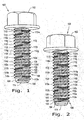
- numeral 100 designates a threaded fastener, and more specifically a bolt having a head 102, a shank 104 and a continuous helical thread 106 having a wave thread form.
- Helical thread 106 extends along a generally helical path on shank 104 and defines multiple thread pitches and convolutions, respectively, each thread pitch being a helical distance of one full rotation on shank 104.
- Helical thread 106 includes a lead-in thread portion 108 and both standard thread portions 110 and wave thread portions 112, as will be described in more detail hereinafter.
- Each wave thread portion 112 of the exemplary embodiment shown extends less than a full thread pitch and defines a thread segment in which the thread deviates from a straight line helical path.
- Each standard thread segment 110 of the exemplary embodiment shown extends for one full thread pitch and defines a thread segment extending along the generally straight line helical path.
- fastener 100 includes a blunt end or tip 114 on the end of shank 104 opposite head 102, but those skilled in the art will understand that a tapered end or tip also could be provided.
- thread 106 includes a pressure flank 120 and a trailing flank 122 from a thread crest 124 to a thread root 126.
- Thread 106 is disposed in a generally helical pattern along shank 104, and may extend substantially full length of fastener 100, or may begin or end some distance spaced from ends of the fastener.
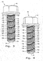
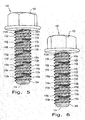
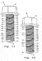
- FIG. 2 depicts fastener 100 rotated 30° from the view of the immediately preceding Fig. Accordingly, Fig. 2 depicts fastener 100 rotated 30° from the view of Fig. 1 ; Fig. 3 depicts fastener 100 rotated 30° from the view of Fig. 2 (and therefore 60° from the view of Fig. 1 ); Fig. 4 depicts fastener 100 rotated 30° from the view of Fig. 3 (and therefore 60° from the view of Fig. 2 and 90° from the view of Fig. 1 ); and so forth for the remaining Figs. 5-12 .
- Fig. 1 depicts fastener 100 rotated 30° from the view shown in Fig. 12 .
- head 102 is a six-sided shape configured for engagement by a wrench.
- head 102 can be otherwise configured than with a hexagonal shape.
- head 102 can be configured with a slot of cavity for receiving a screwdriver, torx driver, or driver of other type.
- the outer periphery of head 102 can be configured to engage drivers other than those for hex shapes.
- the wave thread form hereof uses individual waves which extend less than a full thread pitch, and in the exemplary embodiment for a distance of about 1/3 of a thread pitch (thus, 120° around shank 104), with each individual wave thread portion being separated from adjacent wave thread portions by a standard thread portion that extends for a distance of about one full thread pitch (thus, for 360° around shank 104). Accordingly, the wave thread portions are divided over multiple thread pitches and can extend in the pattern described for the full length of thread 104, or for some portion less than the full length of the thread, with a standard thread configuration at the beginning of the thread, at the end of the thread, or both.
- the individual wave thread portions are identified in consecutive manner by letters "a" through “m” along with the reference number 112. Accordingly beginning from lead-in thread portion 108, the first wave thread portion is designated as 112a, the next wave thread portion as 112b, and so forth. Similar designations have been applied to the standard thread portions 110 between the various wave thread portions 112a through 112m. A first standard thread portion between wave thread portion 112a and 112b has been identified as standard thread portion 110a, a second standard thread portion between wave thread portions 112b and 112c has been designated as standard thread portion 110b, and so forth along the length of fastener 100.
- Each wave thread portion 112a through 112m defines a thread segment that extends for one-third of a thread pitch and is separated from adjacent wave thread portions by a standard thread portion 110 that extends for a full thread pitch. Accordingly, the wave crests of adjacent wave thread portions 112a through 112m are separated by 1 1/3 thread pitch. Spreading the waves widens the stance of the fastener, creating a more stable and smooth interaction with the internal thread of a complementary female fastener component that will receive fastener 100. The prevailing torque benefits provided by wave threads are realized without the need to place the waves at exact points on the fastener, and without the need to position one of the fastener components within the other of the fastener components at a specific relative position.
- a first wave thread portion 112a may be preceded by a standard or lead in thread portion 108 of a suitable length, and the first wave thread portion 112a extends for 1/3 thread pitch or a distance of approximately 120° around shank 104.
- a standard helical thread portion 110a continues from first wave thread portion 112a and extends for a distance of one complete helix, 360° around shank 104 from the end of first wave thread portion 112a.
- a second wave thread portion 112b is provided extending for approximately a distance of 1/3 thread pitch (120° around shank 104), followed again by a standard thread portion 110b for a complete thread pitch, extending 360° around shank 104.
- a third wave thread portion 112c extends for a length covering approximately 120° around the shank. This pattern of wave thread portions extending approximately 120° around shank 104 (1/3 thread pitch) followed by a standard thread portion extending approximately 360° around the shank 104 (one full thread pitch) continues from the lead end tip of the fastener throughout the length of the thread.
- first, second and third wave thread portions can be appreciated from comparing the series of depictions of the fastener rotated by 30° increments from Fig. 1 through Fig. 12 .
- Fig. 1 the first wave thread portion 112a and the third wave thread portion 112c are visible, while the second wave thread portion 112b is not visible.
- the fastener is rotated 30° to the view of Fig. 2
- less of the third wave thread portion 112c is visible, and more of the first wave thread portion 112a is visible.
- the second wave thread portion 112b enters into the view. With an additional 30° rotation, as shown in Fig.
- the third wave thread portion 112c has been rotated out of view, and more of the second wave thread portion 112b can be seen.
- the first wave thread portion 112a remains visible.
- the continued progression can be seen throughout further rotations of the fastener from Fig. 5 through Fig. 12 .
- the relative positions of the other wave thread portions 112d-112m can also be appreciated from Figs. 1-12 .
- Thread 106 remains the same in cross-sectional shape throughout the standard thread portions 110 and the wave thread portions 112. Throughout the helical pattern, the cross-sectional shape remains the same. However, the entire thread from root 126 to crest 124 follows a curved path along the wave thread portions 112. In the exemplary embodiment shown, wave thread portions 112 deviate from the straight line path in the direction away from head 102 and toward tip 114; however, fasteners can be provided in which wave thread portions deviate from a straight-line path toward the head of the fastener and away from the tip of the fastener, or deviate from the straight-line path in both directions.
- wave thread portions 112 each define a single wave extending 1/3 of a thread pitch; however, it should be understood that wave thread portions having more than a single wave can be used, and/or wave thread portions can extend for distances more or less than 1/3 of a full thread pitch.
- the exemplary embodiment has been shown and described to include standard thread portions 110 between adjacent wave thread portions 112 in which the standard thread portions 110 extend for one complete pitch of the thread, adjacent wave thread portions can be separated by standard thread portions extending more or less than a full thread pitch.
- the desired cooperative relationship between male and female threads in a threaded assembly can be advantageously designed to take full advantage of the prevailing torque features provided by the wave thread portions when more or less than three thread pitches are engaged in the threaded assembly.
- the amplitude of each wave in the wave thread portions 112 can be selected to provide the desired prevailing torque characteristics, with higher amplitudes providing greater prevailing torque and lower amplitudes providing lower prevailing torque. Torque requirements can be precisely controlled through selection of amplitude and frequency of the waves in the wave thread portions 112 along with the spacing of the wave thread portions with standard thread portions 110 therebetween.
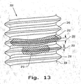
- Fastener 200 illustrated therein includes a shank 204, standard thread portions 210 and a wave thread portion 212 similar to the wave thread portions 112a-112m described previously herein.
- Wave thread portion 212 is paired with a nested wave thread portion 213 on the adjacent thread pitch.
- Wave thread portion 212 has a wave height indicated in Fig. 13 by the dimension designated 230, and nested wave thread portion 213 has a wave height indicated by the dimension designated 232.
- the nested wave thread portion 213 can have a wave height 232 less than the wave height 230 of its associated wave thread portion 212. Nested wave thread portions 213 having one-half the wave height of the associated wave thread portions 212 have worked effectively.
- Nested wave thread portion 213 can be generally axially aligned with the associated wave thread portion 212 on fastener shank 204, as shown in Fig. 13 , and in the exemplary embodiment deviates from the straight-line helical path in the same direction as the associated wave thread portion 212.
- wave thread portion 212 and nested wave thread portion 213 each deviate from the straight-line helical path any same direction, toward the tip of fastener 200.
- Use of the nested wave 213 facilitates thread rotation when fine threads are used and/or when one or the other of the threaded fastener components are of softer material, and/or are of small diameter.
- the nested wave 213 overcomes disadvantages that can result from root interference of the engaging threads under these and other conditions.
- the nested wave does not engage the internal thread in a fastened assembly, but provides additional clearance to the internal thread. In softer materials, the nested wave 213 allows material flow created by the full associated size wave portion 212.
Description
- The present invention relates generally to threaded fasteners, and, more specifically, the invention relates to thread configurations in threaded fasteners for creating prevailing torque in a threaded assembly, (see, for example,
US 3 661 194 A , corresponding to the preamble of claim 1). - Simple threaded fasteners include a male threaded component and a female threaded component configured to engage one with another. According to the Industrial Fasteners Institute (IFI), a thread is defined as a uniform section in the form of a helix on the external or internal surface of a cylinder. To improve the performance of threaded fasteners for different purposes, a variety of thread configurations are known. In general, threads of all types are based on a straight-line helix pattern. The thread pitch may vary from one type or size of fastener to another, and it is known to provide a differing thread pitch on different portions of the same fastener. However, regardless of the pitch the thread follows a straight-line helical pattern.
- In a standard fastener design, for a given or "basic" pitch, and convolution, respectively, the male thread is provided at equal to or less than the basic pitch and the female thread is provided at equal to or more than the basic pitch. The result is that the male thread "floats" within the female thread, allowing the two components to be run together throughout the thread length with little or no interference until clamping pressure is applied during final tightening of the fastener. As the fastener is tightened and clamp load applied, friction is created from stretch in the fastener as it is placed under tension. Clamp load can loosen from vibration, slip of the angular thread surfaces over time, expansion and contraction cycles and the like. It is known to provide prevailing torque by deforming the nut or using paste-like substances in the threads to maintain the relative position of the male and female components, even if clamp load is lost. Crimping a nut adds considerable cost to the manufacturing process, and known paste-like substances for the purpose are somewhat limited in extreme temperature conditions and have limited reusability.
- Further difficulties occur when threaded fasteners are used in somewhat non-standard situations. Tightening the fastener requires application of clamp load, meaning the head of the fastener, the confronting surface of the female fastener and all materials or components therebetween are compressed together. In so called "soft joints" such as, for example, joints holding together elastic materials, gaskets or the like, it is desirable that the fastener joint be tight without excessive clamp force applied on the material being held. Shoulder bolts or standard fasteners with spacers have been used for this purpose, complicating assembly and increasing costs.
- Threaded fasteners are known to be preassembled in components that are designed to be installed with other components or associated members, and thereafter tightened. For example, various electrical assemblies are provided for use in the field with screws already in place on terminals to receive wires therein. With the wire properly positioned, the screw is tightened to establish electrical connection between the wire and the electrical assembly. The pre-installed position of the screw must be relatively secure so that the screw does not become lost, making the component unusable.
- United States Patent
7,326,014 discloses an interactive fit screw thread that includes a curved line path thread provided within the helical thread pattern on the shank of a fastener. The curved thread pitch is provided to establish prevailing torque along desired portions of the fastener. Instead of the generally straight-line helical path followed by common fastener threads, the interactive fit screw disclosed in the '014 patent follows a curved-line path in a helical pattern. The exemplary embodiment disclosed in the '014 patent follows a sinusoidal wave path. - To assure aligned attachment with a mating thread, three wave periods covering 360° around the fastener shank are used in the embodiments disclosed in the aforementioned United States Patent
7,326,014 . Each wave crest is 120° from the previous wave crest, and the waves follow immediately after one another so that the waves are clustered on a single thread pitch. This works effectively; however, to achieve the advantages provided from the wave portions of the thread, the fastener is position dependent. In a threaded assembly, it is necessary to have the wave thread portion properly located with respect to the mating thread to ensure proper engagement and alignment of three waves. For example, it is common to provide four internal thread pitches in a female fastener component. To work most effectively, three waves of the male fastener component should be located in engagement with the threads of the female component. If the male fastener component is over rotated or under rotated relative to the female fastener component, so that less than three waves are engaged with the female component, the threaded assembly can be less effective. Accordingly, it has been necessary to have a coordinated knowledge of the final fastener component relationships so that the waves can be positioned appropriately for finally engagement in the female threaded component. - It is desirable to provide a threaded fastener having an interactive fit screw thread that is not position dependent and that provides prevailing torque along an elongated portion of the thread length.
- The invention is defined by the technical features set forth in
claim 1; further features of the invention are discloses in the dependent claims. - The wave thread form described herein provides fasteners with built in prevailing torque, the advantages of which can be experienced with random positioning of the fastener in a fastener assembly, by including both wave thread portions and standard thread portions along a generally helical thread. In a preferred form, each wave thread portion extends less than a full thread pitch and convolution, respectively, and is separated from adjacent wave thread portions by a standard thread portion extending for a full thread pitch.
- In one aspect of an embodiment thereof, a thread form for a threaded fastener having a thread extending along a generally helical path for multiple thread pitches is provided with multiple wave thread portions each defining a thread segment in which the thread deviates from a straight line helical path. A standard thread portion is provided between adjacent wave thread portions, each standard thread portion defining a thread segment extending along the generally straight line helical path.
- In one aspect of an embodiment thereof, a threaded fastener is provided with a shank and a thread on the shank, the thread defining multiple thread pitches along a generally helical path. The thread includes multiple wave thread portions each defining a thread segment in which the thread deviates from the straight line helical path, and a standard thread portion between adjacent wave thread portions, each standard thread portion defining a thread segment extending along the generally straight line helical path.
- An advantage of one embodiment of a wave thread form as described herein is providing a fastener with built-in prevailing torque along an extended length of the fastener, with which the advantages of prevailing torque can be realized with random positioning of the threaded fastener in a threaded assembly.
- Another advantage of an embodiment of a wave thread form as described herein is providing a fastener with built in that can be used efficiently in soft joints.
- Still another advantage provided by at least some embodiments of wave thread forms as described herein is providing threaded fasteners with built in prevailing torque that can be used for fasteners with fine thread configurations, fasteners of small diameter and/or fastener assemblies in which at least one threaded component is made of relatively soft material.
- Other features and advantages of the invention will become apparent to those skilled in the art upon review of the following detailed description, claims and drawings in which like numerals are used to designate like features.
-
-
Fig. 1 is a perspective view of a threaded fastener having a wave thread form as disclosed herein; -
Fig. 2 is a perspective view of the threaded fastener rotated 30° in a right-hand, or clockwise direction from the position shown inFig. 1 ; -
Fig. 3 is a perspective view of the threaded fastener rotated 30° in a right-hand, or clockwise direction from the position shown inFig. 2 ; -
Fig. 4 is a perspective view of the threaded fastener rotated 30° in a right-hand, or clockwise direction from the position shown inFig. 3 ; -
Fig. 5 is a perspective view of the threaded fastener rotated 30° in a right-hand, or clockwise direction from the position shown inFig. 4 ; -
Fig. 6 is a perspective view of the threaded fastener rotated 30° in a right-hand, or clockwise direction from the position shown inFig.5 ; -
Fig. 7 is a perspective view of the threaded fastener rotated 30° in a right-hand, or clockwise direction from the position shown inFig. 6 ; -
Fig. 8 is a perspective view of the threaded fastener rotated 30° in a right-hand, or clockwise direction from the position shown inFig. 7 ; -
Fig. 9 is a perspective view of the threaded fastener rotated 30° in a right-hand, or clockwise direction from the position shown inFig. 8 ; -
Fig. 10 is a perspective view of the threaded fastener rotated 30° in a right-hand, or clockwise direction from the position shown inFig. 9 ; -
Fig. 11 is a perspective view of the threaded fastener rotated 30° in a right-hand, or clockwise direction from the position shown inFig. 10 ; -
Fig. 12 is a perspective view of the threaded fastener rotated 30° in a right-hand, or clockwise direction from the position shown inFig. 11 ; and -
Fig. 13 is an enlarged, fragmentary view of an alternate form of a wave thread form. - Before the embodiments of the invention are explained in detail, it is to be understood that the invention is not limited in its application to the details of construction and the arrangements of the components set forth in the following description or illustrated in the drawings. The invention is capable of other embodiments and of being practiced or being carried out in various ways. Also, it is understood that the phraseology and terminology used herein are for the purpose of description and should not be regarded as limiting. The use herein of "including", "comprising" and variations thereof is meant to encompass the items listed thereafter and equivalents thereof, as well as additional items and equivalents thereof.
- Referring now more specifically to the drawings and to
Fig. 1 in particular, numeral 100 designates a threaded fastener, and more specifically a bolt having ahead 102, ashank 104 and a continuoushelical thread 106 having a wave thread form.Helical thread 106 extends along a generally helical path onshank 104 and defines multiple thread pitches and convolutions, respectively, each thread pitch being a helical distance of one full rotation onshank 104.Helical thread 106 includes a lead-inthread portion 108 and bothstandard thread portions 110 and wave thread portions 112, as will be described in more detail hereinafter. Each wave thread portion 112 of the exemplary embodiment shown extends less than a full thread pitch and defines a thread segment in which the thread deviates from a straight line helical path. Eachstandard thread segment 110 of the exemplary embodiment shown extends for one full thread pitch and defines a thread segment extending along the generally straight line helical path. In the exemplary embodiment shown,fastener 100 includes a blunt end or tip 114 on the end ofshank 104opposite head 102, but those skilled in the art will understand that a tapered end or tip also could be provided. - As shown in
Fig. 1 ,thread 106 includes a pressure flank 120 and a trailing flank 122 from athread crest 124 to athread root 126.Thread 106 is disposed in a generally helical pattern alongshank 104, and may extend substantially full length offastener 100, or may begin or end some distance spaced from ends of the fastener. -
Figs. 2-12 depictfastener 100 rotated 30° from the view of the immediately preceding Fig. Accordingly,Fig. 2 depictsfastener 100 rotated 30° from the view ofFig. 1 ;Fig. 3 depictsfastener 100 rotated 30° from the view ofFig. 2 (and therefore 60° from the view ofFig. 1 );Fig. 4 depictsfastener 100 rotated 30° from the view ofFig. 3 (and therefore 60° from the view ofFig. 2 and 90° from the view ofFig. 1 ); and so forth for the remainingFigs. 5-12 . Thus, it should also be noted thatFig. 1 depictsfastener 100 rotated 30° from the view shown inFig. 12 . - It should be understood that the specific fastener shown in the drawings is merely exemplary, and the wave thread form disclosed herein can be used on various types of fasteners including those having only limited threaded portions on extended length shanks, screw-type fasteners and threaded fasteners of other types. In the exemplary embodiment illustrated,
head 102 is a six-sided shape configured for engagement by a wrench. Those skilled in the art will readily understand thathead 102 can be otherwise configured than with a hexagonal shape. Thus,head 102 can be configured with a slot of cavity for receiving a screwdriver, torx driver, or driver of other type. Further, the outer periphery ofhead 102 can be configured to engage drivers other than those for hex shapes. - The wave thread form hereof uses individual waves which extend less than a full thread pitch, and in the exemplary embodiment for a distance of about 1/3 of a thread pitch (thus, 120° around shank 104), with each individual wave thread portion being separated from adjacent wave thread portions by a standard thread portion that extends for a distance of about one full thread pitch (thus, for 360° around shank 104). Accordingly, the wave thread portions are divided over multiple thread pitches and can extend in the pattern described for the full length of
thread 104, or for some portion less than the full length of the thread, with a standard thread configuration at the beginning of the thread, at the end of the thread, or both. - In the exemplary embodiment, the individual wave thread portions are identified in consecutive manner by letters "a" through "m" along with the reference number 112. Accordingly beginning from lead-in
thread portion 108, the first wave thread portion is designated as 112a, the next wave thread portion as 112b, and so forth. Similar designations have been applied to thestandard thread portions 110 between the variouswave thread portions 112a through 112m. A first standard thread portion betweenwave thread portion standard thread portion 110a, a second standard thread portion betweenwave thread portions standard thread portion 110b, and so forth along the length offastener 100. - Each
wave thread portion 112a through 112m defines a thread segment that extends for one-third of a thread pitch and is separated from adjacent wave thread portions by astandard thread portion 110 that extends for a full thread pitch. Accordingly, the wave crests of adjacentwave thread portions 112a through 112m are separated by 1 1/3 thread pitch. Spreading the waves widens the stance of the fastener, creating a more stable and smooth interaction with the internal thread of a complementary female fastener component that will receivefastener 100. The prevailing torque benefits provided by wave threads are realized without the need to place the waves at exact points on the fastener, and without the need to position one of the fastener components within the other of the fastener components at a specific relative position. Placing the waves on the external thread in the manner illustrated and described for the exemplary embodiment can perform effectively if any three pitches along the length of the fastener are engaged in the mating threaded structure. This allows the start of the thread to occur anywhere, without special consideration for the tooling and fastener with respect to the final assembly. So long as any three thread pitches are engaged, the appropriate number of wave thread portions will be involved in the final threaded assembly to achieve the full benefits of the prevailing torque provided from wave thread portions 112. - The pattern of the standard thread portions and wave thread portions on the helical thread now will be described more specifically with respect to
Figs. 1-12 . A firstwave thread portion 112a may be preceded by a standard or lead inthread portion 108 of a suitable length, and the firstwave thread portion 112a extends for 1/3 thread pitch or a distance of approximately 120° aroundshank 104. A standardhelical thread portion 110a continues from firstwave thread portion 112a and extends for a distance of one complete helix, 360° aroundshank 104 from the end of firstwave thread portion 112a. Thereafter a secondwave thread portion 112b is provided extending for approximately a distance of 1/3 thread pitch (120° around shank 104), followed again by astandard thread portion 110b for a complete thread pitch, extending 360° aroundshank 104. Thereafter a thirdwave thread portion 112c extends for a length covering approximately 120° around the shank. This pattern of wave thread portions extending approximately 120° around shank 104 (1/3 thread pitch) followed by a standard thread portion extending approximately 360° around the shank 104 (one full thread pitch) continues from the lead end tip of the fastener throughout the length of the thread. - The locations of the first, second and third wave thread portions can be appreciated from comparing the series of depictions of the fastener rotated by 30° increments from
Fig. 1 through Fig. 12 . InFig. 1 , the firstwave thread portion 112a and the thirdwave thread portion 112c are visible, while the secondwave thread portion 112b is not visible. When the fastener is rotated 30° to the view ofFig. 2 , less of the thirdwave thread portion 112c is visible, and more of the firstwave thread portion 112a is visible. When the fastener is rotated an additional 30° to the view ofFig. 3 , the secondwave thread portion 112b enters into the view. With an additional 30° rotation, as shown inFig. 4 , the thirdwave thread portion 112c has been rotated out of view, and more of the secondwave thread portion 112b can be seen. The firstwave thread portion 112a remains visible. The continued progression can be seen throughout further rotations of the fastener fromFig. 5 through Fig. 12 . The relative positions of the otherwave thread portions 112d-112m can also be appreciated fromFigs. 1-12 . -
Thread 106 remains the same in cross-sectional shape throughout thestandard thread portions 110 and the wave thread portions 112. Throughout the helical pattern, the cross-sectional shape remains the same. However, the entire thread fromroot 126 to crest 124 follows a curved path along the wave thread portions 112. In the exemplary embodiment shown, wave thread portions 112 deviate from the straight line path in the direction away fromhead 102 and towardtip 114; however, fasteners can be provided in which wave thread portions deviate from a straight-line path toward the head of the fastener and away from the tip of the fastener, or deviate from the straight-line path in both directions. - In the exemplary embodiment shown, wave thread portions 112 each define a single wave extending 1/3 of a thread pitch; however, it should be understood that wave thread portions having more than a single wave can be used, and/or wave thread portions can extend for distances more or less than 1/3 of a full thread pitch. Further, while the exemplary embodiment has been shown and described to include
standard thread portions 110 between adjacent wave thread portions 112 in which thestandard thread portions 110 extend for one complete pitch of the thread, adjacent wave thread portions can be separated by standard thread portions extending more or less than a full thread pitch. Thus, the desired cooperative relationship between male and female threads in a threaded assembly can be advantageously designed to take full advantage of the prevailing torque features provided by the wave thread portions when more or less than three thread pitches are engaged in the threaded assembly. Further, the amplitude of each wave in the wave thread portions 112 can be selected to provide the desired prevailing torque characteristics, with higher amplitudes providing greater prevailing torque and lower amplitudes providing lower prevailing torque. Torque requirements can be precisely controlled through selection of amplitude and frequency of the waves in the wave thread portions 112 along with the spacing of the wave thread portions withstandard thread portions 110 therebetween. - Another embodiment of the wave thread form is shown in
Fig. 13 .Fastener 200 illustrated therein includes ashank 204,standard thread portions 210 and awave thread portion 212 similar to thewave thread portions 112a-112m described previously herein.Wave thread portion 212 is paired with a nestedwave thread portion 213 on the adjacent thread pitch.Wave thread portion 212 has a wave height indicated inFig. 13 by the dimension designated 230, and nestedwave thread portion 213 has a wave height indicated by the dimension designated 232. The nestedwave thread portion 213 can have awave height 232 less than thewave height 230 of its associatedwave thread portion 212. Nestedwave thread portions 213 having one-half the wave height of the associatedwave thread portions 212 have worked effectively. Nestedwave thread portion 213 can be generally axially aligned with the associatedwave thread portion 212 onfastener shank 204, as shown inFig. 13 , and in the exemplary embodiment deviates from the straight-line helical path in the same direction as the associatedwave thread portion 212. In the exemplary embodiment,wave thread portion 212 and nestedwave thread portion 213 each deviate from the straight-line helical path any same direction, toward the tip offastener 200. Use of the nestedwave 213 facilitates thread rotation when fine threads are used and/or when one or the other of the threaded fastener components are of softer material, and/or are of small diameter. The nestedwave 213 overcomes disadvantages that can result from root interference of the engaging threads under these and other conditions. The nested wave does not engage the internal thread in a fastened assembly, but provides additional clearance to the internal thread. In softer materials, the nestedwave 213 allows material flow created by the full associatedsize wave portion 212. - Various features of the invention are set forth in the following claims, which define the scope of the invention.
Claims (15)
- A thread form for a threaded fastener (100) having a thread (106) extending along a generally helical path for multiple thread pitches, said thread form comprising:multiple wave thread portions (112; 212) each defining a thread segment in which the thread deviates from a straight line helical path; anda standard thread portion (110) defining a thread segment extending along a generally straight line helical path,characterized in thatthe standard thread portion (110) is defined between adjacent wave thread portions (112).
- The thread form of claim 1, each wave thread portion (112) extending for a distance less than a full thread pitch.
- The thread form of claim 1 or 2, each standard thread portion (110) extending a distance of at least a full thread pitch.
- The thread form of claim 1, each wave thread portion (112) extending for a distance of approximately one-third of a thread pitch and defining one complete wave deviating in one direction away from the straight line helical path; and each standard thread portion (110) extending for a distance of approximately one full thread pitch.
- The thread form of claim 4, including at least three said wave thread portions (112).
- The thread form of anyone of the preceding claims, each said wave thread portion (212) defining a wave of a first wave height (230), and said thread including a nested wave thread portion (213) defining a wave of a second wave height (232) less than said first wave height (230), said nested wave thread portion (213) being on a thread pitch adjacent to one of said wave thread portions (212) and deviating from the straight-line helical path in the same direction as said wave thread portions .
- The thread form of claim 6, said nested wave thread portion (213) being axially aligned with a wave thread portion (212) on an adjacent thread pitch.
- A threaded fastener comprising:a shank (104);a thread (106) on said shank (104) according to anyone of the preceding claims, said thread defining multiple thread pitches along a generally helical path.
- The threaded fastener of claim 8, each said wave thread portion (112; 212) extending for a distance less than a full thread pitch.
- The threaded fastener of claim 9, each said standard thread portion (110) between adjacent wave thread portions (112) extending for a distance of about one complete thread pitch.
- The threaded fastener of anyone of claims 8 to 10, each said wave thread portion (212) defining a wave of a first wave height (230), and said thread including a nested wave thread portion (213) defining a wave of a second wave height (232) less than said first wave height, said nested wave thread portion (213) being on a thread pitch adjacent to one of said wave thread portions (212) and deviating from the straight-line helical path in the same direction as said wave thread portions.
- The threaded fastener of claim 8, further including a head (102) at one end of said shank (106) and a distal tip (114) at an opposite end of said shank, and said wave thread portions (112; 212) each defining a single wave deviating from the straight-line helical path toward said distal tip of said shank.
- The threaded fastener of claim 12, each said wave thread portion (212) defining a wave of a first wave height (230), and said thread including a nested wave thread portion (213) defining a wave of a second wave height (232) less than said first wave height (230), said nested wave thread portion (213) being on a thread pitch adjacent to one of said wave thread portions and a deviating from the straight-line helical path toward said distal tip (114) of said shank (106).
- The threaded fastener of anyone of claims 11 to 13, each said nested wave thread portion (213) being axially aligned with a wave thread portion (212) on an adjacent thread pitch.
- The threaded fastener of claim 14, said the second wave height (232) being approximately one-half said first wave height (230).
Applications Claiming Priority (2)
| Application Number | Priority Date | Filing Date | Title |
|---|---|---|---|
| US30870310P | 2010-02-26 | 2010-02-26 | |
| PCT/US2011/026170 WO2011106596A1 (en) | 2010-02-26 | 2011-02-25 | Wave thread form |
Publications (2)
| Publication Number | Publication Date |
|---|---|
| EP2539595A1 EP2539595A1 (en) | 2013-01-02 |
| EP2539595B1 true EP2539595B1 (en) | 2014-04-09 |
Family
ID=43923636
Family Applications (1)
| Application Number | Title | Priority Date | Filing Date |
|---|---|---|---|
| EP11707300.7A Active EP2539595B1 (en) | 2010-02-26 | 2011-02-25 | Wave thread form |
Country Status (5)
| Country | Link |
|---|---|
| US (1) | US9121430B2 (en) |
| EP (1) | EP2539595B1 (en) |
| JP (2) | JP2013521441A (en) |
| CN (1) | CN102770672B (en) |
| WO (1) | WO2011106596A1 (en) |
Families Citing this family (10)
| Publication number | Priority date | Publication date | Assignee | Title |
|---|---|---|---|---|
| EP2558275B1 (en) | 2010-04-16 | 2014-06-11 | Illinois Tool Works Inc. | Embeddable insert |
| RU2567353C1 (en) * | 2014-07-11 | 2015-11-10 | Федеральное государственное бюджетное образовательное учреждение высшего профессионального образования "Забайкальский государственный университет" (ФГБОУ ВПО "ЗабГУ") | Vibration-proof threaded connection (versions) |
| USD764267S1 (en) * | 2015-07-07 | 2016-08-23 | Physical Systems, Inc. | Hollow screw |
| JP5974196B1 (en) * | 2016-03-02 | 2016-08-23 | 甚太 芹澤 | Screw member, fastening member and dart |
| US20180051737A1 (en) * | 2016-08-18 | 2018-02-22 | Research Engineering & Manufacturing Inc. | High performance thread rolling and thread locking fastener |
| TWI705202B (en) * | 2016-11-28 | 2020-09-21 | 日商轉造技術研究所股份有限公司 | Double screw structure |
| CA3082258A1 (en) * | 2017-11-14 | 2019-05-23 | Penn Engineering & Manufacturing Corp. | Press-in fastener with a wavy knurled shank |
| USD899914S1 (en) * | 2018-11-21 | 2020-10-27 | Glen Haydn Pring | Fastener for a nut |
| KR102162007B1 (en) * | 2019-03-26 | 2020-10-06 | 동의대학교 산학협력단 | Pressure reducing valve with easy application pressure control |
| CN112756712B (en) * | 2019-10-21 | 2022-04-22 | 贵州捷盛钻具股份有限公司 | Method for machining tool withdrawal groove-free blind hole wave-shaped threads by using numerical control lathe |
Family Cites Families (25)
| Publication number | Priority date | Publication date | Assignee | Title |
|---|---|---|---|---|
| US756269A (en) * | 1903-01-05 | 1904-04-05 | John F Fromm | Nut-lock. |
| US1070247A (en) * | 1910-07-09 | 1913-08-12 | Frank P Haines | Self-locking screw. |
| US2349592A (en) * | 1940-04-22 | 1944-05-23 | Illinois Tool Works | Self-locking screw device |
| US3459250A (en) * | 1967-04-14 | 1969-08-05 | Burdsall Russell & Ward Bolt & | Prevailing-torque lockscrews |
| US3481380A (en) | 1967-05-18 | 1969-12-02 | Lamson & Sessions Co | Thread forming fastener |
| US3661194A (en) | 1970-01-02 | 1972-05-09 | Standard Pressed Steel Co | Prevailing torque fastener |
| US3885613A (en) * | 1970-11-09 | 1975-05-27 | Robert J Evans | Self-locking fastener |
| US3721283A (en) * | 1970-11-09 | 1973-03-20 | R Evans | Self-locking fastener |
| US3927503A (en) * | 1973-12-26 | 1975-12-23 | Standard Pressed Steel Co | Prevailing torque fastener |
| GB1478951A (en) * | 1975-04-17 | 1977-07-06 | Richards Fasteners Ltd C | Self-locking screw threads |
| JPH0284012U (en) * | 1988-12-19 | 1990-06-29 | ||
| JPH0331085A (en) | 1989-06-28 | 1991-02-08 | Suzuki Motor Corp | Front/rear-wheel-drive motorcycle |
| US5194214A (en) * | 1991-05-13 | 1993-03-16 | Westinghouse Electric Corp. | Tube plug and method for plugging a tube |
| JP3031085B2 (en) | 1992-11-05 | 2000-04-10 | 松下電器産業株式会社 | Seesaw-operated electronic components |
| JP3031085U (en) * | 1996-05-10 | 1996-11-12 | ユルソン株式会社 | bolt |
| US6464439B1 (en) * | 1997-08-04 | 2002-10-15 | Bernhard M. Janitzki | Low tolerance threaded fastener |
| DE202004002877U1 (en) | 2004-02-25 | 2005-06-30 | A-Z Ausrüstung Und Zubehör Gmbh & Co. Kg | Thread forming screw |
| CN100523527C (en) * | 2004-04-21 | 2009-08-05 | 伊利诺斯器械工程公司 | Threaded fastener |
| US7326014B2 (en) | 2004-04-21 | 2008-02-05 | Illinois Tool Works, Inc | Interactive fit screw thread |
| DE102004053803B4 (en) | 2004-11-08 | 2006-10-26 | Hilti Ag | Thread-forming screw |
| US20070274805A1 (en) * | 2006-05-26 | 2007-11-29 | Nebl David R | Fastener and assembly therewith |
| US20090003969A1 (en) * | 2007-06-29 | 2009-01-01 | Gattone Michael T | Linear adjustment assembly |
| US7914244B2 (en) * | 2007-10-03 | 2011-03-29 | Illinois Tool Works Inc. | Fastener with zoned, varying wave-form thread |
| US7963732B2 (en) * | 2008-04-24 | 2011-06-21 | Triangle Fastener Corporation | Threaded fastener |
| US8033700B2 (en) * | 2008-05-02 | 2011-10-11 | Asyst Technologies L.L.C. | Travel limiting headlamp adjuster |
-
2011
- 2011-02-25 CN CN201180011254.8A patent/CN102770672B/en active Active
- 2011-02-25 US US13/580,768 patent/US9121430B2/en active Active
- 2011-02-25 JP JP2012555169A patent/JP2013521441A/en active Pending
- 2011-02-25 EP EP11707300.7A patent/EP2539595B1/en active Active
- 2011-02-25 WO PCT/US2011/026170 patent/WO2011106596A1/en active Application Filing
-
2015
- 2015-10-30 JP JP2015005559U patent/JP3203399U/en not_active Expired - Lifetime
Also Published As
| Publication number | Publication date |
|---|---|
| EP2539595A1 (en) | 2013-01-02 |
| WO2011106596A1 (en) | 2011-09-01 |
| CN102770672A (en) | 2012-11-07 |
| US9121430B2 (en) | 2015-09-01 |
| US20120315110A1 (en) | 2012-12-13 |
| JP3203399U (en) | 2016-03-31 |
| JP2013521441A (en) | 2013-06-10 |
| CN102770672B (en) | 2014-12-31 |
Similar Documents
| Publication | Publication Date | Title |
|---|---|---|
| EP2539595B1 (en) | Wave thread form | |
| EP1738086B1 (en) | Threaded fastener | |
| US4181457A (en) | Tapping tool for making vibration resistant prevailing torque fastener | |
| US4150702A (en) | Locking fastener | |
| US3481380A (en) | Thread forming fastener | |
| US4396321A (en) | Tapping tool for making vibration resistant prevailing torque fastener | |
| US7914244B2 (en) | Fastener with zoned, varying wave-form thread | |
| US5636956A (en) | Fastener and screw means therefor | |
| US10233963B2 (en) | Deformable fastening thread providing wedge-effect | |
| US20210364029A1 (en) | Threaded fastener having a thread crest greater than its thread root and v angles on the crest and root | |
| US6669424B1 (en) | Screwed connection, fastener for said connection and method for the production thereof | |
| CN214007738U (en) | Anti-loosening fastening assembly | |
| US4013110A (en) | Locking thread | |
| USRE31284E (en) | Locking fastener | |
| JP3031085U (en) | bolt | |
| JP6871595B2 (en) | Double screw construction | |
| EP3339665A1 (en) | Male threaded fastener | |
| JP6485685B2 (en) | Female thread body | |
| JPH0231606Y2 (en) | ||
| CN215950098U (en) | Nut, bolt and threaded connection structure | |
| JPH0135054Y2 (en) | ||
| KR102112168B1 (en) | Bolt for earth | |
| JPH0336798Y2 (en) | ||
| CN113309780A (en) | Nut, bolt and threaded connection structure |
Legal Events
| Date | Code | Title | Description |
|---|---|---|---|
| PUAI | Public reference made under article 153(3) epc to a published international application that has entered the european phase |
Free format text: ORIGINAL CODE: 0009012 |
|
| 17P | Request for examination filed |
Effective date: 20120822 |
|
| AK | Designated contracting states |
Kind code of ref document: A1 Designated state(s): AL AT BE BG CH CY CZ DE DK EE ES FI FR GB GR HR HU IE IS IT LI LT LU LV MC MK MT NL NO PL PT RO RS SE SI SK SM TR |
|
| DAX | Request for extension of the european patent (deleted) | ||
| GRAP | Despatch of communication of intention to grant a patent |
Free format text: ORIGINAL CODE: EPIDOSNIGR1 |
|
| INTG | Intention to grant announced |
Effective date: 20131002 |
|
| GRAS | Grant fee paid |
Free format text: ORIGINAL CODE: EPIDOSNIGR3 |
|
| GRAA | (expected) grant |
Free format text: ORIGINAL CODE: 0009210 |
|
| AK | Designated contracting states |
Kind code of ref document: B1 Designated state(s): AL AT BE BG CH CY CZ DE DK EE ES FI FR GB GR HR HU IE IS IT LI LT LU LV MC MK MT NL NO PL PT RO RS SE SI SK SM TR |
|
| REG | Reference to a national code |
Ref country code: GB Ref legal event code: FG4D |
|
| REG | Reference to a national code |
Ref country code: CH Ref legal event code: EP Ref country code: AT Ref legal event code: REF Ref document number: 661504 Country of ref document: AT Kind code of ref document: T Effective date: 20140415 |
|
| RAP2 | Party data changed (patent owner data changed or rights of a patent transferred) |
Owner name: ILLINOIS TOOL WORKS INC. |
|
| REG | Reference to a national code |
Ref country code: IE Ref legal event code: FG4D |
|
| REG | Reference to a national code |
Ref country code: DE Ref legal event code: R096 Ref document number: 602011006047 Country of ref document: DE Effective date: 20140522 |
|
| REG | Reference to a national code |
Ref country code: AT Ref legal event code: MK05 Ref document number: 661504 Country of ref document: AT Kind code of ref document: T Effective date: 20140409 |
|
| REG | Reference to a national code |
Ref country code: NL Ref legal event code: VDEP Effective date: 20140409 |
|
| REG | Reference to a national code |
Ref country code: LT Ref legal event code: MG4D |
|
| PG25 | Lapsed in a contracting state [announced via postgrant information from national office to epo] |
Ref country code: IS Free format text: LAPSE BECAUSE OF FAILURE TO SUBMIT A TRANSLATION OF THE DESCRIPTION OR TO PAY THE FEE WITHIN THE PRESCRIBED TIME-LIMIT Effective date: 20140809 Ref country code: FI Free format text: LAPSE BECAUSE OF FAILURE TO SUBMIT A TRANSLATION OF THE DESCRIPTION OR TO PAY THE FEE WITHIN THE PRESCRIBED TIME-LIMIT Effective date: 20140409 Ref country code: LT Free format text: LAPSE BECAUSE OF FAILURE TO SUBMIT A TRANSLATION OF THE DESCRIPTION OR TO PAY THE FEE WITHIN THE PRESCRIBED TIME-LIMIT Effective date: 20140409 Ref country code: NL Free format text: LAPSE BECAUSE OF FAILURE TO SUBMIT A TRANSLATION OF THE DESCRIPTION OR TO PAY THE FEE WITHIN THE PRESCRIBED TIME-LIMIT Effective date: 20140409 Ref country code: NO Free format text: LAPSE BECAUSE OF FAILURE TO SUBMIT A TRANSLATION OF THE DESCRIPTION OR TO PAY THE FEE WITHIN THE PRESCRIBED TIME-LIMIT Effective date: 20140709 Ref country code: BG Free format text: LAPSE BECAUSE OF FAILURE TO SUBMIT A TRANSLATION OF THE DESCRIPTION OR TO PAY THE FEE WITHIN THE PRESCRIBED TIME-LIMIT Effective date: 20140709 Ref country code: GR Free format text: LAPSE BECAUSE OF FAILURE TO SUBMIT A TRANSLATION OF THE DESCRIPTION OR TO PAY THE FEE WITHIN THE PRESCRIBED TIME-LIMIT Effective date: 20140710 |
|
| PG25 | Lapsed in a contracting state [announced via postgrant information from national office to epo] |
Ref country code: PL Free format text: LAPSE BECAUSE OF FAILURE TO SUBMIT A TRANSLATION OF THE DESCRIPTION OR TO PAY THE FEE WITHIN THE PRESCRIBED TIME-LIMIT Effective date: 20140409 Ref country code: ES Free format text: LAPSE BECAUSE OF FAILURE TO SUBMIT A TRANSLATION OF THE DESCRIPTION OR TO PAY THE FEE WITHIN THE PRESCRIBED TIME-LIMIT Effective date: 20140409 Ref country code: AT Free format text: LAPSE BECAUSE OF FAILURE TO SUBMIT A TRANSLATION OF THE DESCRIPTION OR TO PAY THE FEE WITHIN THE PRESCRIBED TIME-LIMIT Effective date: 20140409 Ref country code: LV Free format text: LAPSE BECAUSE OF FAILURE TO SUBMIT A TRANSLATION OF THE DESCRIPTION OR TO PAY THE FEE WITHIN THE PRESCRIBED TIME-LIMIT Effective date: 20140409 Ref country code: HR Free format text: LAPSE BECAUSE OF FAILURE TO SUBMIT A TRANSLATION OF THE DESCRIPTION OR TO PAY THE FEE WITHIN THE PRESCRIBED TIME-LIMIT Effective date: 20140409 Ref country code: RS Free format text: LAPSE BECAUSE OF FAILURE TO SUBMIT A TRANSLATION OF THE DESCRIPTION OR TO PAY THE FEE WITHIN THE PRESCRIBED TIME-LIMIT Effective date: 20140409 Ref country code: SE Free format text: LAPSE BECAUSE OF FAILURE TO SUBMIT A TRANSLATION OF THE DESCRIPTION OR TO PAY THE FEE WITHIN THE PRESCRIBED TIME-LIMIT Effective date: 20140409 |
|
| PG25 | Lapsed in a contracting state [announced via postgrant information from national office to epo] |
Ref country code: PT Free format text: LAPSE BECAUSE OF FAILURE TO SUBMIT A TRANSLATION OF THE DESCRIPTION OR TO PAY THE FEE WITHIN THE PRESCRIBED TIME-LIMIT Effective date: 20140811 |
|
| REG | Reference to a national code |
Ref country code: DE Ref legal event code: R097 Ref document number: 602011006047 Country of ref document: DE |
|
| PG25 | Lapsed in a contracting state [announced via postgrant information from national office to epo] |
Ref country code: BE Free format text: LAPSE BECAUSE OF FAILURE TO SUBMIT A TRANSLATION OF THE DESCRIPTION OR TO PAY THE FEE WITHIN THE PRESCRIBED TIME-LIMIT Effective date: 20140409 Ref country code: DK Free format text: LAPSE BECAUSE OF FAILURE TO SUBMIT A TRANSLATION OF THE DESCRIPTION OR TO PAY THE FEE WITHIN THE PRESCRIBED TIME-LIMIT Effective date: 20140409 Ref country code: CZ Free format text: LAPSE BECAUSE OF FAILURE TO SUBMIT A TRANSLATION OF THE DESCRIPTION OR TO PAY THE FEE WITHIN THE PRESCRIBED TIME-LIMIT Effective date: 20140409 Ref country code: SK Free format text: LAPSE BECAUSE OF FAILURE TO SUBMIT A TRANSLATION OF THE DESCRIPTION OR TO PAY THE FEE WITHIN THE PRESCRIBED TIME-LIMIT Effective date: 20140409 Ref country code: RO Free format text: LAPSE BECAUSE OF FAILURE TO SUBMIT A TRANSLATION OF THE DESCRIPTION OR TO PAY THE FEE WITHIN THE PRESCRIBED TIME-LIMIT Effective date: 20140409 Ref country code: EE Free format text: LAPSE BECAUSE OF FAILURE TO SUBMIT A TRANSLATION OF THE DESCRIPTION OR TO PAY THE FEE WITHIN THE PRESCRIBED TIME-LIMIT Effective date: 20140409 |
|
| PLBE | No opposition filed within time limit |
Free format text: ORIGINAL CODE: 0009261 |
|
| STAA | Information on the status of an ep patent application or granted ep patent |
Free format text: STATUS: NO OPPOSITION FILED WITHIN TIME LIMIT |
|
| 26N | No opposition filed |
Effective date: 20150112 |
|
| PG25 | Lapsed in a contracting state [announced via postgrant information from national office to epo] |
Ref country code: IT Free format text: LAPSE BECAUSE OF FAILURE TO SUBMIT A TRANSLATION OF THE DESCRIPTION OR TO PAY THE FEE WITHIN THE PRESCRIBED TIME-LIMIT Effective date: 20140409 |
|
| REG | Reference to a national code |
Ref country code: DE Ref legal event code: R097 Ref document number: 602011006047 Country of ref document: DE Effective date: 20150112 |
|
| PG25 | Lapsed in a contracting state [announced via postgrant information from national office to epo] |
Ref country code: SI Free format text: LAPSE BECAUSE OF FAILURE TO SUBMIT A TRANSLATION OF THE DESCRIPTION OR TO PAY THE FEE WITHIN THE PRESCRIBED TIME-LIMIT Effective date: 20140409 |
|
| PG25 | Lapsed in a contracting state [announced via postgrant information from national office to epo] |
Ref country code: LU Free format text: LAPSE BECAUSE OF FAILURE TO SUBMIT A TRANSLATION OF THE DESCRIPTION OR TO PAY THE FEE WITHIN THE PRESCRIBED TIME-LIMIT Effective date: 20150225 |
|
| REG | Reference to a national code |
Ref country code: CH Ref legal event code: PL |
|
| PG25 | Lapsed in a contracting state [announced via postgrant information from national office to epo] |
Ref country code: LI Free format text: LAPSE BECAUSE OF NON-PAYMENT OF DUE FEES Effective date: 20150228 Ref country code: CH Free format text: LAPSE BECAUSE OF NON-PAYMENT OF DUE FEES Effective date: 20150228 Ref country code: MC Free format text: LAPSE BECAUSE OF FAILURE TO SUBMIT A TRANSLATION OF THE DESCRIPTION OR TO PAY THE FEE WITHIN THE PRESCRIBED TIME-LIMIT Effective date: 20140409 |
|
| REG | Reference to a national code |
Ref country code: IE Ref legal event code: MM4A |
|
| PG25 | Lapsed in a contracting state [announced via postgrant information from national office to epo] |
Ref country code: IE Free format text: LAPSE BECAUSE OF NON-PAYMENT OF DUE FEES Effective date: 20150225 |
|
| REG | Reference to a national code |
Ref country code: FR Ref legal event code: PLFP Year of fee payment: 6 |
|
| PG25 | Lapsed in a contracting state [announced via postgrant information from national office to epo] |
Ref country code: MT Free format text: LAPSE BECAUSE OF FAILURE TO SUBMIT A TRANSLATION OF THE DESCRIPTION OR TO PAY THE FEE WITHIN THE PRESCRIBED TIME-LIMIT Effective date: 20140409 |
|
| REG | Reference to a national code |
Ref country code: FR Ref legal event code: PLFP Year of fee payment: 7 |
|
| PG25 | Lapsed in a contracting state [announced via postgrant information from national office to epo] |
Ref country code: SM Free format text: LAPSE BECAUSE OF FAILURE TO SUBMIT A TRANSLATION OF THE DESCRIPTION OR TO PAY THE FEE WITHIN THE PRESCRIBED TIME-LIMIT Effective date: 20140409 Ref country code: HU Free format text: LAPSE BECAUSE OF FAILURE TO SUBMIT A TRANSLATION OF THE DESCRIPTION OR TO PAY THE FEE WITHIN THE PRESCRIBED TIME-LIMIT; INVALID AB INITIO Effective date: 20110225 |
|
| PG25 | Lapsed in a contracting state [announced via postgrant information from national office to epo] |
Ref country code: CY Free format text: LAPSE BECAUSE OF FAILURE TO SUBMIT A TRANSLATION OF THE DESCRIPTION OR TO PAY THE FEE WITHIN THE PRESCRIBED TIME-LIMIT Effective date: 20140409 |
|
| PG25 | Lapsed in a contracting state [announced via postgrant information from national office to epo] |
Ref country code: TR Free format text: LAPSE BECAUSE OF FAILURE TO SUBMIT A TRANSLATION OF THE DESCRIPTION OR TO PAY THE FEE WITHIN THE PRESCRIBED TIME-LIMIT Effective date: 20140409 |
|
| REG | Reference to a national code |
Ref country code: FR Ref legal event code: PLFP Year of fee payment: 8 |
|
| PG25 | Lapsed in a contracting state [announced via postgrant information from national office to epo] |
Ref country code: MK Free format text: LAPSE BECAUSE OF FAILURE TO SUBMIT A TRANSLATION OF THE DESCRIPTION OR TO PAY THE FEE WITHIN THE PRESCRIBED TIME-LIMIT Effective date: 20140409 |
|
| PG25 | Lapsed in a contracting state [announced via postgrant information from national office to epo] |
Ref country code: AL Free format text: LAPSE BECAUSE OF FAILURE TO SUBMIT A TRANSLATION OF THE DESCRIPTION OR TO PAY THE FEE WITHIN THE PRESCRIBED TIME-LIMIT Effective date: 20140409 |
|
| PGFP | Annual fee paid to national office [announced via postgrant information from national office to epo] |
Ref country code: FR Payment date: 20230223 Year of fee payment: 13 |
|
| PGFP | Annual fee paid to national office [announced via postgrant information from national office to epo] |
Ref country code: GB Payment date: 20230227 Year of fee payment: 13 Ref country code: DE Payment date: 20230223 Year of fee payment: 13 |
|
| P01 | Opt-out of the competence of the unified patent court (upc) registered |
Effective date: 20230606 |