EP2538469B1 - Battery pack - Google Patents
Battery pack Download PDFInfo
- Publication number
- EP2538469B1 EP2538469B1 EP12159294.3A EP12159294A EP2538469B1 EP 2538469 B1 EP2538469 B1 EP 2538469B1 EP 12159294 A EP12159294 A EP 12159294A EP 2538469 B1 EP2538469 B1 EP 2538469B1
- Authority
- EP
- European Patent Office
- Prior art keywords
- rib
- battery
- bus bar
- battery pack
- pack according
- Prior art date
- Legal status (The legal status is an assumption and is not a legal conclusion. Google has not performed a legal analysis and makes no representation as to the accuracy of the status listed.)
- Active
Links
- 238000009413 insulation Methods 0.000 claims description 55
- RMPWIIKNWPVWNG-UHFFFAOYSA-N 1,2,3,4-tetrachloro-5-(2,3,4-trichlorophenyl)benzene Chemical compound ClC1=C(Cl)C(Cl)=CC=C1C1=CC(Cl)=C(Cl)C(Cl)=C1Cl RMPWIIKNWPVWNG-UHFFFAOYSA-N 0.000 description 30
- 230000008878 coupling Effects 0.000 description 27
- 238000010168 coupling process Methods 0.000 description 27
- 238000005859 coupling reaction Methods 0.000 description 27
- PXHVJJICTQNCMI-UHFFFAOYSA-N Nickel Chemical compound [Ni] PXHVJJICTQNCMI-UHFFFAOYSA-N 0.000 description 9
- 239000000470 constituent Substances 0.000 description 7
- 239000010949 copper Substances 0.000 description 6
- RYGMFSIKBFXOCR-UHFFFAOYSA-N Copper Chemical compound [Cu] RYGMFSIKBFXOCR-UHFFFAOYSA-N 0.000 description 3
- 239000004411 aluminium Substances 0.000 description 3
- 229910052782 aluminium Inorganic materials 0.000 description 3
- XAGFODPZIPBFFR-UHFFFAOYSA-N aluminium Chemical compound [Al] XAGFODPZIPBFFR-UHFFFAOYSA-N 0.000 description 3
- 229910052802 copper Inorganic materials 0.000 description 3
- 230000001747 exhibiting effect Effects 0.000 description 3
- 239000007769 metal material Substances 0.000 description 3
- 229910052759 nickel Inorganic materials 0.000 description 3
- 239000012774 insulation material Substances 0.000 description 2
- 239000000463 material Substances 0.000 description 2
- 125000006850 spacer group Chemical group 0.000 description 2
- HBBGRARXTFLTSG-UHFFFAOYSA-N Lithium ion Chemical compound [Li+] HBBGRARXTFLTSG-UHFFFAOYSA-N 0.000 description 1
- 229920000265 Polyparaphenylene Polymers 0.000 description 1
- UCKMPCXJQFINFW-UHFFFAOYSA-N Sulphide Chemical compound [S-2] UCKMPCXJQFINFW-UHFFFAOYSA-N 0.000 description 1
- 230000004308 accommodation Effects 0.000 description 1
- 238000005452 bending Methods 0.000 description 1
- 239000004020 conductor Substances 0.000 description 1
- 238000004146 energy storage Methods 0.000 description 1
- 238000010304 firing Methods 0.000 description 1
- 238000010438 heat treatment Methods 0.000 description 1
- 229910001416 lithium ion Inorganic materials 0.000 description 1
- 239000002952 polymeric resin Substances 0.000 description 1
- -1 polyphenylene Polymers 0.000 description 1
- 238000000926 separation method Methods 0.000 description 1
- 229920003002 synthetic resin Polymers 0.000 description 1
Images


Classifications
-
- H—ELECTRICITY
- H01—ELECTRIC ELEMENTS
- H01M—PROCESSES OR MEANS, e.g. BATTERIES, FOR THE DIRECT CONVERSION OF CHEMICAL ENERGY INTO ELECTRICAL ENERGY
- H01M10/00—Secondary cells; Manufacture thereof
- H01M10/42—Methods or arrangements for servicing or maintenance of secondary cells or secondary half-cells
- H01M10/425—Structural combination with electronic components, e.g. electronic circuits integrated to the outside of the casing
-
- H—ELECTRICITY
- H01—ELECTRIC ELEMENTS
- H01M—PROCESSES OR MEANS, e.g. BATTERIES, FOR THE DIRECT CONVERSION OF CHEMICAL ENERGY INTO ELECTRICAL ENERGY
- H01M50/00—Constructional details or processes of manufacture of the non-active parts of electrochemical cells other than fuel cells, e.g. hybrid cells
- H01M50/50—Current conducting connections for cells or batteries
- H01M50/502—Interconnectors for connecting terminals of adjacent batteries; Interconnectors for connecting cells outside a battery casing
-
- H—ELECTRICITY
- H01—ELECTRIC ELEMENTS
- H01M—PROCESSES OR MEANS, e.g. BATTERIES, FOR THE DIRECT CONVERSION OF CHEMICAL ENERGY INTO ELECTRICAL ENERGY
- H01M10/00—Secondary cells; Manufacture thereof
- H01M10/04—Construction or manufacture in general
- H01M10/0413—Large-sized flat cells or batteries for motive or stationary systems with plate-like electrodes
-
- H—ELECTRICITY
- H01—ELECTRIC ELEMENTS
- H01M—PROCESSES OR MEANS, e.g. BATTERIES, FOR THE DIRECT CONVERSION OF CHEMICAL ENERGY INTO ELECTRICAL ENERGY
- H01M10/00—Secondary cells; Manufacture thereof
- H01M10/04—Construction or manufacture in general
- H01M10/0436—Small-sized flat cells or batteries for portable equipment
-
- H—ELECTRICITY
- H01—ELECTRIC ELEMENTS
- H01M—PROCESSES OR MEANS, e.g. BATTERIES, FOR THE DIRECT CONVERSION OF CHEMICAL ENERGY INTO ELECTRICAL ENERGY
- H01M50/00—Constructional details or processes of manufacture of the non-active parts of electrochemical cells other than fuel cells, e.g. hybrid cells
- H01M50/20—Mountings; Secondary casings or frames; Racks, modules or packs; Suspension devices; Shock absorbers; Transport or carrying devices; Holders
- H01M50/204—Racks, modules or packs for multiple batteries or multiple cells
- H01M50/207—Racks, modules or packs for multiple batteries or multiple cells characterised by their shape
- H01M50/209—Racks, modules or packs for multiple batteries or multiple cells characterised by their shape adapted for prismatic or rectangular cells
-
- H—ELECTRICITY
- H01—ELECTRIC ELEMENTS
- H01M—PROCESSES OR MEANS, e.g. BATTERIES, FOR THE DIRECT CONVERSION OF CHEMICAL ENERGY INTO ELECTRICAL ENERGY
- H01M50/00—Constructional details or processes of manufacture of the non-active parts of electrochemical cells other than fuel cells, e.g. hybrid cells
- H01M50/20—Mountings; Secondary casings or frames; Racks, modules or packs; Suspension devices; Shock absorbers; Transport or carrying devices; Holders
- H01M50/284—Mountings; Secondary casings or frames; Racks, modules or packs; Suspension devices; Shock absorbers; Transport or carrying devices; Holders with incorporated circuit boards, e.g. printed circuit boards [PCB]
-
- H—ELECTRICITY
- H01—ELECTRIC ELEMENTS
- H01M—PROCESSES OR MEANS, e.g. BATTERIES, FOR THE DIRECT CONVERSION OF CHEMICAL ENERGY INTO ELECTRICAL ENERGY
- H01M50/00—Constructional details or processes of manufacture of the non-active parts of electrochemical cells other than fuel cells, e.g. hybrid cells
- H01M50/20—Mountings; Secondary casings or frames; Racks, modules or packs; Suspension devices; Shock absorbers; Transport or carrying devices; Holders
- H01M50/289—Mountings; Secondary casings or frames; Racks, modules or packs; Suspension devices; Shock absorbers; Transport or carrying devices; Holders characterised by spacing elements or positioning means within frames, racks or packs
- H01M50/291—Mountings; Secondary casings or frames; Racks, modules or packs; Suspension devices; Shock absorbers; Transport or carrying devices; Holders characterised by spacing elements or positioning means within frames, racks or packs characterised by their shape
-
- H—ELECTRICITY
- H01—ELECTRIC ELEMENTS
- H01M—PROCESSES OR MEANS, e.g. BATTERIES, FOR THE DIRECT CONVERSION OF CHEMICAL ENERGY INTO ELECTRICAL ENERGY
- H01M50/00—Constructional details or processes of manufacture of the non-active parts of electrochemical cells other than fuel cells, e.g. hybrid cells
- H01M50/20—Mountings; Secondary casings or frames; Racks, modules or packs; Suspension devices; Shock absorbers; Transport or carrying devices; Holders
- H01M50/296—Mountings; Secondary casings or frames; Racks, modules or packs; Suspension devices; Shock absorbers; Transport or carrying devices; Holders characterised by terminals of battery packs
-
- H—ELECTRICITY
- H01—ELECTRIC ELEMENTS
- H01M—PROCESSES OR MEANS, e.g. BATTERIES, FOR THE DIRECT CONVERSION OF CHEMICAL ENERGY INTO ELECTRICAL ENERGY
- H01M50/00—Constructional details or processes of manufacture of the non-active parts of electrochemical cells other than fuel cells, e.g. hybrid cells
- H01M50/50—Current conducting connections for cells or batteries
- H01M50/502—Interconnectors for connecting terminals of adjacent batteries; Interconnectors for connecting cells outside a battery casing
- H01M50/503—Interconnectors for connecting terminals of adjacent batteries; Interconnectors for connecting cells outside a battery casing characterised by the shape of the interconnectors
-
- H—ELECTRICITY
- H01—ELECTRIC ELEMENTS
- H01M—PROCESSES OR MEANS, e.g. BATTERIES, FOR THE DIRECT CONVERSION OF CHEMICAL ENERGY INTO ELECTRICAL ENERGY
- H01M50/00—Constructional details or processes of manufacture of the non-active parts of electrochemical cells other than fuel cells, e.g. hybrid cells
- H01M50/50—Current conducting connections for cells or batteries
- H01M50/502—Interconnectors for connecting terminals of adjacent batteries; Interconnectors for connecting cells outside a battery casing
- H01M50/507—Interconnectors for connecting terminals of adjacent batteries; Interconnectors for connecting cells outside a battery casing comprising an arrangement of two or more busbars within a container structure, e.g. busbar modules
-
- H—ELECTRICITY
- H01—ELECTRIC ELEMENTS
- H01M—PROCESSES OR MEANS, e.g. BATTERIES, FOR THE DIRECT CONVERSION OF CHEMICAL ENERGY INTO ELECTRICAL ENERGY
- H01M50/00—Constructional details or processes of manufacture of the non-active parts of electrochemical cells other than fuel cells, e.g. hybrid cells
- H01M50/50—Current conducting connections for cells or batteries
- H01M50/502—Interconnectors for connecting terminals of adjacent batteries; Interconnectors for connecting cells outside a battery casing
- H01M50/519—Interconnectors for connecting terminals of adjacent batteries; Interconnectors for connecting cells outside a battery casing comprising printed circuit boards [PCB]
-
- H—ELECTRICITY
- H01—ELECTRIC ELEMENTS
- H01M—PROCESSES OR MEANS, e.g. BATTERIES, FOR THE DIRECT CONVERSION OF CHEMICAL ENERGY INTO ELECTRICAL ENERGY
- H01M50/00—Constructional details or processes of manufacture of the non-active parts of electrochemical cells other than fuel cells, e.g. hybrid cells
- H01M50/50—Current conducting connections for cells or batteries
- H01M50/543—Terminals
- H01M50/547—Terminals characterised by the disposition of the terminals on the cells
- H01M50/55—Terminals characterised by the disposition of the terminals on the cells on the same side of the cell
-
- H—ELECTRICITY
- H01—ELECTRIC ELEMENTS
- H01M—PROCESSES OR MEANS, e.g. BATTERIES, FOR THE DIRECT CONVERSION OF CHEMICAL ENERGY INTO ELECTRICAL ENERGY
- H01M50/00—Constructional details or processes of manufacture of the non-active parts of electrochemical cells other than fuel cells, e.g. hybrid cells
- H01M50/50—Current conducting connections for cells or batteries
- H01M50/543—Terminals
- H01M50/552—Terminals characterised by their shape
- H01M50/553—Terminals adapted for prismatic, pouch or rectangular cells
-
- H—ELECTRICITY
- H01—ELECTRIC ELEMENTS
- H01M—PROCESSES OR MEANS, e.g. BATTERIES, FOR THE DIRECT CONVERSION OF CHEMICAL ENERGY INTO ELECTRICAL ENERGY
- H01M10/00—Secondary cells; Manufacture thereof
- H01M10/42—Methods or arrangements for servicing or maintenance of secondary cells or secondary half-cells
- H01M10/425—Structural combination with electronic components, e.g. electronic circuits integrated to the outside of the casing
- H01M2010/4271—Battery management systems including electronic circuits, e.g. control of current or voltage to keep battery in healthy state, cell balancing
-
- Y—GENERAL TAGGING OF NEW TECHNOLOGICAL DEVELOPMENTS; GENERAL TAGGING OF CROSS-SECTIONAL TECHNOLOGIES SPANNING OVER SEVERAL SECTIONS OF THE IPC; TECHNICAL SUBJECTS COVERED BY FORMER USPC CROSS-REFERENCE ART COLLECTIONS [XRACs] AND DIGESTS
- Y02—TECHNOLOGIES OR APPLICATIONS FOR MITIGATION OR ADAPTATION AGAINST CLIMATE CHANGE
- Y02E—REDUCTION OF GREENHOUSE GAS [GHG] EMISSIONS, RELATED TO ENERGY GENERATION, TRANSMISSION OR DISTRIBUTION
- Y02E60/00—Enabling technologies; Technologies with a potential or indirect contribution to GHG emissions mitigation
- Y02E60/10—Energy storage using batteries
-
- Y—GENERAL TAGGING OF NEW TECHNOLOGICAL DEVELOPMENTS; GENERAL TAGGING OF CROSS-SECTIONAL TECHNOLOGIES SPANNING OVER SEVERAL SECTIONS OF THE IPC; TECHNICAL SUBJECTS COVERED BY FORMER USPC CROSS-REFERENCE ART COLLECTIONS [XRACs] AND DIGESTS
- Y02—TECHNOLOGIES OR APPLICATIONS FOR MITIGATION OR ADAPTATION AGAINST CLIMATE CHANGE
- Y02P—CLIMATE CHANGE MITIGATION TECHNOLOGIES IN THE PRODUCTION OR PROCESSING OF GOODS
- Y02P70/00—Climate change mitigation technologies in the production process for final industrial or consumer products
- Y02P70/50—Manufacturing or production processes characterised by the final manufactured product
Definitions
- the present invention relates to a battery pack.
- Secondary batteries refer to batteries capable of being charged or discharged unlike primary batteries that are not chargeable, and the secondary battery has been widely used not only for compact electronic devices such as mobile phones, personal digital assistants (PDAs), notebook computers, etc. but also for energy storage systems.
- a conductor may contact a terminal so that a positive electrode and a negative electrode are short-circuited, which may cause heating or firing of the secondary battery.
- United States Patent Application No. US 2008/124617 discloses an example of a battery pack in which terminal tabs from each cell of a plurality of cells extend through holes in a bus bar, and tabs extending through a pair of holes are folded one over the other.
- a battery pack comprising a plurality of battery units arranged within a case, each battery unit including first and second electrode tabs, and an insulation plate mounted to the case, the insulation plate having a plurality of first ribs, and a plurality of first bus bars, each first bus bar arranged to cover a respective first rib of the insulation plate, wherein each first bus bar connects a first electrode tab of a first battery unit and a second electrode tab of a second battery unit, the first and second electrode tabs disposed on the first rib which is covered by the first bus bar.
- connection of the battery units is made possible in a manner in which short circuiting between electrode tabs can be prevented by the separation of the ribs, and the covering of the bus bars.
- the battery pack may further comprise a terminal member, and a second bus bar arranged to connect the terminal member to a first electrode tab of one of the plurality of battery units.
- the battery pack further comprises second ribs arranged perpendicular to the first ribs, wherein each of the first and second bus bars (161, 162) is fixed to a second rib.
- the first ribs may be divided into two groups, and the second ribs may be arranged between the two groups of first ribs.
- Each first bus bar has a main body portion arranged to cover the first rib, and a cell-balancing portion arranged to cover a portion of the second rib.
- the battery pack may comprise a printed circuit board coupled to the cell-balancing portion of the first bus bar, the printed circuit board arranged to provide battery unit voltage information to a battery management system.
- each first bus bar may comprise at least one side wall arranged to at least partially surround at least one side of a respective first rib.
- the first rib may comprise at least one side wall arranged to face the side wall of the first bus bar.
- the second bus bar may comprise a main body portion covering a first rib, a current-balancing portion covering a portion of the second rib, and a high-current portion to which the terminal member is connected.
- the battery pack may comprise a further terminal member, the terminal members separated by an insulation cover covering the insulation plate.
- the insulation cover may be arranged to spatially separate the first bus bars .
- the first electrode tab of the first battery unit and the second electrode tab of the second battery unit protrude through openings in the insulation plate either side of the first rib on which they are to be disposed, the first and second electrode tabs folded towards each other such that they are supported by the first rib.
- Each first bus bar is attached to the first electrode tab of a first battery unit, the second electrode tab of a second battery unit, and the rib, using a fixing member.
- the first electrode tab of the first battery unit has a different polarity from the second electrode tab of the second battery unit, such that the battery units are serially connected by a first bus bar.
- the first electrode tab of the first battery unit has the same polarity as the second electrode tab of the second battery unit, such that the battery units are connected in parallel by a first bus bar.
- the terms such as “comprise” and/or “comprising” may be construed to denote a certain characteristic, number, step, operation, constituent element, or a combination thereof, but may not be construed to exclude the existence of or a possibility of addition of one or more other characteristics, numbers, steps, operations, constituent elements, or combinations thereof.
- the terms such as “first” and “second” are used herein merely to describe a variety of members, parts, areas, layers, and/or portions, but the constituent elements are not limited by the terms. The terms are used only for the purpose of distinguishing one constituent element from another constituent element.
- like reference numerals refer to like elements throughout.
- FIG. 1 is a perspective view schematically illustrating a battery pack according to an embodiment of the present invention.
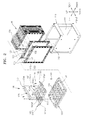
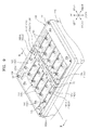
- FIG. 2 is an exploded perspective view schematically illustrating constituent elements of the battery pack of FIG. 1 , except for an insulation cover and a BMS.
- a battery pack may include a case 110, a plurality of battery units 120, an insulation plate 130, a plurality of bus bars 160, a printed circuit board (PCB) 170, an insulation cover 140, and a battery management system (BMS) 150.
- PCB printed circuit board
- BMS battery management system
- the case 110 may have a substantially hexahedral shape with an open upper surface for accommodating the battery units 120.
- the battery units 120 are accommodated in the case 110 to be parallel to one another.
- At least one lateral surface of the case 110 may be open to allow the battery units 120 to be exposed to external air.
- both of lateral surfaces of the case 110 may be open.
- the air introduced through a first opening 111 provided at one open lateral surface of the case 110 may be exhausted outside through a second opening 112 provided at the other open lateral surface by passing through the battery units 120 accommodated in the case 110.
- the case 110 may be formed of an insulation material.
- Each of the battery units 120 has a plate shape and includes a battery cell 123, first and second lead tabs 121 and 122 extending from one side of the battery cell 123, and a frame 125.
- the battery units 120 may be accommodated in the case 110 with first and second lead tabs 121 and 122 being exposed to the outside through the open upper surface of the case 110.
- the battery cell 123 may include, for example, a lithium-ion battery.
- the battery cell 123 may include an electrode assembly (not shown) in which a positive plate, a negative plate, and a plurality of separators interposed therebetween are stacked.
- an electrode assembly (not shown) in which a positive plate, a negative plate, and a plurality of separators interposed therebetween are stacked.
- a plurality of positive plates, negative plates, and separators may be stacked.
- the frame 125 may accommodate the battery cell 123.
- the frame 125 may be formed of an insulation material to secure insulation from the first and second lead tabs 121 and 122.
- the frame 125 may be formed of a polymer resin material such as polyphenylene sulphide (PPS).
- the first and second lead tabs 121 and 122 form interconnection with the outside of the battery cell 123 and may extend from one side of the battery cell 123 to guide current from the battery cell 123 to the outside.
- the first and second lead tabs 121 and 122 may extend toward one side, for example, an upper side, of the frame 125.
- the first and second lead tabs 121 and 122 may include a metal material exhibiting a superior conductivity, for example, aluminium (Al), copper (Cu), nickel (Ni), etc.
- the first and second lead tabs 121 and 122 may have the opposite polarities to each other.
- the first and second lead tabs 121 and 122 may serve as a positive tab and a negative tab, respectively.
- the first and second lead tabs 121 and 122 may be electrically connected to a positive plate (not shown) and a negative plate (not shown) of an electrode assembly (not shown), respectively.
- the first and second lead tabs 121 and 122 having the opposite polarities may be bent in the directions opposite to each other.
- the battery units 120 may be electrically connected using the first and second lead tabs 121 and 122.
- the first lead tab 121 may be bent forward with respect to the direction along which the battery units 120 are arranged, whereas the second lead tab 122 may be bent backward.
- the bending of the first and second lead tabs 121 and 122 may be performed after the provision of a first rib 131 of the insulation plate 130.
- the battery units 120 When the battery units 120 are arranged to form a battery module M, to allow the battery units 120 to be serially connected, suitable for high-voltage applications, the battery units 120 may be arranged with the first and second lead tabs 121 and 122 of one battery unit respectively facing the opposite tabs of a neighbouring battery unit. That is, the neighbouring battery units 120 are arranged so that the left and right sides of the first and second lead tabs 121 and 122 having the opposite polarities may be reversed between each battery unit. A pair of the battery units 120 neighbouring each other may form electrical connection by connecting the first and second lead tabs 121 and 122 of the different battery units 120 bent to face each other. For the electrical connection between the battery units 120, coupling holes 121h and 122h may be formed in the first and second lead tabs 121 and 122.
- the battery units 120 may be arranged in the battery module M such that they are connected in parallel, suitable for high-current applications. This is achieved by arranging the battery units such that first and second lead tabs 121 and 122 of one battery unit respectively face the same tabs of a neighbouring battery unit. That is, the neighbouring battery units 120 are arranged so that the left and right sides of the first and second lead tabs 121 and 122 having the opposite polarities have the same orientation.
- the first and second lead tabs 121 and 122 bent to face each other may be folded on each other on the first rib 131 of the insulation plate 130 and connected by a first bus bar 161 provided on the first and second lead tabs 121 and 122.
- the first bus bar 161 may include a coupling hole 161ah for mechanically coupling the first and second lead tabs 121 and 122 using a fourth fixing member 184.
- any one of the first and second lead tabs 121 and 122 of the battery units 120 located at the outermost position may not be folded on another lead tab.
- the first lead tab 121 of one of the battery units 120 that is located at the foremost position and the second lead tab 122 of one of the battery units 120 that is located at the rearmost position do not have lead tabs to face each other.
- bus bars 160 connected to the first lead tab 121 or the second lead tab 122 bent forward or backward may form a high current flow of a battery pack.
- a second bus bar 162 may be electrically connected to the first lead tab 121
- a third bus bar 163 may be electrically connected to the second lead tab 122.
- the second and third burs bars 162 and 163 may respectively include coupling holes 162ah and 163ah to be mechanically coupled to the first and second lead tabs 121 and 122 using the fourth fixing member 184.
- the bus bars 160 may include a metal material exhibiting superior conductivity, for example, aluminium (Al), copper (Cu), nickel (Ni), etc.
- the bus bars 160 may acquire cell balancing information of the battery units 120.
- the bus bars 160 may be electrically connected to the PCB 170 to acquire information about voltage of each of the battery units 120.
- the bus bars 160 may include coupling holes 161ch, 162ch, and 163ch to be mechanically coupled to the PCB 170 using a fifth fixing member 185.
- the insulation plate 130 may be arranged to cover the open upper portion of the case 110 and mechanically coupled to the case 110 using the first fixing member 181.
- the insulation plate 130 may support the first and second lead tabs 121 and 122 exposed to the upside of the case 110 and bent, and secure insulation between the bus bars 160.
- the insulation plate 130 may include the first rib 131 to stably support the first and second lead tabs 121 and 122 and the bus bars 160, and a second rib 132 to support some of the bus bars 160 and the PCB 170 for acquiring balancing of each battery cell 123.
- the first rib 131 may support the first and second lead tabs 121 and 122 bent forward or backward and the bus bars 160.
- the first rib 131 may form mechanical coupling with the fourth fixing member 184 that passes through the coupling holes 161ah, 162ah, and 163ah of the bus bars 160 and the coupling holes 121h and 122h of the first and second lead tabs 121 and 122.
- the second rib 132 may form mechanical coupling with the fifth fixing member 185 that passes through a coupling hole 170h of the PCB 170 and a coupling hole 160ch formed in the bus bars 160.
- the insulation plate 130 may include first and second terminal members 135 and 136.
- the first and second terminal members 135 and 136 may protrude in one direction to form interconnection with the outside of the battery pack.
- the second bus bar 162 connected to the first lead tab 121 located at the foremost position and the third bus bar 163 connected to the second lead tab 122 located at the rearmost position have the opposite polarities.
- the second bus bar 162 may be a positive pole of the battery module M
- the third bus bar 163 may be a negative pole of the battery module M.
- the second bus bar 162 is connected to the first terminal member 135 and the third bus bar 163 is connected to the second terminal member 136, thereby forming a high current flow of the battery pack.
- the PCB 170 is accommodated on the insulation plate 130 and electrically connected to each of the bus bars 160 so as to sense a voltage of each of the battery units120.
- the PCB 170 may sense a voltage of the battery cell 123 of each of the battery units 120 to monitor whether a voltage difference among the battery cells 123 within an allowable range.
- the voltage sensed by the PCB 170 may be transferred to the BMS 150 via a connector 175 formed on the PCB 170 and used for cell balancing.
- the BMS 150 may include a connector 155 that is connected to the connector 175 of the PCB 170 via a cable (not shown).
- the BMS 150 may compare the voltage of each battery cell 123 with a reference voltage and, when the voltage of each battery cell 123 is greater than the reference voltage, discharge is performed on the battery cell 123 having a voltage exceeding the reference voltage via a discharge path formed corresponding to each battery cell 123, thereby achieving cell balancing.
- the insulation cover 140 may be arranged to cover the insulation plate 130.
- the insulation cover 140 may be arranged in a state in which the first and second lead tabs 121 and 122 and the bus bars 160 are stably coupled via the insulation plate 130 and the PCB 170 is accommodated thereon.
- a second fixing member 182 may be bolt coupled to an upper portion of the insulation plate 130 by passing through a coupling hole 142 formed in the insulation cover 140.
- the insulation cover 140 may prevent short circuit by spatially separating the first and second terminal members 135 and 136 forming the high current flow.
- the insulation cover 140 may include recess portions 145 and 146 for accommodating the first and second lead tabs 121 and 122.
- the insulation cover 140 may prevent a short circuit by spatially separating the bus bars 160 supported on the insulation plate 130.
- a space for accommodating the BMS 150 is provided on an upper surface of the insulation cover 140.
- a third fixing member 183 may be coupled to a coupling hole 143 by passing through the BMS 150.
- a bolt may be used as the third fixing member 183.
- the BMS 150 includes the connector 155 capable of communicating with the PCB 170.
- An opening 141 may be provided in the insulation cover 140 so that the cable connecting the connector 175 of the PCB 170 and the connector 155 of the BMS 150 may pass through the opening 141.
- an outer cover may be further provided on the insulation cover 140 to protect the BMS 150.
- the insulation cover 140 as an inner cover may be coupled to the outer cover through a fixing member such as a bolt.
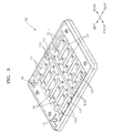
- FIG. 3 is a perspective view schematically illustrating the insulation plate 130.
- the insulation plate 130 may include a plurality of the first ribs 131 extending in a left and right direction and a plurality of the second ribs 132 extending in the forward and backward direction.
- the second ribs 132 may extend to across the centre of the insulation plate 130.
- the first ribs 131 that extend perpendicularly to the second ribs 132 may be arranged parallel to one another at both sides of the second ribs 132.
- an opening OP through which the first and second lead tabs 121 and 122 pass may be formed.
- the width of the opening OP may be equal to or larger than the width of the first and second lead tabs 121 and 122 so that the first and second lead tabs 121 and 122 may pass through the opening OP.
- the first ribs 131 support the first and second lead tabs 121 and 122.
- the first and second lead tabs 121 and 122 respectively provided at the neighbouring battery units 120 may be exposed to the outside by passing through the openings OP formed at both sides of one of the first ribs 131.
- the first and second lead tabs 121 and 122 passing through the openings OP may be bent in directions facing each other and supported by the first ribs 131.
- the first ribs 131 may simultaneously support the first and second lead tabs 121 and 122 or any one of the first and second lead tabs 121 and 122.
- first ribs 131 may support the bus bars 160 and have a plurality of coupling holes 131h for coupling to the fourth fixing member 184.
- the second rib 132 may extend along a lengthwise direction of the PCB 170 to accommodate the PCB 170.
- the fifth fixing member 185 may be coupled to the second rib 132 by passing through the PCB 170.
- a plurality of coupling holes 132h may be provided in the second rib 132.
- a spacer 137 to guide an accommodation position of the PCB 170 and prevent a movement of the PCB 170 may be provided at both ends of the second rib 132.
- first ribs 131 and the second rib 132 are formed to the same height, the present invention is not limited thereto.
- the second rib 132 may extend as high as the height of the upper surface of the spacer 137 to be higher than the first ribs 131.
- the first and second terminal members 135 and 136 may protrude upwardly to induce current from the battery pack to the outside.
- the first and second terminal members 135 and 136 may include a metal material exhibiting superior conductivity.
- the first and second terminal members 135 and 136 may include a material such as aluminium (Al), copper (Cu), nickel (Ni), etc.
- FIGS. 4A through 6B illustrate the bus bars 160 according to an embodiment of the present invention.
- FIG. 4A is a perspective view of the first bus bar 161.
- FIGS. 5A and 6A are perspective views of the second and third bus bars 162 and 163.
- FIGS. 4B , 5B, and 6B are cross-sectional views taken along lines IVb-IVb, Vb-Vb, and VIb-VIb of FIGS. 4A, 5A , and 6A , respectively.
- the first bus bar 161 may include a main body portion 161a, and a cell balancing portion 161c.
- the main body portion 161a may include an upper surface and side walls extending downwardly from both sides of the upper surface, to wrap the first and second lead tabs 121 and 122 bent on the first rib 131.
- the upper surface of the main body portion 161a may contact the bent first and second lead tabs 121 and 122 supported by the first rib 131, and the side walls provided at both sides of the main body portion 161a may respectively cover the first and second lead tabs 121 and 122. Only one side wall need be present however, which at least partially surrounds one side of the first rib 131.
- the first rib 131 comprises at least one side wall which is arranged to face a respective side wall of the first bus bar 161, as illustrated in FIG. 10 .
- the presence of the side walls of both the first rib 131 and the first bus bar 161 facilitates securing of the position of the first and second lead tabs 121 122 between the first rib 131 and the first bus bar 161.
- the main body portion 161a may be coupled to the first rib 131 with the bent first and second lead tabs 121 and 122 interposed therebetween. To this end, the main body portion 161a may include the coupling hole 161ah formed at a position corresponding to the coupling hole 131h that is formed in the first rib 131.
- the cell balancing portion 161c may protrude from one end of the main body portion 161a to transmit voltage information of the battery cell 123 included in each of the battery units 120 to the PCB 170. To this end, the cell balancing portion 161c may include the coupling hole 161ch for connection to the PCB 170.
- the second bus bar 162 may include a main body portion 162a, a cell balancing portion 162c, and a high current portion 162d.
- the main body portion 162a may include an upper surface and a side wall extending downwardly from one side of the upper surface to wrap the first lead tab 121 bent on the first rib 131.
- the upper surface of the main body portion 162a may contact the bent first lead tab 121 supported by the first rib 131, and the side wall may partially cover the first lead tab 121 that is not placed on the first rib 131.
- the main body portion 162a may be coupled to the first rib 131 with the bent first lead tab 121 interposed therebetween. To this end, the main body portion 162a may include the coupling hole 162ah formed at a position corresponding to the coupling hole 131h that is formed in the first rib 131.
- the cell balancing portion 162c may protrude from one end of the main body portion 162a to transmit voltage information of the battery cell 123 included in each of the battery units 120 to the PCB 170. To this end, the cell balancing portion 162c may include the coupling hole 162ch for connection to the PCB 170.
- the high current portion 162d may protrude from the other end of the main body portion 162a and include a through hole 162dh for coupling to the first terminal member 135. As the first terminal member 135 is inserted into the through hole 162dh, the high current portion 162d may be electrically connected to the first terminal member 135 in contact with the same.
- the third bus bar 163 may include a main body portion 163a, a cell balancing portion 163c, and a high current portion 163d.
- the main body portion 163a may include an upper surface and a side wall extending downwardly from one side of the upper surface to wrap the second lead tab 122 bent on the first rib 131.
- the upper surface of the main body portion 163a may contact the bent second lead tab 122 supported by the first rib 131, and the side wall may partially cover the second lead tab 122 that is not placed on the first rib 131.
- the main body portion 163a may be coupled to the first rib 131 with the bent second lead tab 122 interposed therebetween. To this end, the main body portion 163a may include the coupling hole 163ah formed at a position corresponding to the coupling hole 131h that is formed in the first rib 131.
- the cell balancing portion 163c may protrude from one end of the main body portion 163a to transmit voltage information of the battery cell 123 included in each of the battery units 120 to the PCB 170. To this end, the cell balancing portion 163c may include the coupling hole 163ch for connection to the PCB 170.
- the high current portion 163d may protrude from the other end of the main body portion 163a and include a through hole 163dh for coupling to the second terminal member 136. As the second terminal member 136 is inserted into the through hole 163dh, the high current portion 163d may be electrically connected to the second terminal member 136 in contact with the same.
- the present invention is not limited thereto.
- the cell balancing portions 161c, 162c, and 163c may be formed to be higher than the main body portions 161a, 162a, and 163a according to the height of the second rib 132.
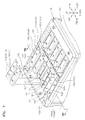
- FIG. 7 is a perspective view schematically illustrating the insulation plate 130 and the bus bars 160 arranged in an upper portion of the case 110 when the battery units 120 are accommodated in the case 110.
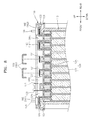
- FIG. 8 is a cross-sectional view taken along line VIII-VIII of FIG. 7 .
- FIG. 9 is a perspective view schematically illustrating a state in which the first and second lead tabs 121 and 122 and the bus bars 160 are coupled to each other on the insulation plate 130.
- FIG. 10 is a cross-sectional view taken along line X-X of FIG. 9 .
- the insulation plate 130 may be arranged on the case 110 such that the openings OP1 and OP2 can correspond to the first and second lead tabs 121 and 122 extending from the battery unit 120.
- the first and second lead tabs 121 and 122 extending from the neighbouring battery units 120 may be exposed to the outside by passing through the openings OP1 and OP2 provided at both sides of the first rib 131.
- the first and second lead tabs 121 and 122 exposed to the outside may be bent toward each other on the first rib 131.
- the bent first and second lead tabs 121 and 122 are folded over each other on the first rib 131, thereby serially connecting the neighbouring battery units 120.
- the hole 121h formed in the first lead tab 121 and the hole 122h formed in the second lead tab 122 may be aligned with the hole formed in the first rib 131.
- the first lead tab 121 extending through the opening OP1 provided at the foremost position is bent forward and accommodated on the first rib 131.
- the second lead tab 122 extending through an opening OP5 provided at the rearmost position is bent backward and accommodated on the first rib 131.
- the bus bars 160 may be accommodated on the first rib 131.
- the bus bars 160 may be arranged on the first lead tab 121 and/or the second lead tab 122 that are accommodated on the first rib 131.
- the cell balancing portion 160c of each of the bus bars 160 may be accommodated on the second rib 132.
- the hole 160ah formed in each of the bus bars 160 may be aligned with the holes 121h and 122h of the first and second lead tabs 121 and 122 and the hole of the first rib 131.
- the first bus bar 161 may be accommodated on the first and second lead tabs 121 and 122 folded over each other on the first rib 131
- the second bus bar 162 may be accommodated on the first lead tab 121 that is accommodated on the first rib 131
- the third bus bar 163 may be accommodated on the second lead tab 122 that is accommodated on the first rib 131.
- the high current portions 162d and 163d of second and third bus bars 162 and 163 may be coupled to the first and second terminal members 135 and 136, respectively.
- the first bus bar 161 may be fixed on the first rib 131 by the fourth fixing member 184.
- the fourth fixing member 184 may be coupled to the first rib 131 by passing through the hole 161ah formed in the first bus bar 161 and the holes 121h and 122h formed in the first and second lead tabs 121 and122.
- a bolt may be used as the fourth fixing member 184.
- the second bus bar 162 may be fixed on the first rib 131 using the fourth fixing member 184.
- the fourth fixing member 184 may be coupled to the first rib 131 by passing through the hole 162ah formed in the second bus bar 162 and the hole 121h formed in the first lead tab 121.
- the third bus bar 163 may be fixed on the first rib 131 using the fourth fixing member 184.
- the side walls of the bus bars 160 extend downwardly, i.e. toward the first lead tab 121 and/or the second lead tab 122, and cover the first lead tab 121 and/or the second lead tab 122, so that the bus bars 160 may protect the first and second lead tabs 121 and 122. since the first ribs 131 formed on the insulation plate 130 are separated from each other and the first and second lead tabs 121 and 122 and the bus bars 160 are coupled to the first ribs 131using the fourth fixing member 184, the connection there between may be stably maintained and short-circuits between the bus bars 160 and between the first and second lead tabs 121 and 122 may be prevented.69145
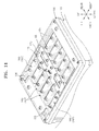
- FIG. 11 is a perspective view schematically illustrating a state in which the PCB 170 is accommodated on the bus bars 160.
- the PCB 170 is arranged to cover the cell balancing portion 160c of the bus bars 160 accommodated on the second rib 132.
- the cell balancing portion 160c may be electrically connected to a lower surface of the PCB 170 in contact with the same.
- the PCB 170 may be fixed on the insulation plate 130 using the fifth fixing member 185.
- the hole 160ch formed in the cell balancing portion 160c may be aligned with the hole 132h of the second rib 132.
- the fifth fixing member 185 may be coupled to the second rib 132 by passing through the PCB 170 and the cell balancing portion 160c.
- the voltage information of the battery cell 123 acquired through each cell balancing portion 160c is converged on the connector 175 via a wiring formed in the PCB 170 and is transferred to the BMS 150 via the cable connected to the connector 175, as described above.
Landscapes
- Chemical & Material Sciences (AREA)
- Chemical Kinetics & Catalysis (AREA)
- Electrochemistry (AREA)
- General Chemical & Material Sciences (AREA)
- Engineering & Computer Science (AREA)
- Manufacturing & Machinery (AREA)
- Microelectronics & Electronic Packaging (AREA)
- Connection Of Batteries Or Terminals (AREA)
- Battery Mounting, Suspending (AREA)
Description
- The present invention relates to a battery pack.
- Secondary batteries refer to batteries capable of being charged or discharged unlike primary batteries that are not chargeable, and the secondary battery has been widely used not only for compact electronic devices such as mobile phones, personal digital assistants (PDAs), notebook computers, etc. but also for energy storage systems. During assembly or carrying of a secondary battery, a conductor may contact a terminal so that a positive electrode and a negative electrode are short-circuited, which may cause heating or firing of the secondary battery.
- United States Patent Application No.
US 2008/124617 discloses an example of a battery pack in which terminal tabs from each cell of a plurality of cells extend through holes in a bus bar, and tabs extending through a pair of holes are folded one over the other. - International Patent Application No.
WO 2010/071464 discloses another example of clamping together poles of neighbouring battery cells, between a support and a cover. - According to an aspect of the present invention, there is provided a battery pack comprising a plurality of battery units arranged within a case, each battery unit including first and second electrode tabs, and an insulation plate mounted to the case, the insulation plate having a plurality of first ribs, and a plurality of first bus bars, each first bus bar arranged to cover a respective first rib of the insulation plate, wherein each first bus bar connects a first electrode tab of a first battery unit and a second electrode tab of a second battery unit, the first and second electrode tabs disposed on the first rib which is covered by the first bus bar.
- In this manner, connection of the battery units is made possible in a manner in which short circuiting between electrode tabs can be prevented by the separation of the ribs, and the covering of the bus bars.
- The battery pack may further comprise a terminal member, and a second bus bar arranged to connect the terminal member to a first electrode tab of one of the plurality of battery units.
- The battery pack further comprises second ribs arranged perpendicular to the first ribs, wherein each of the first and second bus bars (161, 162) is fixed to a second rib.
- The first ribs may be divided into two groups, and the second ribs may be arranged between the two groups of first ribs.
- Each first bus bar has a main body portion arranged to cover the first rib, and a cell-balancing portion arranged to cover a portion of the second rib. The battery pack may comprise a printed circuit board coupled to the cell-balancing portion of the first bus bar, the printed circuit board arranged to provide battery unit voltage information to a battery management system.
- The main body portion of each first bus bar may comprise at least one side wall arranged to at least partially surround at least one side of a respective first rib.
The first rib may comprise at least one side wall arranged to face the side wall of the first bus bar.
The second bus bar may comprise a main body portion covering a first rib, a current-balancing portion covering a portion of the second rib, and a high-current portion to which the terminal member is connected. - The battery pack may comprise a further terminal member, the terminal members separated by an insulation cover covering the insulation plate.
The insulation cover may be arranged to spatially separate the first bus bars . - The first electrode tab of the first battery unit and the second electrode tab of the second battery unit protrude through openings in the insulation plate either side of the first rib on which they are to be disposed, the first and second electrode tabs folded towards each other such that they are supported by the first rib.
- Each first bus bar is attached to the first electrode tab of a first battery unit, the second electrode tab of a second battery unit, and the rib, using a fixing member.
The first electrode tab of the first battery unit has a different polarity from the second electrode tab of the second battery unit, such that the battery units are serially connected by a first bus bar. - The first electrode tab of the first battery unit has the same polarity as the second electrode tab of the second battery unit, such that the battery units are connected in parallel by a first bus bar.
- Embodiments of the present invention will now be described by way of example only, with reference to the accompany drawings, in which:
-
FIG. 1 is a perspective view schematically illustrating a battery pack according to an embodiment of the present invention; -
FIG. 2 is an exploded perspective view schematically illustrating constituent elements of the battery pack ofFIG. 1 , except for an insulation cover and a BMS; -
FIG. 3 is a perspective view schematically illustrating an insulation plate; -
FIG. 4A is a perspective view of a first bus bar; -
FIG. 4B is a cross-sectional view taken along line IVb-IVb ofFIG. 4A ; -
FIG. 5A is a perspective view of a second bus bar; -
FIG. 5B is a cross-sectional view taken along line Vb-Vb ofFIG. 5A ; -
FIG. 6A is a perspective view of a third bus bar; -
FIG. 6B is a cross-sectional view taken along line VIb-VIb ofFIG. 6A ; -
FIG. 7 is a perspective view schematically illustrating an insulation plate and a bus bar arranged in an upper portion of a case when battery units are accommodated in the case; -
FIG. 8 is a cross-sectional view taken along line VIII-VIII ofFIG. 7 ; -
FIG. 9 is a perspective view schematically illustrating a state in which first and second lead tabs and a bus bar are coupled to each other on an insulation plate; -
FIG. 10 is a cross-sectional view taken along line X-X ofFIG. 9 ; and -
FIG. 11 is a perspective view schematically illustrating a state in which a PCB is accommodated on a bus bar. - The present invention will now be described more fully with reference to the accompanying drawings, in which exemplary embodiments of the invention are shown. The invention may, however, be embodied in many different forms and should not be construed as being limited to the embodiments set forth herein; rather, these embodiments are provided so that this disclosure will be thorough and complete, and will fully convey the concept of the invention to those skilled in the art. The scope of the present invention is defined by the following claims. In the meantime, the terms used in the present specification are used for explaining a specific exemplary embodiment, not limiting the present inventive concept. Thus, the expression of singularity in the present specification includes the expression of plurality unless clearly specified otherwise in context. Also, the terms such as "comprise" and/or "comprising" may be construed to denote a certain characteristic, number, step, operation, constituent element, or a combination thereof, but may not be construed to exclude the existence of or a possibility of addition of one or more other characteristics, numbers, steps, operations, constituent elements, or combinations thereof. In the present specification, the terms such as "first" and "second" are used herein merely to describe a variety of members, parts, areas, layers, and/or portions, but the constituent elements are not limited by the terms. The terms are used only for the purpose of distinguishing one constituent element from another constituent element. To help understanding of the invention, like reference numerals refer to like elements throughout.
-
FIG. 1 is a perspective view schematically illustrating a battery pack according to an embodiment of the present invention.FIG. 2 is an exploded perspective view schematically illustrating constituent elements of the battery pack ofFIG. 1 , except for an insulation cover and a BMS. - Referring to
FIGS. 1 and2 , a battery pack according to the present embodiment may include acase 110, a plurality ofbattery units 120, aninsulation plate 130, a plurality ofbus bars 160, a printed circuit board (PCB) 170, aninsulation cover 140, and a battery management system (BMS) 150. - The
case 110 may have a substantially hexahedral shape with an open upper surface for accommodating thebattery units 120. Thebattery units 120 are accommodated in thecase 110 to be parallel to one another. At least one lateral surface of thecase 110 may be open to allow thebattery units 120 to be exposed to external air. For example, both of lateral surfaces of thecase 110 may be open. The air introduced through afirst opening 111 provided at one open lateral surface of thecase 110 may be exhausted outside through asecond opening 112 provided at the other open lateral surface by passing through thebattery units 120 accommodated in thecase 110. Thecase 110 may be formed of an insulation material. - Each of the
battery units 120 has a plate shape and includes abattery cell 123, first and secondlead tabs battery cell 123, and aframe 125. Thebattery units 120 may be accommodated in thecase 110 with first and secondlead tabs case 110. - The
battery cell 123 may include, for example, a lithium-ion battery. Thebattery cell 123 may include an electrode assembly (not shown) in which a positive plate, a negative plate, and a plurality of separators interposed therebetween are stacked. To provide thebattery units 120 of high output and high capacity, a plurality of positive plates, negative plates, and separators may be stacked. - The
frame 125 may accommodate thebattery cell 123. Theframe 125 may be formed of an insulation material to secure insulation from the first and secondlead tabs frame 125 may be formed of a polymer resin material such as polyphenylene sulphide (PPS). - The first and second
lead tabs battery cell 123 and may extend from one side of thebattery cell 123 to guide current from thebattery cell 123 to the outside. The first and secondlead tabs frame 125. The first and secondlead tabs - The first and second
lead tabs lead tabs lead tabs - The first and second
lead tabs battery units 120 may be electrically connected using the first and secondlead tabs first lead tab 121 may be bent forward with respect to the direction along which thebattery units 120 are arranged, whereas thesecond lead tab 122 may be bent backward. The bending of the first and secondlead tabs first rib 131 of theinsulation plate 130. - When the
battery units 120 are arranged to form a battery module M, to allow thebattery units 120 to be serially connected, suitable for high-voltage applications, thebattery units 120 may be arranged with the first and secondlead tabs battery units 120 are arranged so that the left and right sides of the first and secondlead tabs battery units 120 neighbouring each other may form electrical connection by connecting the first and secondlead tabs different battery units 120 bent to face each other. For the electrical connection between thebattery units 120, coupling holes 121h and 122h may be formed in the first and secondlead tabs - Alternatively, the
battery units 120 may be arranged in the battery module M such that they are connected in parallel, suitable for high-current applications. This is achieved by arranging the battery units such that first and secondlead tabs battery units 120 are arranged so that the left and right sides of the first and secondlead tabs - The first and second
lead tabs first rib 131 of theinsulation plate 130 and connected by afirst bus bar 161 provided on the first and secondlead tabs first bus bar 161 may include a coupling hole 161ah for mechanically coupling the first and secondlead tabs member 184. - When the neighbouring
battery units 120 are arranged so that the left and right sides of the first and secondlead tabs battery units 120, any one of the first and secondlead tabs battery units 120 located at the outermost position may not be folded on another lead tab. For example, thefirst lead tab 121 of one of thebattery units 120 that is located at the foremost position and thesecond lead tab 122 of one of thebattery units 120 that is located at the rearmost position do not have lead tabs to face each other. - Some of the bus bars 160 connected to the
first lead tab 121 or thesecond lead tab 122 bent forward or backward may form a high current flow of a battery pack. For example, asecond bus bar 162 may be electrically connected to thefirst lead tab 121, whereas athird bus bar 163 may be electrically connected to thesecond lead tab 122. To this end, the second and third burs bars 162 and 163 may respectively include coupling holes 162ah and 163ah to be mechanically coupled to the first and secondlead tabs member 184. The bus bars 160 may include a metal material exhibiting superior conductivity, for example, aluminium (Al), copper (Cu), nickel (Ni), etc. - The bus bars 160 may acquire cell balancing information of the
battery units 120. The bus bars 160 may be electrically connected to thePCB 170 to acquire information about voltage of each of thebattery units 120. To this end, the bus bars 160 may include coupling holes 161ch, 162ch, and 163ch to be mechanically coupled to thePCB 170 using a fifth fixingmember 185. - The
insulation plate 130 may be arranged to cover the open upper portion of thecase 110 and mechanically coupled to thecase 110 using the first fixingmember 181. Theinsulation plate 130 may support the first and secondlead tabs case 110 and bent, and secure insulation between the bus bars 160. - To this end, the
insulation plate 130 may include thefirst rib 131 to stably support the first and secondlead tabs second rib 132 to support some of the bus bars 160 and thePCB 170 for acquiring balancing of eachbattery cell 123. - The
first rib 131 may support the first and secondlead tabs first rib 131 may form mechanical coupling with the fourth fixingmember 184 that passes through the coupling holes 161ah, 162ah, and 163ah of the bus bars 160 and the coupling holes 121h and 122h of the first and secondlead tabs - The
second rib 132 may form mechanical coupling with the fifth fixingmember 185 that passes through acoupling hole 170h of thePCB 170 and a coupling hole 160ch formed in the bus bars 160. - The
insulation plate 130 may include first and secondterminal members terminal members battery units 120 are electrically connected to one another, thesecond bus bar 162 connected to thefirst lead tab 121 located at the foremost position and thethird bus bar 163 connected to thesecond lead tab 122 located at the rearmost position have the opposite polarities. For example, thesecond bus bar 162 may be a positive pole of the battery module M, whereas thethird bus bar 163 may be a negative pole of the battery module M. Thesecond bus bar 162 is connected to thefirst terminal member 135 and thethird bus bar 163 is connected to thesecond terminal member 136, thereby forming a high current flow of the battery pack. - The
PCB 170 is accommodated on theinsulation plate 130 and electrically connected to each of the bus bars 160 so as to sense a voltage of each of the battery units120. ThePCB 170 may sense a voltage of thebattery cell 123 of each of thebattery units 120 to monitor whether a voltage difference among thebattery cells 123 within an allowable range. - The voltage sensed by the
PCB 170 may be transferred to the BMS 150 via aconnector 175 formed on thePCB 170 and used for cell balancing. To this end, the BMS 150 may include aconnector 155 that is connected to theconnector 175 of thePCB 170 via a cable (not shown). The BMS 150 may compare the voltage of eachbattery cell 123 with a reference voltage and, when the voltage of eachbattery cell 123 is greater than the reference voltage, discharge is performed on thebattery cell 123 having a voltage exceeding the reference voltage via a discharge path formed corresponding to eachbattery cell 123, thereby achieving cell balancing. - The
insulation cover 140 may be arranged to cover theinsulation plate 130. Theinsulation cover 140 may be arranged in a state in which the first and secondlead tabs insulation plate 130 and thePCB 170 is accommodated thereon. Asecond fixing member 182 may be bolt coupled to an upper portion of theinsulation plate 130 by passing through acoupling hole 142 formed in theinsulation cover 140. - The
insulation cover 140 may prevent short circuit by spatially separating the first and secondterminal members insulation cover 140 may includerecess portions lead tabs insulation cover 140 may prevent a short circuit by spatially separating the bus bars 160 supported on theinsulation plate 130. - A space for accommodating the BMS 150 is provided on an upper surface of the
insulation cover 140. Athird fixing member 183 may be coupled to acoupling hole 143 by passing through the BMS 150. For example, a bolt may be used as the third fixingmember 183. The BMS 150 includes theconnector 155 capable of communicating with thePCB 170. Anopening 141 may be provided in theinsulation cover 140 so that the cable connecting theconnector 175 of thePCB 170 and theconnector 155 of the BMS 150 may pass through theopening 141. - Although it is not illustrated in the drawing, an outer cover may be further provided on the
insulation cover 140 to protect the BMS 150. Theinsulation cover 140 as an inner cover may be coupled to the outer cover through a fixing member such as a bolt. -
FIG. 3 is a perspective view schematically illustrating theinsulation plate 130. - Referring to
FIG. 3 , theinsulation plate 130 may include a plurality of thefirst ribs 131 extending in a left and right direction and a plurality of thesecond ribs 132 extending in the forward and backward direction. Thesecond ribs 132 may extend to across the centre of theinsulation plate 130. Thefirst ribs 131 that extend perpendicularly to thesecond ribs 132 may be arranged parallel to one another at both sides of thesecond ribs 132. - As the
first ribs 131 are separated from one another in the forward and backward direction, an opening OP through which the first and secondlead tabs lead tabs lead tabs - The
first ribs 131 support the first and secondlead tabs lead tabs battery units 120 may be exposed to the outside by passing through the openings OP formed at both sides of one of thefirst ribs 131. The first and secondlead tabs first ribs 131. Thefirst ribs 131 may simultaneously support the first and secondlead tabs lead tabs - Also, the
first ribs 131 may support the bus bars 160 and have a plurality ofcoupling holes 131h for coupling to the fourth fixingmember 184. - The
second rib 132 may extend along a lengthwise direction of thePCB 170 to accommodate thePCB 170. For example, the fifth fixingmember 185 may be coupled to thesecond rib 132 by passing through thePCB 170. To this end, a plurality ofcoupling holes 132h may be provided in thesecond rib 132. Aspacer 137 to guide an accommodation position of thePCB 170 and prevent a movement of thePCB 170 may be provided at both ends of thesecond rib 132. - Although in the present embodiment the
first ribs 131 and thesecond rib 132 are formed to the same height, the present invention is not limited thereto. For example, thesecond rib 132 may extend as high as the height of the upper surface of thespacer 137 to be higher than thefirst ribs 131. - The first and second
terminal members terminal members terminal members FIGS. 4A through 6B illustrate the bus bars 160 according to an embodiment of the present invention.FIG. 4A is a perspective view of thefirst bus bar 161.FIGS. 5A and6A are perspective views of the second and third bus bars 162 and 163.FIGS. 4B ,5B, and 6B are cross-sectional views taken along lines IVb-IVb, Vb-Vb, and VIb-VIb ofFIGS. 4A, 5A , and6A , respectively. - Referring to
FIGS. 4A and 4B , thefirst bus bar 161 may include amain body portion 161a, and acell balancing portion 161c. Themain body portion 161a may include an upper surface and side walls extending downwardly from both sides of the upper surface, to wrap the first and secondlead tabs first rib 131. The upper surface of themain body portion 161a may contact the bent first and secondlead tabs first rib 131, and the side walls provided at both sides of themain body portion 161a may respectively cover the first and secondlead tabs first rib 131. Correspondingly, thefirst rib 131 comprises at least one side wall which is arranged to face a respective side wall of thefirst bus bar 161, as illustrated inFIG. 10 . The presence of the side walls of both thefirst rib 131 and thefirst bus bar 161 facilitates securing of the position of the first and secondlead tabs 121 122 between thefirst rib 131 and thefirst bus bar 161. - The
main body portion 161a may be coupled to thefirst rib 131 with the bent first and secondlead tabs main body portion 161a may include the coupling hole 161ah formed at a position corresponding to thecoupling hole 131h that is formed in thefirst rib 131. - The
cell balancing portion 161c may protrude from one end of themain body portion 161a to transmit voltage information of thebattery cell 123 included in each of thebattery units 120 to thePCB 170. To this end, thecell balancing portion 161c may include the coupling hole 161ch for connection to thePCB 170. - Referring to
FIGS. 5A and5B , thesecond bus bar 162 may include amain body portion 162a, acell balancing portion 162c, and a highcurrent portion 162d. Themain body portion 162a may include an upper surface and a side wall extending downwardly from one side of the upper surface to wrap thefirst lead tab 121 bent on thefirst rib 131. The upper surface of themain body portion 162a may contact the bentfirst lead tab 121 supported by thefirst rib 131, and the side wall may partially cover thefirst lead tab 121 that is not placed on thefirst rib 131. - The
main body portion 162a may be coupled to thefirst rib 131 with the bentfirst lead tab 121 interposed therebetween. To this end, themain body portion 162a may include the coupling hole 162ah formed at a position corresponding to thecoupling hole 131h that is formed in thefirst rib 131. - The
cell balancing portion 162c may protrude from one end of themain body portion 162a to transmit voltage information of thebattery cell 123 included in each of thebattery units 120 to thePCB 170. To this end, thecell balancing portion 162c may include the coupling hole 162ch for connection to thePCB 170. - The high
current portion 162d may protrude from the other end of themain body portion 162a and include a through hole 162dh for coupling to thefirst terminal member 135. As thefirst terminal member 135 is inserted into the through hole 162dh, the highcurrent portion 162d may be electrically connected to thefirst terminal member 135 in contact with the same. - Referring to
FIGS. 6A and 6B , thethird bus bar 163 may include amain body portion 163a, acell balancing portion 163c, and a highcurrent portion 163d. Themain body portion 163a may include an upper surface and a side wall extending downwardly from one side of the upper surface to wrap thesecond lead tab 122 bent on thefirst rib 131. The upper surface of themain body portion 163a may contact the bentsecond lead tab 122 supported by thefirst rib 131, and the side wall may partially cover thesecond lead tab 122 that is not placed on thefirst rib 131. - The
main body portion 163a may be coupled to thefirst rib 131 with the bentsecond lead tab 122 interposed therebetween. To this end, themain body portion 163a may include the coupling hole 163ah formed at a position corresponding to thecoupling hole 131h that is formed in thefirst rib 131. - The
cell balancing portion 163c may protrude from one end of themain body portion 163a to transmit voltage information of thebattery cell 123 included in each of thebattery units 120 to thePCB 170. To this end, thecell balancing portion 163c may include the coupling hole 163ch for connection to thePCB 170. - The high
current portion 163d may protrude from the other end of themain body portion 163a and include a through hole 163dh for coupling to thesecond terminal member 136. As thesecond terminal member 136 is inserted into the through hole 163dh, the highcurrent portion 163d may be electrically connected to thesecond terminal member 136 in contact with the same. - Although in
FIGS. 4A through 6B themain body portions cell balancing portions second rib 132 is formed to be higher than thefirst rib 131 in theinsulation plate 130 described with reference toFIG. 3 , thecell balancing portions main body portions second rib 132. - The connections between the first and second
lead tabs PCB 170 using theinsulation plate 130 are described below with reference toFIGS. 7 through 11 . -
FIG. 7 is a perspective view schematically illustrating theinsulation plate 130 and the bus bars 160 arranged in an upper portion of thecase 110 when thebattery units 120 are accommodated in thecase 110.FIG. 8 is a cross-sectional view taken along line VIII-VIII ofFIG. 7 .FIG. 9 is a perspective view schematically illustrating a state in which the first and secondlead tabs insulation plate 130.FIG. 10 is a cross-sectional view taken along line X-X ofFIG. 9 . - Referring to
FIGS. 7 and8 , theinsulation plate 130 may be arranged on thecase 110 such that the openings OP1 and OP2 can correspond to the first and secondlead tabs battery unit 120. The first and secondlead tabs battery units 120 may be exposed to the outside by passing through the openings OP1 and OP2 provided at both sides of thefirst rib 131. The first and secondlead tabs first rib 131. - The bent first and second
lead tabs first rib 131, thereby serially connecting the neighbouringbattery units 120. Thehole 121h formed in thefirst lead tab 121 and thehole 122h formed in thesecond lead tab 122 may be aligned with the hole formed in thefirst rib 131. - The
first lead tab 121 extending through the opening OP1 provided at the foremost position is bent forward and accommodated on thefirst rib 131. Thesecond lead tab 122 extending through an opening OP5 provided at the rearmost position is bent backward and accommodated on thefirst rib 131. - Then, the bus bars 160 may be accommodated on the
first rib 131. For example, the bus bars 160 may be arranged on thefirst lead tab 121 and/or thesecond lead tab 122 that are accommodated on thefirst rib 131. Thecell balancing portion 160c of each of the bus bars 160 may be accommodated on thesecond rib 132. The hole 160ah formed in each of the bus bars 160 may be aligned with theholes lead tabs first rib 131. - Referring to
FIGS. 9 and10 , thefirst bus bar 161 may be accommodated on the first and secondlead tabs first rib 131, thesecond bus bar 162 may be accommodated on thefirst lead tab 121 that is accommodated on thefirst rib 131, and thethird bus bar 163 may be accommodated on thesecond lead tab 122 that is accommodated on thefirst rib 131. The highcurrent portions terminal members - Referring to
FIGS. 7 through 10 , thefirst bus bar 161 may be fixed on thefirst rib 131 by the fourth fixingmember 184. Thefourth fixing member 184 may be coupled to thefirst rib 131 by passing through the hole 161ah formed in thefirst bus bar 161 and theholes lead tabs 121 and122. A bolt may be used as the fourth fixingmember 184. - The
second bus bar 162 may be fixed on thefirst rib 131 using the fourth fixingmember 184. Thefourth fixing member 184 may be coupled to thefirst rib 131 by passing through the hole 162ah formed in thesecond bus bar 162 and thehole 121h formed in thefirst lead tab 121. Thethird bus bar 163 may be fixed on thefirst rib 131 using the fourth fixingmember 184. - The side walls of the bus bars 160 extend downwardly, i.e. toward the
first lead tab 121 and/or thesecond lead tab 122, and cover thefirst lead tab 121 and/or thesecond lead tab 122, so that the bus bars 160 may protect the first and secondlead tabs first ribs 131 formed on theinsulation plate 130 are separated from each other and the first and secondlead tabs member 184, the connection there between may be stably maintained and short-circuits between the bus bars 160 and between the first and secondlead tabs -
FIG. 11 is a perspective view schematically illustrating a state in which thePCB 170 is accommodated on the bus bars 160. - Referring to
FIGS. 9 through 11 , thePCB 170 is arranged to cover thecell balancing portion 160c of the bus bars 160 accommodated on thesecond rib 132. Thecell balancing portion 160c may be electrically connected to a lower surface of thePCB 170 in contact with the same. To this end, thePCB 170 may be fixed on theinsulation plate 130 using the fifth fixingmember 185. The hole 160ch formed in thecell balancing portion 160c may be aligned with thehole 132h of thesecond rib 132. Thefifth fixing member 185 may be coupled to thesecond rib 132 by passing through thePCB 170 and thecell balancing portion 160c. - The voltage information of the
battery cell 123 acquired through eachcell balancing portion 160c is converged on theconnector 175 via a wiring formed in thePCB 170 and is transferred to the BMS 150 via the cable connected to theconnector 175, as described above.
Claims (14)
- A battery pack comprising:a plurality of battery units (120) arranged within a case (110), each battery unit including first (121) and second (122) electrode tabs; andan insulation plate (130) mounted to the case, the insulation plate having a plurality of first ribs (131), anda plurality of first bus bars (161), each first bus bar arranged to cover a respective first rib of the insulation plate;wherein each first bus bar connects a first electrode tab of a first battery unit and a second electrode tab of a second battery unit, the first and second electrode tabs disposed on the first rib which is covered by the first bus bar,the battery pack characterized in that the insulation plate (130) further comprises second ribs (132) arranged perpendicular to the first ribs (131), wherein each of the first bus bars (161) is fixed to a second rib,wherein each first bus bar has a main body portion (161a) arranged to cover the first rib (131) and a cell-balancing portion (161c) arranged to cover a portion of the second rib.
- A battery pack according to claim 1, comprising:a terminal member (135); anda second bus bar (162) arranged to connect the terminal member (135) to a first electrode tab (121) of one of the plurality of battery units.
- A battery pack according to claim 2, wherein the second bus bar (162) is fixed to a second rib.
- A battery pack according to claim 3 wherein the first ribs (131) are divided into two groups, and the second ribs (132) are arranged between the two groups of first ribs.
- A battery pack according to any one of claims 2 to 4, comprising a printed circuit board (170) coupled to the cell-balancing portion of the first bus bar, the printed circuit board arranged to provide battery unit voltage information to a battery management system (150).
- A battery pack according to claim 4 or claim 5, wherein the main body portion (161a) of each first bus bar (161) comprises at least one side wall arranged to at least partially surround at least one side of a respective first rib (131).
- A battery pack according to claim 6, the first rib (131) comprising at least one side wall arranged to face the side wall of the first bus bar (161).
- A battery pack according to any one of claims 2 to 7, wherein the second bus bar (162) comprises a main body portion (162a) covering a first rib (131), a current-balancing portion (162c) covering a portion of the second rib (132), and a high-current portion (162d) to which the terminal member is connected.
- A battery pack according to any one of claims 2 to 8 comprising a further terminal member (136), the terminal members (135, 136) separated by an insulation cover (140) covering the insulation plate (130).
- A battery pack according to claim 9, wherein the insulation cover (140) is arranged to spatially separate the first bus bars (160).
- A battery pack according to any one of the preceding claims, wherein the first electrode tab (121) of the first battery unit and the second electrode tab (122) of the second battery unit protrude through openings (OP1, OP2) in the insulation plate (130) either side of the first rib (131) on which they are to be disposed, the first and second electrode tabs folded towards each other such that they are supported by the first rib.
- A battery pack according to any one of the preceding claims, wherein each first bus bar (161) is attached to the first electrode tab (121) of a first battery unit, the second electrode tab (122) of a second battery unit, and the rib (130), using a fixing member (184).
- A battery pack according to any one of the preceding claims, wherein the first electrode tab (121) of the first battery unit has a different polarity from the second electrode tab (122) of the second battery unit, such that the battery units are serially connected by a first bus bar (161).
- A battery pack according to any one of claims 1 to 13, wherein the first electrode tab (121) of the first battery unit has the same polarity as the second electrode tab (122) of the second battery unit, such that the battery units are connected in parallel by a first bus bar (161).
Applications Claiming Priority (2)
| Application Number | Priority Date | Filing Date | Title |
|---|---|---|---|
| US201161500341P | 2011-06-23 | 2011-06-23 | |
| US13/243,457 US8609276B2 (en) | 2011-06-23 | 2011-09-23 | Battery pack |
Publications (3)
| Publication Number | Publication Date |
|---|---|
| EP2538469A2 EP2538469A2 (en) | 2012-12-26 |
| EP2538469A3 EP2538469A3 (en) | 2013-12-18 |
| EP2538469B1 true EP2538469B1 (en) | 2016-09-14 |
Family
ID=45887932
Family Applications (1)
| Application Number | Title | Priority Date | Filing Date |
|---|---|---|---|
| EP12159294.3A Active EP2538469B1 (en) | 2011-06-23 | 2012-03-13 | Battery pack |
Country Status (4)
| Country | Link |
|---|---|
| US (1) | US8609276B2 (en) |
| EP (1) | EP2538469B1 (en) |
| KR (2) | KR20130023059A (en) |
| CN (1) | CN102842695B (en) |
Cited By (2)
| Publication number | Priority date | Publication date | Assignee | Title |
|---|---|---|---|---|
| TWI642245B (en) * | 2017-07-24 | 2018-11-21 | 莫仕有限公司 | Battery connection module |
| KR101937942B1 (en) | 2015-07-13 | 2019-01-11 | 주식회사 엘지화학 | Bus-bar Structure |
Families Citing this family (66)
| Publication number | Priority date | Publication date | Assignee | Title |
|---|---|---|---|---|
| JP5714716B2 (en) * | 2011-10-13 | 2015-05-07 | 株式会社ケーヒン | Power control device |
| TWI441578B (en) * | 2012-01-11 | 2014-06-11 | Delta Electronics Inc | Circuit board assembly |
| GB2500604A (en) * | 2012-03-26 | 2013-10-02 | Leclanche Sa | Battery Cell electrical connections |
| US9799872B2 (en) * | 2013-01-18 | 2017-10-24 | Samsung Sdi Co., Ltd. | Battery module |
| WO2015103548A1 (en) | 2014-01-03 | 2015-07-09 | Quantumscape Corporation | Thermal management system for vehicles with an electric powertrain |
| CN104904033B (en) * | 2013-04-15 | 2018-03-09 | 株式会社Lg 化学 | Battery module with novel structure and the battery pack including the battery module |
| KR101636444B1 (en) * | 2013-06-20 | 2016-07-05 | 주식회사 엘지화학 | Battery Module and Battery Pack Comprising the Same |
| WO2015021435A2 (en) * | 2013-08-09 | 2015-02-12 | Apple Inc. | Battery core hermetic casing |
| US9660244B2 (en) | 2013-09-06 | 2017-05-23 | Johnson Controls Technology Company | System and method for establishing connections of a battery module |
| KR101636380B1 (en) * | 2013-09-26 | 2016-07-05 | 주식회사 엘지화학 | Voltage Sensing Assembly and Battery Module Including the Same |
| US11011783B2 (en) * | 2013-10-25 | 2021-05-18 | Quantumscape Battery, Inc. | Thermal and electrical management of battery packs |
| US9397328B2 (en) * | 2014-01-22 | 2016-07-19 | Ford Global Technologies, Llc | Flexible busbar holder for welded cells |
| KR101523588B1 (en) * | 2014-05-08 | 2015-05-28 | 안동대학교 산학협력단 | Secondary battery assembly |
| CN106575724B (en) * | 2014-05-29 | 2019-05-07 | 株式会社Lg 化学 | Battery module with insulation moulding part |
| KR101737489B1 (en) | 2014-06-05 | 2017-05-18 | 주식회사 엘지화학 | Battery pack having improved structure for supporting torque of terminal bolt |
| JP2015230892A (en) * | 2014-06-09 | 2015-12-21 | ソニー株式会社 | Battery module, power storage device, power storage system, electronic apparatus, electric vehicle and power system |
| CN104659320B (en) * | 2014-06-25 | 2017-09-15 | 湖北骆驼蓄电池研究院有限公司 | Cell polar ear attachment means and method |
| US9705121B2 (en) * | 2014-08-18 | 2017-07-11 | Johnson Controls Technology Company | Lead frame for a battery module |
| US9834114B2 (en) | 2014-08-27 | 2017-12-05 | Quantumscape Corporation | Battery thermal management system and methods of use |
| US9520587B2 (en) | 2014-09-30 | 2016-12-13 | Johnson Controls Technology Company | Bus bar assembly carrier |
| CN104377325B (en) * | 2014-11-04 | 2017-07-14 | 惠州市德赛电池有限公司 | A kind of vehicle-mounted startup power supply |
| KR101640100B1 (en) * | 2014-11-10 | 2016-07-18 | 한국단자공업 주식회사 | Series connection apparatus of battery module |
| KR102379560B1 (en) * | 2015-02-25 | 2022-03-28 | 삼성에스디아이 주식회사 | Battery pack |
| KR102384022B1 (en) * | 2015-02-25 | 2022-04-07 | 삼성에스디아이 주식회사 | Battery pack |
| KR102379562B1 (en) * | 2015-02-25 | 2022-03-28 | 삼성에스디아이 주식회사 | Battery pack |
| KR102381777B1 (en) * | 2015-02-25 | 2022-04-01 | 삼성에스디아이 주식회사 | Battery pack |
| USD763193S1 (en) | 2015-06-02 | 2016-08-09 | Johnson Controls Technology Controls | Bus bar carrier for lithium ion battery module |
| KR102397218B1 (en) * | 2015-08-27 | 2022-05-12 | 삼성에스디아이 주식회사 | Battery pack |
| CN105244467B (en) * | 2015-09-16 | 2017-09-29 | 浙江超威创元实业有限公司 | A kind of compression joint type power battery pack assembling structure, assemble method and electric car |
| WO2017117720A1 (en) * | 2016-01-05 | 2017-07-13 | 宁德时代新能源科技股份有限公司 | Battery module and battery pack |
| KR102012403B1 (en) * | 2016-09-13 | 2019-08-20 | 주식회사 엘지화학 | Intergrated Cartridge for battery cell and Battery Pack having the same |
| EP3416209B1 (en) * | 2016-02-12 | 2022-06-29 | LG Energy Solution, Ltd. | Integrated cartridge and battery pack comprising same |
| KR102082903B1 (en) | 2016-02-22 | 2020-02-28 | 주식회사 엘지화학 | Battery module, battery pack comprising the battery module and vehicle comprising the battery pack |
| KR102119183B1 (en) * | 2016-08-18 | 2020-06-04 | 주식회사 엘지화학 | Battery module |
| KR102210886B1 (en) | 2016-09-30 | 2021-02-02 | 삼성에스디아이 주식회사 | battery pack |
| DE102016222083A1 (en) * | 2016-11-10 | 2018-05-17 | Robert Bosch Gmbh | Battery module, cover element of a battery module, method of making the same and battery |
| WO2018117126A1 (en) * | 2016-12-19 | 2018-06-28 | カルソニックカンセイ株式会社 | Battery pack |
| US11251488B2 (en) | 2017-03-07 | 2022-02-15 | Envision Aesc Japan Ltd. | Battery pack and method for manufacturing battery pack |
| KR102158363B1 (en) * | 2017-04-07 | 2020-09-21 | 주식회사 엘지화학 | Battery module with improved connecting structure between electrode leads and manufacturing method thereof |
| KR102157377B1 (en) * | 2017-05-25 | 2020-09-17 | 주식회사 엘지화학 | Battery module and battery pack including the same and manufacturing method for battery module |
| CN109428026A (en) * | 2017-08-31 | 2019-03-05 | 宁德时代新能源科技股份有限公司 | Battery module |
| KR102177694B1 (en) * | 2017-11-06 | 2020-11-11 | 주식회사 엘지화학 | Battery Module Having Bus Bar Assembly |
| KR102270266B1 (en) * | 2017-11-30 | 2021-06-28 | 주식회사 엘지에너지솔루션 | Battery Module Having Busbar Assembly |
| JP7081237B2 (en) * | 2018-03-16 | 2022-06-07 | 株式会社オートネットワーク技術研究所 | Connection module and power storage module |
| US10971786B2 (en) * | 2018-04-13 | 2021-04-06 | GM Global Technology Operations LLC | Isolative shield with positional control features for welded flexible cell tabs in an HV battery cell stack |
| CN110752340B (en) * | 2018-07-23 | 2021-02-09 | 宁德时代新能源科技股份有限公司 | Sampling assembly and battery module |
| KR102366138B1 (en) | 2018-12-06 | 2022-02-22 | 주식회사 엘지에너지솔루션 | Battery module |
| US20200212381A1 (en) * | 2018-12-26 | 2020-07-02 | GM Global Technology Operations LLC | Method and tool for combing and locating flexible cell tabs during a battery manufacturing process |
| CN109786611B (en) * | 2019-02-02 | 2024-01-16 | 广东微电新能源有限公司 | Battery device and electronic apparatus |
| US11777149B2 (en) | 2019-03-01 | 2023-10-03 | Paladin Power, Inc. | Stackable battery bussing system |
| EP3736874B1 (en) * | 2019-05-10 | 2024-09-18 | Andreas Stihl AG & Co. KG | Battery pack, processing system and method for producing a battery pack |
| DE102019209252A1 (en) | 2019-06-26 | 2020-12-31 | Te Connectivity Germany Gmbh | Carrier structure, cell contact system and manufacturing process |
| KR20210026947A (en) * | 2019-09-02 | 2021-03-10 | 주식회사 엘지화학 | Connector |
| CN110534678A (en) * | 2019-09-19 | 2019-12-03 | 安徽超稳动力节能科技有限公司 | Battery component battery core combination and combined using the battery core |
| KR20210041198A (en) | 2019-10-07 | 2021-04-15 | 주식회사 엘지화학 | Battery modules with mechanical connection structure between battery lead and busbar |
| CN112310567B (en) * | 2019-10-21 | 2022-03-18 | 宁德时代新能源科技股份有限公司 | Connection assembly, battery module, battery pack, and apparatus using battery module as power source |
| CN112310534B (en) * | 2019-12-27 | 2021-10-15 | 宁德时代新能源科技股份有限公司 | Separator assembly, battery module, battery pack, device, and manufacturing method |
| WO2021141423A1 (en) * | 2020-01-08 | 2021-07-15 | 주식회사 엘지에너지솔루션 | Battery pack, electronic device and vehicle |
| DE102020117902A1 (en) | 2020-07-07 | 2022-01-13 | Otto-Von-Guericke-Universität Magdeburg | Connection arrangement and electrical energy store |
| KR20220060226A (en) * | 2020-11-04 | 2022-05-11 | 주식회사 엘지에너지솔루션 | Battery module and battery pack including the same |
| CN112467188A (en) * | 2020-11-30 | 2021-03-09 | 远景动力技术(江苏)有限公司 | Assembling method of battery module |
| CN113097626B (en) * | 2021-03-30 | 2023-07-21 | 东莞新能安科技有限公司 | Battery pack, energy storage system and electric equipment |
| KR102669979B1 (en) * | 2021-12-02 | 2024-05-29 | 삼성에스디아이 주식회사 | Battery pack |
| WO2023201083A2 (en) * | 2022-04-14 | 2023-10-19 | Cps Technology Holdings Llc | Intelligent battery systems, components for intelligent battery systems, methods of manufacturing and operating intelligent battery systems and components of the same |
| WO2023239066A1 (en) * | 2022-06-09 | 2023-12-14 | 주식회사 엘지에너지솔루션 | Busbar frame assembly and battery module comprising same |
| FR3143213A1 (en) * | 2022-12-07 | 2024-06-14 | Safran Electrical & Power | Set of cells of an energy accumulator element and method of assembling said set |
Family Cites Families (12)
| Publication number | Priority date | Publication date | Assignee | Title |
|---|---|---|---|---|
| US4808495A (en) | 1987-11-09 | 1989-02-28 | Perma Power Electronics, Inc. | Shock-protected battery cover assembly |
| JP3271495B2 (en) | 1995-10-24 | 2002-04-02 | 松下電器産業株式会社 | Battery pack |
| JP3812063B2 (en) | 1997-06-03 | 2006-08-23 | 日産自動車株式会社 | Battery storage device |
| US7118827B2 (en) * | 2003-08-06 | 2006-10-10 | Delphi Technologies, Inc. | Battery assembly and method of making same |
| WO2007121445A2 (en) * | 2006-04-18 | 2007-10-25 | Securaplane Technologies, Inc. | Battery busing scheme |
| JP5288853B2 (en) * | 2008-03-24 | 2013-09-11 | 株式会社東芝 | Battery pack |
| CN101651186A (en) * | 2008-08-15 | 2010-02-17 | 深圳市比克电池有限公司 | Method for assembling lugs and cover plate of battery |
| JP5155772B2 (en) * | 2008-08-19 | 2013-03-06 | 三菱重工業株式会社 | Battery pack structure |
| KR101552904B1 (en) | 2008-12-08 | 2015-09-14 | 삼성에스디아이 주식회사 | Rechargeable battery and battery module using thereof |
| KR20100067464A (en) | 2008-12-11 | 2010-06-21 | 삼성에스디아이 주식회사 | Battery module |
| PL386823A1 (en) * | 2008-12-16 | 2010-06-21 | Impact Automotive Technologies Spółka Z Ograniczoną Odpowiedzialnością | Method of connection of the electric cells poles and the connector of electric cells poles |
| KR20110024954A (en) | 2009-09-03 | 2011-03-09 | 삼성전자주식회사 | Secondary battery module having conduit for cooling |
-
2011
- 2011-09-23 US US13/243,457 patent/US8609276B2/en active Active
-
2012
- 2012-03-07 CN CN201210058030.9A patent/CN102842695B/en active Active
- 2012-03-13 EP EP12159294.3A patent/EP2538469B1/en active Active
- 2012-06-25 KR KR1020120068170A patent/KR20130023059A/en not_active Application Discontinuation
-
2016
- 2016-10-31 KR KR1020160143691A patent/KR101835582B1/en active IP Right Grant
Cited By (2)
| Publication number | Priority date | Publication date | Assignee | Title |
|---|---|---|---|---|
| KR101937942B1 (en) | 2015-07-13 | 2019-01-11 | 주식회사 엘지화학 | Bus-bar Structure |
| TWI642245B (en) * | 2017-07-24 | 2018-11-21 | 莫仕有限公司 | Battery connection module |
Also Published As
| Publication number | Publication date |
|---|---|
| EP2538469A2 (en) | 2012-12-26 |
| KR20130023059A (en) | 2013-03-07 |
| KR20160129820A (en) | 2016-11-09 |
| CN102842695A (en) | 2012-12-26 |
| US8609276B2 (en) | 2013-12-17 |
| EP2538469A3 (en) | 2013-12-18 |
| CN102842695B (en) | 2016-03-16 |
| US20120328908A1 (en) | 2012-12-27 |
| KR101835582B1 (en) | 2018-03-07 |
Similar Documents
| Publication | Publication Date | Title |
|---|---|---|
| EP2538469B1 (en) | Battery pack | |
| US9203075B2 (en) | Battery pack including overcurrent protector | |
| EP2388845B1 (en) | Battery pack | |
| US7927728B2 (en) | Battery module interface | |
| EP1689009A1 (en) | Battery pack | |
| CN108463901B (en) | Battery module and battery pack including the same | |
| EP3836247A1 (en) | Battery module, battery pack comprising such battery module, and vehicle comprising such battery pack | |
| EP1829138A1 (en) | Separable connecting member for secondary battery module and method of improving the performance of battery module by leveling voltage | |
| CN103247771A (en) | Rechargeable battery assembly and pack including the same | |
| CN109983598B (en) | Battery pack | |
| CN110337736B (en) | Battery pack and bracket | |
| US20110129700A1 (en) | Battery pack | |
| US9698452B2 (en) | Battery pack | |
| US8632899B2 (en) | Battery pack | |
| CN113748567A (en) | Battery pack and energy storage device including the same | |
| US11784356B2 (en) | Battery module | |
| CN109920961B (en) | Battery binding post mechanism, power battery system and electric vehicle | |
| CN116114104A (en) | Battery module, battery pack, and power storage device | |
| US9190631B2 (en) | Battery pack | |
| KR20220091290A (en) | Battery pack |
Legal Events
| Date | Code | Title | Description |
|---|---|---|---|
| PUAI | Public reference made under article 153(3) epc to a published international application that has entered the european phase |
Free format text: ORIGINAL CODE: 0009012 |
|
| 17P | Request for examination filed |
Effective date: 20120313 |
|
| AK | Designated contracting states |
Kind code of ref document: A2 Designated state(s): AL AT BE BG CH CY CZ DE DK EE ES FI FR GB GR HR HU IE IS IT LI LT LU LV MC MK MT NL NO PL PT RO RS SE SI SK SM TR |
|
| AX | Request for extension of the european patent |
Extension state: BA ME |
|
| PUAL | Search report despatched |
Free format text: ORIGINAL CODE: 0009013 |
|
| AK | Designated contracting states |
Kind code of ref document: A3 Designated state(s): AL AT BE BG CH CY CZ DE DK EE ES FI FR GB GR HR HU IE IS IT LI LT LU LV MC MK MT NL NO PL PT RO RS SE SI SK SM TR |
|
| AX | Request for extension of the european patent |
Extension state: BA ME |
|
| RIC1 | Information provided on ipc code assigned before grant |
Ipc: H01M 2/10 20060101AFI20131112BHEP Ipc: H01M 2/30 20060101ALN20131112BHEP Ipc: H01M 2/20 20060101ALI20131112BHEP |
|
| GRAP | Despatch of communication of intention to grant a patent |
Free format text: ORIGINAL CODE: EPIDOSNIGR1 |
|
| RIC1 | Information provided on ipc code assigned before grant |
Ipc: H01M 10/42 20060101ALI20160318BHEP Ipc: H01M 2/20 20060101ALI20160318BHEP Ipc: H01M 2/10 20060101AFI20160318BHEP Ipc: H01M 2/30 20060101ALN20160318BHEP |
|
| INTG | Intention to grant announced |
Effective date: 20160414 |
|
| GRAS | Grant fee paid |
Free format text: ORIGINAL CODE: EPIDOSNIGR3 |
|
| GRAA | (expected) grant |
Free format text: ORIGINAL CODE: 0009210 |
|
| AK | Designated contracting states |
Kind code of ref document: B1 Designated state(s): AL AT BE BG CH CY CZ DE DK EE ES FI FR GB GR HR HU IE IS IT LI LT LU LV MC MK MT NL NO PL PT RO RS SE SI SK SM TR |
|
| REG | Reference to a national code |
Ref country code: GB Ref legal event code: FG4D |
|
| REG | Reference to a national code |
Ref country code: CH Ref legal event code: EP |
|
| REG | Reference to a national code |
Ref country code: IE Ref legal event code: FG4D |
|
| REG | Reference to a national code |
Ref country code: AT Ref legal event code: REF Ref document number: 829850 Country of ref document: AT Kind code of ref document: T Effective date: 20161015 |
|
| REG | Reference to a national code |
Ref country code: DE Ref legal event code: R096 Ref document number: 602012022674 Country of ref document: DE |
|
| REG | Reference to a national code |
Ref country code: LT Ref legal event code: MG4D |
|
| REG | Reference to a national code |
Ref country code: NL Ref legal event code: MP Effective date: 20160914 |
|
| PG25 | Lapsed in a contracting state [announced via postgrant information from national office to epo] |
Ref country code: NO Free format text: LAPSE BECAUSE OF FAILURE TO SUBMIT A TRANSLATION OF THE DESCRIPTION OR TO PAY THE FEE WITHIN THE PRESCRIBED TIME-LIMIT Effective date: 20161214 Ref country code: LT Free format text: LAPSE BECAUSE OF FAILURE TO SUBMIT A TRANSLATION OF THE DESCRIPTION OR TO PAY THE FEE WITHIN THE PRESCRIBED TIME-LIMIT Effective date: 20160914 Ref country code: FI Free format text: LAPSE BECAUSE OF FAILURE TO SUBMIT A TRANSLATION OF THE DESCRIPTION OR TO PAY THE FEE WITHIN THE PRESCRIBED TIME-LIMIT Effective date: 20160914 Ref country code: HR Free format text: LAPSE BECAUSE OF FAILURE TO SUBMIT A TRANSLATION OF THE DESCRIPTION OR TO PAY THE FEE WITHIN THE PRESCRIBED TIME-LIMIT Effective date: 20160914 Ref country code: RS Free format text: LAPSE BECAUSE OF FAILURE TO SUBMIT A TRANSLATION OF THE DESCRIPTION OR TO PAY THE FEE WITHIN THE PRESCRIBED TIME-LIMIT Effective date: 20160914 |
|
| REG | Reference to a national code |
Ref country code: AT Ref legal event code: MK05 Ref document number: 829850 Country of ref document: AT Kind code of ref document: T Effective date: 20160914 |
|
| REG | Reference to a national code |
Ref country code: FR Ref legal event code: PLFP Year of fee payment: 6 |
|
| PG25 | Lapsed in a contracting state [announced via postgrant information from national office to epo] |
Ref country code: NL Free format text: LAPSE BECAUSE OF FAILURE TO SUBMIT A TRANSLATION OF THE DESCRIPTION OR TO PAY THE FEE WITHIN THE PRESCRIBED TIME-LIMIT Effective date: 20160914 Ref country code: GR Free format text: LAPSE BECAUSE OF FAILURE TO SUBMIT A TRANSLATION OF THE DESCRIPTION OR TO PAY THE FEE WITHIN THE PRESCRIBED TIME-LIMIT Effective date: 20161215 Ref country code: LV Free format text: LAPSE BECAUSE OF FAILURE TO SUBMIT A TRANSLATION OF THE DESCRIPTION OR TO PAY THE FEE WITHIN THE PRESCRIBED TIME-LIMIT Effective date: 20160914 Ref country code: SE Free format text: LAPSE BECAUSE OF FAILURE TO SUBMIT A TRANSLATION OF THE DESCRIPTION OR TO PAY THE FEE WITHIN THE PRESCRIBED TIME-LIMIT Effective date: 20160914 |
|
| PG25 | Lapsed in a contracting state [announced via postgrant information from national office to epo] |
Ref country code: EE Free format text: LAPSE BECAUSE OF FAILURE TO SUBMIT A TRANSLATION OF THE DESCRIPTION OR TO PAY THE FEE WITHIN THE PRESCRIBED TIME-LIMIT Effective date: 20160914 Ref country code: RO Free format text: LAPSE BECAUSE OF FAILURE TO SUBMIT A TRANSLATION OF THE DESCRIPTION OR TO PAY THE FEE WITHIN THE PRESCRIBED TIME-LIMIT Effective date: 20160914 |
|
| PG25 | Lapsed in a contracting state [announced via postgrant information from national office to epo] |
Ref country code: SK Free format text: LAPSE BECAUSE OF FAILURE TO SUBMIT A TRANSLATION OF THE DESCRIPTION OR TO PAY THE FEE WITHIN THE PRESCRIBED TIME-LIMIT Effective date: 20160914 Ref country code: PT Free format text: LAPSE BECAUSE OF FAILURE TO SUBMIT A TRANSLATION OF THE DESCRIPTION OR TO PAY THE FEE WITHIN THE PRESCRIBED TIME-LIMIT Effective date: 20170116 Ref country code: BG Free format text: LAPSE BECAUSE OF FAILURE TO SUBMIT A TRANSLATION OF THE DESCRIPTION OR TO PAY THE FEE WITHIN THE PRESCRIBED TIME-LIMIT Effective date: 20161214 Ref country code: IS Free format text: LAPSE BECAUSE OF FAILURE TO SUBMIT A TRANSLATION OF THE DESCRIPTION OR TO PAY THE FEE WITHIN THE PRESCRIBED TIME-LIMIT Effective date: 20170114 Ref country code: AT Free format text: LAPSE BECAUSE OF FAILURE TO SUBMIT A TRANSLATION OF THE DESCRIPTION OR TO PAY THE FEE WITHIN THE PRESCRIBED TIME-LIMIT Effective date: 20160914 Ref country code: PL Free format text: LAPSE BECAUSE OF FAILURE TO SUBMIT A TRANSLATION OF THE DESCRIPTION OR TO PAY THE FEE WITHIN THE PRESCRIBED TIME-LIMIT Effective date: 20160914 Ref country code: SM Free format text: LAPSE BECAUSE OF FAILURE TO SUBMIT A TRANSLATION OF THE DESCRIPTION OR TO PAY THE FEE WITHIN THE PRESCRIBED TIME-LIMIT Effective date: 20160914 Ref country code: ES Free format text: LAPSE BECAUSE OF FAILURE TO SUBMIT A TRANSLATION OF THE DESCRIPTION OR TO PAY THE FEE WITHIN THE PRESCRIBED TIME-LIMIT Effective date: 20160914 Ref country code: BE Free format text: LAPSE BECAUSE OF FAILURE TO SUBMIT A TRANSLATION OF THE DESCRIPTION OR TO PAY THE FEE WITHIN THE PRESCRIBED TIME-LIMIT Effective date: 20160914 Ref country code: CZ Free format text: LAPSE BECAUSE OF FAILURE TO SUBMIT A TRANSLATION OF THE DESCRIPTION OR TO PAY THE FEE WITHIN THE PRESCRIBED TIME-LIMIT Effective date: 20160914 |
|
| REG | Reference to a national code |
Ref country code: DE Ref legal event code: R097 Ref document number: 602012022674 Country of ref document: DE |
|
| PG25 | Lapsed in a contracting state [announced via postgrant information from national office to epo] |
Ref country code: IT Free format text: LAPSE BECAUSE OF FAILURE TO SUBMIT A TRANSLATION OF THE DESCRIPTION OR TO PAY THE FEE WITHIN THE PRESCRIBED TIME-LIMIT Effective date: 20160914 |
|
| PLBE | No opposition filed within time limit |
Free format text: ORIGINAL CODE: 0009261 |
|
| STAA | Information on the status of an ep patent application or granted ep patent |
Free format text: STATUS: NO OPPOSITION FILED WITHIN TIME LIMIT |
|
| PG25 | Lapsed in a contracting state [announced via postgrant information from national office to epo] |
Ref country code: DK Free format text: LAPSE BECAUSE OF FAILURE TO SUBMIT A TRANSLATION OF THE DESCRIPTION OR TO PAY THE FEE WITHIN THE PRESCRIBED TIME-LIMIT Effective date: 20160914 |
|
| 26N | No opposition filed |
Effective date: 20170615 |
|
| REG | Reference to a national code |
Ref country code: CH Ref legal event code: PL |
|
| PG25 | Lapsed in a contracting state [announced via postgrant information from national office to epo] |
Ref country code: SI Free format text: LAPSE BECAUSE OF FAILURE TO SUBMIT A TRANSLATION OF THE DESCRIPTION OR TO PAY THE FEE WITHIN THE PRESCRIBED TIME-LIMIT Effective date: 20160914 Ref country code: MC Free format text: LAPSE BECAUSE OF FAILURE TO SUBMIT A TRANSLATION OF THE DESCRIPTION OR TO PAY THE FEE WITHIN THE PRESCRIBED TIME-LIMIT Effective date: 20160914 |
|
| REG | Reference to a national code |
Ref country code: IE Ref legal event code: MM4A |
|
| PG25 | Lapsed in a contracting state [announced via postgrant information from national office to epo] |
Ref country code: LU Free format text: LAPSE BECAUSE OF NON-PAYMENT OF DUE FEES Effective date: 20170313 |
|
| REG | Reference to a national code |
Ref country code: FR Ref legal event code: PLFP Year of fee payment: 7 |
|
| PG25 | Lapsed in a contracting state [announced via postgrant information from national office to epo] |
Ref country code: CH Free format text: LAPSE BECAUSE OF NON-PAYMENT OF DUE FEES Effective date: 20170331 Ref country code: LI Free format text: LAPSE BECAUSE OF NON-PAYMENT OF DUE FEES Effective date: 20170331 Ref country code: IE Free format text: LAPSE BECAUSE OF NON-PAYMENT OF DUE FEES Effective date: 20170313 |
|
| PG25 | Lapsed in a contracting state [announced via postgrant information from national office to epo] |
Ref country code: MT Free format text: LAPSE BECAUSE OF NON-PAYMENT OF DUE FEES Effective date: 20170313 |
|
| PG25 | Lapsed in a contracting state [announced via postgrant information from national office to epo] |
Ref country code: AL Free format text: LAPSE BECAUSE OF FAILURE TO SUBMIT A TRANSLATION OF THE DESCRIPTION OR TO PAY THE FEE WITHIN THE PRESCRIBED TIME-LIMIT Effective date: 20160914 |
|
| PG25 | Lapsed in a contracting state [announced via postgrant information from national office to epo] |
Ref country code: HU Free format text: LAPSE BECAUSE OF FAILURE TO SUBMIT A TRANSLATION OF THE DESCRIPTION OR TO PAY THE FEE WITHIN THE PRESCRIBED TIME-LIMIT; INVALID AB INITIO Effective date: 20120313 |
|
| PG25 | Lapsed in a contracting state [announced via postgrant information from national office to epo] |
Ref country code: CY Free format text: LAPSE BECAUSE OF NON-PAYMENT OF DUE FEES Effective date: 20160914 |
|
| PG25 | Lapsed in a contracting state [announced via postgrant information from national office to epo] |
Ref country code: MK Free format text: LAPSE BECAUSE OF FAILURE TO SUBMIT A TRANSLATION OF THE DESCRIPTION OR TO PAY THE FEE WITHIN THE PRESCRIBED TIME-LIMIT Effective date: 20160914 |
|
| PG25 | Lapsed in a contracting state [announced via postgrant information from national office to epo] |
Ref country code: TR Free format text: LAPSE BECAUSE OF FAILURE TO SUBMIT A TRANSLATION OF THE DESCRIPTION OR TO PAY THE FEE WITHIN THE PRESCRIBED TIME-LIMIT Effective date: 20160914 |
|
| REG | Reference to a national code |
Ref country code: DE Ref legal event code: R079 Ref document number: 602012022674 Country of ref document: DE Free format text: PREVIOUS MAIN CLASS: H01M0002100000 Ipc: H01M0050200000 |
|
| P01 | Opt-out of the competence of the unified patent court (upc) registered |
Effective date: 20230528 |
|
| PGFP | Annual fee paid to national office [announced via postgrant information from national office to epo] |
Ref country code: DE Payment date: 20240227 Year of fee payment: 13 Ref country code: GB Payment date: 20240229 Year of fee payment: 13 |
|
| PGFP | Annual fee paid to national office [announced via postgrant information from national office to epo] |
Ref country code: FR Payment date: 20240308 Year of fee payment: 13 |